1
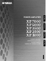
English
Français
Deutsch
POWER AMPLIFIER
Español
OWNER’S MANUAL
BEDIENUNGSANLEITUNG
MODE D’EMPLOI
MANUAL DE INSTRUCCIONES
EN
DE
FR
ES
FCC INFORMATION (U.S.A.)
1. IMPORTANT NOTICE: DO NOT MODIFY THIS UNIT!
This product, when installed as indicated in the instructions contained in this manual, meets FCC requirements. Modifications not
expressly approved by Yamaha may void your authority, granted by the FCC, to use the product.
2. IMPORTANT: When connecting this product to accessories and/or another product use only high quality shielded cables. Cable/s
supplied with this product MUST be used. Follow all installation instructions. Failure to follow instructions could void your FCC authorization to use this product in the USA.
* This applies only to products (XP7000, XP5000) distributed by YAMAHA CORPORATION OF AMERICA.
(oscillator)
Explanation of Graphical Symbols
The lightning flash with arrowhead symbol
within an equilateral triangle is intended to alert
the user to the presence of uninsulated
“dangerous voltage” within the product’s
enclosure that may be of sufficient magnitude to
constitute a risk of electric shock to persons.
CAUTION
RISK OF ELECTRIC SHOCK
DO NOT OPEN
The exclamation point within an equilateral
triangle is intended to alert the user to the
presence of important operating and
maintenance (servicing) instructions in the
literature accompanying the product.
CAUTION: TO REDUCE THE RISK OF
ELECTRIC SHOCK, DO NOT REMOVE
COVER (OR BACK). NO USER-SERVICEABLE
PARTS INSIDE. REFER SERVICING TO
QUALIFIED SERVICE PERSONNEL.
The above warning is located on the top of the unit.
IMPORTANT SAFETY INSTRUCTIONS
1
2
3
4
5
6
7
8
9
10
Read these instructions.
Keep these instructions.
Heed all warnings.
Follow all instructions.
Do not use this apparatus near water.
Clean only with dry cloth.
Do not block any ventilation openings. Install in
accordance with the manufacturer’s instructions.
Do not install near any heat sources such as radiators,
heat registers, stoves, or other apparatus (including
amplifiers) that produce heat.
Do not defeat the safety purpose of the polarized or
grounding-type plug. A polarized plug has two blades
with one wider than the other. A grounding type plug
has two blades and a third grounding prong. The wide
blade or the third prong are provided for your safety. If
the provided plug does not fit into your outlet, consult
an electrician for replacement of the obsolete outlet.
Protect the power cord from being walked on or pinched
particularly at plugs, convenience receptacles, and the
point where they exit from the apparatus.
11
12
13
14
Only use attachments/accessories specified by the
manufacturer.
Use only with the cart, stand,
tripod, bracket, or table specified
by the manufacturer, or sold with
the apparatus. When a cart is
used, use caution when moving
the cart/apparatus combination
to avoid injury from tip-over.
Unplug this apparatus during
lightning storms or when unused for long periods of
time.
Refer all servicing to qualified service personnel.
Servicing is required when the apparatus has been
damaged in any way, such as power-supply cord or plug
is damaged, liquid has been spilled or objects have
fallen into the apparatus, the apparatus has been
exposed to rain or moisture, does not operate normally,
or has been dropped.
WARNING
TO REDUCE THE RISK OF FIRE OR ELECTRIC SHOCK, DO NOT EXPOSE THIS APPARATUS TO RAIN OR MOISTURE.
(98-6500)
2
XP7000/XP5000/XP3500/XP2500/XP1000 Owner’s Manual
PRECAUTIONS
PLEASE READ CAREFULLY BEFORE PROCEEDING
* Please keep this manual in a safe place for future reference.
WARNING
Always follow the basic precautions listed below to avoid the possibility of serious injury or even death from electrical
shock, short-circuiting, damages, fire or other hazards. These precautions include, but are not limited to, the following:
Power supply/Power cord
Water warning
• Only use the voltage specified as correct for the device. The required voltage is
printed on the name plate of the device.
• Do not expose the device to rain, use it near water or in damp or wet conditions,
or place containers on it containing liquids which might spill into any openings.
• Use only the included power cord.
• Never insert or remove an electric plug with wet hands.
• Do not place the power cord near heat sources such as heaters or radiators, and
do not excessively bend or otherwise damage the cord, place heavy objects on
it, or place it in a position where anyone could walk on, trip over, or roll anything
over it.
• Be sure to connect to an appropriate outlet with a protective grounding
connection. Improper grounding can result in electrical shock.
Do not open
• Do not open the device or attempt to disassemble the internal parts or modify
them in any way. The device contains no user-serviceable parts. If it should
appear to be malfunctioning, discontinue use immediately and have it inspected
by qualified Yamaha service personnel.
If you notice any abnormality
• If the power cord or plug becomes frayed or damaged, or if there is a sudden
loss of sound during use of the device, or if any unusual smells or smoke
should appear to be caused by it, immediately turn off the power switch,
disconnect the electric plug from the outlet, and have the device inspected by
qualified Yamaha service personnel.
• If this device should be dropped or damaged, immediately turn off the power
switch, disconnect the electric plug from the outlet, and have the device
inspected by qualified Yamaha service personnel.
CAUTION
Always follow the basic precautions listed below to avoid the possibility of physical injury to you or others, or damage
to the device or other property. These precautions include, but are not limited to, the following:
Power supply/Power cord
• Do not block the vents. This device has ventilation holes at the front and rear to
prevent the internal temperature from becoming too high. In particular, do not
place the device on its side or upside down. Inadequate ventilation can result in
overheating, possibly causing damage to the device(s), or even fire.
• Remove the electric plug from the outlet when the device is not to be used for
extended periods of time, or during electrical storms.
• When removing the electric plug from the device or an outlet, always hold the
plug itself and not the cord. Pulling by the cord can damage it.
• Do not use the device in the vicinity of a TV, radio, stereo equipment, mobile
phone, or other electric devices. Doing so may result in noise, both in the device
itself and in the TV or radio next to it.
Location
• Before moving the device, remove all connected cables.
• Do not place the device in a location where it may come into contact with
corrosive gases or salt air. Doing so may result in malfunction.
• When setting up the product, make sure that the AC outlet you are using is
easily accessible. If some trouble or malfunction occurs, immediately turn off
the power switch and disconnect the plug from the outlet. Even when the power
switch is turned off, electricity is still flowing to the product at the minimum
level. When you are not using the product for a long time, make sure to unplug
the power cord from the wall AC outlet.
• Before connecting the device to other devices, turn off the power for all devices.
Before turning the power on or off for all devices, set all volume levels to
minimum.
• Do not use the device in a confined, poorly-ventilated location. If this device is
to be used in a small space other than an EIA-standard rack, make sure that
there is adequate space between the device and surrounding walls or other
devices: at least 5cm at the sides, 10cm behind and 10cm above. Inadequate
ventilation can result in overheating, possibly causing damage to the device(s),
or even fire.
• Do not expose the device to excessive dust or vibrations, or extreme cold or heat
(such as in direct sunlight, near a heater, or in a car during the day) to prevent
the possibility of panel disfiguration or damage to the internal components.
• Do not place the device in an unstable position where it might accidentally fall
over.
(5)-4
Connections
• Use only speaker cables for connecting speakers to the speaker jacks. Use of
other types of cables may result in fire.
• Be sure to connect to a properly grounded power source. A ground screw is
provided on the rear panel of this device for maximum safety and shock
prevention. If the mains outlet is not grounded, be sure to connect the ground
screw to a confirmed ground point before plugging the device into the mains.
Improper grounding can result in electrical shock.
Maintenance
• Remove the power plug from the AC outlet when cleaning the device.
1/2
XP7000/XP5000/XP3500/XP2500/XP1000 Owner’s Manual
3
Handling caution
• When turning on the AC power in your audio system, always turn on the device
LAST, to avoid speaker damage. When turning the power off, the device should
be turned off FIRST for the same reason.
• Do not insert your fingers or hands in any gaps or openings on the device
(vents, etc.).
• Do not use the device for a long period of time at a high or uncomfortable
volume level, since this can cause permanent hearing loss. If you experience any
hearing loss or ringing in the ears, consult a physician.
• Do not rest your weight on the device or place heavy objects on it, and avoid use
excessive force on the buttons, switches or connectors.
• Do not use this device for any purpose other than driving loudspeakers.
• Avoid inserting or dropping foreign objects (paper, plastic, metal, etc.) into any
gaps or openings on the device (vents, etc.) If this happens, turn off the power
immediately and unplug the power cord from the AC outlet. Then have the
device inspected by qualified Yamaha service personnel.
Yamaha cannot be held responsible for damage caused by improper use or modifications to the device, or data that is lost or destroyed.
Always turn the power off when the device is not in use.
Even when the power switch is in the “STANDBY”, electricity is still flowing to the device at the minimum level. When you are not using the device for a long time, make sure
you unplug the power cord from the wall AC outlet.
The performance of components with moving contacts, such as switches, volume controls, and connectors, deteriorates over time. Consult qualifi ed Yamaha service personnel
about replacing defective components.
Illustrations in this manual are for explanatory purposes only, and may not match the actual appearance of the product during operation.
Company names and product names used in this Owner’s Manual are trademarks or registered trademarks of their respective owners.
IMPORTANT NOTICE FOR THE UNITED KINGDOM
Connecting the Plug and Cord
WARNING: THIS APPARATUS MUST BE EARTHED
IMPORTANT. The wires in this mains lead are coloured in accordance with the following code:
GREEN-AND-YELLOW : EARTH
BLUE
: NEUTRAL
BROWN
: LIVE
As the colours of the wires in the mains lead of this apparatus may not correspond with the
coloured markings identifying the terminals in your plug proceed as follows:
The wire which is coloured GREEN-and-YELLOW must be connected to the terminal in the plug
which is marked by the letter E or by the safety earth symbol
or colored GREEN or GREENand-YELLOW.
The wire which is coloured BLUE must be connected to the terminal which is marked with the
letter N or coloured BLACK.
The wire which is coloured BROWN must be connected to the terminal which is marked with the
letter L or coloured RED.
• This applies only to products distributed by Yamaha-Kemble Music (U.K.) Ltd.
(3 wires)
This mark indicates a dangerous electrically live terminal. When connecting an external wire to this terminal, it is necessary
either to have “a person who have received appropriate guidance on handling” make the connection or to use leads or a cord
that have been manufactured in such a way that the connection can be made simply and without problem.
(5)-4
4
XP7000/XP5000/XP3500/XP2500/XP1000 Owner’s Manual
2/2
Introduction
Thank you for purchasing a Yamaha XP7000, XP5000, XP3500, XP2500, XP1000 Series Power Amplifier.
The XP Series of power amplifiers was developed from Yamaha’s wealth of experience in building PA
equipment and its tradition of careful attention to every detail of circuit design. These power amplifiers
feature high power — thanks to EEEngine (Energy Efficient Engine) technology — and superb quality
together with superior reliability and stability, guaranteeing the highest possible audio performance.
Main features include
• Three modes are provided to support a broad range of applications: STEREO mode which can be driven by two
independent sources, PARALLEL mode in which a monaural source drives both channels, and BRIDGE mode in
which the two internal amps function as a single high-power mono amp.
• Balanced XLR connector and Euroblock connector inputs, and Speakon connector and five-way binding post
outputs are provided.
• A high pass filter switch that enables selection of the cutoff frequency (20Hz or 55Hz).
• Signal indicator, clip indicator and sophisticated dB step Volume control are provided for each channel.
• A PROTECTION indicator that shows the state of various protection systems (power on/off detection, output
protection, DC detection), a TEMP indicator that indicates heat sink overheating, and a POWER/STANDBY
indicator that indicates the power status.
• Variable-speed low-noise fans ensure high reliability.
• The XP7000 enables parallel connection of multiple high-impedance speakers that support 70V line output.
• The XP3500 enables parallel connection of multiple high-impedance speakers that support 100 V line output.
• A MONITOR/REMOTE terminal that allows monitoring or control over the amplifier via a network.
This Owner’s Manual applies to the XP7000, XP5000, XP3500, XP2500, XP1000 power amplifier. In
order to take full advantage of your power amplifier and enjoy long and trouble-free operation, please
read this Owner’s Manual carefully before using your Power Amplifier.
Contents
Controls and Functions............................6
Front Panel ......................................................... 6
Rear Panel ......................................................... 7
Speaker Connections .............................. 8
Stereo Mode ....................................................... 8
Parallel Mode ..................................................... 8
Bridged Mode
(use as high-power mono amplifier) ................... 9
High-impedance speaker connections .. 10
Connection ............................................. 11
Using a Euroblock connector ........................... 11
Speaker Connection ......................................... 11
Troubleshooting ..................................... 12
Specifications ......................................... 13
General Specifications ..................................... 13
MONITOR/REMOTE PIN layout ...................... 15
Dimensions ...................................................... 15
Block Diagram .................................................. 16
Current Draw .................................................... 18
XP7000/XP5000/XP3500/XP2500/XP1000 Owner’s Manual
5
Controls and Functions
■ Front Panel
2
7
1
4
3
5 6
7
* The illustration shows model XP7000.
1 POWER switch and indicator
Press this to turn the power on or off. The POWER/
STANDBY indicator lights up in green when the power
is ON. If the amplifier has been set to STANDBY mode,
the indicator is lit in orange.
2 TEMP indicator
Lights up red if the heat sink temperature exceeds 85°C
(185°F).
3 PROTECTION indicator
When the protection system is active, the PROTECT
indicator light up in red and the speakers are automatically disconnected from the amplifier’s outputs. The
protection system activates in the following situations:
When the amplifier is turned on
The protection system activates for approximately
three seconds when the amplifier is turned on. After
three seconds, the protection system deactivates automatically and the amplifier is ready for normal operation.
5 SIGNAL indicator
Lights up green when the corresponding channel’s output level exceeds 2 Vrms (equivalent to 1/2 W into an 8
Ω load, or 1 W into a 4 Ω load).
6 Volume control knobs
Each control knob adjusts the volume of the corresponding channel, in 31 steps from -∞ dB to 0 dB.
* If you wish to lock in the knob settings, you can
fasten the supplied security cover over the
knobs so that the settings will not be disturbed.
● How to install the security cover
(1) Use the supplied hex wrench to remove the four
attachment screws from the amplifier.
(2) Adjust the security cover to the position of screw
holes. Fasten it into place using the same screws.
If a DC voltage is detected at the amplifier’s
outputs
XP7000/5000: Power shut down and the indicator is
not lit.
XP3500/2500/1000: The protection system is active.
Once the DC voltage problem is corrected, the protection system deactivates automatically and the amplifier is ready for normal operation.
If the amplifier overheats
When overheating occurs, the PROTECT/MUTE
indicator lights. You should immediately turn off the
amplifier and allow it time to cool down. See the Precautions section of this Owner’s Manual for ways to
prevent the amplifier from overheating.
4 CLIP indicator
Lights up red when the output signal distortion on the
corresponding channel rises above 1% — indicating
that “clipping” has occurred bacause the signal level is
too high.
7 Air intakes
The amplifier uses forced-air cooling. The cooling fans
draw air in from the front and exhaust it through the
rear. Please be sure that you do not block the air intakes
or exhaust vents.
* The fans do not come on at initial power-on, but
will switch on automatically when the temperature
of the heat sink rises above 50°C (122°F). The fan
speed will then vary automatically as the temperature changes.
Front
Air
intake
6
XP7000/XP5000/XP3500/XP2500/XP1000 Owner’s Manual
Rear
Air
exhaust
■ Rear Panel
4
3
1
5
2
1 XLR inputs connectors
7
8
5 MODE switch
These balanced XLR-3-31 type connectors are used to
connect input signals.
The pins are wired as shown below (IEC 60268).
Hot
7
6
Ground
Cold
* In bridged mode, only the first channel in the pair
is active; i.e., channel A of pair A/B. Make sure not
to input an audio signal to an inactive input terminal.
2 Euroblock connectors
These balanced Euroblock connectors are used to connect input signals.
3 HPF switches
These switches are used to turn on and off the HPF
(High Pass Filter) for each channel. When this is set to
20Hz or 55Hz, frequencies below the respective settings
are filtered using a 12 dB/octave high pass filter.
4 GAIN switch
This switch is used when changing the Gain of the A
and B channels simultaneously.
• +4dBu: The maximum output power can be
obtained when +4dBu is input.
• 26dB: Setting of 26dB
• 32dB: Setting of 32dB
• STEREO mode
In STEREO mode, channels A and B are completely
independent.
• PARALLEL mode
In PARALLEL mode, the channel A input signal is
sent both to the channel A power amp and the channel
B power amp. In this case, loads are automatically
connected between the A and B input terminals.
• BRIDGED mode
In BRIDGED mode, channels A and B operate simultaneously, functioning as a single mono amplifier.
Note: When in PARALLEL and BRIDGED modes,
input terminals A and B are shorted automatically. Make sure not to input an audio
signal to an inactive input terminal.
6 MONITOR/REMOTE terminals
This terminal is used to connect the external device for
monitoring or remote control. Refer to “MONITOR/
REMOTE PIN layout” on page 15.
7 SPEAKERS terminals
1: These 5-way binding posts are used to connect
speakers.
2: These are Speakon type output jacks. Speakon type
cable plugs can be connected here.
8 GND terminal
If you are having a problem with hum or noise, use this
terminal to connect to ground (earth) or to connect to
the chassis of a mixer, preamp, or other device in your
system.
XP7000/XP5000/XP3500/XP2500/XP1000 Owner’s Manual
7
Speaker Connections
Speakers can be connected to the amplifier in three ways, as shown below. Note that speaker impedance will vary according
to the connection method and the number of speakers. Please be sure that your speaker's impedance is not less than the relevant minimum value indicated below.
■ Stereo Mode
Set the Mode switch to STEREO to use the unit as a stereo amplifier. The volume controls on the front panel (A and B) let
you control the volume of each channel independently.
● 5-way binding post
● Speakon connector
–
+
+
4Ω*
–
4Ω*
4Ω*
* Minimum speaker
impedance
4Ω*
* Minimum speaker
impedance
■ Parallel Mode
Set the Mode switch to PARALLEL to use the unit as a two-channnel mono amplifier. The volume controls on the front
panel (A and B) let you control the volume of each channel independently.
Note: In this case, the loads for A and B are connected directly in the amplifier. Make sure not to input any signal
to the B terminal.
● 5-way binding post
● Speakon connector
–
+
4Ω*
+
–
4Ω*
* Minimum speaker
impedance
8
XP7000/XP5000/XP3500/XP2500/XP1000 Owner’s Manual
4Ω*
4Ω*
* Minimum speaker
impedance
■ Bridged Mode (use as high-power mono amplifier)
Set the Mode switch to BRIDGE to use the unit as a high-power mono amplifier. The volume control A on the front panel A
lets you control the volume.
Note: In this case, the loads for A and B are directly connected in the amplifier. Make sure not to input any signal
to the B terminal.
● 5-way binding post
● Speakon connector
–
+
Minimum speaker
impedance: 8Ω
Minimum speaker
impedance: 8Ω
XP7000/XP5000/XP3500/XP2500/XP1000 Owner’s Manual
9
High-impedance speaker connections
(XP7000/3500 only)
The XP7000 enables you to connect in stereo or parallel fashion multiple high-impedance speakers that support 70V line
output.
The number of speakers that can be connected varies depending on the speaker’s rated input. You can connect speakers with
a total rated input per channel of up to 625 W.
For example, if you are using speakers with a rated input of 10 W and 15 W, you can connect up to 31 speakers at 10 W (for
310W), and 21 speakers at 15 W (for 315 W). The total is 625 W per channel.
Be sure to use speakers that support the XP7000’s line-out voltage of 70 V.
or
1
21
1
31
15W
15W
10W
10W
15W x 21 speakers (315W)
1
31
1
10W
10W x 31 speakers (310W)
10W
10W x 31 speakers (310W)
21
15W
15W
15W x 21 speakers (315W)
Total rated input of speakers: 625 W (maximum)
Total rated input of speakers: 625 W (maximum)
The XP3500 enables you to connect in bridge fashion multiple high-impedance speakers that support 100V line output.
You can connect speakers with a total rated input of up to 625 W.
Be sure to use speakers that support the XP3500’s line-out voltage of 100 V.
1
31
10W
1
10W
10W x 31 speakers (310W)
21
15W
15W
15W x 21 speakers (315W)
Total rated input of speakers: 625 W (maximum)
10
XP7000/XP5000/XP3500/XP2500/XP1000 Owner’s Manual
Connection
■ Using a Euroblock connector
Use a screwdriver
to fix the wires.
If cables will be frequently connected and disconnected,
as in the case of a portable installation, we recommend
that you use ferrules with insulation sleeves. Use a ferrule whose conductor portion has an external diameter of
1.6mm or less, and a length of approximately 7 mm
(such as the AI0,5-6WH made by the Phoenix Contact
corporation).
1 If the wire insertion ports are closed, turn the screws on
top of the connector counterclockwise to open the ports.
2 Insert the wires into the appropriate ports, following the
indication of the pole on the input terminal, turn the
screws on top of the connector clockwise to fix the
wires.
3 Attach the Euroblock connector to the input terminal on
the unit.
+
–
G
■ Speaker Connection
● 5-way binding post
1 Turn off the POWER switch.
2 Remove the cover attachment screws and remove the
protective cover from the speaker terminals.
Be sure that the bare wire ends do not jut out from the
terminals and touch the chassis.
Chassis
Bare wire
Screw
3 Remove about 15 mm of insulation from the end of each
speaker cable.
Pass the bare wire through the holes in the appropriate
speaker terminals. Tighten the terminals to securely
clamp the wires. Refer to page 8 for speaker polarities.
15mm*
4 Reattach the protective cover over the speaker terminals.
Speaker
cable
* Actual size
● Speakon connector
1 Turn off the POWER switch.
2 Insert the Neutrik NL4FC plugs into the Speakon connector on the rear of the amplifier, and turn clockwise to
lock.
Neutrik NL4FC plugs
CHANNEL Å
STEREO or PARALLEL
1+
1–
2+
2–
A+
A–
B+
B–
BRIDGE
1+
1–
2+
2–
+
–
CHANNEL ı
1+
1–
B+
B–
XP7000/XP5000/XP3500/XP2500/XP1000 Owner’s Manual
11
Troubleshooting
The following table lists the main causes of abnormal operation and the corrective measures required as well as the protective circuit operation in each case.
Indicator(s)
Possible Cause
Remedy
There is a short at a speaker terminal, amplifier terminal, or wire.
Locate and correct the cause of
the short.
The amplifier load is excessive.
Use a speaker system with an
impedance of at least 4 Ω (STEREO/PARALLEL mode) or 8 Ω
(BRIDGE mode).
TEMP indicator lights.
The heat sink temperature has
exceeded 85°C (185°F).
Check the ventilation slots, and
provide better airflow around the
amplifier.
The TEMP indicator
lights up to indicate temperature warning.
PROTECTION indicator lights.
The heat sink temperature has
exceeded 90°C (194°F).
Check the amplifier ventilation
conditions and take appropriate
measures to improve the airflow
around the amplifier.
The thermal protection
circuit operates to protect
the power transistors.
Remedy
Protection Circuit
CLIP indicator lights.
Protection Circuit
The PC limiter circuit
operates to protect the
power transistors.
● XP3500, XP2500
Indicator(s)
PROTECTION indicator lights.
Possible Cause
A DC voltage of +2 V/-2 V or
greater was generated in the
power amplifier’s output circuit.
Consult your dealer or the nearest Yamaha service center.
The relay operates to
protect the speaker system.
● XP7000, XP5000
Indicator(s)
Power has been shut
down. (All indicators
are off.)
12
Possible Cause
A DC voltage of +2 V/-2 V or
greater was generated in the
power amplifier’s output circuit.
XP7000/XP5000/XP3500/XP2500/XP1000 Owner’s Manual
Remedy
Protection Circuit
Consult your dealer or the nearest Yamaha service center.
The protection circuitry
shut off the power to protect the speaker system.
Specifications
■ General Specifications
XP7000
Output Power
1 kHz
THD+N= 1 %
20 –20 kHz
THD+N= 0.1 %
1 kHz
20mS nonclip
SN Ratio
Power
Consumption
20Hz-20kHz
Standby / Idle
1/8 (4 Ω/Pink noise)
8 Ω/STEREO
4 Ω/STEREO
8 Ω/BRIDGED
8 Ω/STEREO
4 Ω/STEREO
70 V/STEREO RL=8 Ω
8 Ω/BRIDGED
2 Ω/STEREO
4 Ω/BRIDGED
(DIN AUDIO)
MIN
1 kHz
THD+N= 1 %
20 –20 kHz
THD+N= 0.1 %
1 kHz
20mS nonclip
SN Ratio
Power
Consumption
20Hz-20kHz
Standby /idle
1/8 (4 Ω/Pink noise)
8 Ω/STEREO
4 Ω/STEREO
8 Ω/BRIDGED
8 Ω/STEREO
4 Ω/STEREO
8 Ω/BRIDGED
2 Ω/STEREO
4 Ω/BRIDGED
(DIN AUDIO)
MIN
1 kHz
THD+N= 1 %
20 –20 kHz
THD+N= 0.1 %
1 kHz
20mS nonclip
SN Ratio
Power
Consumption
20Hz-20kHz
Standby / idle
1/8 (4 Ω/Pink noise)
8 Ω/STEREO
4 Ω/STEREO
8 Ω/BRIDGED
8 Ω/STEREO
4 Ω/STEREO
8 Ω/BRIDGED
100 V/BRIDGED RL=16 Ω
2 Ω/STEREO
4 Ω/BRIDGED
(DIN AUDIO)
MIN
1 kHz
THD+N= 1 %
20 –20 kHz
THD+N= 0.1 %
1 kHz
20mS nonclip
SN Ratio
Power
Consumption
20Hz-20kHz
Standby / idle
1/8 (4 Ω/Pink noise)
8 Ω/STEREO
4 Ω/STEREO
8 Ω/BRIDGED
8 Ω/STEREO
4 Ω/STEREO
8 Ω/BRIDGED
2 Ω/STEREO
4 Ω/BRIDGED
(DIN AUDIO)
MIN
1 kHz
THD+N= 1 %
20 –20 kHz
THD+N= 0.1 %
1 kHz
20mS nonclip
SN Ratio
Power
Consumption
20 Hz-20 kHz
Standby / idle
1/8 (4 Ω/Pink noise)
8 Ω/STEREO
4 Ω/STEREO
8 Ω/BRIDGED
8 Ω/STEREO
4 Ω/STEREO
8 Ω/BRIDGED
2 Ω/STEREO
4 Ω/BRIDGED
(DIN AUDIO)
120 V
230 V
240 V
525 W+525 W
750 W+750 W
1500 W
500 W+500 W
700 W+700 W
1400 W
1300 W+1300 W
2600 W
525 W+525 W
750 W+750 W
1500 W
500 W+500 W
700 W+700 W
1400 W
1300 W+1300 W
2600 W
500 W
525 W+525 W
750 W+750 W
1500 W
500 W+500 W
700 W+700 W
1400 W
1300 W+1300 W
2600 W
103 dB
5 W / 35 W
500 W
120 V
230 V
240 V
390 W+390 W
590 W+590 W
1180 W
350 W+350 W
450 W+450 W
900 W
625 W
1000 W+1000 W
2000 W
390 W+390 W
590 W+590 W
1180 W
350 W+350 W
450 W+450 W
900 W
625 W
1000 W+1000 W
2000 W
450 W
390 W+390 W
590 W+590 W
1180 W
350 W+350 W
435 W+435 W
870 W
625 W
925 W+925 W
1850 W
102 dB
5 W / 30
450 W
120 V
230 V
240 V
275 W+275 W
390 W+390 W
780 W
250 W+250 W
300 W+300 W
600 W
650 W+650 W
1300 W
275 W+275 W
390 W+390 W
780 W
250 W+250 W
300 W+300 W
600 W
650 W+650 W
1300 W
320 W
275 W+275 W
390 W+390 W
780 W
250 W+250 W
295 W+295 W
590 W
650 W+650 W
1300 W
100 dB
5 W / 25 W
320 W
120 V
230 V
240 V
135 W+135 W
165 W+165 W
330 W
110 W+110 W
125 W+125 W
250 W
250 W+250 W
500 W
125 W+125 W
155 W+155 W
310 W
100 W+100 W
115 W+115 W
230 W
250 W+250 W
500 W
96 dB
5 W / 20 W
170 W
120 W+120 W
155 W+155 W
310 W
100 W+100 W
110 W+110 W
220 W
250 W+250 W
500 W
MIN
XP1000
Output Power
650 W
MIN
XP2500
Output Power
240 V
750 W + 750 W
1100 W + 1100 W
2200 W
700 W + 700 W
950 W + 950 W
625 W + 625 W
1900 W
1600 W + 1600 W
3200 W
MIN
XP3500
Output Power
230 V
750 W + 750 W
1100 W + 1100 W
2200 W
690 W + 690 W
950 W + 950 W
625 W + 625 W
1900 W
1600 W + 1600 W
3200 W
104 dB
5 W / 35 W
650 W
MIN
XP5000
Output Power
120 V
750 W + 750 W
1100 W + 1100 W
2200 W
700 W + 700 W
950 W + 950 W
625 W + 625 W
1900 W
1600 W + 1600 W
3200 W
MIN
MIN
170 W
650 W
500 W
450 W
320 W
170 W
XP7000/XP5000/XP3500/XP2500/XP1000 Owner’s Manual
13
All Models
Power Bandwidth
THD+N
Intermoduration Distortion
Frequency Response
Half Power, THD+N= 0.5 %
20 Hz–20 kHz, Half Power
60 Hz:7 kHz, 4:1, Half Power
RL=8 Ω, Po=1 W, HPF=OFF
20 Hz-50 kHz
Channel Separation
Half Power, RL=8 Ω, 1 kHz,
Att. max, input 600 Ω shunt
20 Hz–20 kHz, Att. min,
(DIN AUDIO)
RL=8 Ω, 1 kHz
Att. max
Residual Noise
Damping Factor
Voltage Gain
MIN
MAX
MAX
MAX
TYP
MIN
10 Hz-40 kHz
0.1 %
0.1 %
0 dB
0 dB
-1 dB
MIN
70 dB
MAX
-70 dBu
MIN
350 (XP7000, XP5000), 200 (XP3500, XP2500, XP1000)
XP7000
XP5000
XP3500
XP2500
XP1000
Selectable from 32 dB or 26 dB (or +4 dBu input sensitivity) by select switch
TYP
+4 dBu
position
Input Sensitivity (dBu)
Att. max
(Rated Power 8 Ω,
20Hz–20kHz, THD+N = 0.1%)
+4 dBu
position
26 dB
position
32 dB
position
Maximum Input Voltage
Input Impedance
Controls
MIN
TYP
Front Panel
Rear Panel
Connectors
Indicators
Input
Output
MONITOR/REMOTE
POWER/STANDBY
SIGNAL
CLIP/LIMIT
PROTECTION/TEMP
Load Protection
Amplifier Protection
Power Supply Protection
Cooling
Power Requirements
Dimensions (W x H x D)
Weight
Included Accessories
* These specifications apply to rated power supplies of 120V, 230V and 240V.
0 dBu=0.775 Vrms, Half Power=1/2 Output Power (3 dB below rated power)
Specifications and descriptions in this owner’s manual are for information purposes only.
Yamaha Corp. reserves the right to change or modify products or specifications at any time without prior notice. Since specifications, equipment or
options may not be the same in every locale, please check with your Yamaha
dealer.
14
XP7000/XP5000/XP3500/XP2500/XP1000 Owner’s Manual
35.7 dB
34.2 dB
32.7 dB
31.2 dB
27.2 dB
XP7000
XP5000
XP3500
XP2500
XP1000
+4 dBu
+4 dBu
+4 dBu
+4 dBu
+4 dBu
+12.2 dBu
+10.7 dBu
+9.2 dBu
+5.2 dBu
+13.7 dBu
(120V / 240V)
+13.6 dBu
(230V)
+7.7 dBu
(120V / 240V)
+6.2 dBu
+4.7 dBu
+3.2 dBu
-0.8 dBu
+7.6 dBu
(230V)
+22 dBu
20 kΩ (balanced), 10 kΩ (unbalanced)
POWER switch (push on/push off)
attenuator (31 position) x 2
MODE switch (STEREO/BRIDGED/PARALLEL) x 1
HPF switch (20 Hz/55 Hz/OFF 12 dB/oct) x 2
GAIN SELECT switch (32 dB/26 dB/+4 dBu) x 1
XLR-3-31 type/ch, Euroblock connector (balanced) /ch
SPEAKON/ch, 5 way binding post x 1
Dsub 15 P x 1
x 1 (Green/Orange)
x 2 (Green)
x 2 (Red)
x 1 (Red)
x 1 (Red) heatsink temp. ≥ 85 °C
POWER switch on/off mute
DC-fault:
power supply shutdown/operation not restored automatically. (XP7000, XP5000)
output relay off/restored automatically. (XP3500, XP2500, XP1000)
Clip limiting : THD ≥ 0.5 %
Thermal:
Cuts the output (heatsink temp. ≥ 90 °C) ; operation not restored automatically.
VI limiter (RL ≤ 1 Ω): Limit the output.
Thermal:
Power supply shutdown (heatsink temp. ≥ 100 °C) ; operation not restored automatically. (XP7000, XP5000).
power supply shutdown (transfomer temp. ≥ 130 °C)
; restored automatically. (XP3500, XP2500, XP1000)
Variable-speed fan: x 1(XP3500, XP2500, XP1000), x 2 (XP7000, XP5000)
Fan stop at heatsink temp. < 55 °C
120V, 220V–240V; 50Hz/60Hz
480 x 88 x 456 mm (18-7/8" x 3-7/16" x 17-15/16")
XP7000
XP5000
XP3500
XP2500
XP1000
14.0 kg
14.0 kg
15.0 kg
14.0 kg
12 kg
(30.9 lbs)
(30.9 lbs)
(33.1 lbs)
(30.9 lbs)
(26.5 lbs)
Security cover (with a hex wrench), Owner’s Manual
European models
Purchaser/User Information specified in EN55103-1 and EN55103-2.
Inrush Current: XP7000/5000 25A , XP3500 22A, XP2500 20A, XP1000 14A
Conforms to Environments: E1, E2, E3 and E4
■ MONITOR/REMOTE PIN layout
Pin No.
1
2
3
Signal
GND
REMOTE CONTROL
MONITOR
4
5
6
7
REMOTE CONTROL
8
9
10
11
12
13
14
15
MONITOR
Description
STANDBY
MODEL ID
STANDBY Control: Supply 5 VDC, 5 mADC
XP7000: 1.0 kΩ, XP5000: 1.2 kΩ, XP3500: 1.5 kΩ,
XP2500: 1.8 kΩ, XP1000: 2.2 kΩ (Impedance to GND)
NC
NC
MUTE CH B
MUTE CH A
MUTE On Control: Connect the pin to GND (max. 1mA flows)
MUTE Off Control: Open the pin (+5V applied)
NC
NC
PROTECTION/MUTE STATUS CH B
PROTECTION/MUTE STATUS CH A
NC
NC
OUTPUT LEVEL CH B
OUTPUT LEVEL CH A
Protection/Mute On: +5 VDC, Zo=270 Ω
Protection/Mute Off: 0 VDC, Zo=High
XP7000, XP5000, XP3500, XP2500, XP1000
+4dBu (-27.2 dB of Speaker Output Level) at 100 W/8Ω, RL=7.5 kΩ, Zo=300 Ω
■ Dimensions
46
5.5
456
374.5
30
Unit: mm
362
30
480
88
30
XP7000/XP5000/XP3500/XP2500/XP1000 Owner’s Manual
15
16
XP7000/XP5000/XP3500/XP2500/XP1000 Owner’s Manual
–
+
G
–
+
G
3
2
LINE
FILTER
XLR
1
Euroblock
FG
CH B
[+22dBu MAX]
INPUT
CH A
3
2
XLR
1
+24
RELAY DRIVE
CIRCUIT
RELAY
POWER SW
GR/OR (GR+RE)
POWER/STANDBY
PARALLEL
BRIDGE
STEREO
PARALLEL
BRIDGE
STEREO
CH B ATT
CH A ATT
U, A
destination
J, H
destination
Thermal
cutoff
SUB TRANS
PO
SBY LED DRIVE
CIRCUIT
HA
HA
MODE
BA
BA
HPF
55Hz
OFF
55Hz
TEMPERATURE
SENSOR
OVERCURRENT
DETECT CIRCUIT
DRIVER
LATCH
CIRCUIT
LIMITER
PA
PA
–15V
+15V
+5V
GR
GR
FAN
(R)
FAN
(L)
+24
–B
+B
–24
–15
+15
+5
B DC
PR
RE
SHUTDOWN
BPS
B MUTE
APS
A MUTE
LED DRIVE
CIRCUIT
TM
RE
TEMP PROTECTION
PROTECTION
CIRCUIT
B MUTE
TEMP
A DC
ASIG BSIG
A MUTE
ACL BCL
POWER ON
DETECT CIRCUIT
LIMITER
TEMPERATURE
SENSOR
+60˚C +90˚C
TEMPERATURE
SENSOR
+60˚C +90˚C
FAN CONTROL
CIRCUIT
MAIN TRANS
PARALLEL
BRIDGE
STEREO
INV
SHUTDOWN
CIRCUIT
+100˚C
55Hz
20Hz
SWITCHING
HPF
55Hz
HPF
20Hz
HPF 12dB/oct
+15V
+4dBu
+26dB
+32dB
GAIN
+4dBu
+26dB
+32dB
OFF
HPF 20Hz
20Hz
RE
LED DRIVE CIRCUIT
RE
SIGNAL
CH A CH B
CLIP/LIMIT
CH A CH B
1+
2+
2–
2–
–
–
+
+
CH B-1
(A+B BRIDGE)
CH A-1
OUTPUT
(SPEAKERS)
CH B-2
CH A-2
(A+B BRIDGE)
B OUTPUT LEVEL
A OUTPUT LEVEL
MUTE
PROTECT STATUS
STANDBY
Model ID
DATA PORT
(MONITOR/REMOTE)
5way
2+
SPEAKON
1–
1–
SPEAKON
1+
■ Block Diagram
● XP7000/XP5000
–
+
G
–
+
G
3
2
XLR
1
FG
Except J destination
PARALLEL
BRIDGE
STEREO
PARALLEL
BRIDGE
STEREO
POWER/STANDBY
POWER SW
GR/OR (GR+RE)
J destination only
CH B
Euroblock
[+22dBu MAX]
INPUT
CH A
3
2
XLR
1
RELAY 2
Thermal
cutoff
BA
BA
RELAY & LED
DRIVE CIRCUIT
MODE
CH B ATT
CH A ATT
RELAY 1
SUB TRANS
HA
HA
PO
SBY
HPF
55Hz
OFF
55Hz
55Hz
Thermal Thermal
cutoff
protector
MAIN TRANS
HPF
55Hz
HPF 20Hz
20Hz
HPF 12dB/oct
130˚C
+4dBu
+26dB
+32dB
GAIN
+4dBu
+26dB
+32dB
OFF
HPF 20Hz
20Hz
PARALLEL
BRIDGE
STEREO
INV
–15V
+15V
+90˚C
PA
–B
+B
–24
–15
+15
FAN
PA
B DC
A DC
TEMP
SP RELAY
B RY
PROTECTION
CIRCUIT
A RY
PR
RE
BPS
B MUTE
APS
A MUTE
LED DRIVE
CIRCUIT
TM
RE
TEMP PROTECTION
SP RELAY
ASIG BSIG
FAN CONTROL
CIRCUIT
+60˚C
TEMPERATURE
SENSOR
+24
LIMITER
LIMITER
ACL BCL
LED DRIVE CIRCUIT
GR
GR
RE
RE
SIGNAL
CH A CH B
CLIP/LIMIT
CH A CH B
1+
2–
–
CH A-1
+ CH B-1
– (A+B BRIDGE)
+
OUTPUT
(SPEAKERS)
CH B-2
B OUTPUT LEVEL
A OUTPUT LEVEL
MUTE
PROTECT STATUS
STANDBY
Model ID
DATA PORT
(MONITOR/REMOTE)
5way
2+
SPEAKON
1–
2+
SPEAKON
1+
CH A-2
1–
2– (A+B BRIDGE)
● XP3500/XP2500/XP1000
XP7000/XP5000/XP3500/XP2500/XP1000 Owner’s Manual
17
■ Current Draw
XP7000
Line Current (A)
100/120V
Power (W)
230/240V
In
Out
Thermal Dissipation
Dissipated
Btu/h
kcal/h
standby
0.08
0.04
5
0
5
17
4
idle
1.0
0.5
35
0
35
119
30
1/8 power
1/3 power
8Ω/ch
5.4
3.0
379
188
191
653
165
4Ω/ch
8.5
4.7
611
275
336
1150
289
8Ω/ch
12.8
7.0
918
500
418
1430
360
4Ω/ch
20.6
11.3
1481
733
748
2550
643
XP5000
Line Current (A)
100/120V
Power (W)
230/240V
In
Out
Thermal Dissipation
Dissipated
Btu/h
kcal/h
standby
0.08
0.04
5
0
5
17
4
idle
1.0
0.5
35
0
35
119
30
1/8 power
1/3 power
8Ω/ch
4.0
2.2
277
131
146
499
126
4Ω/ch
6.2
3.4
436
188
249
848
214
8Ω/ch
9.3
5.1
673
350
323
1100
278
4Ω/ch
14.7
8.1
1057
500
557
1900
479
XP3500
Line Current (A)
100/120V
Power (W)
230/240V
In
Out
Thermal Dissipation
Dissipated
Btu/h
kcal/h
standby
0.08
0.04
5
0
5
17
4
idle
1.0
0.5
30
0
30
102
26
1/8 power
1/3 power
8Ω/ch
3.2
1.7
227
98
130
443
112
4Ω/ch
5.0
2.8
378
148
231
787
198
8Ω/ch
7.3
4.0
551
260
291
993
250
4Ω/ch
12.2
6.7
917
393
524
1790
450
XP2500
Line Current (A)
100/120V
Power (W)
230/240V
In
Out
Thermal Dissipation
Dissipated
Btu/h
kcal/h
standby
0.08
0.04
5
0
5
17
4
idle
1.0
0.5
25
0
25
85
22
1/8 power
1/3 power
8Ω/ch
2.4
1.3
174
69
105
358
90
4Ω/ch
3.6
2.0
271
98
173
592
149
8Ω/ch
5.6
3.1
421
183
238
811
204
4Ω/ch
8.8
4.8
657
260
397
1350
341
XP1000
Line Current (A)
100/120V
Power (W)
230/240V
In
Out
Thermal Dissipation
Dissipated
kcal/h
standby
0.08
0.04
5
0
5
17
4
idle
1.0
0.5
20
0
20
68
17
8Ω/ch
1.1
0.6
76
28
48
165
42
4Ω/ch
1.2
0.7
91
30
61
208
52
8Ω/ch
2.4
1.3
184
73
110
376
95
4Ω/ch
2.9
1.6
220
80
140
479
121
1/8 power
1/3 power
1/8 power is typical of program material with occasional clipping. Refer to these figures for most applications.
1/3 power represents program material with extremely heavy clipping.
Test signal: Pink Noise, bandwidth limited from 22Hz to 22kHz
1W = 0.860kcal/h, 1BTU = 0.252kcal
Note that Line Voltage [V] x Line Current [A] = [VA], not equals to [W].
Inrush current
XP7000, XP5000:
XP3500:
XP2500:
XP1000:
18
Btu/h
11A (100V), 13A (120V), 25A (240V)
11A (100V), 13A (120V), 22A (240V)
10A (100V), 12A (120V), 20A (240V)
9A (100V), 11A (120V), 14A (240V)
XP7000/XP5000/XP3500/XP2500/XP1000 Owner’s Manual
Memo
XP7000/XP5000/XP3500/XP2500/XP1000 Owner’s Manual
19
Memo
20
XP7000/XP5000/XP3500/XP2500/XP1000 Owner’s Manual
Yamaha Pro Audio global web site:
http://www.yamahaproaudio.com/
Yamaha Manual Library:
http://www.yamaha.co.jp/manual/
C.S.G., Pro Audio Division
© 2005 Yamaha Corporation
305POAPx.x-01E0
Printed in Vietnam
WF37200