1
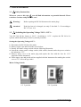
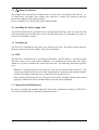
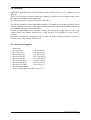
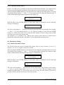
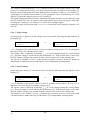
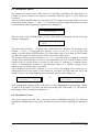
CONTENTS
1 General Information
3
1.1 Safety Instructions
3
1.2 Switching the Operating Voltage 230 V~/115 V~
3
1.3 Mains Connection
4
1.4 Installing the Power Supply Unit
4
1.5 Switching on
4
1.6 EMC
4
1.7 Inspection and Maintenance
4
1.8 Warranty
5
1.9 Accessories Supplied
5
2 Application
6
3 Set-up and Functional Description
6
3.1 Block Diagram
6
3.2 Description
7
4 Technical Data
8
4.1 General Data
8
4.2 Specifications
4.2.1 Characteristics of Sources A and B
4.2.2 Parallel Connection of Sources A and B
4.2.3 Source C (5 V/2 A)
8
8
9
9
4.3 Display
9
4.4 System Interfaces
4.4.1 Interface GPIB
4.4.2 Interface RS-232C
9
9
9
5 Control Elements
11
6 Parameter Settings
14
6.1 Starting
14
6.2 Selecting the Operating Mode
6.2.1 Independent Mode of Sources A und B
6.2.2 Tracking Mode of Source B to the Settings of Source A
6.2.3 Parallel Mode of Sources A and B
15
15
15
16
6.3 Function Mode of Sources
6.3.1 Constant Voltage Source
6.3.2 Constant Current Source
16
16
17
6.4 Parameter Setting
6.4.1 Mode of Parameter Input
17
17
1
Operating Instructions PN 300
1/99
6.4.2 Voltage Setting
6.4.3 Current Setting
18
18
6.5 Parameter Control
19
6.6 Parameter Pre-set
6.6.1 Storing the Pre-settings
6.6.2 Loading the Pre-settings
19
20
20
6.7 Error Messages
21
7 Remote Control by Program
22
7.1 Preparing the Power Supply Unit
7.1.1 Interface GPIB (IEEE-488.2)
7.1.2 Interface RS-232C
22
22
22
7.2 Transition: Remote Control ⇔ Local Control
23
7.3 Messages of the Power Supply Unit on Remote Control
7.3.1 Description of the Unit State
7.3.1.1 ESR - EVENT STATUS REGISTER
7.3.1.2 STB - STATUS BYTE REGISTER
7.3.2 Description of Results
7.3.3 Description of Errors
7.3.3.1 DER - DEVICE ERROR REGISTER
7.3.3.2 Error Messages
24
24
24
24
25
26
26
26
7.4 List of Commands on Remote Control
7.4.1 General Commands
7.4.2 Commands and Messages
27
27
29
7.5 Measurement by Remote Control
30
7.6 Program Examples (Q-Basic)
32
8 Maintenance
33
9 Appendix
34
Operating Instructions PN 300
1/99
2
1 General Information
1.1
Safety Instructions
Wherever you see this sign
you will find information on potential hazards. Please
read these sections with particular care!
1.2
Warning!
Before opening the PN 300 disconnect the mains plug!
Attention!
If the fuse has to be changed, use only G fuse-link 5 × 20 according to
IEC 127 (see 4.1)!
Switching the Operating Voltage 230 V~/115 V~
Your PN 300 left the factory to 230 V~. Switching to 115 V~ requires the PN 300 to be
opened, which should only be done by trained personnel.
Setting the Operating Voltage 115 V~
1.
2.
3.
4.
Disconnect the PN 300 from the mains.
Remove upper caps and loosen the screws below.
Identify the mains voltage switch with the following illustration.
Switch the voltage mains voltage switch (slide switch) located under the power switch to
the indication “115”.
5. Remove safety cover at the mains plug and replace the fuse with the fuse for 115 V
supplied with the instrument.
6. Fasten upper caps and put the sticker supplied with the instrument for marking the switchover to 115 V on to the type label.
Mains Voltage Switch
115 V position
230 V position
3
Operating Instructions PN 300
1/99
1.3
Mains Connection
The design of the unit meets the requirements of safety class I according to EN 61010-1, i.e.
all metal parts accessible from outside and exposed to contact are connected with the
protective conducto of the supply network.
Power is supplied via a mains cable with earthing contact.
1.4 Installing the Power Supply Unit
The PN 300 should not be operated close to equipment that develops heat. To protect the PN
300 from thermal overload the slots on the rear side must not be covered and a free space of
about 10 cm should be ensured.
1.5 Switching on
The PN 300 is switched on using the power switch at the front. The power switch separates
the unit completely from the primary side of the transformer.
1.6 EMC
The PN 300 is interference-free according to EN 50081-1 and EN 50081-2. In order to fulfil
the limit values in line with present standards, it is absolutely necessary that only cables
which are in perfect condition be connected to the unit. The following information applies
here:
− Metallic or metallized socket cases must be used for the serial interface RS-232C. The
socket cases and the braided screen of the cables must be connected at the shortest distance
possible. The signal earth must not be connected to the braided screen.
− After opening and closing the PN 300 ensure that all the locating elements and contact
springs are installed as before and that all the screws have been tightened.
1.7 Inspection and Maintenance
If service is needed, due attention should be paid to the regulations according to VDE 0701.
The PN 300 should only be repaired by trained personnel.
Operating Instructions PN 300
1/99
4
1.8 Warranty
GRUNDIG guarantees the perfect working order of the PN 300 for 12 months as from
delivery.
There is no warranty for faults arising from improper operation or from changes made to the
PN 300 or from inappropriate application.
If a fault occurs please contact or send your PN 300 to:
The PN 300 should be sent in appropriate packing - if possible in the original packing. Please
enclose a detailed fault report (functions working incorrectly, deviating specifications and so
on) including unit type and serial number.
Would you also kindly verify warranty cases by enclosing your supply delivery note. Any
repairs carried out without reference to a valid warranty will initially be at the owner’s
expense.
Should the warranty have expired, we will, of course, be glad to repair your PN 300 as per our
General Terms Of Assembly And Service.
1.9 Accessories Supplied
1
1
2
1
1
1
1
1
1
1
1
mains cable
fine-wire fuse
(T 4 AL/250 V)
fine-wire fuses
(T 8 AL/250 V)
fine-wire fuse F1
(T 2 AL/250 V)
fine-wire fuse F2
(T 6.3 AL/250 V)
fine-wire fuse F3
(T 6.3 AL/250 V)
fine-wire fuse F301
(T 250 L/250 V)
fine-wire fuse F351
(T 250 L/250 V)
fine-wire fuse F401
(T 4 AL/250 V )
operating instructions
label for indicating the switch-over to 115 V
5
Operating Instructions PN 300
1/99
2 Application
The programmable low-voltage power supply unit PN 300 is an efficient triple power source.
Sources A and B can supply voltages from 0 to 30 V in steps of 10 mV and currents from
0 to 2.3 A in steps of 1 mA.
The settings accuracy of the output voltage of both sources is 0.05 %. The interference
voltage at the output terminals is less than Vrms = 1 mV.
The sources can be used independently (A and B) or in parallel connection (A + B). As the
outputs have no ground connection, loads with voltage potentials up to 250 V (a.c.) can be
connected.
Moreover, the power supply unit provides a constant voltage source of 5 V/2 A (C).
The instrument is equipped with a parallel interface according to IEEE-488.2 standard (GPIB)
for measuring systems and a serial interface RS-232C for communicating with superior systems. All functions and parameters can be set, measurements can be carried out and measured
values as well as the state of the instrument can be transmitted.
3 Set-up and Functional Description
3.1 Block Diagram
Transformer
3
2
1
_
~
Output A
=
_
D
9
+/
4
+
A
D
13
6
V reg.
V
10 I reg.
A
D
I
A
5V
+
11
5
8
12
GND ref. A
20
17
+5 /
+12 V
7
RS-232C
26
~
115/ 230 V
CPU
Fan
Unit
21
GPIB
16
Keyboard
Parallel
Mode
19
18
Parallel Mode
Feedback
Parallel reg.
Display
GND ref. B
14
+/
5V
I reg.
D
I
A
V reg.
D
_
A
V
A
D
+
15
~
Output B
=
22
23
~
24
=
Voltage
reg.
25
Output C
5 V/ 2 A
Operating Instructions PN 300
1/99
6
+
_
+
_
3.2 Description
The power supply unit PN 300 basically consists of two similar sources A and B that are free
of earthing, a central processor unit with interfaces for communication and a constant voltage
source of 5 V/2 A (source C).
The source A circuit is fed by the secondary winding (1) of the transformer. Here, the relay
(2) is switched over in response to the load resistance. Rectification and filtration (3) of the
voltage are the next steps. The required currents are provided at the output terminals (6) by
means of the power transistors (4) and they are measured by the resistor arrangement (5). The
internal operations are controlled by a one-chip microprocessor MCS-51 (7) the inputs and
outputs of which are galvanically decoupled by the optocoupler (8). The D/A converter (9)
provides reference voltages determined by the processor (7). These are transformed into
respective voltages and currents at the output by means of the operation amplifier (10) and the
power transistors (4). The real output parameters are tapped off via the A/D converter (11)
and are led to the processor by the optocoupler (12).
The auxiliary source (13) ensures the power supply unit for the active components.
Source B works in the same way as source A. Moreover, source B can be connected in
parallel to source A. In this case, the operation amplifier (14) takes over the control despite
the separate feedback loop of source A. The output terminals of source A (6) and B (15) are
connected in parallel by the relay contacts.
Reading of the keyboard (18) and indication on the display (17) are organized by the
processor (7). The instrument can communicate with superior systems by means of the GPIB
and
RS-232C interfaces (19).
The auxiliary source (20) handles the power supply unit of all digital circuits and of the fan
unit (21).
The parameters 5 V/2 A of source C are pre-set. The voltage is taken from the secondary
winding (22) of the transformer, it is rectified (23) and stabilized with the voltage regulator
(24). The negative pole of the output terminals (25) is grounded at the instrument mass.
The nominal operating voltage of the instrument can be set using the change-over switch for
the net voltage (26).
7
Operating Instructions PN 300
1/99
4 Technical Data
4.1 General Data
Nominal temperature:
Operating temperature:
Relative humidity:
Atmospheric pressure:
Operating position:
Operating voltage:
Frequency:
Power consumption:
Fuses:
Safety class:
Radio interference suppression:
Dimensions (L × H × D):
Dimensions of packing:
Weight of
power supply unit:
incl. packing and accessories:
+ 23 °C ± 1 °C
+ 5 to + 40 °C
20 to 80 %
70 to 106 kPa
horizontal or inclined by ±15 °
sinusoidal alternating voltage (distortion factor < 5 %)
115/230 V (+ 10 %/− 15 %), internally switchable
50 to 60 Hz (± 5 %)
450 VA
T 4 AL/250 V (230 V~)
T 8 AL/250 V (115 V~)
1, according to EN 61010 Part 1
EN 55011 Class B
291 mm × 120 mm × 259 mm
345 mm × 148 mm × 398 mm
about 6.75 kg
about 8.4 kg
4.2 Specifications
4.2.1 Characteristics of Sources A and B
Output voltage:
Output current:
Setting accuracy of
voltages:
currents:
Interference voltage at output:
Accuracy of
voltage measurement:
current measurement:
Stability of output voltage during
net change:
load change (∆ 100 %):
Switch-time at change
of voltage range:
Adjustment of
voltage range:
current range:
Maximum output voltage
referring to ground:
indication on display:
Operating Instructions PN 300
1/99
0 to 30 V
0 to 2.3 A
± (0.05 % + 15 mV)
± (0.5 % + 10 mA)
Vrms ≤ 1 mV for 15 Hz ≤ f ≤ 15 MHz
± (0.5 % + 100 mV)
± (0.5 % + 10 mA)
± (0.01 % + 3 mV)
± (0.02 % + 6 mV)
≤ 300 µs for ∆V ≤ 15 mV
in steps of 10 mV
in steps of 1 mA
Vrms = 250 V
Vmax = 30.00 V
Imax = 2.300 A
8
4.2.2 Parallel Connection of Sources A and B
Output current:
Accuracy of current setting:
Interference voltage on output:
Accuracy of internal current measurement
Recovery time for load changs
between 10 % and 100 %:
Indication on display:
0.3 to 4.6 A
± (1 % + 20 mA)
Vrms ≤ 2 mV for 15 Hz ≤ f ≤ 15 MHz
± (1 % + 20 mA)
≤ 600 µs for ∆V ≤ 30 mV
Imax = 4.600 A
In all other respects the specifications listed in 4.2.1 apply.
4.2.3 Source C (5 V/2 A)
Output voltage:
Output current:
Interference voltage at output:
5V±5%
max. 2 A
Vrms ≤ 2 mV
4.3 Display
The unit is equipped with two 16-digit alphanumeric LC display lines with lighting. It indicates voltage and current results, measuring unit and decimal point as well as the measuring
functions and system messages.
4.4 System Interfaces
The power supply unit can be fully controlled and be read out via the parallel interface GPIB
and the serial interface RS-232C.
4.4.1 Interface GPIB
Standards of the interface:
Functions of the interface:
Length of input buffer:
ANSI/IEEE-488.1 1987, IEEE-488.2 1992
SH1, AH1, SR1, T5, L4, RL1, PP0, DC1, DT0, E2
64 characters
4.4.2 Interface RS-232C
Data transmission rate:
Length of data word:
Number of STOP bits:
Parity:
Record:
End characters on receiving:
End characters on transmission:
Length of input buffer:
Length of output buffer:
1,200 to 9,600 Bd
8 bit
1
none
RTS/CTS, without
LF (10 dez.)
CR + LF (13 dec. + 10 dec.)
64 characters
256 characters
9
Operating Instructions PN 300
1/99
PN 300
PC
FG
1
1
FG
TXD
2
2
TXD
RXD
3
3
RXD
RTS
4
4
RTS
CTS
5
5
CTS
DSR
6
6
DSR
SG
7
7
SG
DCD
8
8
DCD
DTR
20
20
DTR
Figure 1: Plug Connections
Operating Instructions PN 300
1/99
10
5 Control Elements
5
10
8
6
2
7
3
4
1
11
12
13
9
14
15
[1]
Power switch
[2]
Output sockets of source A
see 4.2.1
[3]
Output sockets of source B
see 4.2.1
[4]
Output sockets of source C
see 4.2.3
[5]
LC display
see 4.4
[6]
LED A CV
The LED lights up green if source A works as a constant voltage source.
If the source is used as a constant current source the LED lights up red, signalling that
the voltage value is out of reach.
[7]
LED B CV
11
Operating Instructions PN 300
1/99
The LED lights up green if source B works as a constant voltage source.
If the source is used as a constant current source the LED lights up red, signalling that
the voltage value is out of reach.
Operating Instructions PN 300
1/99
12
[8]
LED A CC
The LED lights up green if source A works as a constant current source.
If the source is used as a constant voltage source the LED lights up red, signalling that
the voltage value is out of reach.
[9]
LED B CC
The LED lights up green if source B works as a constant current source.
If the source is used as a constant voltage source the LED lights up red, signalling that
the voltage value is out of reach.
[10]
Indication of the operating status
The shining LED’s signal:
LED IND
LED TRACK
LED PAR
[11]
Function buttons
Pressing the buttons initiates:
V button
I button
MODE button
MEM button
SYST button
[12]
- voltage setting of sources A and B,
- current setting of sources A and B,
- selection of all the sub-menus,
- saving and loading of the selected parameters,
- configuration of the interfaces GPIB and RS-232C.
Select button
Pressing the buttons initiates:
A/B button
ENTER button
ESC button
[13]
- sources A and B work independently,
- source B tracks the setting parameters of source A,
- parallel connection of sources A and B.
- selection of sources A and B,
- activation of the new parameter settings,
- activation of the previously parameter settings.
Cursor buttons
The buttons are used for selecting a menu point. Pressing the buttons initiates:
“∧”
“<”
“>”
“∨”
- the menu is scrolled up,
- the cursor is moved to the left,
- the cursor is moved to the right,
- the menu is scrolled down.
[14]
LOCAL button
On pressing the button the unit switches from remote control to local control. The
LED REMOTE over the button lights up red on remote control.
[15]
OUT A/B button
The button activates or deactivates the outputs of sources A and B. The LED ON over
the button lights up green if the outputs are activated.
13
Operating Instructions PN 300
1/99
The power is supplied by a fused plug for non-heating appliances. The PN 300 is protected
by a fuse of T 4 AL/250 V for 230 V~ or T 8 AL/250 V for 115 V~ mains voltage
respectively. The operating voltage indication shows which operating voltage is to be used.
The interfaces GPIB und RS-232C serve the purpose of data transmission on remote via
external devices.
The mains plug with fuse, the operating voltage indication, the interfaces and the type plate
of the unit can be found at the back of the power supply unit.
Note:
All buttons are provided with the function Autorepeat, i. e. constant pressing
causes respective input repetitions.
6 Parameter Settings
6.1 Starting
For external control of the unit the corresponding connecting cable of the system interface
GPIB or RS-232C has to be connected before switching on the operating voltage.
After pushing the button Power switch [1] an internal test is started and the following
message appears on the display [5]:
Testing: UNIT
The variable UNIT describes the present testing unit. The proper functions of the processor
CPU, of the ROM and RAM memory, of the KEYboard, of the BATTERY and DISPLAY are
tested. If everything is in order, the following message is displayed:
Testing: UNIT
.......Passed
Otherwise the following message appears on the display:
Testing: UNIT
........Error
and the unit interrupts the test until the defect is eliminated (not in the case of Battery
Error).
When the test is successfully completed the previous settings of the RAM are loaded and
activated.
In the case of Battery Error the following electrical values are set for sources A and B:
0.00V
0.00V
0.001A
0.001A
After switching on the outputs A and B are always inactivated. All of the settings are
indicated via the LED’s from [6] to [10].
Operating Instructions PN 300
1/99
14
6.2 Selecting the Operating Mode
6.2.1 Independent Mode of Sources A und B
Sources A and B work independently and can be adjusted separately in this operating mode.
After pressing the MODE button [11] the sub-menu for setting the operating mode is accessed
and the following message appears on the display [5]:
MODE
[ OPERATION
]
With the help of the ENTER button [12] the menu point is confirmed and the following
message is displayed:
MODE
OPER: [
]
The term in the brackets [ ]describes the current operating mode. On pressing cursor
buttons “∧” and “∨” [13] the operating mode INDEPEND is set. The new setting is saved with
the ENTER button [12]. If the former state is to be kept, the ESC button [12] has to be
pressed. In both cases the unit reverts to the starting state.
6.2.2 Tracking Mode of Source B to the Settings of Source A
Source B is controlled via the parameter inputs of source A in this operating mode. Both
sources can be connected in series by connecting the plus socket of one source with the minus
socket of the other source. The result will be a maximum voltage of ± 30 V.
After pressing the MODE button [11] the sub-menu for setting the operating mode is accessed
and the following message appears on the display [5]:
MODE
[ OPERATION
]
With the help of the ENTER button [12] the menu point is confirmed and the following
message is displayed:
MODE
OPER: [
]
The term in the brackets [ ]describes the current operating mode. On pressing cursor
buttons “∧” and “∨” [13] the operating mode A-B TRAC is set. The new setting is saved with
the ENTER button [12]. If the former state is to be kept, the ESC button [12] has to be
pressed. In both cases the unit reverts to the starting state.
15
Operating Instructions PN 300
1/99
6.2.3 Parallel Mode of Sources A and B
The outputs of sources A and B with the same polarity are connected internally in parallel in
this operating mode. Thus, the output is doubled compared to the individual sources.
After pressing the MODE button [11] the sub-menu for setting the operating mode is accessed
and the following message appears on the display [5]:
MODE
[ OPERATION
]
With the help of the ENTER button [12] the menu point is confirmed and the following
message is displayed:
MODE
OPER: [
]
The term in the brackets [ ]describes the current operating mode. On pressing cursor
buttons “∧” and “∨” [13] the operating mode A-B PAR is set. The new setting is saved with
the ENTER button [12]. If the former state is to be kept, the ESC button [12] has to be
pressed. In both cases the unit reverts to the starting state.
All the other parameter inputs are valid for both Sources.
6.3 Function Mode of Sources
6.3.1 Constant Voltage Source
Sources A and B work as a constant voltage source in this functional mode. The output
voltage is kept constant during the operation period irrespective of load or temperature
deviations.
After pressing the MODE button [11] the sub-menu for setting the operating mode is set. On
pressing cursor buttons “∧” and “∨” [13] the menu point for setting the function mode is
called and the following message appears on the display [5]:
MODE
[ CONTROL
]
With the help of the ENTER button [12] the menu point is confirmed and the following
message is displayed:
MODE_A
CONT: [
]
The term in the brackets [ ]describes the current function mode. On pressing cursor buttons
“∧” and “∨” [13] the function mode CV is set. The new setting is saved with the ENTER
button [12]. If the former state is to be kept, the ESC button [12] has to be pressed. In both
cases the unit reverts to the starting state.
The letter A or B behind MODE_ indicates the current source. Sources A and B can be
individually addressed using the A/B button [12] in independent operating mode.
Operating Instructions PN 300
1/99
16
6.3.2 Constant Current Source
Sources A and B work as constant current source in this functional mode. The output current
is kept constant during the operation period irrespective of load or temperature deviations.
After pressing the MODE button [11] the sub-menu for setting the operating mode is accessed.
On pressing cursor buttons “∧” and “∨” [13] the menu point for setting the function mode is
called and the following message appears on the display [5]:
MODE
[ CONTROL
]
With the help of the ENTER button [12] the menu point is confirmed and the following
message is displayed:
MODE_A
CONT: [
]
The term in the brackets [ ]describes the current function mode. On pressing cursor buttons
“∧” and “∨” [13] the function mode CC is set. The new setting is saved with the ENTER
button [12]. If the former state is to be kept, the ESC button [12] has to be pressed. In both
cases the unit reverts to the starting state.
The character A or B behind MODE_ indicates the current source. Sources A and B can be
individually addressed using the A/B button [12] in independent operating mode.
6.4 Parameter Setting
6.4.1 Mode of Parameter Input
The PN 300 allows the input of voltage and current values in case of active (DIRECT) or
inactive (INDIRECT) outputs of sources A and B.
After pressing the MODE button [11] the sub-menu for setting the operating mode is accessed.
On pressing cursor buttons “∧” and “∨” [13] the menu point for setting the parameter input
mode is called and the following message appears on the display [5]:
MODE
[ ADJUSTMENT
]
With the help of the ENTER button [12] the menu point is confirmed and the following
message is displayed:
MODE
ADJ : [
]
The term in the brackets [ ]describes the current input mode. On pressing cursor buttons
“∧” and “∨” [13] the input mode DIRECT or INDIRECT is set. The new setting is saved
with the ENTER button [12]. If the former state is to be kept, the ESC button [12] has to be
pressed. In both cases the unit reverts to the starting state.
17
Operating Instructions PN 300
1/99
The selection of the input mode DIRECT and the activation of the outputs with the OUT A/B
button [15] causes the previously set voltage and current values to appear on the display [5].
Now the cursor blinks at the previously input position. Using the V button, [11], I button [11],
A/B button [12] and the cursor buttons [13] the parameters can be consecutively set on the
display [5] and at the outputs of sources A [2] and B [3].
The actual output parameters which the instrument internally measures can be called by using
the ESC button [20]. Here, no inputs can be made and the cursor does not appear. Only after
actuating the V button [11] or I button [11] values can be changed again.
Parameter setting for the input mode INDIRECT is described in the following chapters 6.4.2
and 6.4.3.
6.4.2 Voltage Setting
On pressing the V button [11] the voltage can be set and the following message appears on
the display [5]:
VOLTAGE_A
SET :[
or
]
VOLTAGE_A
LIM :[
]
SET is displayed if the current source is used as a constant voltage source. If LIM is displayed,
the source works as a constant current source.
The voltage value is indicated in brackets [ ]. It can be changed using the cursor buttons
[13]. The new setting is saved with the ENTER button [12]. If the former state is to be kept,
the ESC button [12] has to be pressed. In both cases the unit reverts to the starting state.
The letter A or B behind VOLTAGE_ indicates the previously set source. Sources A and B can
individually be addressed using a A/B button [12] in independent operating mode.
6.4.3 Current Setting
On pressing the I button [11] the current can be set and the following message appears on the
display [5]:
CURRENT_A
SET :[
or
]
CURRENT_A
LIM :[
]
SET is indicated if the current source is used as constant current source. In case LIM is
indicated, the source works as constant voltage source.
The current value is indicated in brackets [ ]. It can be changed using the cursor buttons
[13]. The new setting is saved with the ENTER button [12]. If the former state is to be kept,
the ESC button [12] has to be pressed. In both cases the unit reverts to the starting state.
The character A or B behind CURRENT_ indicates the previously set source. Sources A and B
can individually be addressed using a A/B button [12] in independent operating mode.
Operating Instructions PN 300
1/99
18
6.5 Parameter Control
The voltage and current values of the sources are internally controlled by the instrument. It is
possible to choose between two protective functions when the upper or lower limits are
exceeded.
After pressing the MODE button [11] the sub-menu for setting the operating mode is accessed.
On pressing cursor buttons “∧” and “∨” [13] the menu point for setting the parameter control
is called and the following message appears on the display [5]:
MODE
[ PROTECTION
]
With the help of the ENTER button [12] the menu point is confirmed and the following
message is displayed:
MODE
PROT: [
]
The term in the brackets [ ]describes the current protective function. On pressing cursor
buttons “∧” and “∨” [13] the protective function LIMITING or CUT-OUT is set. The new
setting is saved with the ENTER button [12]. If the former state is to be kept, the ESC button
[12] has to be pressed. In both cases the unit reverts to the starting state.
The selection of the protective function LIMITING causes the source working as a constant
voltage source automatically to switch to the functional mode of a constant current source
whenever the set current value is exceeded. If the source is working as a constant current
source, it automatically switches to the functional mode of a constant voltage source
whenever the set voltage value is exceeded.
The selection of the protective function CUT-OUT causes the outputs of the sources to be
deactivated whenever the upper or lower limits are exceeded. The LED above the OUT A/B
button [15] goes out and the following error message appears on the display [5]:
Error
Exceeded I limit
or
Error
Exceeded V limit
After changing the limiting values of the source or after changing the output load the outputs
of sources A [2] and B [3] can be activated again using OUT A/B button [15]. The input of
the limiting values is described in chapter 6.4.
6.6 Parameter Pre-set
The power supply unit PN 300 is provided with an EEPROM allowing five different
instrument configurations to be stored. The data are preserved after switching the instrument
off.
19
Operating Instructions PN 300
1/99
6.6.1 Storing the Pre-settings
The input of the parameters and functions is set as described in sections 6.2 to 6.5.
After pressing the MEM button [11] the sub-menu for storing and loading the unit settings is
set. On pressing cursor buttons “∧” and “∨” [13] the menu point for saving the unit settings is
called and the following message appears on the display [5]:
MMEM
[ STORE
]
With the help of the ENTER button [12] the menu point is confirmed and the following
message is displayed:
STORE
SET#: [
]
The term in the brackets [ ]describes the current memory place where the setting are saved.
On pressing cursor buttons “∧” and “∨” [13] the desired memory place (#) from 1 to 5 is set
and the ENTER button [12] must be pressed. The following query appears on the display:
Are you sure ?
and the settings can be corrected. If the former state is to be kept, the ESC button [12] has to
be pressed. The new setting is saved with the ENTER button [12]. In both cases the unit
reverts to the starting state.
6.6.2 Loading the Pre-settings
After pressing the MEM button [11] the sub-menu for storing and loading the unit settings is
accessed. On pressing cursor buttons “∧” and “∨” [13] the menu point for loading the unit
settings is called and the following message appears on the display [5]:
MMEM
[ LOAD
]
With the help of the ENTER button [12] the menu point is confirmed and the following
message is displayed:
LOAD
SET#: [
]
The term in the brackets [ ]describes the current memory place where the settings are saved.
On pressing cursor buttons “∧” and “∨” [13] the desired memory place (#) from 1 to 5 is
selected and the ENTER button [12] must be pressed for confirmation. The following query
appears on the display:
Are you sure ?
Operating Instructions PN 300
1/99
20
and the settings can be corrected. If the former state is to be kept, the ESC button [12] has to
be pressed. The new settings are loaded with the ENTER button [12]. In both cases the unit
reverts to the starting state.
6.7 Error Messages
During the operation of the sources errors can occur owing to wrong connecting conditions or
internal problems. The corresponding message is indicated on the display [5]:
Warning
Unit overheated
- overheating of the instrument
Error
Load failed
- error on loading stored pre-settings
Error
Exceeded I limit
- upper limit of set current exceeded
Error
Exceeded V limit
- lower limit of set voltage exceeded
21
Operating Instructions PN 300
1/99
7 Remote Control by Program
Remote control of the power supply unit by a PC is possible via the interfaces GPIB and RS232C. The serial connecting cable must not be longer than 15 m. Interface cables should be
connected when the unit is off. After switching on the power supply unit is in starting position
and can receive commands. The remote control is displayed on LED REMOTE [14].
7.1 Preparing the Power Supply Unit
7.1.1 Interface GPIB (IEEE-488.2)
The connecting cable between the power supply unit and the PC must correspond to standard
IEEE-488.2. The interface GPIB of the power supply unit is set at the system address 7.
After switching on the unit and when the internal test is successfully completed the
transmission parameters can be set with the help of a menu.
After pressing the SYST button [11] the sub-menu is called and the following message
appears on the display [5]:
SYSTEM
[ INTERFACE
]
With the help of the ENTER button [12] the menu point is confirmed and the following
message is displayed:
INTERFACE
SEL : [ GPIB ]
On pressing cursor buttons “∧” and “∨” [13] the desired interface GPIB or RS 232C is set.
The new setting GPIB is saved with the ENTER button [12] and the following message
appears on the display [5]:
GPIB
ADDR: [ 7
]
On pressing cursor buttons “∧” and “∨” [13] the system address can be changed. With the
help of the ENTER button [12] the current address is saved and the settings are finished.
After switching off the settings are saved.
7.1.2 Interface RS-232C
The interface RS-232C of the PC must have the configuration as described in paragraph 4.4.2.
After switching on the unit and when the internal test is successfully completed the
transmission parameters can be set with the help of a menu.
After pressing the SYST button [11] the sub-menu is called and the following message
appears on the display [5]:
SYSTEM
[ INTERFACE
]
Operating Instructions PN 300
1/99
22
With the help of the ENTER button [12] the menu point is confirmed and the following
message is displayed:
INTERFACE
SEL : [RS 232C]
On pressing cursor buttons “∧” and “∨” [13] the desired interface GPIB or RS 232C is set.
The new setting RS 232C is saved with the ENTER button [12] and the following message
appears on the display [5]:
RS 232C
RATE: [24ØØ Bd]
On pressing cursor buttons “∧” and “∨” [13] the selected transmission rate from 12ØØ Bd to
96ØØ Bd is set. The new setting is saved with the ENTER button [12] and the following
message appears on the display [5]:
RS 232C
PROT: [RTS/CTS]
On pressing cursor buttons “∧” and “∨” [13] the communication protocol can be changed.
With the help of the ENTER button [12] the current protocol is saved and the settings are
finished.
After switching off the settings are saved.
7.2 Transition: Remote Control ⇔ Local Control
On transmission of the command REN from the personal computer the power supply unit is in
the state of REMOTE CONTROL which is indicated by the LED REMOTE [14]. Afterwards
control of the unit by the local control elements is not possible (except LOCAL button [14]).
On changing to remote control the outputs of sources A and B are deactivated.
There are several ways of switching from remote control to local control of the unit:
- by transmission of the command GTL (Go To Local) from the PC,
- by pressing the LOCAL button [14] on the power supply unit if the unit keyboard
has not been locked by the command LLO (Local Lock Out),
- by switching off and on the power switch [1].
The following enquires and instructions can be transmitted and received by the PC even when
the unit is on local control:
*IDN?,*CLS,*ESR?,*ESE,*ESE?,*STB?,*SRE,*SRE?,ERR?,DER?.
23
Operating Instructions PN 300
1/99
7.3 Messages of the Power Supply Unit on Remote Control
7.3.1 Description of the Unit State
The current status of the unit’s operating conditions can be indicated via the EVENT
STATUS REGISTER and the STATUS BYTE REGISTER at any time.
7.3.1.1 ESR - EVENT STATUS REGISTER
The contents of the ESR register are saved in the output buffer and deleted by transmission of
the command *ESR? from the PC. The ESR register can also be set on Ø (except bit 7) by
switching on the unit, by transmitting the command *CLS or after activation of the interface
GPIB.
Contents of the ESR register:
ESR xxx
Bit 7: (PON) Power On, operating readiness and activation of the interfaces are displayed
on 1.
6: (URQ) User Request, is not used, is always set on Ø.
5: (CME) Command Error, is set on 1 in the event of instruction errors.
4: (EXE) Execution Error, is set on 1 in the event of request errors and execution errors.
3: (DDE) Device Dependent Error, unit errors are displayed on 1.
2: (QYE) Query Error, is set on 1 at request errors.
1: (RQC) Request Control, is not used, is always set on Ø.
Ø: (OPC) Operation Complete, is set on 1 by transmission of the command *OPC.
Various states and settings of the unit can be checked. For this the contents of the ESR
register are called with the help of a mask (ESE - EVENT STATUS ENABLE REGISTER).
The single bits are compared and evaluated by the following logical equation:
ESB = (ESR7 ∧ ESE7) ∨ (ESR6 ∧ ESE6) ∨ (ESR5 ∧ ESE5) ∨ (ESR4 ∧ ESE4) ∨
(ESR3 ∧ ESE3) ∨ (ESR2 ∧ ESE2) ∨ (ESR1 ∧ ESE1) ∨ (ESRØ ∧ ESEØ)
The result ESB (Event Summary Bit) is saved in the STB register.
The command *ESE xxx offers the possibility of initializing the ESE register with any mask.
The value xxx has to be within the range of Ø to 255.
The current contents xxx are in the output buffer after transmitting the command *ESE?.
The contents of the register can set on Ø (except bit 7) by switching on the unit, by
transmitting the command *CLS or after activating the interface GPIB.
7.3.1.2 STB - STATUS BYTE REGISTER
The contents of the STB register are saved in the output buffer by transmission of the
command *STB?. The STB register can be set on Ø by switching on the unit, by transmitting
of the command *CLS or after activating the interface GPIB.
Operating Instructions PN 300
1/99
24
Contents of the STB register:
STB xxx
Bit 7: is not used, is always set on Ø.
6: (MSS) Master Summary Bit, result by checking of the STB register with a mask
(SRE register, see below).
(RQS) Request service, for GPIB interface only, is derived from the condition of
the MSS bit according to IEEE-488.2 and is read as part of the STB register by
transmission of the command *STB? in serial operating mode according to
IEEE-488.1.
5: (ESB) Event Summary Bit, result by checking of the ESR register with a mask
(ESE register).
4: (MAV) Message Available, is set on 1 if a current massage of the unit is requested
at the output buffer.
3: is not used, is always set on Ø.
2: is not used, is always set on Ø.
1: is not used, is always set on Ø.
Ø: is not used, is always set on Ø.
Note:
When the interface GPIB is used in serial operating mode according to IEEE488.1 the RQS bit is readable as the part of the STB register for the PC. This
option does not exist when using interface RS-232C.
Various states and settings of the unit can be checked. For this the contents of the ESR
register are called with the help of mask (SRE - SERVICE REQUEST ENABLE REGISTER).
The single bits (except SRE bit 6, it is set on Ø always) are compared and evaluated by the
following logical equation:
MSS = (STB7 ∧ SRE7) ∨ (STB5 ∧ SRE5) ∨ (STB4 ∧ SRE4) ∨ (STB3 ∧ SRE3) ∨
(STB2 ∧ SRE2) ∨ (STB1 ∧ SRE1) ∨ (STBØ ∧ SREØ)
The result MSS (Master Summary Status) is saved in the STB register.
The command *SRE xxx offers the possibility of initializing the ESE register with any mask.
The value xxx has to be within the range of Ø to 255.
The current contents xxx are in the output buffer after transmitting the command *SRE?.
The contents of the register can be set on Ø by switching on the unit, by transmitting the
command *CLS or after activating the interface GPIB.
7.3.2 Description of Results
The measuring results are sent in the following format:
numeric argument of data:
voltage values:
current values:
where:
x
v
z
u
from
x to
vxx
from x.xx to zx.xx
u.xxx
•
characters from Ø to 9
characters from Ø to 2
•
characters from 1 to 3
•
characters from Ø to 4
•
25
Operating Instructions PN 300
1/99
7.3.3 Description of Errors
When errors occur in the remote-controlled settings and measurements, they are saved with a
code in the error register. The contents (error message) of the error register can be called and
deleted at any time by transmission of the command ERR?.
If several errors arise only the first two error codes are saved. On repeating transmission of
the command ERR? the contents of the error codes are saved in the output buffer and
initialized (deleted). The initializing of the error register is also started by transmission of the
command *CLS (initializing of the state register).
Note: Inappropriate transmission of the ERR? command may cause errors. For this reason
the interface command DCL should be transmitted before the ERR? command is
transmitted.
7.3.3.1 DER - DEVICE ERROR REGISTER
The contents of the DER register are saved in the output buffer by transmission of the
command DER?.
Contents of the DER register:
Bit 7:
6:
5:
4:
3:
2:
1:
Ø:
DER xxx
is set on 1 when the unit is overheated.
is set on 1 during reading of the selection register.
(BCC) is set on 1 when the current limit of source B is exceeded.
(BCV) is set on 1 when the voltage limit of source B is exceeded.
is not used, is always set on Ø.
is not used, is always set on Ø.
(ACC) is set on 1 when the current limit of source A is exceeded.
(ACV) is set on 1 when the voltage limit of source A is exceeded.
7.3.3.2 Error Messages
The error messages are dependent on the operating state and the type of the error.
On local control interface errors are displayed for only a short time. On remote control
interface errors are displayed until the contents of the error register are queried or initialized.
Unit errors are displayed until new commands from the PC are transmitted.
Operating Instructions PN 300
1/99
26
List of error messages:
Error
Code
Ø
21
22
91
96
111
114
117
12Ø
132
134
151
181
Text of Messages
Meaning of Text
DEVICE ERROR
DEVICE DEPENDENT ERROR
EXCEEDED I LIMIT
EXCEEDED V LIMIT
UNIT OVERHEATED
LOAD FAILED
INTERFACE ERROR
QUERY ERROR
UNDERMINATED
INTERRUPTED
DEADLOCKED
BAD USING QUERY
EXECUTION ERROR
NOT EX. IN LOCAL
VAL. OUT OF RANGE
COMMAND ERROR
ILLEGAL COMMAND
RS 232 ERROR
INP. BUFFER FULL
- faultless operation
device error
error of the unit functions
- current limit is exceeded
- voltage limit is exceeded
- unit is overheated
- error during reading the selection register
interface error
query error
- interface isn’t programmed, read operation
- interface is programmed, no read operation
- interface is programmed, locked
- query is wrong
execution error
- cannot be executed in local control
- values are out of range
command error
- illegal command
error of the RS-232C interface
- input buffer is full
Note: If protective mode LIMITING is set the error messages 21 und 22 are not
displayed. In this case the error is signalled via the LED’s [6, 7, 8, 9] (see 5).
7.4 List of Commands on Remote Control
7.4.1 General Commands
REN (Remote)
- transition from local control to remote control
GPIB:
- address instruction according to IEEE-488.1
RS-232C: - ASCII: HT = 9 (dec.)
LLO (Local Lockout)
- locking of the LOCAL button
GPIB:
- address instruction according to IEEE-488.1
RS-232C: - ASCII: EM = 25 (dec.)
GTL (Go To Local)
- transition from remote control to local control
GPIB:
- address instruction according to IEEE-488.1
RS-232C: - ASCII: SOH = 1 (dec.)
27
Operating Instructions PN 300
1/99
DCL (Device clear)
Note:
This command must not stand between the first command and the end
character of a command line.
*RST (Reset)
Note:
- initializing for the communication protocol of the interface
GPIB:
- address instruction according to IEEE-488.1
RS-232C: - ASCII: DC4 = 20 (dec.)
- initializing of unit settings of sources A and B
outputs:
- disabled
operating mode:
- INDEPEND (Independent Mode)
function mode:
- CV (constant voltage source)
output voltages:
- Ø.ØØ V
output currents:
- 2.3ØØ A
protective function: - LIMITING
After switching on the settings are loaded. Furthermore the commands
DCL, *CLS and OUT_OFF are executed automatically and the contents
of the ESE and SRE register are reset. The bit 7 (PON) of the ESR
register is set on 1.
*TST? (Test)
- start of unit tests and saving of results
meaning: Ø - test is successful
1 - test is not successful
*IDN? (Identification) - identification GRUNDIG,PN3ØØ,x,y
with x - production number or Ø
y - software version or Ø
Note:
The command *IDN? must be written at the end of the command line
so that the result is saved in the output buffer.
*CLS
(Clear Status Byte)
- initializing (resetting) of ESR, STB and ERR register
ERR? (Error)
DER?
- reading and resetting of the error messages (see 7.3.3)
- Contents of the DER register are saved in the output buffer.
*WAI (Waiting)
- The following commands are executed after completion of
current operation.
*OPC
(Operation Complete)
*OPC?
- After completion of current operation the bit 7 (OPC) in the
ESR register is set on 1.
- After completion of current operation the number 1 is saved in
the output buffer.
*ESR?; *ESE xxx; *ESE?
*STB?; *SRE xxx; *SRE?
Operating Instructions PN 300
1/99
- reading and setting of the ESR (see 7.3.1.1)
- reading and setting of the STB (see 7.3.1.2)
28
7.4.2 Commands and Messages
Setting the operating mode of sources A and B (see 6.2)
- setting of the operating mode INDEPEND (Independent Mode)
- setting of the operating mode A-B TRAC (Tracking Mode)
- setting of the operating mode A-B PAR (Parallel Mode)
- Current operating mode OPER_IND, OPER_TRAC or OPER_PAR is
saved in the output buffer.
OPER_IND
OPER_TRAC
OPER_PAR
OPER?
Selecting the sources for the following settings
- selection of source A
- selection of source B
- Current selection SEL_A or SEL_B sources A and B is saved in the
output buffer.
SEL_A
SEL_B
SEL?
Setting the function mode of sources A and B (see 6.3)
- the source works off a constant voltage source
- the source works off a constant current source
- Current selection CONT_CV or CONT_CC of the function mode is
saved in the output buffer.
CONT_CV
CONT_CC
CONT?
Voltage setting of the selected source
VSET xxxxx
VSET_MIN
VSET_MAX
VSET?
VOUT?
Note:
- voltage setting in the range (xxxxx) from Ø.ØØ to 3Ø.ØØ
- voltage setting on Ø.ØØ V
- voltage setting on 3Ø.ØØ V
- Voltage setting V xxxxx is saved in the output buffer.
- Measured voltage value V xxxxx is saved in the output buffer.
When the selected source works off a constant current source and the
command VSET? is transmitted, the displayed voltage represents the value
of voltage limit.
Current setting of the selected source
ISET xxxxx
ISET_MIN
- current setting in the range (xxxxx)
a) from Ø.ØØ1 to 2.3ØØ for the operating mode INDEPEND and
A-B TRAC
b) from Ø.3ØØ to 4.6ØØ for the operating mode A-B PAR
- current setting to
a) Ø.ØØ1 A for the operating mode INDEPEND and A-B TRAC
b) Ø.3ØØ A for the operating mode A-B PAR
29
Operating Instructions PN 300
1/99
- current setting to
a) 2.3ØØ A for the operating mode INDEPEND and A-B TRAC
b) 4.6ØØ A for the operating mode A-B PAR
- Current setting A xxxxx is saved in the output buffer.
- Measured current value A xxxxx is saved in the output buffer.
ISET_MAX
ISET?
IOUT?
Note:
When the selected source works off a constant voltage source and the
command ISET? is transmitted, the displayed current represents the value
of current limit.
Activation of source outputs A and B
OUT_ON
OUT_OFF
OUT?
- Outputs of sources A und B are active.
- Outputs of sources A und B are not active.
- Current state OUT_ON or OUT_OFF of source outputs A and B is
saved in the output buffer.
Parameter control of sources A and B (see 6.5)
PROT_LIM
PROT_CUT
PROT?
- setting of the protective function LIMITING
- setting of the protective function CUT-OUT
- Current protective function PROT_LIM or PROT_CUT of sources A
and B is saved in the output buffer.
Saving and loading of parameter pre-set
*SAV x
*RCL x
- saving of parameters at the memory places (x) from Ø to 5
- loading of parameters at the memory places (x) from Ø to 5
7.5 Measurement by Remote Control
For external control of the unit the respective connecting cable of the system interface GPIB
or RS-232C has to be connected before switching on the operating voltage. After switching
on the power supply unit is in starting position and can receive commands. The remote
control is displayed on LED REMOTE [14].
It should be noted that single commands or groups of commands have to be separated by a
semicolon (ASCII: “;” = 59) and ended by the end character. Certain commands or messages
can contain parameters or measuring results which are clarified by a separation character.
Single commands can be written one after the other in one command line, the length of which
may not exceed 64 characters. In case errors occur, the command sequence is ignored and
error INP. BUFFER FULL is indicated.
Operating Instructions PN 300
1/99
30
Separation and end characters for transmission of commands:
ASCII
GBIP
RS-232C
Separation
characters
SP = 32 (dec.)
NUL to HT = 0 to 9 (dec.)
VT to US = 11 to 31 (dec.)
SP = 32 (dec.)
End
characters
LF = 10 (dec.)
LF = 10 (dec.) + END (EOI true)
last character of the command + END (EOI true)
LF = 10 (dec.)
Separation and end characters for receiving messages:
ASCII
GBIP
RS-232C
Separation
characters
SP = 32 (dec.)
SP = 32 (dec.)
End
characters
LF = 10 (dec.) + END (EOI true)
CR + LF = 13 + 10 (dec.)
31
Operating Instructions PN 300
1/99
7.6 Program Examples (Q-Basic)
1ØØ
11Ø
12Ø
13Ø
14Ø
15Ø
16Ø
17Ø
18Ø
19Ø
2ØØ
21Ø
22Ø
23Ø
24Ø
25Ø
26Ø
27Ø
28Ø
29Ø
3ØØ
31Ø
32Ø
33Ø
34Ø
35Ø
36Ø
37Ø
38Ø
39Ø
4ØØ
41Ø
42Ø
43Ø
44Ø
45Ø
46Ø
47Ø
48Ø
49Ø
5ØØ
51Ø
52Ø
53Ø
54Ø
55Ø
56Ø
57Ø
58Ø
59Ø
REM *****************************************************
REM
THE EXAMPLE OF USING PN 3ØØ WITH GPIB-INTERFACE
REM
AT-GPIB/TNT AND SOFTWARE NI-488.2 OF NI
REM
VOLTAGE SETTING OF SOURCE A TO 1Ø.ØØ V
REM
VOLTAGE SETTING OF SOURCE B TO 3Ø.ØØ V
REM
CURRENT SETTING OF BOTH SOURCES TO Ø.1ØØ A
REM
ITS GPIB SYSTEM ADDRESS IS 7
REM
EXAMPLE PROGRAM USING NI-488.2 SUBROUTINES
REM MERGE THIS CODE WITH DECL.BAS (WHEN USING NI-488.2)
REM *****************************************************
REM
REM
*** SET UP INTERFACE AT-GPIB/TNT ***
DIM ADDRLIST%(31):ADDRLIST%(Ø)=7:ADDRLIST%(1)=NOADDR%
BDINDEX%=Ø: PAD%=7
CALL SENDIFC(BDINDEX%)
REM
REM
*** SET UP INTERFACE AND STATUS REPORTING ***
CALL ENABLEREMOTE (BDINDEX%,ADDRLIST%(Ø))
CALL DEVCLEAR(BDINDEX%,PAD%)
WRT$="*RST;*CLS"
CALL SEND (BDINDEX%,PAD%,WRT$,NLEND%)
REM
REM
*** SETTING OF OPERATING PARAMETERS ***
WRT$="OPER_IND;PROT_LIM"
CALL SEND (BDINDEX%,PAD%,WRT$,NLEND%)
REM
REM
*** SETTING OF SOURCE A ***
WRT$="SEL_A;VSET 1Ø.ØØ;ISET Ø.1ØØ"
CALL SEND (BDINDEX%,PAD%,WRT$,NLEND%)
REM
REM
*** SETTING OF SOURCE B ***
WRT$="SEL_A;VSET_MAX;ISET Ø.1ØØ"
CALL SEND (BDINDEX%,PAD%,WRT$,NLEND%)
REM
REM
*** ACTIVATION OF OUTPUTS ***
WRT$="OUT_ON"
CALL SEND (BDINDEX%,PAD%,WRT$,NLEND%)
REM
REM
*** SET UP DEVICE AND SET LOCAL MODE ***
WRT$="*OPC?"
CALL SEND (BDINDEX%,PAD%,WRT$,NLEND%)
RD$= SPACE$(2Ø)
CALL RECEIVE (BDINDEX%,PAD%,RD$,STOPEND%)
REM
CALL ENABLELOCAL (BDINDEX%,ADDRLIST%(Ø))
REM
REM
*** DISABLE THE SOFTWARE AND HARDWARE ***
V% = Ø
CALL IBONL (BDIDEX%,V%)
END
Operating Instructions PN 300
1/99
32
5
1Ø
2Ø
3Ø
4Ø
5Ø
6Ø
7Ø
8Ø
9Ø
1ØØ
11Ø
12Ø
13Ø
14Ø
15Ø
16Ø
17Ø
18Ø
19Ø
2ØØ
21Ø
22Ø
23Ø
24Ø
25Ø
26Ø
27Ø
28Ø
29Ø
3ØØ
31Ø
32Ø
33Ø
34Ø
35Ø
REM ******************************************************
REM
THE EXAMPLE OF USING PN 3ØØ WITH RS-232C INTERFACE
REM
VOLTAGE SETTING OF SOURCE A TO 1Ø.ØØ V
REM
VOLTAGE SETTING OF SOURCE B TO 3Ø.ØØ V
REM
CURRENT SETTING OF BOTH SOURCES TO Ø.1ØØ A
REM ******************************************************
CLS
REM
*** SET UP INTERFACE COMMANDS ***
IDCL$=CHR$(2Ø):IREN$=CHR$(9):ILLO$=CHR$(25): IGTL$=CHR$(1)
REM
REM
*** OPENING COMMUNICATION FILE ***
OPEN "com2:12ØØ,n,8,1,CS3ØØØØ,LF" FOR RANDOM AS #1
REM
REM
*** SET UP DEVICE AND STATUS REPORTING ***
PRINT #1,IDCL$;IREN$;ILLO$;"*RST;*CLS"
REM
REM
*** SETTING OF OPERATING PARAMETERS ***
PRINT #1,"OPER_IND;PROT_LIM"
REM
REM
*** SETTING OF SOURCE A ***
PRINT #1,"SEL_A;VSET 1Ø.ØØ;ISET Ø.1ØØ"
REM
REM
*** SETTING OF SOURCE B ***
PRINT #1,"SEL_A;VSE_MAX;ISET Ø.1ØØ"
REM
REM
*** ACTIVATION OF OUTPUTS ***
PRINT #1,"OUT_ON"
REM
REM
*** SET UP DEVICE AND SET LOCAL MODE ***
PRINT #1,"*RST;*OPC?"
REM #1 ,A$
PRINT #1,IGTL$
REM
REM
*** CLOSE STATEMENT ***
CLOSE #1
END
8 Maintenance
The unit does not require special maintenance if it is used and handled correctly. Only use a
soft wet rag with some soap-suds or a soft rinse liquid for cleaning. Avoid acrid cleanser and
solvents.
Service work should only be done by trained personnel.
In case of repairs it is vital to ensure that the design characteristics of the unit are not changed
thus reducing the safety and that replacement parts match the original ones and are installed
properly (original state).
Warning!
The unit must be separated from all power sources before maintenance
work, repairing or replacing parts or fuses.
33
Operating Instructions PN 300
1/99
9 Appendix
9.1 Declaration of Conformity
Operating Instructions PN 300
1/99
34