1
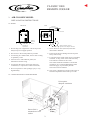
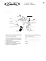
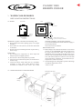
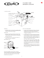
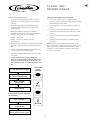
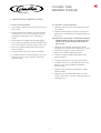
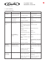
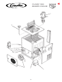
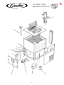
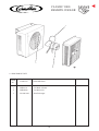
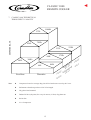
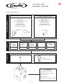
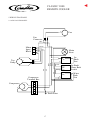
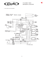
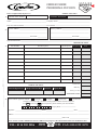
PRODUCT MANUAL
PM R01/R02 Issue 5 9/96
▼
®
CLASSIC 1000
REMOTE COOLER
®
CONTENTS
1. INTRODUCTION:
1. Introduction ............................................................. 1
IMI Cornelius has a highly versatile range of Classic
Remote Coolers, to suit a variety of applications.
2. Siting and Installation Air Cooled Model
2.1 Siting .............................................................. 2
2.2 Siting & Installation Diagram ........................ 2
2.3 Installation .................................................... 3
There are 2 basic models:
Air Cooled Classic 1000 *
Water Cooled Classic 1000 *
For each of these, a lid format can be selected with a 3
stage top mounted, water recirculation pump, giving a
nominal, dead end pressure of 1.8 bar (26 psi).
3. Siting and Installation Water Cooled Model
3.1 Siting .............................................................. 4
3.2 Siting & Installation Diagram ........................ 4
3.3 Installation .................................................... 5
Cassette coils are available, with various length options,
depending upon the quantity and type of product to be
dispensed. There is a choice of, short, long and super
long coils, to give a variety of dispense temperatures. A
maximum of 14 short or long coils can be incorporated.
Where super long coils are required, a maximum of 6
may be used. Any coil spaces not required should be
filled with coil blanks.
4. Maintenance Instructions
4.1 Air Cooled Model .......................................... 7
4.2 Water Cooled Model ..................................... 7
5. Fault Finding
5.1 Air Cooled Model .......................................... 8
5.2 Water Cooled Model ..................................... 9
Both cooler types have ice bank and temperature
controlled water bath thermostats, which can be selected
according to the operating conditions.
6. Parts List
6.1 Air Cooled Model ........................................ 11
6.2 Water Cooled Model ................................... 13
6.3 Discharge Unit ............................................. 14
The Air Cooled model will dissipate heat to its
surroundings from the fridge plant and should be
located in a well ventilated area, as close to the chilled
cellar as possible.
The Water Cooled model has a fully sealed refrigeration
system in the base unit. Heat is dissipated via a water/
glycol mixture to an exterior wall mounted Discharge
Unit. The coolant is pumped via a Recirculation Pump
which is mounted in the base unit. The Water Cooled
model can be sited in a chilled cellar, with minimal heat
output.
7. Theoretical Throughput Capacity ......................... 15
8. Selection Chart ...................................................... 16
9. Wiring Diagrams
9.1 Air Cooled Model ........................................ 17
9.2 Water Cooled Model ................................... 18
* The 1000 suffix in the product name indicates the
maximum theoretical number of pints which can be
served in a 1 hour period without a marked increase
in product temperature. It does not allow for heat loss
in the python and other assemblies.
1
▼
CLASSIC 1000
REMOTE COOLER
®
2. AIR COOLED MODEL
INSTALLATION INSTRUCTIONS
2.1 SITING
SIDE VIEW
PLAN
2.0m max
13A Socket
Install on
firm level
surface
Castors allow
movement in
any direction
100mm (minimum) clearance
required to allow adequate ventilation
1. Do not drag over rough floors or down steps and
always keep in an upright position.
7. Never allow air vents (louvres) to become
obstructed or blocked.
2. Site as near to the stored product as possible.
8. Protect from physical damage and do not place
heavy items on top.
3. Avoid siting in a chilled cellar, unless cellar cooling
is uprated by 1.5kw
9. Locate the Classic 1000 within 2m of a grounded,
switched, 13 amp, 230V socket which is easily
accessible for isolation of the cooler.
The socket should be installed to current IEE
regulations. It is recommended that the mains
electrical supply is protected by RCCB.
The Cooler must be earthed.
4. Allow access to side and front panels, for
maintenance and servicing.
5. Avoid siting the unit in warm areas with poor
ventilation (i.e. cupboards or small storerooms).
6. Prevent exposure to water spillage, spray or very
high humidity.
10. The cooler is designed to operate in the range of
ambient temperatures from 10°C up to 35°C.
2.2 SITING & INSTALLATION DIAGRAM
Unit requires
adequate ventilation
Chilled
Cellar
Remote
Cellar
Ensure Unit is
mounted on a level
surface
2
▼
CLASSIC 1000
REMOTE COOLER
®
2.3 INSTALLATION
➚
➚
15mm Ball valves
Brass tails – to be used when
recirculation lines are 1/2" I.D.
Open
Closed
Filler cap
Fill water bath here
Moulded mains
plug with 10A fuse
Flow adjuster –
remove for increased flow
Plug for pump
24v socket
Mains on indicator
Ice bank/water
bath switch
Overflow
COOL AIR
INLET
WARM AIR
EXHAUST
1. Installation must be carried out by a suitably trained
person and comply with national and local codes for
connection to the electrical supply.
5. The cooler is factory set on icebank mode. If
necessary, select water bath setting using the switch
behind the lower front panel.
2. Remove the packaging and fill the water bath with
cold mains water, to the level of the overflow. (The
cooler should not be moved once the water bath has
been filled with water.)
6. Connect product coils to product lines. Check for
leaks.
7. Connect the recirculation lines to the ball valves.
Open both valves and top up the water level where
necessary.
3. Assemble Ball Valves to pump. Ensure these are
closed. Check pump is plugged in.
8. Check the water flow. Remove the flow adjuster if
necessary.
4. Connect the 3 pin plug to the mains and switch on.
The mains on neon should illuminate.
9. Allow the cooler to build up its icebank (5 hours
minimum).
3
▼
CLASSIC 1000
REMOTE COOLER
®
3. WATER COOLED MODEL
INSTALLATION INSTRUCTIONS
3.1 SITING
SIDE VIEW
PLAN
2.0m max
13A Socket
Install on
firm level
surface
Castors allow
movement in
any direction
100mm (minimum) clearance
required to allow adequate ventilation
GENERAL (Applies to both base and discharge unit)
1. Prevent exposure to water spillage, spray or very high
humidity.
2. Never allow air vents (louvres) to become obstructed
or blocked.
3. Protect from physical damage and do not place heavy
items on top.
should be installed to current IEE regulations.
It is recommended that the mains electrical supply is
protected by RCCB.
The Cooler must be earthed.
DISCHARGE UNIT
1. The Discharge Unit should be mounted in a convenient
position on an EXTERIOR wall and provide access
for pipes and electrical cable to the Base Unit
(Maximum 30m run length from Base Unit). If no
exterior wall is available within 30 metres of the Base
Unit, then mount inside on a wall in a cool room with
plenty of fresh air ventilation. Avoid warm areas (i.e.
cupboards or small storerooms).
2. The Discharge Unit is designed to operate in the range
of ambient temperatures from
-10°C to 35°C.
BASE UNIT
1. Do not drag over rough floors or down steps and
always keep in an upright position.
2. Site as near to the stored product as possible.
3. Allow access to side and front panels, for maintenance
and servicing.
4. Locate the Classic 1000 within 2m of a grounded,
switched, 13 amp, 230v socket which is easily
accessible for isolation of the cooler. The socket
3.2 SITING & INSTALLATION DIAGRAM
Minimum bend radius
of 100mm
Do not insulate
pipework
No contact
between
pipes
Push in
fittings
Discharge
Unit
Remote
Cellar
4
▼
CLASSIC 1000
REMOTE COOLER
®
➚
➚
3.3 INSTALLATION
Direction of
glycol flow
15mm Ball valves
Brass tails – to be used when
recirculation lines are 1/2" I.D.
Open
➙
➙
Flow adjuster – remove
for increased flow
Closed
Filler cap
Moulded mains
plug with 10A fuse
Fill water bath here
Plug for pump
Glycol tank cap
24v socket
Mains on indicator
Ice bank/water
bath switch
Overflow
Pour glycol/water
mixture here
GENERAL
GLYCOL LINES/WIRING
1. Using 0.75mm2 electrical cable & plug, connect the
Discharge Unit to the Base Unit. The plug socket is
located at the rear of the cooler (Note: This is a
nominal 24 volt supply. The Base Unit 24 volt plug
is supplied with the unit).
1. Installation must be carried out by a suitably trained
person and comply with national and local codes for
connection to the electrical supply.
BASE UNIT
1. Remove the packaging and fill the water bath with
cold mains water, to the level of the overflow. The
cooler should not be moved once the water bath has
been filled with water.
2. Complete the glycol circuit by connecting the pipework
between the Base Unit and the Discharge Unit with the
aid of the fittings provided. Avoid ups and downs in
each glycol line as this may create air locks. Do not
kink or crush the tubing (minimum bend radius of
100mm) and support where necessary.
This circuit will carry hot glycol solution under
pressure, and it is important for safety reasons that
suitable tubing is used. Consult a specialist tubing
manufacturer or contact Cornelius in case of difficulty.
PVC tubing, whether braided or not, is not suitable for
this application.
The tubing ID must be sufficient to ensure a minimum
flow rate of 6 litres/minute in the glycol circuit. For a
pipe run of 30m out + 30m back, an ID of at least
11.5mm will be required.
2. Assemble Ball Valves to pump. Ensure these are
closed. Check pump is plugged in.
DISCHARGE UNIT
170
ive
ls g
hee ment
iveW ve dir
g
s
eel nt
Wh veme ir
d
170
Removable
end panel
15mm OD
header tubes
WARM AIR
EXHAUST
➙
➙
Direction of
glycol flow
Cable grip
for 24V wiring
Secure the Discharge Unit to the wall in a manner
capable of supporting the Discharge Unit weight (9Kg).
Two suitable fixing screws and rawl plugs should be
used which secure the Discharge Unit via two holes
located at the top of the unit.
5
▼
CLASSIC 1000
REMOTE COOLER
®
SYSTEM COMMISSIONING
COMPLETING THE INSTALLATION
1. It is essential the following procedure is strictly
adhered to, to ensure the glycol circuit is primed
correctly.
1. The cooler is factory set on icebank mode. If
necessary, select water bath setting using the switch
behind the lower front panel
2. Mix monopropylene glycol and water to give a
solution of 30% Glycol 70% water. Do not use
ethylene glycol.
2. Connect product coils to product lines. Check for
leaks.
3. Connect the recirculation lines to the ball valves.
Open both valves and top up the water level where
necessary.
Ensure that sufficient water/glycol mixture is
available for pouring into the reservoir tank before
switching the system on. You will need:4 litres – for the tank
4. Check the water flow. Remove the flow adjuster if
necessary.
4 litres – for every 35 metres of 12 mm
I/D glycol line.
5. Allow the cooler to build up its icebank (5 hours
minimum).
3. Disconnect one of the glycol lines from the rear of the
base unit and fill the glycol tank. Reconnect glycol
line.
NOTE There is a low temperature thermostat on the
water cooled Classic which will not allow the fan in the
Discharge Cooler to operate if the temperature of the
coolant is low. On installation, therefore, the fan may
not start for some time.
4. Connect the 3 pin moulded plug to the mains and
switch on the power to the Base Unit.
5. The base mounted coolant pump will start to prime
the system.
As the coolant level drops, keep filling the
reservoir with the mixture, ensuring it does not
drop below the minimum level. Do not allow the
base mounted coolant recirculation pump to run
dry.
Check glycol circuit is complete
Leave one fitting disconnected
Glycol tank
during
operation
▼
Fill glycol tank
Connect remaining fitting
▼
Have remaining
glycol ready
▼
Switch on cooler and
keep tank full
If circuit fails to prime eliminate
air as follows:Switch off for 30 seconds
Ensure full tank
▼
Switch on cooler and
keep tank full
▼
Note: high temp. cut-out?
Allow 4 mins for cooler restart
6
▼
CLASSIC 1000
REMOTE COOLER
®
4. MAINTENANCE INSTRUCTIONS
4.1 AIR COOLED MODEL
4.2 WATER COOLED MODEL
1. Check that the water level in the water bath is up to
the overflow.
1. Check that the water level in the water bath is up to
the overflow.
2. Check and clean the Condenser fins. Dirt and dust
can block the air vents in the condenser, severely
reducing the effectiveness of the refrigeration
system.
2. Check that the Discharge Unit fan is working and
that there are no obstructions or blockages of the air
flow vents.
N.B. The fan is controlled by a thermostat mounted
within the Base Unit. It may switch the fan off
when air into the discharge unit drops below
approx 12°C.
3. Check that there is adequate air flow through the
unit, ensuring enough space all round and that there
are no obstructions in the front of the air flow vents.
3. Check and clean the heat exchanger fins on the
Discharge Unit. Dirt and dust can block the air vents
in the heat exchanger, severely reducing the
effectiveness of the refrigeration system.
4. Check the condition and the effectiveness of the
Python insulation.
5. Check the Python for correct water recirculation.
6. At regular intervals, to be determined by the owner
and/or the user, the cooler should be checked for
electrical safety.
4. Check the condition and the effectiveness of the
Python insulation.
5. Check the Python for correct water recirculation.
6. At regular intervals, to be determined by the owner
and/or user, the cooler should be checked for
electrical safety.
7. Check the glycol lines are not kinked or crushed.
Check for leaks.
8. Check the level of coolant (Water/Glycol) in the
reservoir and re-fill as necessary with a 30% Glycol
70% Water mix.
7
▼
CLASSIC 1000
REMOTE COOLER
®
5. FAULT FINDING
5.1 AIR COOLED MODEL
PROBLEM
POSSIBLE FAULT
No Product.
Dispense system faulty.
Product too cold.
Product
consistently too
warm.
Product too
warm during
peak periods.
ACTION
Check and correct.
Product frozen in coil.
Is ice bank too large?
Check and replace thermostat
if faulty.
Long soak time in coil
and/or python.
Low throughput.
Reduce the number of taps per
product.
Coil too long.
Incorrectly specified.
Fit shorter coil.
No ice bank or water
bath too warm.
Fuse blown or no electrical
supply.
Check fuse, plug and mains
switch.
Water bath thermostat used
but ice bank thermostat
needed.
Switch to ice bank.
Water bath thermostat set
too high.
Turn thermostat down.
Thermostat failed.
Replace.
Refrigeration system failed.
Replace base.
Water recirculation pump
not plugged in.
Plug pump into socket on the
base.
Water recirculation pump
failed.
Replace.
Blockage in python.
Check for kinks. Clear out any
debris in the water recirculation
pipes.
Product coil too short.
Incorrectly specified.
Fit longer coil.
Insufficient ice being
produced or being
produced very slowly.
Poor airflow through the
condenser.
Check for space around the
cooler and airflow obstruction.
Clear and clean the condenser
fins.
Condenser fan failed or
operating incorrectly.
Replace.
Refrigeration system fault.
Replace base.
Too many coils in the cooler
for such a high demand.
Reduce the number of products
on the cooler. Fit further cooler
if necessary.
Product inlet temperature
may be too high.
Reduce the temperature of
product storage area.
No water being
recirculated through
python.
Product too
warm after a
period of time.
POSSIBLE CAUSE
Throughput too high.
8
▼
CLASSIC 1000
REMOTE COOLER
®
5.2 WATER COOLED MODEL
❖
Fault finding is very similar to the air cooled model.
❖
Follow the air cooled table on the previous page, with the additions detailed below.
PROBLEM
POSSIBLE FAULT
POSSIBLE CAUSE
ACTION
Product
consistently too
warm.
No ice bank or water
bath too warm.
No coolant in CRU. †
Refill with 30% Glycol 70%
water. Check for leaks.
Coolant pump in CRU †
failed.
Replace.
Coolant not flowing
through Discharge Cooler.
Check all the stop valves are
open. Check glycol lines are
not kinked or crushed.
Ensure pump priming
procedure is strictly adhered
to.
Discharge Cooler airflow
blocked.
Clear blockage. Clean fins as
necessary.
Discharge Cooler fan *
failed.
Replace.
Discharge Cooler airflow
blocked.
Clear blockage. Clear fins as
necessary.
Discharge Cooler fan *
failed.
Replace.
Product too
warm after a
period of time.
Insufficient ice or slow
ice build.
* N.B. The Discharge Cooler fan is controlled by a thermostat mounted
on the liquid line of the refrigeration circuit. The fan may not run
in cold ambients (approximately less than 12°C). On initial start
up (in warm conditions) the fan will not start until the liquid line is
warm.
† N.B. There is a high temperature cut-out mounted on the liquid line of
the refrigeration circuit. If temperatures become excessive, this
thermostat will cut-out the compressor. The device protects the
compressor against loss of coolant flow, loss of 24v supply and loss
of discharge unit airflow.
Both of the above thermostats are auto-reset.
9
▼
CLASSIC 1000
REMOTE COOLER
▼
CLASSIC 1000
REMOTE COOLER
®
1
10
9
8
7
5&6
4
3
2
10
®
6. PARTS LIST
6.1 AIR COOLED MODEL
ITEM
No.
PART No.
DESCRIPTION
1a
99 5500 000
Top Mounted Pump (Aquaflow)
1b
99 1000 384
Spares Pump Assy. - Marchmay
2
44 000 210
Conmpressor (Danfoss)
44 0000 218
Compressor (Embraco - Aspera)
3
2RF096A
Condenser
4
58 1000 336
Fan Door Assembly
5
58 0475 059
Control Knob
6
58 0400 075
Water Bath Stat
7
58 0440 370
Ice Bank/Water Bath Switch
8a
58 1174 007
Ice Bank Stat
8b
14 2498 000
Electronic Ice Control
9
58 0440 334
Mains Neon (Green)
10
58 0400 082
Thermometer
Not
Shown
58 1005 304
Filler Cap
2RF738A
Coil Blank
2ZU573A
Ball Valve
58 1000 310
Mains Lead and Plug Assembly
58 0480 145
Castor (this cannot be used to replace wheel)
58 0480 148
Wheel
2RF371A
Temperature Probe (for use with 14 2498 000 only)
11
▼
CLASSIC 1000
REMOTE COOLER
▼
CLASSIC 1000
REMOTE COOLER
®
1
11
13
12
10
11
8&9
7
5
6
4
3
2
12
®
6.2 WATER COOLED MODEL
ITEM
No.
PART No.
DESCRIPTION
1a
99 5500 000
Top Mounted Pump (Aquaflow)
1b
99 1000 384
Spares Pump Assy. - Marchmay
2RF150A
Heat Exchanger
58 1000 349
Heat Exchanger (barbed connector)
44 0000 210
Compressor (Danfoss)
44 0000 218
Compressor (Embraco - Aspera)
4
58 0420 560
Coolant Pump
5
2EF013A
5 Amp Fuse
6
58 1001 321
Door
7
58 1005 302
Reservoir Bottle
8
58 0475 059
Control Knob
9
58 0400 075
Water Bath Stat
10
58 0440 370
Ice Bank/Water Bath Switch
11
58 0440 239
Test Switch
12
58 0440 334
Mains Neon
13a
58 1174 007
Ice Bank Stat
13b
14 2498 000
Electronic Ice Control
14
58 0400 082
Temperature Gauge
Not
58 1005 304
Filler Cap
2RF738A
Coil Blank
2ZU573A
Ball Valve
58 1000 310
Mains Lead and Plug
58 0480 145
Castor (this cannot be used to replace wheel)
58 0440 423
Fan Control Switch
58 0440 401
High Temperature Cut-Out Switch
58 0440 395
Transformer
58 0480 148
Wheel
2RF371A
Temperature Probe (for use with 14 2498 000)
2
3
Shown
13
▼
CLASSIC 1000
REMOTE COOLER
®
1
3
2
6.3 DISCHARGE UNIT
ITEM
No.
PART No.
DESCRIPTION
1
2MP161A
Fan Blade 250mm
2
2MR400A
Fan Motor 24 v
3
58 1000 402
Heat Exchanger
14
▼
CLASSIC 1000
REMOTE COOLER
▼
CLASSIC 1000
REMOTE COOLER
®
7. CLASSIC 1000 THEORETICAL
THROUGHPUT CAPACITY
1000Pt
DISPENSE RATE
572L
428L
750Pt
133L
100L
205L
175Pt
360Pt
84Pt
48L
First Hour
Note
232Pt
Thereafter
emp
T
t
e
l
ct In13˚C p
u
d
Pro 55˚F, t Tem
utleC
O
t
c ˚
4˚C Produ 3˚F, 6
2
,
4
F
75˚
˚C
, 10
F
˚
50
❖
Compressor based on average duty plus all ice bank reserve used up in 1 hour.
❖
Performance based on product coil of ≈ 5 m length.
❖
No python load assumed.
❖
Deduct 50 litres (88 pints) for every 10 metres (33 feet) of python run.
❖
R134a Gas
❖
21 cc Compressor
15
F,
50˚
C
10˚
F,
41˚
5˚C
®
COILS
STANDARD MODEL
8. SELECTION CHART
CLASSIC 1000 WATER COOLED
CLASSIC 1000 AIR COOLED
21cc Compressor
25kg Ice Reserve
4 litres Glycol
Integral Glycol Reservoir & Pump
Mains Indicator
Water Bath Thermostat
Ice Bank Thermostat
Ice Bank/Water Bath Switch
21cc Compressor
25kg Ice Reserve
Icebank/Water bath Control
Mains Indicator
Water Bath Thermostat
Ice Bank Thermostat
Ice Bank/Water Bath Switch
Discharge
Unit
Base
Unit
+
SHORT
+
LONG
=
+
SUPER LONG
PRODUCT
COILS
14 SPACES
BLANKS
OPTIONS
N.B. Super long coil takes up two spaces
TEMPERATURE INDICATOR
PUMP
3 Stage,
Top Mounted Pump
FITTINGS
CUSTOMER FITTING KIT
LABELS & SPECIAL PARTS
BALL VALVES
BRASS TAILS
INSTALLATION INSTRUCTIONS
16
▼
CLASSIC 1000
REMOTE COOLER
▼
CLASSIC 1000
REMOTE COOLER
®
9 WIRING DIAGRAMS
9.1 AIR COOLED MODEL
E
Fan
Fan
Connector
Blue
Mains L
Input E
Block N
Top
Pump
Brown
Mains
Neon
E
Pink
G/Y
Orange
G/Y
G/Y
Blue
White
Brown
E
E
Compressor
Terminal Box
Compressor
E
L
N
E
Earth Point
17
Ice
Bank
Stat
Ice Bank/
Water Bath
Switch
Water
Bath
Stat
®
9.2 WATER COOLED MODEL
18
▼
CLASSIC 1000
REMOTE COOLER
®
Please complete fully all parts 1-4
1.
▼
ORDER FORM/
CLASSIC 1000
PROFORMA INVOICE
REMOTE COOLER
®
OFFICE USE ONLY
Customer Order Number:
Cornelius Account No.
Name: --------------------------------------------------------------- Company Name: ---------------------------------------------------------Day Time Phone Number: ---------------------------------------- Fax Number: --------------------------------------------------------------2.
Invoice Address: --------------------------------------------------
Delivery Address: -------------------------------------------------
-----------------------------------------------------------------------
-----------------------------------------------------------------------
---------------------------------------- Post Code: -----------------
---------------------------------------- Post Code: -----------------
Special Instructions: ------------------------------------------------------------------------------------------------------------------------------OFFICE USE ONLY
3.
Part Number
Qty Required Price per Unit
Part Description
Total Cost
OFFICE USE ONLY
Acknowledgement No.
Cheque Clearance Date
Cost
Due Date
Delivery
Request Date
VAT @ 17.5%
Total Order Value
IMI Cornelius standard terms & conditions of sale apply.
4.
Please indicate payment method:
Account
Cheque
Postal Order
Access/Visa
Cheques or Postal Orders should be made payable to IMI Cornelius (UK) Ltd.
For
Access or
Visa Payments, please indicate your card number.
Expiry Date: --------------------------Signature: ------------------------------------------------ Name: -------------------------------------------------- Date: -------------------Address: -------------------------------------------------------------------------------------------------------------------------------------------------------------------------------------------------------------------------------------------- Post Code: -----------------------------------Please return to: IMI CORNELIUS (UK) LTD Rawson Spring Way Riverdale Industrial Estate Sheffield S6 1PG
TEL: 0114 285 5886
ORDER
8.30 am
☎
19
HOTLINE
5.15 pm
FAX: 0114 232 1070
▼
®
IMI CORNELIUS (UK) LTD
®
Tything Road
Alcester
Warwickshire
England B49 6EU
Telephone: 01789 763101
Facsimile: 01789 400595