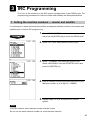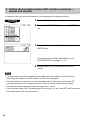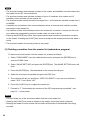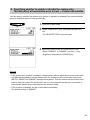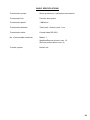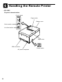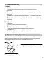
1
POS TERMINAL
MODEL
ER-A770
INTER-REGISTER
COMMUNICATION SYSTEM
INSTRUCTION
MANUAL
TABLE OF CONTENTS
Page
Introduction ............................................................................................................................... 3
Inline Operation ........................................................................................................................ 4
1. Message display ................................................................................................................ 4
(1) The message displayed during inline communications................................................ 4
(2) Error messages ............................................................................................................ 5
2. Open store operation (PGM2 mode) — master and satellite ............................................ 6
3. Close store operation (PGM2 mode) — master and satellite ............................................ 7
4. Sign-on operation (server assignment) (REG mode/MGR mode) ..................................... 8
5. Server sign-on report ......................................................................................................... 9
6. Sign-off operation (cancellation of server assignment) (REG mode/MGR mode) .......... 10
7. Look-up and updating of the GLU/PBLU file ................................................................... 11
(1) Centralized GLU/PBLU file system ............................................................................ 11
(2) Individual GLU/PBLU file system ............................................................................... 11
8. Drive-through function ...................................................................................................... 12
(1) Centralized file system ............................................................................................... 12
(2) Individual file system .................................................................................................. 12
9. T-Log polling .................................................................................................................... 14
10. Communication with a remote printer (option) ................................................................. 15
(1) Second (back-up) remote printer ............................................................................... 15
(2) Remote printer send function ..................................................................................... 16
(3) Priority printing function .............................................................................................. 16
11. Rerouting receipt/journal print data .................................................................................. 17
Consolidated and Individual Reports ...................................................................................... 18
1. Operating modes .............................................................................................................. 18
2. Job number ...................................................................................................................... 18
3. Consolidated reports — master/back-up master ............................................................. 19
(1) Report generation procedure ..................................................................................... 19
(2) List of consolidated reports (SYSTEM READING/RESETTING) ............................... 20
4. Individual reports — master/back-up master/satellite...................................................... 23
(1) Report generation procedure ..................................................................................... 23
(2) List of individual reports (READING/RESETTING) .................................................... 24
5. Server report .................................................................................................................... 26
IRC Programming ................................................................................................................... 27
1. Setting the machine numbers — master and satellite ..................................................... 27
2. Setting the terminal numbers (IRC machine numbers) — master and satellite .............. 28
3. Creating/updating the master list — master .................................................................... 29
(1) Creating the master list (subwindow program) .......................................................... 29
(2) Deleting a machine from the master list (subwindow program) ................................. 30
4. Specifying whether to enable or disable the system retry function when a
transmission error occurs — master and satellite ........................................................... 31
5. Specifying the terminal to serve as a back-up master — master .................................... 32
6. Reading the contents of the IRC programming — master and satellite .......................... 33
1
7. Downloading the contents of the IRC programming to satellites — master .................... 35
(1) Initial downloading ...................................................................................................... 35
(2) Maintenance downloading .......................................................................................... 36
8. Programming for the remote printer ................................................................................. 38
(1) Assigning kitchen printer numbers to remote printers — master and satellite .......... 38
(2) Assigning the second kitchen printer number to each remote printer — master
and satellite ................................................................................................................ 39
(3) Naming the remote printer — master and satellite .................................................... 39
(4) Specifying whether to enable or disable the function for data transmission to the
remote printer — master and satellite ........................................................................ 40
(5) Specifying the format of remote printing — master and satellite ............................... 40
(6) Specifying the format of chit printing — master and satellite ..................................... 41
9. Reading the contents of the remote printer programming — master and satellite .......... 42
10. Downloading the contents of the remote printer programming to satellites — master ... 43
11. Programming for the Manager Work Station (MWS) — master and satellite .................. 44
(1) Programming of the terminal number ......................................................................... 44
(2) Programming of the time-out time .............................................................................. 45
12. Reading the contents of the Manager Work Station (MWS) programming — master
and satellite ...................................................................................................................... 46
System Back-Up ..................................................................................................................... 47
1. How the IRC back-up system works ................................................................................ 47
2. Master declaration — when the master or back-up master breaks down ....................... 48
(1) When the master breaks down — Master declaration at the back-up master ........... 48
(2) When the back-up master breaks down — Master declaration at the master ........... 50
3. Recovery declaration — when the master or back-up master recovers from a
breakdown ........................................................................................................................ 51
(1) When the master recovers from a breakdown — Recovery declaration at the
back-up master ........................................................................................................... 51
(2) When the back-up master recovers from a breakdown — Recovery declaration
at the master ............................................................................................................... 53
Error Recovery ........................................................................................................................ 54
1. Data clear operation ......................................................................................................... 54
(1) Data clearing of the electronic journal data — master and satellite .......................... 54
(2) Data clearing of the T-LOG buffer — master and satellite ......................................... 54
(3) Data clearing of the transaction memory — master and satellite .............................. 55
(4) Data clearing of the hourly sales data memory — master and satellite .................... 55
(5) Data clearing of the daily net sales data memory — master and satellite ................. 55
(6) Data clearing of the server sign-on state — master ................................................... 56
(7) Data clearing of the GLU/PBLU data in use — master .............................................. 56
(8) Data clearing of the drive-through data in use — master .......................................... 56
2. System retry function ....................................................................................................... 57
BASIC SPECIFICATIONS ...................................................................................................... 59
Handling the Remote Printer .................................................................................................. 60
2
Introduction
The ER-A770 inter-register communication (IRC) system consists of one master machine and
up to 15 satellite machines/remote printers (max. 9 remote printers) which are all interconnected
by the Sharp Retail Network (SRN) to provide data transmission among them. This system
allows the manager to exercise centralized control over the satellites through the master.
Sharp Retail Network
Master
Satellite
Satellite
Remote Printer
(max. 9 remote printers)
Max. 15 satellites/remote printers
• One of the satellites may be used as a back-up master.
3
1 Inline Operation
1. Message display
(1) The message displayed during inline communications
1) The message shown at below is displayed at the master engaged in IRC transmission
(when the broadcasting method has been preset).
ex.:
SENDING DATA
NOTE
The above message is also displayed at the satellite which is engaged in system resetting
transmission.
2) The machine number of the satellite that is communicating with the master is
instantaneously displayed at the master after IRC transmission.
In this case, the machine number is “000022.”
ex.:
000022
4
(2) Error messages
When an error occurs, a corresponding error message is displayed.
For a description of the error messages, see the “List of error messages” below.
List of error messages
Error message (Default)
Description
BUSY
• The target machine is busy.
LACKING MEMORY
• The GLU, drive-through code, or related file memory is full.
MOTOR LOCK
• The remote printer head did not operate correctly.
NO AUTHORITY
• The server who entered a GLU/PBLU code was not authorized.
UNDEFINED CODE
• The specified server code is not present in the master.
• The entered GLU/PBLU code is not listed.
CODE NOT FREE
• The specified server has signed on at another machine.
• The entered GLU/PBLU code is in use.
POWER OFF
• The power was not turned on.
T-LOG FULL
• The T-LOG file is full.
NON RESET
• IRC initial D/L before resetting.
TYPE ERROR
• IRC Download file type mismatch.
LINE ERROR
• SRN line error.
SYSTEM CLOSED
• Entry is executed in close store state.
IS SIGNED ON
• IRC server sign-on error (when all server resetting executed).
NO REPLY/MASTER
• Master does not reply to the request.
NO REPLY/BACKUP
• Backup master does not reply to the request.
ATTEMPT RETRY?
• System retry message.
NOTE
• To clear the error message displayed, press the [CL] key.
• Please consult your authorized SHARP dealer to remedy the cause for the error condition.
5
2. Open store operation (PGM2 mode) — master and satellite
When the open store operation is performed at the master, the IRC system is opened and the
registration function becomes available at all the machines in the IRC system.
The following types of communications between the master and satellites are allowed;
From the master to the satellite
• Sending a request for the satellite to receive data (T-LOG polling)
• Sending a response to inquiry from the satellite
From the satellite to the master
• Sending a request for T-LOG polling
• Sending data to the T-LOG buffer
• Sending a request for updating of the GLU/PBLU file
• Inquiring for data on the GLU/PBLU and customer files
Open store procedure (PGM2 mode)
Select OPEN STORE from the PGM2 MODE menu and
press the [ENTER] key.
NOTE
• You can also perform the open store operation at each satellite. Once the open store
operation is performed at a satellite, you can make registrations at the satellite. When you
perform the open store operation at the satellites, T-LOG polling will not take place.
• The open store operation cannot be performed at any machines whose terminal numbers
have not been programmed.
• If a transmission error occurs when the open store operation is being performed, the master
displays and prints (journal printer) the machine number of the satellite that encountered the
error. When the master has been programmed to enable the system retry function*, a prompt
to retry the open store operation will be displayed.
* For the system retry function, please refer to pages 57 - 58.
6
3. Close store operation (PGM2 mode) — master and satellite
When the close store operation is performed at the master, the inline system is closed and the
registration function becomes unavailable at all the machines in the inline system. It should be
noted that for the close store operation, all the satellites must be in their SIGN-OFF state. After
this operation, the communications between the master and satellites which have been enabled
with the open store operation are disabled. The master, however, can download preset data and
reset the sales data at satellites.
In the close store state, any key operation in the REG or MGR mode is invalid.
Menu selection
Select CLOSE STORE from the PGM2 MODE menu and
press the [ENTER] key.
NOTE
• You can also perform the close store operation at each satellite. Once the close store
operation is performed at a satellite, you can no longer make registrations at the satellite.
• If a satellite is in the SIGN-ON state, the master encounters an error and displays the machine
number of the satellite.
• When the close store operation is performed, the data remaining in the T-LOG buffers of all
the satellites is collected by the master.
• If a transmission error occurs during the close store operation, the master displays and prints
(journal printer) the machine number of the satellite that has encountered the error.
In this case, a prompt to attempt a retry is displayed when the system retry has been enabled.
7
4. Sign-on operation (server assignment) (REG mode/MGR mode)
The sign-on operation is intended to assign a server to a machine (satellite or the master) and
enable him or her to perform entry operations at the machine.
If a server successfully signs on at a machine, his or her server name appears on the LCD of
the machine.
The server memory is under the control of the master.
The sign-on operation can be done whether the machine is in the open store or close store
state. If the sign-on operation is done at a machine that is in the close store state, registrations
cannot be made at the machine due to the close store condition.
Sign-on procedure
(This procedure is the same as for server assignment at a standalone machine.)
(using menu)
1. Press the [ENTER] key when the mode selection
menu is displayed. Enter your server code and press
the [SERV#] key.
2. The pop-up window for the secret code will open if
secret code is programmed. Enter your secret code
and press the [ENTER] key.
3. The pop-up window for the drawer number will open if
drawer number entry is compulsory. Enter your drawer
number and press the [ENTER] key.
NOTE
• The sign-on operation can be made only for one server at a time.
• If a server attempts to sign on when another server has already signed on, an entry error will
occur (when the stay-down server sign-on has been preset).
• Every server that is preset in the system can sign on at any machine.
• If a server has signed on at a machine, that server cannot sign on at any other machine in the
system until he or she signs off at the original machine.
• In case of trouble, the sign-on state can be cleared at the master. (Please consult your
authorized SHARP dealer for further details.)
8
5. Server sign-on report
A server sign-on report can be generated at the master. This report is used to determine at
which terminal each server has signed on.
Report generation procedure
1. Select “PGM2 MODE” from the mode selection menu
and press the [ENTER] key.
2. Select “INLINE READING” from the PGM2 MODE
menu and press the [ENTER] key.
3. Select “SIGN ON SERVER” from the INLINE
READING menu and press the [ENTER] key.
4. Select “DISPLAY” or “REPORT PRINTER” and press
the [ENTER] key.
Server name, server code, machine no. of
the machine at which the server has signed on
9
6. Sign-off operation
(cancellation of server assignment) (REG mode/MGR mode)
The sign-off operation is intended to cancel the assignment of a server to a machine.
The sign-off operation at a machine (master or satellite) can be done only for the servers who
have signed on at the machine and are not in the middle of a registration entry.
Sign-off procedure
Keyboard entry sequence (REG/MGR/X1/Z1/X2/Z2/PGM1/PGM2 modes)
[SERV#]
NOTE
• The sign-off operation only applies to the server who has signed on.
• If a server signs on at a machine while another server has already signed on, the latter is
automatically signed off so long as items have not yet been entered and the automatic server
sign-off system has been enabled.
For more information, please consult your authorized SHARP dealer.
10
7. Look-up and updating of the GLU/PBLU file
In the IRC system, the following two types of GLU/PBLU file allocation system are available: a
centralized system and an individual system.
(1) Centralized GLU/PBLU file system
In this system, the GLU/PBLU file exists only in the master. All satellites in the IRC system can
access the GLU/PBLU file in the master for registration.
GLU/PBLU-file-related inline communications are made for the following purposes:
• New order or reorder
• Payment entry or temporary finalization
• Bill printing
• Bill transfer/bill totalizing
• Bill separate
There are two types of GLU/PBLU data transmission.
1) The GLU/PBLU data is transmitted from the master to a satellite for GLU/PBLU file look-up
(in case of a new order/reorder). In this case, the GLU/PBLU reserve counter* is retained at
the master.
* The reserve counter reserves some records of GLU/PBLU files to prevent a “LACKING MEMORY” error in
finalization.
2) The GLU/PBLU data is transmitted from a satellite to the master for finalization of a
transaction (in case of payment entry or temporary finalization).
The data transmitted from the satellite is once saved in the GLU/PBLU data receiving file
and then in the GLU/PBLU file. In this case, the GLU/PBLU reserve counter is cleared at the
master.
If a satellite looks up the GLU/PBLU file in the master or asks the master to update the file,
the backup master performs the same process as the master.
(2) Individual GLU/PBLU file system
In this system, the master and satellites have their own GLU/PBLU files and look up them for
registration. Therefore, no inline communications are made regarding GLU/PBLU data.
11
8. Drive-through function
Depending on the setup of your system, drive-through data is either centrally controlled by the
master or Individually looked up at each terminal. For more information, please contact your
authorized SHARP dealer.
Automatic code generation
Drive-through codes are generated automatically: when the end code for a transaction is
generated, the start code for another transaction is automatically generated.
The start/end codes are programmable in the PGM mode and controlled by the master
depending upon your system setup.
Automatic look-up
As drive-through codes are temporarily finalized by pressing the [SRVC] or [FINAL] key, data for
these codes is automatically looked up in the same sequence as the code was generated.
Drive-through-related inline communications are made for the following purposes:
• New order or re-order
• Payment entry or temporary finalization
• Bill printing
(1) Centralized file system
In this system, the drive-through data is transmitted from the master to a satellite for drivethrough file look-up (in case of a new order/reorder). In this case, the drive-through reserve
counter is retained at the master.
Data is transmitted from a satellite to the master for finalization of a transaction (in case of a
payment entry or temporary finalization). The data transmitted from the satellite is then saved in
the temporary drive-through data receiving file and then in the drive-through file. In this case, the
drive-through reserve counter is cleared at the master.
(2) Individual file system
In this system, the master and satellites have their own drive-through data files. They access
their own drive-through files for new orders or reorders. The drive-through data of the master or
a satellite is saved in its drive-through file for finalization of a transaction (in case of a payment
entry or temporary finalization). Therefore, no inline communications are made regarding drivethrough data.
12
NOTE
The drive-through system provides three types of the terminal operations (Order Taker
Machine/Cashier Station Machine/Counter Machine).
For more details about the system configuration, please consult your authorized
SHARP dealer.
CAR
Cashier Station
Machine
Counter
Machine
Counter
Machine
CAR
CAR
Order Taker
Machine
Counter
Machine
13
9. T-LOG polling
All REG-mode transaction data in each satellite is saved in its T-LOG buffer. T-LOG polling is a
data collecting system in which the master collects data from the T-LOG buffers in satellites.
T-LOG polling becomes available upon open-store operation and becomes unavailable upon
close store operation.
A request for T-LOG polling is issued from the satellite to the master when the number of data
records in its T-LOG buffer exceeds a predetermined number in the open store state.
As the master detects such a request, it starts collecting the T-LOG buffer data. After collection
of the data from one satellite, the master waits for a preset time and starts collecting data from
another satellite. In T-LOG polling, the data transmitted to the master is stored in the
corresponding file.
The data flow in T-LOG polling is shown below.
Master
(4)
(1)
Satellite A
(2)
(3)
(5)
Satellite B
Satellite C
Satellite D
Polling sequence (see the figure above)
(1) Satellite A makes a request for polling.
(2) The master detects the request and starts collecting T-LOG data from satellite A.
(3) The T-LOG data is sent to the master.
(4) After receiving T-LOG data from satellite A, the master waits for a preset time.
(5) The master detects a request from another satellite (B, C or D) and starts polling for it.
If its T-LOG buffer becomes full, registration will be disallowed at a satellite when it has been
programmed for “LOCK UP,” and allowed when it has been programmed for “CONTINUE.” For
how to specify whether the registration is disabled or enabled when the T-LOG buffer becomes
full, please refer to the ER-A770 instruction manual.
14
10. Communication with a remote printer (option)
When a remote printer is included in the inline system, order data is output to the remote printer
according to preset data on the remote printer.
The remote printer is used to print all or part of the data entered at a machine. It is also called a
kitchen printer. It can also be operated at a location other than the kitchen.
If a remote printer number is assigned to a department or PLU, the information on the
department or PLU is output to the remote printer when an entry for the department or PLU is
made and the transaction is finalized at a machine.
The data which can be output to a remote printer is as follows:
1) Item text
2) Quantity*
3) Unit price*/Price*
4) Amount*
5) PLU/department code*
* Whether to print or not is selectable
(1) Second (back-up) remote printer
A second kitchen printer can be assigned to each remote printer for automatic back-up.
If an error occurs during data output to a remote printer, the data is output to the second
remote printer assigned to it.
If an error occurs during data output to the second remote printer, the data is output to the
receipt printer (the receipt printed at this printer is called a chit).
For how to specify the chit print format, see page 41.
Up to two remote printers can be preset to print data on each item (PLU or department).
If two printers are preset to print data on each item, the data is simultaneously output to
both printers.
If either of these printers encounters an error, the data is output to the backup printer.
If the backup printer encounters an error, one chit receipt is printed.
15
(2) Remote printer send function
This function allows partial food orders to be sent to the remote printers.
Which printer to receive the order is selectable.
The function is intended to allow the cooking staff to begin preparing certain items before
the entire order is given.
*Case 1)
(Item entry)
NK
**Case 2)
NK: 1-9
SEND ORDER
*Case 1)
A partial food order is sent to one or several remote printers which has been specified by
the department/PLU programming.
**Case 2)
A partial food order is sent to the remote printer specified by the system presets.
(3) Priority printing function
It is desirable for the cooking staff to see the order items that require the longest cooking
time at the top of the kitchen chit. This function can send food items in the programmed
order of priority by assigning PLUs to priority groups (1 - 9).
If an error occurs in data output to a remote printer, a corresponding error message
appears on the display and the data output to the remote printer is printed on the chit
receipt.
For remote printer error messages, see page 5.
16
11. Rerouting receipt/journal print data
In restaurant environments, terminals may or may not need a receipt/journal printer.
One external printer connected by RS-232 cable can be shared by two or more ER-A770
machines.
Print data rerouting chart
Rerouting data flow
Print data (1)
ER-A770
External printer
Print data (1)
ER-A770
Ordinary data flow
Print data (2)
External printer
ER-A770
via Sharp Retail Network
via RS-232 cable
17
2 Consolidated and Individual Reports
The system can generate two types of sales reports: consolidated reports (reports on all or
specified machines in the system) and individual reports (reports on an individual machine). At
the master, you can generate consolidated reports on all or specified satellites and reports on
the master itself. At each satellite, you can generate certain reports on the satellite.
1. Operating modes
X1 mode:
Z1 mode:
X2 mode:
Z2 mode:
OP XZ mode:
Daily sales reading reports.
Daily sales resetting reports.
Periodic consolidation reading reports.
Periodic consolidation resetting reports.
Individual server daily sales reading (X) and resetting (Z) reports.
2. Job number*
Each job number is expressed as “XYnn” according to the table below.
Job number: XYnn
Entry
X
Y
nn
Category of report
0
Individual report
1
Consolidated report
0
Server report in the OP XZ mode
1
Daily sales report (X1 or Z1)
2
Periodic sales report (X2 or Z2)
Item code*
* An item code corresponds to the lower two digits of each job number listed in the tables on the
following pages.
18
3. Consolidated reports — master/back-up master
(1) Report generation procedure
To generate respective reports, use the following procedure, referring to the list of
consolidated reports on the following pages.
1. Select the required operating mode (OP XZ, X1, Z1,
X2, or Z2) from the mode selection menu and press
the [ENTER] key.
2. Select SYSTEM and press the [ENTER] key.
3. Select the type of report you wish to generate and
press the [ENTER] key. (If the desired type of report is
not listed on the display, scroll up or down the
screen.)
4. If you need to enter data to generate the report, follow
the instructions given on the display for entry.
19
(2) List of consolidated reports (SYSTEM READING/RESETTING)
These reports can be printed on the printer unit (option) or shown on the display screen.
Operating modes
Report type
DEPARTMENT
Description
OP XZ X1 Z1
X2 Z2
Job #
Required data/Remarks
Full department
report
1110
Individual dept.
group report
1112
DEPT. GROUP
TOTAL
Dept. group total
report
1113
M-DOWN FOR
DEPT.
Department
markdown report
1119
PLU
PLU report by
specified range
1120
PLU BY DEPT
PLU report by
associated dept.
1121
Individual PLU
specified report
1122
PLU GROUP TOTAL PLU group total
report
1123
PLU STOCK
PLU stock report
1124
PLU no.
PLU COST
PLU cost report
1125
PLU no.
DEPT. IND. GROUP
PLU IND. GROUP
1210
Group no. (0 thru 9)
1212
1213
1219
PLU no.
(To specify a PLU no range,
1220 enter start and end PLU nos.)
Department no.
1221
Group no.
1222
1223
1225
1126
Amount or quantity can be
selected.
1226
Amount or quantity can be
selected.
PLU zero sales
report
1127
All PLUs of zero sales.
PLU zero sales
report by specified
dept.
1127
PLU MIN. STOCK
PLU minimum
stock report
1128
PLU HOURLY
GROUP
Hourly PLU group
report
1129
TRANSACTION
Transaction report
1130
PLU TOP 20
PLU ZERO SALES
PLU top-20 report
1227
1227
1230
20
PLUs of zero sales by
department
Operating modes
Report type
Description
OP XZ X1 Z1 X2 Z2
Job #
CID
Cash-in-drawer
report
1131
TAX
Tax report
1133
Required data/Remarks
For all servers
1233
ALL SERVER
Full server report
1140
1240
IND. SERVER
Individual server
report
1041
1141
1241
ALL MANAGER
IND. MANAGER
EMPLOYEE
Full manager
report
1148
Individual manager
report
1149
Employee report
1155
specified range
1248
Manager no.
1249
1255
Employee code.
(The range can be specified by
entering start and end codes.)
EMP. ADJUSTMENT Employee
adjustment report
1256
Employee code.
(The range can be specified by
entering start and end codes.)
EMP. ACTIVE STS.
Employee active
status report
1157
Employee code.
(The range can be specified by
entering start and end codes.)
EMPLOYEE SALES
Detailed employee
sales report
1258
(Detailed cleared)
EMPLOYEE SALES
Full employee
sales report
1259
(All reset)
HOURLY
Hourly report
1160
Use the military time
(24-hour) system. For
example, to set 2:30 a.m.,
enter 230; and to set 2:30
p.m., enter 1430.
1160
For all 48 half-hours with
zero skipped
LABOR COST%
Labor cost
percentage report
1161
OVER TIME
Employee over
time report
1162
EMPLOYEE
SUMMARY
Employee
summary report
1265
Employee no.
PAY PERIOD
Pay period report
1266
Employee no.
PAY PERIOD SUM.
Pay period
summary report
1267
Employee no.
Employee no.
1262
21
Operating modes
Report type
OP XZ X1 Z1
X2 Z2
Job #
Required data/Remarks
DAILY NET
Daily net report
1270
INGREDIENT
STOCK
Ingredient stock
report
1175
Ingredient table no.
GLU
GLU report
1180
GLU/PBLU code.
(The range can be
specified by entering start
and end codes.)
GLU BY SERVER
GLU report by
server
1181
CLOSED GLU
Closed GLU report
1182
CL-GLU BY SERVER Closed GLU report
by server
1183
DRIVE THRU
Drive-through code
report
1185
D-THRU BY SERVER Drive-through code
report by server
1186
CLOSED D-THRU
Closed drivethrough report
1187
CL-DT BY SERVER
Closed drivethrough report by
server
1188
SERVICE TIME
Drive-through
service time report
1189
STACKED REPORT
Stacked report
(X1/Z1)
1190
Stacked report 1
1191
Stacked report 2
Stacked report
(X2/Z2)
1290
Stacked report 1
1291
Stacked report 2
STACKED REPORT
22
Description
Bill no.
(The range can be
specified by entering start
and end codes.)
Drive-through code.
(The range can be
specified by entering start
and end codes.)
Bill no.
(The range can be
specified by entering start
and end numbers.)
4. Individual reports — master/back-up master/satellite
(1) Report generation procedure
To generate respective reports, use the following procedure, referring to the list of individual
reports on the following pages.
1. Select the required operating mode (OP XZ, X1, Z1,
X2 or Z2) from the mode selection menu and press
the [ENTER] key.
2. Select INDIVIDUAL and press the [ENTER] key.
3. Select the type of report you wish to generate and
press the [ENTER] key. (If the desired type of report is
not listed on the display, scroll up or down the
screen.)
4. If you need to enter data to generate the report, follow
the instructions given on the display for entry.
23
(2) List of individual reports (READING/RESETTING)
These reports can be printed on the printer unit (option) or shown on the display screen.
Operating modes
Report type
DEPARTMENT
Description
OP XZ X1 Z1
X2 Z2
Job #
Full department
report
110
Individual dept.
group report
112
DEPT. GROUP
TOTAL
Dept. group total
report
113
M-DOWN FOR
DEPT.
Department
markdown report
119
PLU
PLU report by
specified range
120
DEPT. IND. GROUP
PLU BY DEPT
PLU IND. GROUP
Required data/
Remarks
MA,
SL
210
212
Group no.
(0 thru 9)
MA,
SL
MA,
SL
213
MA,
SL
219
220
PLU no.
(The range can be specified by
entering start and end codes.)
MA,
SL
PLU report by
associated dept.
121
Department no.
MA,
SL
Individual PLU
group report
122
Group no.
(0 thru 9)
MA,
SL
221
222
PLU GROUP TOTAL PLU group total
report
123
PLU STOCK
PLU stock report
124
PLU no.
(The range can be specified by
entering start and end codes.)
PLU COST
PLU cost report
125
PLU no.
MA,
SL
Amount or quantity
can be selected.
MA,
SL
All PLUs of zero
sales
MA,
SL
PLUs of zero sales
by department
MA,
MA
223
225
PLU TOP 20
PLU top-20 report
126
226
PLU ZERO SALES
MA,
SL
PLU zero sales
report
127
PLU zero sales
report by specified
dept.
127
PLU MIN. STOCK
PLU minimum
stock report
128
PLU HOURLY
GROUP
Hourly PLU group
report
129
MA,
SL
TRANSACTION
Transaction report
130
MA,
SL
227
227
230
Notes* : MA → Master, SL → Satellite
24
Notes*
SL
MA
Operating modes
Report type
TAX
Description
Tax report
OP XZ X1 Z1 X2 Z2
Job #
Required data/
Remarks
133
MA,
SL
233
ALL MANAGER
IND. MANAGER
HOURLY
Full manager
report
148
Individual manager
report
149
Hourly report
Notes*
MA,
SL
248
Manager no.
MA,
SL
160
For an individual
time range
MA,
SL
160
For all 48 half-hours
with zero skipped
MA,
SL
249
DAILY NET
Daily net report
270
MA, SL
INGREDIENT
STOCK
Ingredient stock
report
175
Ingredient table no.
GLU
GLU report
180
GLU/PBLU code.
(The range can be specified by
entering start and end codes.)
GLU BY SEVER
GLU report by
server
181
CLOSED GLU
Closed GLU report
182
CL-GLU BY SERVER
Closed GLU report
by server
183
DRIVE THRU
Drive-through code
report
185
D-THRU BY SEVER
Drive-through code
report by server
186
CLOSED D-THRU
Closed drivethrough report
187
CL-DT BY SEVER
Closed drivethrough report by
server
188
MA,
SL
SERVICE TIME
Drive-through
service time report
189
MA,
SL
STACKED REPORT
Stacked report
(X1/Z1)
190
191
Stacked report 1
Stacked report 2
MA, SL
MA, SL
STACKED REPORT
Stacked report
(X2/Z2)
290
291
Stacked report 1
Stacked report 2
MA, SL
MA, SL
MA,
SL
MA,
SL
MA,
SL
Bill no.
(The range can be specified by
entering start and end codes.)
MA,
SL
MA,
SL
Drive-through code.
(The range can be specified by
entering start and end codes.)
MA,
SL
MA,
SL
Bill no.
(The range can be specified by
entering start and end codes.)
MA,
SL
Notes* : MA → Master, SL → Satellite
25
5. Server report
At the master, you can generate consolidated transaction reports on all servers or individual
servers by reading or resetting operation.
At each satellite, you can generate consolidated transaction reports on individual servers by
reading or resetting operation.
If a specific server is signed on at a machine when resetting operation for a consolidated
individual server report is made at the machine, the data on transactions being handled by the
server is also added and printed out.
If that server is signed on at another machine, the message “IS SIGNED ON” is displayed, thus
the resetting operation for that server cannot be made.
Full server report sample
Date
Machine no.
Consecutive no.
Time
Server name and code
Job code
Report mode
Report type
Reset counter
Server code
Data on server #0001
Data on server #0002 signed on
at machine no.000002
26
3 IRC Programming
First, turn on the machines in the IRC system and place them in the PGM2 mode. The
programming procedures for both the master and satellites will be explained below.
1. Setting the machine numbers — master and satellite
It is necessary to insure that each terminal has an assigned machine number to the master and
satellites prior to further IRC programming.
1. Select “PGM2 MODE” from the mode selection menu
and press the [ENTER] key to enter the PGM2 mode.
2. Select “SETTING” and press the [ENTER] key.
3. Select “TERMINAL” and press the [ENTER] key.
Select “MACHINE#” from the REGISTER menu and
press the [ENTER] key.
4. Enter a machine number and press the [ENTER] key.
Machine number: up to 6 digits (0 - 999999)
5. Repeat steps 1 to 4 for all machines in the IRC
system.
NOTE
In an IRC network, each machine number must be unique.
Do not use the same machine number for more than one machine.
27
2. Setting the terminal numbers (IRC machine numbers) —
master and satellite
It is assumed that your terminal’s setting for inline operations has been performed.
1. Enter the PGM2 mode.
2. Select “INLINE SETTING” and press the [ENTER]
key.
3. Enter a terminal number (0 - 254) and press the
[ENTER] key.
(For programming for BMA MACHINE No. and
SYSTEM RETRY, see pages 31 - 32.)
4. Repeat steps 1 to 3 for all machines in the IRC
system.
NOTE
• Terminal numbers must be assigned to the master and each satellite in the IRC system.
(For setting the master’s terminal number, see the next paragraph.)
• If an inline network contains two or more machines with the same terminal number, IRC
communications will not be achieved correctly. Each terminal number must be unique.
• The terminal number should be within the range from 1 to 254.
• If the terminal number “000” is programmed for a machine, it is put in the OFF LINE mode and
cannot take part in IRC communications.
28
3. Creating/updating the master list — master
(1) Creating the master list (subwindow program)
This may only be performed on the pre-designated master.
1. Enter the PGM2 mode.
2. Select “INLINE SETTING” and press the [ENTER]
key.
3. Enter a terminal number (0 - 254) for the master and
then carry out the programming for other INLINE
SETTING items and press the [ENTER] key. The
subwindow for the creation of the master list will open.
(For programming for BMA MACHINE No. and
SYSTEM RETRY, see pages 31 - 32.)
4. Enter the terminal number (1 - 254) for each machine
in the IRC system (for the master and satellites) and
press the [ENTER] key. The subwindow for machine
number entry will open.
5. Enter the machine number (1 - 999999) that
corresponds to the previously entered terminal
number and press the [ENTER] key.
6. Repeat steps 4 to 5 for all machines in the IRC
system. Press the [CA/AT] key to complete the master
list.
7. Proceed to “7. Downloading the contents of the IRC
programming to satellites”, see page 35 — Inline
preset.
29
NOTE
• The terminal numbers and machine numbers of the master and satellites must be entered into
the master list for IRC communications.
• The terminal numbers and machine numbers of up to 16 machines (one master and 15
satellites) can be entered into the master list.
• The terminal number should be within the range from 1 to 254 and the machine number from 1
to 999999.
• A satellite can not perform inline communications unless its terminal and machine numbers
are present in the master list.
• If a machine number which already exists in the master list is entered, a entry error will occur
even when the corresponding terminal number does not exist in the list.
• Pressing the [ENTER] key enters the programmed terminal numbers and machine numbers
on the master. Pressing the [CA/AT] key issues a receipt on the receipt/journal printer when it
exists.
• The terminal numbers for remote printers is not preset.
(2) Deleting a machine from the master list (subwindow program)
To delete a terminal number from the master list, proceed as follows:
1. Select “PGM2 MODE” from the mode selection menu and press the [ENTER] key to
enter the PGM2 mode.
2. Select “INLINE SETTING” and press the [ENTER] key. The INLINE SETTING menu will
open.
3. Press the [ENTER] key. The subwindow for the master list will open.
4. Select the terminal to be deleted and press the [DEL] key.
5. The machine will ask you as follows: “ARE YOU SURE?” If you are sure to delete it,
select “YES.” If not, select “NO.”
6. Press the [CA/AT] key to complete the master list.
7. Proceed to “7. Downloading the contents of the IRC programming to satellites”, see
page 35 — Inline preset.
NOTE
• You can delete any of the terminal numbers that are in the master list.
• Pressing the [CA/AT] key issues a receipt on the receipt and journal printer (optional).
• Deleting the master from the master list will inhibit all requests of the satellites from being
serviced.
30
4. Specifying whether to enable or disable the system retry
function when a transmission error occurs — master and satellite
You can specify whether the system retry function is disabled or enabled if the communication
between machines does not end successfully.
1. Enter the PGM2 mode.
2. Select “INLINE SETTING” and press the [ENTER]
key.
The INLINE SETTING menu will open.
3. Move the cursor to the “SYSTEM ENTRY” line.
Select “DISABLE” or “ENABLE” with the [ • ] key
(toggle key) and press the [ENTER] key.
NOTE
• If the system retry function is enabled, a transmission job with which an error has occurred is
not finalized immediately, but the master waits for selection of one of the three commands
(RETRY, ABORT and IGNORE) through the keyboard. Then the master retries access to the
satellite that has caused the transmission error or terminates the access as a successful or
unsuccessful transmission depending on the selection made.
• If the function is disabled, the job is terminated immediately.
• The default setting is “ENABLE.”
31
5. Specifying the terminal to serve as a back-up master — master
You can assign one satellite to the function of a back-up master. If the master fails during guest
check operation, the assigned terminal will perform the master’s function.
A machine number within the range from 1 to 999999 can be entered.
If zero is entered, there will be no back-up master in the IRC system.
This job can be done in the INLINE SETTING window of the master.
The default setting is 0 (no back-up master).
1. Enter the PGM2 mode.
2. Select “INLINE SETTING” and press the [ENTER]
key.
The INLINE SETTING menu will open.
3. Move the cursor to the “BMA MACHINE No.” line.
Then enter the machine number of the terminal to
serve as a back-up master and press the [ENTER]
key.
Important note:
To insure which satellite should be selected and to
perform additional set up requirements, please consult
your authorized SHARP dealer.
NOTE
The DECLARATION functions in the PGM2 mode enable the back-up master or the master to
declare to be the master when the master or back-up master breaks down, and inform satellites
of the master’s or back-up master’s recovery.
For details of these functions, see “Master declaration” and “Recovery declaration” on pages 48
- 53.
32
6. Reading the contents of the IRC programming — master and satellite
1. Enter the PGM2 mode.
2. Select “INLINE READING” and press the [ENTER]
key.
The INLINE READING menu will open.
3. Select “INLINE PRESET” and press the [ENTER] key.
4. Select “DISPLAY” or “REPORT PRINTER” and press
the [ENTER] key.
33
Terminal number of the satellite
Terminal number of the master
System retry function
(enable/disable)
List of the machines involved in the IRC system
(terminal no./machine no.)
System retry function
(enable/disable)
Back-up master
(terminal no./machine no.)
• You can also read the same contents of the IRC Programming on the display screen.
34
7. Downloading the contents of the IRC programming to
satellites — master
When you have completed or changed the IRC programming, distribute the IRC preset data
from the master to all satellites in the IRC system.
(1) Initial downloading
For initial setup of the IRC system, use this downloading method. The preset data in the
master is downloaded to each satellite, when the existing preset data in the satellite is
cleared.
1. Enter the PGM2 mode.
2. Select “INITIAL D/L” and press the [ENTER] key.
The INITIAL D/L menu will open.
3. In order to distribute all preset data files in the master
to satellites, select “ALL PGM” and press the [ENTER]
key.
In order to distribute an individual preset data file,
select the corresponding item and press the [ENTER]
key.
For initial downloading of PLU preset data, it is
necessary to enter the code range and machine
numbers to receive the data.
NOTE: “25 ALL PGM” will clear the satellite’s
totalizers.
4. If you wish to download the IRC programming data to
all satellites, select “ALL” and press the [ENTER] key.
If you wish to download the data to certain satellite(s),
select “MACHINE SELECT” and press the [ENTER]
key. In this case, the “MACHINE SELECT” menu will
open. Move the cursor to the machine numbers and
select “YES.”
NOTE
Check the contents of the programming of all the satellites in the IRC system that have received
the preset data.
35
(2) Maintenance downloading
To update preset data for the IRC system, use this downloading method. The preset data in
the master is downloaded to each satellite without clearing the existing preset data or
totalizers.
1. Enter the PGM2 mode.
2. Select “MAINTENANCE D/L” and press the [ENTER]
key.
The MAINTENANCE D/L menu will open.
3. Select a preset data item for maintenance and press
the [ENTER] key.
If needed, enter the code range.
4. If you wish to download the IRC programming data to
all satellites, select “ALL” and press the [ENTER] key.
If you wish to download the data to certain satellite(s),
select “MACHINE SELECT” and press the [ENTER]
key. In this case, the “MACHINE SELECT” menu will
open. Move the cursor to the machine numbers and
select “YES.”
36
List of downloading jobs (PGM2 mode)
Menu
Job # Item
Description
Note
INITIAL D/L
4100
DEPT
Department preset data
Preset data copying with clearing
4119
DIRECT KEY
MAINTENANCE
D/L
NOTE
4200
4218
4220
4222
4223
4225
4226
4227
4228
4232
4300
4409
4450
4600
Dept./PLU key preset data
for direct depts./PLUs
PLU
PLU/Link PLU
PLU MENU KEY
PLU menu key preset data
LINK PLU
Link PLU preset data
PLU STOCK
PLU stock q’ty data
CONDIMENT
Condiment PLU preset data
MIX & MATCH
Mix & Match preset data
RECIPE
Recipe preset data
INGREDIENT
Ingredient preset
COMBO MEAL
Combo meal preset data
INGREDIENT STOCK Ingredient stock q’ty data
TRANSACTION
Transaction preset data
SERVER SIGN OFF All server sign off
MANAGER
Manager preset data
OPTION
Other preset data
4610
4614
DATE/TIME
LOGO
4634
4700
4800
4900
4950
4990
4999
DEF. MENU LEVEL
TAX
ONLINE PRESET
INLINE PRESET
KP PRESET
DEVICE ASSIGN
ALL PGM
5100
5110
5200
5210
5220
5222
5223
5225
5226
5227
5228
5232
5300
Date, time
Logo text preset data
Default menu level preset data
Tax preset data
Online preset data
Inline preset data
Remote printer preset data
Device assign preset data
All PGM-mode preset data
(Excepting job #4222, 4232
and 4409)
DEPT
Department preset data
DEPT PRICE
Department price preset data
PLU
PLU/Link PLU
PLU PRICE
PLU price preset data
LINK PLU
Link PLU preset data
PLU STOCK
PLU stock q’ty data
CONDIMENT
Condiment PLU preset data
MIX & MATCH
Mix & Match preset data
RECIPE
Recipe preset data
INGREDIENT
Ingredient preset data
COMBO MEAL
Combo meal preset data
INGREDIENT STOCK Ingredient stock q’ty data
TRANSACTION
Transaction preset data
Preset data copying with clearing
Preset data copying with clearing
Preset data copying with clearing
Preset data copying with clearing
Preset data copying with clearing
Preset data copying with clearing
Preset data copying with clearing
Preset data copying with clearing
Preset data copying with clearing
Preset data copying with clearing
Preset data copying with clearing
Preset data copying with clearing
Programming Job #2324,
2615 - 2621, 2630 - 2632, 2900
Preset data copying with clearing
Programming Job #2614, 2642,
2643 and 2646
Preset data copying with clearing
Preset data copying with clearing
Preset data copying with clearing
Preset data copying with clearing
Preset data copying with clearing
Preset data copying with clearing
Downloading of Job #4000 to
4990 is performed collectively.
Only preset data copying
Only preset data copying
Only preset data copying
Only preset data copying
Only preset data copying
Only preset data copying
Only preset data copying
Only preset data copying
Only preset data copying
Only preset data copying
Only preset data copying
Only preset data copying
Only preset data copying
• The PLU/LINK PLU file (INITIAL D/L and MAINTENANCE D/L) does not include stock data.
• The OPTION file includes the following data:
Optional feature preset, scale preset, hourly report, stacked report, secret code, auto
key, location preset, GLU range.
• The LOGO file includes the following data:
Logo text and bill logo, dept. group text, PLU group text, hourly group text, currency
descriptor.
• The PLU/LINK PLU file (INITIAL D/L and MAINTENANCE D/L) includes LINK PLU preset data.
• The INLINE PRESET file include MWS preset data.
• Initial D/L job #4999 should not be performed when totals exist in the system. (The totalizers
of the receiving satellite are erased.)
• Performed individual initial D/L jobs will result in a non-reset error when totals exist in the
satellites.
37
8. Programming for the remote printer
For connection of remote printers to the SRN, be sure to contact your dealer.
(1) Assigning kitchen printer numbers to remote printers — master and
satellite
With the following procedure, you can do programming for the remote printers connected to
the SRN. For initial setup of remote printers, please contact your authorized SHARP dealer.
1. Enter the PGM2 mode.
2. Select “KP SETTING” and press the [ENTER] key.
The KP SETTING menu will open.
3. Select the kitchen printer number to be programmed.
4. Carry out the programming for the remote printer.
(See the following pages for programming for
individual remote printer items.)
• Be sure to consult your authorized SHARP dealer for
the correct settings.
5. After programming for the remote printer, press the
[ENTER] key.
38
(2) Assigning the second kitchen printer number to each remote printer —
master and satellite
With the following procedure, you can assign a second remote printer to which data should
be output when the first remote printer encounters an error during transmission of that data.
This assignment is made to prepare for remote printer disconnection due to printer
breakdown or other troubles.
After the KP SETTING menu appears, proceed as follows:
1. Move the cursor to the “SECOND KP” line and enter
the second kitchen printer number.
2. Press the [ENTER] key to finish the programming for
the remote printer.
(3) Naming the remote printer — master and satellite
The programmed name will be printed together with other data on the remote printer.
This enables exact identification of the printout if the remote printer fails.
After the KP SETTING menu appears, proceed as follows:
Move the cursor to the “NAME” line and enter a desired
name for the remote printer.
39
(4) Specifying whether to enable or disable the function for data
transmission to the remote printer — master and satellite
If a remote printer is disconnected from the IRC system or any other problem occurs in it,
you can disable your machine to stop data transmission to the remote printer. This prevents
any error message from appearing on the machine display each time an entry to be
transmitted to that printer is made.
Move the cursor to the “TRANSMISSION” line and select
“DISABLE” or “ENABLE” with the [ • ] key (toggle key) or
display the choices by pressing the [SBTL] key.
(5) Specifying the format of remote printing — master and satellite
With the following procedure, you can specify what items to be printed on the remote
printer.
1. Move the cursor to the following printing format items
and select PRINT or SKIP with the [ • ] key (toggle
key) or display them by pressing the [SBTL] key.
Printing when quantity is one:
PLU/department code:
Unit price
Amount:
PRINT/SKIP
PRINT/SKIP
PRINT/SKIP
PRINT/SKIP
The default setting for these items is SKIP.
2. Press the [CA/AT] key to finish the programming for
the remote printer. The CHIT FORMAT window will
open.
(For programming for CHIT FORMAT, see the next
paragraph.)
40
(6) Specifying the format of chit printing — master and satellite
If so desired, each PLU/department item may be preset to output to the receipt printer in a
chit format.
With the following procedure, you can specify what items to be printed on chits.
1. After programming for the KP PRESET items, press
the [ENTER] key.
2. Move the cursor to the following CHIT FORMAT items
and select PRINT or SKIP with the [ • ] key (toggle
key).
Printing when quantity is one:
PLU/department code:
Unit price:
Amount:
PRINT/SKIP
PRINT/SKIP
PRINT/SKIP
PRINT/SKIP
The default setting for these items is SKIP.
3. Press the [ENTER] key to finish the programming for
chit printing.
41
9. Reading the contents of the remote printer programming —
master and satellite
1. Enter the PGM2 mode.
2. Select “KP READING” and press the [ENTER] key.
3. Select “DISPLAY” or “REPORT PRINTER” and press
the [ENTER] key.
KP no.
K.P name
Data transmission: OK/NO
Second KP no.
KP. Print format
Chit print format
42
10. Downloading the contents of the remote printer
programming to satellites — master
When you have completed the remote printer programming, you can distribute the preset data
from the master to all satellites in the IRC system.
1. Enter the PGM2 mode.
2. Select “INITIAL D/L” and press the [ENTER] key.
3. The INITIAL D/L menu will open. Select “KP PRESET”
and press the [ENTER] key.
4. If you wish to download the KP PRESET data to all
satellites, select “ALL” and press the [ENTER] key. If
you wish to download the data to certain satellite(s),
select “MACHINE SELECT” and press the [ENTER]
key. In this case, the MACHINE SELECT menu will
open. Move the cursor to the machine numbers and
select “YES.”
NOTE
Check if all the satellites in the IRC system have received the preset data for the remote printer.
43
11. Programming for the Manager Work Station (MWS)
— master and satellite
The SRN interface for the ER-A770 POS enables the ER-A770 to perform in-line
communications to a host P.C. through the connection to a Manager Work Station (MWS).
The function of Manager Work Station:
1) Down load of the terminal data
2) Up load of the terminal data
3) Remote Job Entry (RJE) function
4) T-Log function
5) ELECTRONIC MAIL function
[Terminal
[Terminal
[Terminal
[Terminal
[Terminal
PC]
PC]
PC]
PC]
PC]
(1) Programming of the terminal number
The terminal number of MWS can be specified by the following procedure:
1. Enter the PGM2 mode.
2. Select “MWS SETTING” and press the [ENTER] key.
The MWS SETTING window will appear.
3. Enter the terminal number (1 - 254) of MWS and press
the [ENTER] key.
44
(2) Programming of the time-out time
The time-out value for receiving the data can be specified by the following procedure:
1. Enter the PGM2 mode.
2. Select “MWS SETTING” and press the [ENTER] key.
The MWS SETTING window will appear.
3. Enter the time-out time (1 - 255 (sec)) and press the
[ENTER] key.
NOTE:
This value will depend upon the application. Please
consult your authorized SHARP dealer.
45
12. Reading the contents of the Manager Work Station (MWS)
programming — master and satellite
1. Enter the PGM2 mode.
2. Select “MWS READING” and press the [ENTER] key.
3. Select “DISPLAY” or “REPORT PRINTER” and press
the [ENTER] key.
Terminal No. (001)
Time-out time (7 sec)
46
4 System Back-Up
1. How the IRC back-up system works
The IRC system incorporates a back-up system.
One of the satellites can be designated to serve as a back-up master.
When both the master and back-up master are in order, the system works in the following
sequence:
(1) Each satellite sends updated GLU/PBLU data to the master.
(2) The master receives the data, processes it and sends it back to the satellite.
(3) The satellite sends the updated data to the back-up master.
(4) The back-up master receives the data, processes it and sends it back to the satellite.
Master
Back-up master
(Processing)
(Processing)
(1) Updated data
(3) Updated data
(2) Processed data
(4) Processed data
Satellite
If the master breaks down, the back-up master serves as the master after a master declaration
is made at the back-up master. If the back-up master breaks down, updated data transmission
to it can be stopped by a master declaration at the master. When the master or back-up master
recovers from the breakdown, it resumes its function as the master or back-up master by the
recovery declaring operation.
47
2. Master declaration
— when the master or back-up master breaks down
When the master or back-up master breaks down, the master declaration procedure should be
taken to inform satellites of the breakdown.
(1) When the master breaks down — Master declaration at the back-up
master
1) A satellite detects a breakdown of the master through the system retry function when it is
sending updated GLU/PBLU data to the master. At this point, the message “NO REPLY/
MASTER” appears in the pop-up window of the display.
NO REPLY/MASTER
* For the system retry function, see pages 57 - 58.
2) The master declaration operation must be done at the back-up master. This operation
informs the other satellites that the master has broken down and the back-up master will
serve as the master hereafter. (During this process, no other operation cannot be done
at each satellite.)
3) Each satellite in the IRC system starts sending updated GLU/PBLU data to the back-up
master.
4) The back-up master processes the received data and sends back the processed data to
each satellite.
Flow of a master declaration at the back-up master
Master
Back-up master
2) Master
declaration
(Processing)
Satellite
1) Detection of a breakdown
(Transmission stops.)
3) Updated data
4) Processed data
Master declaration
48
The master declaration procedure is as follows:
1. Select “PGM2 MODE” from the mode selection menu
and press the [ENTER] key.
2. Select “DECLARATION” and press the [ENTER] key.
3. Select “MASTER DECLARE” and press the [ENTER]
key.
49
(2) When the back-up master breaks down — Master declaration at the
master
1) A satellite detects a breakdown of the back-up master through the system retry function
when it is sending updated GLU/PBLU data to both the master and back-up master. At
this point, the message “NO REPLY/BACKUP” appears in the pop-up window of the
display.
NO REPLY/BACKUP
2) The master declaration operation must be done at the master. This operation causes the
master to inform all satellites of the breakdown of the back-up master.
3) Each satellite in the IRC system sends updated GLU/PBLU data only to the master.
4) The master processes the received data and sends back the processed data to each
satellite.
Flow of a master declaration at the master
Master
Back-up master
2) Master declaration
(Processing)
1) Detection of a master breakdown
(Transmission stops.)
Satellite
3) Updated data
4) Processed data
The master declaration procedure is the same as “(1) When the master breaks down.”
50
3. Recovery declaration — when the master
or back-up master recovers from a breakdown
When the master or back-up master recovers from a breakdown, the recovery declaration
operation should be taken to inform satellites of the recovery.
(1) When the master recovers from a breakdown — Recovery declaration at
the back-up master
1) The recovery declaration operation is done at the back-up master.
2) Each satellite stops sending updated GLU/PBLU data to the back-up master.
3) The back-up master sends the updated GLU/PBLU data files to the master.
4) The back-up master informs all satellites of the master’s recovery.
5) The satellites restart sending updated GLU/PBLU data to the master.
Flow of a recovery declaration at the back-up master
Master
Back-up master
1) Recovery
declaration
operation
3) Updated data file
Satellite
5) Restart of updated
data transmission
(Processing)
4) Master
recovery
information
2) Transmission stops.
Master declaration
51
The recovery declaration procedure is as follows:
1. Select “PGM2 MODE” from the mode selection menu
and press the [ENTER] key.
2. Select “DECLARATION” and press the [ENTER] key.
3. Select “RECOVER DECLARE” and press the
[ENTER] key.
52
(2) When the back-up master recovers from a breakdown — Recovery
declaration at the master
1) The recovery declaration operation is done at the master.
2) Each satellite stops sending updated GLU/PBLU data to the master temporarily.
3) The master sends the updated GLU/PBLU data files to the back-up master.
4) The master informs all satellites of the back-up master’s recovery.
5) The satellites restart sending updated GLU/PBLU data to the back-up master.
Flow of a recovery declaration at the master
Master
Back-up master
3) Updated data file
1) Recovery declaration
(Processing)
Satellite
4) Back-up master
recovery information
2) Transmission stops
temporarily.
5) Restart of updated data transmission
The recovery declaration procedure is the same as “(1) When the master recovers from a
breakdown.”
53
5 Error Recovery
1. Data clear operation
With the data clear operation, you can clear various item memories when necessary.
This operation should be done only when the master or system breaks down.
(1) Data clearing of the electronic journal data — master and satellite
You can clear the electronic journal data in the event of some trouble.
This function is available at the master and satellites.
Clearing procedure
1. Select “PGM2 MODE” from the mode selection menu
and press the [ENTER] key.
2. Select “DATA CLEAR” and press the [ENTER] key.
3. Select “E.JOURNAL” and press the [ENTER] key.
(2) Data clearing of the T-LOG buffer — master and satellite
You can clear the T-LOG buffer in the event of some trouble. This function is available at
the master and satellites.
Clearing procedure
After selecting “DATA CLEAR” from the PGM2 MODE menu with the same procedure as
steps 1 and 2 in “(1) Data clearing of the electronic journal data,” select “T-LOG.”
54
NOTE
• For T-LOG polling, see page 14.
• The above-mentioned data clearing jobs should be performed at the advice of your
authorized SHARP dealer.
(3) Data clearing of the transaction memory — master and satellite
You can clear the transaction memory in the event of some trouble.
This function is available at the master and satellites.
Clearing procedure
After selecting “DATA CLEAR” from the PGM2 MODE menu with the same procedure as
steps 1 and 2 in “(1) Data clearing of the electronic journal data,” select “TRANSACTION.”
(4) Data clearing of the hourly sales data memory — master and satellite
You can clear the hourly sales data memory in the event of some trouble. This function is
available at the master and satellites.
Clearing procedure
After selecting “DATA CLEAR” from the PGM2 MODE menu with the same procedure as
steps 1 and 2 in “(1) Data clearing of the electronic journal data,” select “HOURLY.”
(5) Data clearing of the daily net sales data memory — master and satellite
You can clear the daily net sales data memory in the event of some trouble. This function is
available at the master and satellites.
Clearing procedure
After selecting “DATA CLEAR” from the PGM2 MODE
menu with the same procedure as steps 1 and 2 in “(1)
Data clearing of the electronic journal data,” select “DAILY
NET.”
55
(6) Data clearing of the server sign-on state — master
You can clear the server sign-on state in case of trouble.
This operation is effective only for the sign-on flag for servers who are signed on at the
master.
Clearing procedure
After selecting “DATA CLEAR” from the PGM2 MODE menu with the same procedure as
steps 1 and 2 in “(1) Data clearing of the electronic journal data,” select “SIGN ON FLAG.”
NOTE
Server sales data for each satellite at which a server has signed on is not collected by
manual clearing of the sign-on state. Server sales data is collected only when sign-off
operation is done correctly at satellites.
(7) Data clearing of the GLU/PBLU data in use — master
You can clear the GLU/PBLU data in use in the event of some trouble.
This operation clears all GLU/PBLU data that is currently in use.
Clearing procedure
After selecting “DATA CLEAR” from the PGM2 MODE menu with the same procedure as
steps 1 and 2 in “(1) Data clearing of the electronic journal data,” select “GLU USED FLAG.”
(8) Data clearing of the drive-through data in use — master
You can clear the drive-through data in use in the event of some trouble.
This operation clears all drive-through data that is currently in use.
Clearing procedure
After selecting “DATA CLEAR” from the PGM2 MODE menu with the same procedure as
steps 1 and 2 in “(1) Data clearing of the electronic journal data,” select “D-THRU USED
FLAG.”
56
2. System retry function
If a satellite terminates a transmission job unsuccessfully, the master either terminates the job
immediately or awaits a command given through the keyboard, depending on whether the
system retry function is disabled or enabled. When the system retry function is enabled, the
master awaits the entry of a command and retries access depending on the command as
explained below.
This function is used in the following cases:
• The master has failed to download preset or updated data to all or some of the satellites.
• The master has failed to upload sales reports from all or some of the satellites.
• The satellite has failed to download data to other machines.
Whether the system retry function is enabled or disabled when a transmission error occurs
is programmed at the master. (See “4. Specifying whether to enable or disable the system
retry function when a transmission error occurs” on page 31.)
(1) When the system retry function is disabled:
The master terminates the transmission job immediately in the following two ways.
If none of the satellites have successfully transmitted data, the transmission is regarded as
having ended with an error, which is equivalent to ABORT as discussed below.
If there is any satellite which has successfully transmitted data, the transmission is regarded
as either successful or unsuccessful depending on the type of transmission job. In this
case, the transmission regarded as successful and the one regarded as unsuccessful are
equivalent to IGNORE and ABORT, respectively both of which are explained below.
(2) When the system retry function is enabled:
If a transmission error occurs, the number and error state of the satellite in which the error
has occurred and the relevant menu will appear on the display and the master awaits the
entry of one of the following commands given through the keyboard:
57
A) RETRY command (selection from the menu or press of the 1 key)
B) ABORT command (selection from the menu or press of the 2 key)
C) IGNORE command (selection from the menu or press of the 3 key)
(* If there are only RETRY and IGNORE on the menu, press the 2 key.)
A) RETRY command:
When RETRY is selected, the master attempts a RETRY to the satellite; however, it does
not retry when, due to the type of error (for example, command error), it is obvious that the
RETRY will fail. This means that the master will not gain access if errors that have occurred
during transmission are such types of errors.
B) ABORT command:
When ABORT is selected, the master terminates access to the satellite and regards the
transmission as having unsuccessfully ended. However, in the case of program data
downloading, the ABORT command may be issued only when all the satellites accessed are
in the error state.
C) IGNORE command:
When IGNORE is selected, the master terminates access to the satellite, regards the
transmission as having successfully ended and prints only transmitted data.
If no satellites have successfully transmitted data, the IGNORE command may be issued to
the master in the case of sales data inquiry (X report), though the result is not printed.
[Retry during sales data inquiry]
During resetting, the CANCEL command may be given only when every accessed satellite is
in the error state. The IGNORE and RETRY commands are available unconditionally.
58
BASIC SPECIFICATIONS
Transmission system:
Serial synchronous, half-duplex transmission.
Transmission line:
Common bus system
Transmission speed:
1 Mbits/sec
Transmission distance:
Total (main + branch) max. 1 km
Transmission cable:
Coaxial cable RG-58/U
No. of connectable machines:
Master: 1
Satellites/Remote printers: max. 15
(Remote printers alone: max. 9)
Transfer system:
Packet-unit
59
6 Handling the Remote Printer
• ER-03RP
Physical characteristics
Control panel
Paper outlet
Ribbon cover
Online switch
Line feed switch
Paper cover
SRN connector
Power switch
AC power receptacle
60
1. Lamps and switches
(1) Lamps
• Power lamp
This lamp lights up when the power switch of the remote printer is turned on.
• Online lamp
This lamp lights up when the online switch is pressed, and goes off when the switch is
pressed again.
• Alarm lamp
This lamp lights up when the remote printer malfunctions. In this case the printer neither
prints any data nor feeds the paper. The alarm state can be cleared by pressing the
ONLINE switch or by setting the power switch to the OFF position and then back to the
ON position.
(2) Switches
• Power switch
This switch is used to energize the remote printer.
• Online switch
This switch is used to make the remote printer perform printing.
It must be pressed before starting registrations which require printing.
• Line feed switch
This switch is used to advance the paper in the remote printer.
2. Replacement of the paper roll
When a colored dye appears on the paper roll, it means that it is time to replace the existing
paper roll. Replace the paper roll with a new one by using the procedures described below.
When installing a paper roll for the first time, take steps 1 and 4 through 7.
1. Pull up the paper cover and remove it.
61
2. Cut the paper along a straight line to remove the
paper spool.
3. Press the line feed switch to remove the paper
remaining in the printer.
3 to 5 cm
4. Fold the top end of the replacement paper roll by 3 to
5 cm securely as shown at left.
How to fold paper
5. Insert the end of the folded paper deep into the paper
chute of the printer and press the line feed switch to
advance the paper.
NOTE
If paper is not inserted far enough, it will not advance
when the line feed switch is pressed.
62
6. Remove the slack in the paper and set the roll in
position.
7. Pass the top end of the paper through the paper cutter
on the paper cover and close it.
3. Replacement of the ink ribbon cassette
When the print becomes faint, replace the ink ribbon cassette with a new one according to the
procedures described below.
Be sure to turn off the remote printer before replacing the ink ribbon cassette.
1. Pull up the ribbon cover and remove it.
63
2. Rotate the take-up knob of the ink ribbon cassette in
the direction of the arrow to tighten the ink ribbon.
Ink ribbon
cassette
Take-up knob
3. Push the ink ribbon cassette to the left, then lift up its
right side to remove it.
4. Rotate the take-up knob of the new ink ribbon
Ink ribbon
cassette to tighten the ink ribbon. Install the new ink
ribbon cassette so that the ink ribbon sets into the gap
between the dot head nose assembly and paper guide
as shown at the left.
5. Close the ribbon cover.
64
• ER-04RP
Physical characteristics
Control panel
Paper outlet
Ribbon cover
Online switch
Line feed switch
Paper cover
SRN connector
Power switch
AC power receptacle
65
1. Lamps and switches
(1) Lamps
• Power lamp
This lamp lights up when the power switch of the remote printer is turned on.
• Online lamp
This lamp lights up when the online switch is pressed, and goes off when the switch is
pressed again.
• Alarm lamp
This lamp lights up when the remote printer malfunctions. In this case the printer neither
prints any data nor feeds the paper. The alarm state can be cleared by pressing the
online switch or by setting the power switch to the OFF position and then back to the ON
position.
(2) Switches
• Power switch
This switch is used to energize the remote printer.
• Online switch
This switch is used to make the remote printer perform printing.
It must be pressed before starting registrations which require printing.
• Line feed switch
This switch is used to advance the paper in the remote printer.
2. Replacement of the paper roll
When a colored dye appears on the paper roll, it means that it is time to replace the existing
paper roll. Replace the paper roll with a new one according to the procedures described below.
When installing a paper roll for the first time, take steps 1 and 4 through 7.
1. Pull up the paper cover and remove it.
66
2. Cut the paper along a straight line to remove the
paper spool.
3. Press the line feed switch to remove the paper
remaining in the printer.
3 to 5 cm
4. Fold the top end of the replacement paper roll by 3 to
5 cm securely as shown at left.
How to fold paper
5. Insert the end of the folded paper deep into the paper
chute of the printer and press the line feed switch to
advance the paper.
NOTE
If paper is not inserted far enough, it will not advance
when the line feed switch is pressed.
67
6. Take up the slack in the paper and set the roll in
position.
7. Close the paper cover.
3. Replacement of the ink ribbon cassette
When the print becomes faint, replace the ink ribbon cassette with a new one according to the
procedures described below.
Be sure to turn off the remote printer before replacing the ink ribbon cassette.
1. Remove the paper cover and the ribbon cover.
68
2. Pulling the release levers, lift up the auto cutter.
3. Rotate the take-up knob of the ink ribbon cassette in
the direction of the arrow to tighten the ink ribbon.
Ink ribbon
cassette
Take-up knob
4. Push the ink ribbon cassette to the left, then lift up its
right side to remove it.
5. Rotate the take-up knob of the new ink ribbon
Ink ribbon
cassette to tighten the ink ribbon. Install the new ink
ribbon cassette so that the ink ribbon sets into the gap
between the dot head nose assembly and paper guide
as shown at the left.
6. Close the auto cutter and install the ribbon cover and
the paper cover.
69
SHARP CORPORATION
ERA770A_2IE10