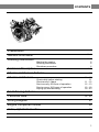
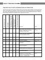
1
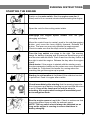
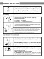
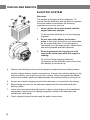
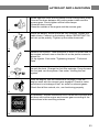
FOREWORD
Before you start running your new Volvo Penta marine engine, you would be
advised to read through this instruction book carefully. It contains all the
information you need to run and service your engine in the best possible way.
Volvo Penta has built up an extensive service organization with service shops and
specially trained personnel at your service.
Always contact your local Volvo Penta representative for advice and when in need
ot service and parts.
We are convinced that the demands on good running economy and top
performance, which you have every right to expect of a quality product, will be met
and that your engine will serve you faithfully on many pleasant cruises.
WARRANTY
A warranty certificate is supplied with each engine. It contains the warranty
conditions for the engine and should be studied carefully.
Also included is a report card which is to be completed by the dealer or boat
seller. If our warranty is to apply, however, it is an absolute condition that the
measures given in the “Check and Service Scheme” are carried out and that your
engine and equipment are looked after according to the instructions in this
manual. When in doubt, always get in touch with an authorized Volvo Penta
dealer.
In all correspondence with your dealer and when ordering parts, state the type
designation and serial number of the engine and reverse gear (see starboard side
of engine).
CONTENTS
2
Presentation
3-4
General Information
5-6
Running Instructions
Starting the engine
Running instructions
Shutdown procedure
Technical Description
Checks and Service Scheme
5
6
6
7-9
10
Fault Tracing Scheme
11 - 17
11
11 - 12
12 - 13
13 - 19
20 - 23
24
Technical Data
25 - 26
Checks and Service
Check daily before starting
Check every 14 days
Service every 50 hours of operation
Service every 100 hours of operation
Laying-up and launching
Wiring Diagram
27
Engine Component Guide
28
Index, alphabetical order
29
1
PRESENTATION
INSTRUMENT PANEL
1.
2.
3.
Switch, optional equipment
Warning lamp, “Excess temp.”
Place for instrument (ø 52 mm opt. equipment)
4.
5.
6.
7.
8.
Warning lamp, “No oil pressure”
Switch, optional equipment
Warning lamp, “No battery charging”
Siren, “No oil pressure, excess temp.”
Key switch
Volvo Penta Single Control System
CONTROL SYSTEM
For side mounting
1.
2.
Control lever
Disengaging button
Push in the button when the control lever is in neutral
and move the lever a bit forwards. Release button.
The lever is now used only for engine speed control.
To use the lever for both engine speed control and
gear-changing, push in the button and pull back the
lever to neutral.
N
=
Neutral
F = Control lever in position for running “Forward”
R = Control lever in position for running “Reverse”
T = Engine speed control
2
GENERAL INFORMATION
Important information on the function of your engine:
FUEL
Use diesel fuel oil of quality “Autodiesel”. Poorer fuel quality
can cause interruptions in operation.
LUBRICATING
OIL
Use only oil with quality CD (DS) according to the API system.
Volvo Penta oil for diesel engines can be used with
advantage since it meets these quality demands. See under
“Technical Data” concerning the viscosity.
RUNNING-IN
A new marine engine must be run-in with due care during the
first 20 hours of operation. If full output is taken out during this
time, it should only be done for short periods.
Oil change. Change the engine lubricating oil and the oil filter
after the engine has been run for 20 hours. See further under
“Checks and Service”.
ENGINE SPEED
Max. speed: 41.7 rev/sec (2500 rev/mm).
For choice of correct propeller, refer to the Volvo Penta propeller diagram. Check the
engine speed with normal load in the boat. In order to utilize the maximum performance
of the engine, an engine speed as high as possible should be chosen but not, however,
greater than 41.7 rev/sec (2500 rev/mm).
NOTE. When the boat has been in the water for some time, the speed and max. rev/mm
can drop due to marine growth on the hull. Prevent marine growth by painting the bottom
of the boat with anti-fouling paint. See under “Measures taken when launching”.
3
GENERAL INFORMATION
SAFETY EQUIPMENT
Irrespective of whether the boat is being used for long cruises or short bathing trips, the
boat should be equipped with the safety equipment listed below. It can, of course, be
supplemented further according to personal tastes. Investigate at regular intervals to
ensure that there is safety equipment on board and that it is in working order.
LIFE-JACKETS for all on board.
FIRE EXTINGUISHER, approved, at least one and installed where it is easy to get at.
DISTRESS ROCKETS and matches. Packed watertight.
FIRST-AID BOX
TOOLS suitable for the equipment on board.
ON BOARD KIT containing, e.g. impeller, etc.
ANCHOR with line.
RADAR REFLECTOR
RADIO for listening to, e.g., weather reports.
COMPASS which is deviated.
BOAT HOOK and paddle.
MOORING ROPES
FOG-HORN and whistle.
FLOATING ANCHOR
TORCH
PREPARATIONS BEFORE STARTING
Make sure that:
There is no FUEL LEAKAGE
There is no WATER LEAKAGE from engine and hull
There is no OIL LEAKAGE
There is no SMELL OF LP-GAS in the deep cavities in the boat or elsewhere
The OIL LEVEL is correct
There is enough FUEL for the planned voyage
The proper NAUTICAL CHARTS are on board for the planned voyage
If there are some other persons on board, make sure that some of them is able to
operate the boat.
If there are persons on board who have never been on a boat before, tell them where the
life-jackets are located and where the fire-extinguisher is placed. Also tell them anything
more you think necessary from a safety point of view. Should something unexpected
happen during the voyage, it is very often too late to tell those on board how safety
equipment works.
4
RUNNING INSTRUCTIONS
STARTING THE ENGINE
Switch on the main switch. Start the engine room fan (if
fitted) and let it run several minutes before starting the engine.
Open the cock for the cooling water intake.
Disengage the engine speed control from the gearchanging as follows:
Move the control lever to neutral, push in the red disengaging
button, and move the lever slightly forwards. Release the
button. The lever can now only operate the engine speed.
Check to make sure that the stop control is pushed in.
Turn the key switch one stage to the right. The warning
lamps for battery charging and oil pressure should now go on
and the siren should sound. Push in and turn the key further to
the right to start the engine. Release the key when the engine
starts.
Hand starter. If the engine is started with the starting crank,
the decompression handle on the rocker arm cover should first
be folded up. Fold down this handle for running when the
cranking has got the engine up in speed.
Starting in cold weather is facilitated if the cold-start control
is pulled out. Push it in again after a while.
Check immediately after starting that the warning lamps for
the oil pressure and battery charging are out and that the siren
is quiet. If any of the lamps are on and the siren is
sounding, the engine must be stopped immediately and
an investigation made.
Run the engine warm at rapid idle. Check to make sure that
the cooling water flows out with the exhaust gases.
NOTE. The key switch should always be switched on as
long as the engine is running to ensure that there is
battery charging.
5
RUNNING INSTRUCTIONS
Reduce to idle and check that the engine is running smoothly.
Engage the control lever for gear-changing as follows:
Push in the red disengaging button and pull the lever back to
neutral. Release the button. The control lever can now be
used both for gear-changing and engine speed.
RUNNING
The single lever control has both engine speed and
manoeuvering functions.
F = Forward
R = Reverse
N = Neutral
T = Engine speed control
To achieve good running economy, the engine should not be
run at max. speed for a longer period.
Make sure that the battery charging warning lamp does not
light when the engine is running The siren will sound and the
respective warning lamp go on if the engine temperature
becomes excessive or the oil pressure too low.
SHUTDOWN PROCEDURE
After shutdown the engine should be allowed to idle for a
couple of minutes or so with the control lever in neutral.
Stop the engine by pulling out the stop control when the
engine is idling. Then turn back the key switch to the initial
position.
Switch off the main switch. NOTE. This switch must never
be switched off until the engine has stopped.
Close the fuel and cooling water cocks if the boat is not going
to be used for some time.
Check for leakage before leaving the beat.
In cold weather and whenever there is risk of icing, the
cooling water should he drained from the engine and reverse
gear. See under “Laying-up and launching”.
6
TECHNICAL DESCRIPTION
The MD5A is a single-cylinder, 4-stroke, marine diesel engine with direct injection and
sea-water cooling.
ENGINE ASSEMBLY
The engine block and cylinder head are made of cast iron. Cylinder angle 45o. The
cylinder liner is replaceable. The engine has overhead valves.
LUBRICATING SYSTEM
The lubricating system includes a full-flow oil filter which filters all the oil before it reaches
the lubricating points. A relief valve in the oil pump prevents the oil pressure from
becoming excessive.
ELECTRICAL SYSTEM
The engine has a starter motor and alternator with built-in rectifier. Voltage regulation is
taken care of by a transistorized regulator mounted on the alternator. The alternator
makes it possible to charge two battery circuits independent of each other if a charging
distributor (accessory) is fitted on the alternator.
A main fuse, which can easily be re-connected, is fixed to the engine. It protects the
electrical system from damage in the event of overloading. The wiring diagrams for the
engine and instrument panel are shown on page 27.
7
TECHNICAL DESCRIPTION
FUEL SYSTEM
The fuel system contains a feed pump with pre-filter, fine filter, injection pump and
injector. The feed pump, which is of the diaphragm type, has also a hand priming lever.
Also fitted is a cold-start device with lever for connection of the push-pull control.
COOLING S YSTEM
The engine is sea-water cooled. The cooling system includes a sea-water pump as well
as a water distributor housing with thermostat.
The sea-water pump has an impeller of neoprene rubber driven by the camshaft via a
rubber flange.
The thermostat installed in the water distributor housing regulates the water flow so that
the water always flows through the exhaust manifold and out into the exhaust elbow
irrespective of whether the engine is cold or warm.
8
TECHNICAL DESCRIPTION
REVERSE GEAR
The Volvo Penta reverse gear, type Mono Shift (MSB) has a reduction ratio of 1.91:1.
The reduction gear is integrally built with the reverse gear. Power transmission from the
engine to the reverse gear is via a rubber flange.
The Volvo Penta patented cone clutch is used for “Forward” and “Reverse” operation and
ensures smooth and quiet engagement. Very small forces are required to operate the
reverse gear.
9
CHECKS AND SERVICE SCHEME
Checks and service should be regularly carried out according to the intervals given
below. Let an authorized Volvo Penta Service Shop look after your engine.
CHECK DAILY BEFORE STARTING that
The oil level in the engine is between the marks on the dipstick
Page
11
CHECK every 14 days that
The oil level in the reverse gear is between the marks on the dipstick
The electrolyte level in the battery is correct
The belt tension
11
12
SERVICE EVERY 50 HOURS OF OPERATION:
Change the oil in the engine
Change the oil in the reverse gear
Check and adjust the valve clearances
12
13
13
SERVICE EVERY 100 HOURS OF OPERATIONS OR AT
LEAST ONCE EACH SEASON:
Change the oil filter
Check the pulley belt
Check-tighten the cylinder head bolts
Check the cooling system
Check the electrical system (fuses, etc.)
Fuel system, filter, strainer, injector, venting
13
14
15
15
16
17-19
SERVICE IN CONJUNCTION WITH LAYING-UP AND
LAUNCHING THE BOAT
Inhibiting scheme I. Inhibiting measures carried out with boat in the water.
Inhibiting scheme II. Inhibiting measures carried out with boat on land.
Service in connection with launching.
10
20
21
22
CHECKS AND SERVICE
CHECK DAILY BEFORE STARTING
OIL LEVEL IN ENGINE
Each day before starting check that the
oil level is between the marks on the
dipstick. Top up with oil if necessary
through the oil filler hole.
NOTE. Do not top up above the MAX.
mark. Concerning choice of oil, see
under “Technical Data”.
CHECKS every 14 days
OIL LEVEL IN REVERSE GEAR
Screw up the dipstick, wipe it clean and
insert it again without screwing it down.
Pull up the dipstick and check the oil
level which should be between the
marks. If necessary top up with oil
through the oil filler hole on the opposite
side of the reverse gear. Do not top up
above the MAX. mark.
Screw down the dipstick again. Note that
there is a sealing washer on the dipstick.
Concerning choice of oil, see under
“Technical Data”.
11
CHECKS AND SERVICE
ELECTROLYTE LEVEL IN BATTERY
The level should be between 5—10mm (3/16 – 3/8”) above the cell plates in the
battery. If necessary top up with distilled water. IMPORTANT. Observe great care
when doing this since the electrolyte is abrasive and the gas which is formed is
explosive.
BELT TENSIONING
Correct belt tension is necessary for full
alternator output. The belt should be so
tensioned that it can be depressed 5 mm
(3/16”) with the thumb midway between
the pulleys.
To tension the belt, first slacken the
alternator retaining points, stretch the
belts and tighten up the points again.
A well worn or crached belt should be
replaced.
SERVICE EVERY 50 HOURS OF OPERATION:
CHANGE OIL IN ENGINE
With a new or newly reconditioned
engine, the oil should be changed for the
first time after 20 hours of operation and
after that after every 50 hours of
operation.
Run the engine warm. Suck up the oil
through the dipstick hole.
Fill with oil to the correct revel. See
under “Technical Data” concerning
choice of oil.
NOTE! Change also the oil filter (Fram
Filter PH3614) at every other oil change.
12
CHECKS AND SERVICE
CHANGE OIL IN REVERSE GEAR
The oil can be drained from the reverse
gear by removing the plug under it or by
sucking up the oil through the dipstick
hole with the help of an oil scavenging
pump.
Fill with oil through the filler hole to the
correct level on the dipstick. NOTE. Do
not fill above the ‘MAX. mark on the
dipstick. Concerning choice of oil, see
under “Technical Data”
VALVE CLEARANCE
The valve clearance should be checked
and adjusted by authorized personal.
See under “Valves”, in “Technical Data”.
SERVICE EVERY 100 HOURS OF OPERATION OR AT LEAST
ONCE EACH SEASON
OIL FILTER
The oil filter should be replaced for the first time after 20 hours of operation during the
running in period and subsequently at every other oil change. IMPORTANT. Before
removing the filter, switch off the main switch. Screw off and scrap the oil filter. It may
be necessary in certain cases to lift off the belt and tension out the alternator to permit
free passage for the filter.
13
CHECKS AND SERVICE
Coat the new filter rubber gasket with oil.
Check the area on the engine in contact
with the filter and screw on the filter by
hand until it just touches the engine. Then
screw the filter a further half turn, but not
more.
NOTE. Only use a genuine oil filter.
Start the engine, allow it to idle and
immediately check that the oil pressure
warning lamp is out.
Check the oil level and also for any
leakage round the oil filter.
CHECK THE BELT
Check the belt thoroughly for wear and
cracks. Replace it if there is any indication of such. To remove the belt, slacken
the alternator retaining points in order to
be able to slip the belt off. Wipe clean the
belt groove on the pulleys before fitting
the new belt. Tension the belt so that it
can only be depressed 5 mm (3/16”) with
the thumb between the pulleys. After the
engine has been run for an hour or so,
re-check and if necessary adjust the belt
tensioning.
14
CHECKS AND SERVICE
CHECK-TIGHTEN THE CYLINDER HEAD BOLTS
Authorized personal should check-tighten
the bolts with a torque wrench before
starting a new or newly reconditioned
engine for the first time and again after it
has been in operation for 20 hours.
Check the valve clearance after tightening
up the bolts. The bolt-tightening sequence
can be seen from the adjacent illustration.
Concerning the tightening torque, see
under “Technical Data”.
CHECK THE COOLING SYSTEM
The cooling system is functioning normally when the “Temp” lamp is out and the siren is
quiet. Excessive temperature (“Temp” goes on, the siren sounds) may be due to the
following: clogged water intake, defective impeller or flange in the sea-water pump,
faulty thermostat or temp. gauge sender. Look out for water penetration during all
work on the cooling system.
Check and replace the impeller
The impeller can be damaged due to,
e.g., shortage of water. Remove the cover
on the water pump. Pull out the shaft the
length required in order to screw out the
impeller lock bolt. Hold against the shaft
and pull off the impeller. If the impeller is
damaged, fit a new one. NOTE! If the
shaft has been removed entirely from the
pump housing, check when re-fitting it
that the D-ring between the sealing rings
in the housing gets onto the shaft.
Tighten up the impeller with the lock bolt.
If the impeller and shaft can be rotated
then the flange is defective. A new flange
can be fitted after the pump has been
removed. Fit the cover with its gasket.
15
CHECKS AND SERVICE
ELECTRIC SYSTEM
Alternator
The engine is equipped with an alternator. To
ensure that the alternator with the built-on regulator
functions without interruptions the following
important points must be observed:
1.
Never switch off the main switch until the
engine has been stopped.
To do otherwise would be to ruin the charging
regulator.
2.
Do not mix up the battery connection
poles. A plus sign and a minus sign are marked
on the respective poles. The minus pole is
connected up to the engine body. Cable shoes
should be greased and wall tightened.
3.
Re-wiring between the charging circuits
may not be carried out while the engine is
running.
Fit a Volvo Penta charging distributor
(accessory) on the alternator when more than
one battery is connected up.
4.
Observe the following in the event the engine is started with an auxiliary battery:
Let the ordinary battery remain connected up. Connect the auxiliary battery to the
ordinary battery, plus to plus and minus to minus. When the engine has started,
remove the auxiliary battery but do not break the ordinary battery’s wiring circuit.
5.
Do not use a rapid charging unit when the alternator is connected to the battery.
6.
Before doing any work on the alternator equipment first disconnect both the
battery cables.
7.
In the event any electrical welding work is done on the engine or the installation
components, disconnect the charging regulator cables at the alternator and
insulate the cable ends.
8.
Check regularly the belt tension and the cable connections.
16
CHECKS AND SERVICE
Change Fuse
A fusebox is mounted on the cylinder. A fuse breaks the electrical system when the
system is overloaded. Re-connect the electrical system by transferring the cable
connection to the next fuse contact.
Starter motor and alternator
All work connected with the starter motor and alternator shoold be done by an authorized
service shop. Inspection and control should he carried out in connection with a general
inspection of the engine.
BATTERY
Checking the state of charge of the battery
The state of charge of the battery should he checked at cast once each season. This is
done by using a hydrometer which shows the specific gravity of the electrolyte, this
varying with the state of charge. (See the Technical Data.)
FUEL SYSTEM
Observe the greatest cleanliness when handling the fuel system.
IMPORTANT: Try to avoid fuel splash.
Change fuel filter
The filter element in the fuel filter should
be changed at least once each season.
To do this remove the filter centre screw
and lift off the filter. Clean the container
and contact surfaces. Fit the new filter
element and its gasket. Pump up the fuel
with the hand primer. Vent the fuel system.
If the pumping effect is poor, turn over the
engine a bit so that the drive cam alters its
position.
17
CHECKS AND SERVICE
Extra fuel filter
If an extra fuel filter is fitted together with a
water separator, check the transparent
bowl to see if there is any water in the fuel.
If necessary, drain the filter via the cock in
the bottom of the bowl.
Try to avoid fuel splash. Pump up the fuel
with the hand primer and vent the system.
The fuel filter element should be changed
at least once a season.
FUEL STRAINER
The fuel pump on the engine has a built-in
strainer which is accessible after removing
the cover. Clean the strainer at least once
a season.
Immediately after starting the engine,
check for leakage.
Always vent the fuel system. See under
“Venting the fuel system”.
Injector
The injector should be removed once a season and handed in to a diesel shop for
cleaning and checking the opening pressure, the spray pattern and for leakage. To
remove the injector, unscrew the delivery pipe and the by-pass oil line. Fit protective caps
over the openings.
Release both the nuts over the fork holding the injector to the cylinder head and lift up the
injector. If the injector feels stiff to remove due to gumming, grip it with, e.g., polygrip
pliers and carefully rotate it back and forth while levering it up at the same time (with a
screwdriver, e.g., under the fork(. Before fitting, check to make sure the contact surface
on the injector and copper sleeve is clean. Connect up the delivery pipe and the return
line but do not tighten the delivery pipe nut at the injector. Turn over the engine with the
starter motor until fuel comes from the delivery pipe. Tighten up the delivery pipe nut and
make sure the delivery pipe cone is fitted properly. Concerning tightening torque, see
“Technical Data”.
18
CHECKS AND SERVICE
Venting the fuel system
In order for the engine to be able to start, the fuel system must be vented on the following
occasions:
When changing the fine filter.
When draining through the drain hole.
When cleaning the fuel pump strainer.
After running the fuel tank empty.
When installing the fuel injection pump.
With leakage and work on the fuel lines.
When the engine has not been used for a
long time.
Venting is as follows:
1.
Open the vent screw on the fuel filter.
2.
Pump forward the fuel with the help of the hand primer until fuel free from air bubbles
flows out. Close the vent screw. If the pumping effect is poor, turn over the engine a
bit so that the pump drive cam alters its position.
3.
If the fuel injection pump has been removed, or when starting an entirely new engine
for the first time, the fuel injection pump must be vent. To do this open the vent
screw on the pump. Pump with the hand primer until fuel free from air comes out.
Slacken the injector delivery pipe nut and turn over the engine by means of the
starter motor until fuel comes from the delivery pipe. Tighten up the delivery pipe nut
and start the engine.
1.
2.
3.
4.
Vent screw, fuel filter
Hand primer
Vent screw, injection pump
Delivery pipe nut
19
LAYING-UP AND LAUNCHING
SERVICE IN CONNECTION WITH LAYING-UP AND
LAUNCHING THE BOAT
INHIBITING ENGINE AND REVERSE GEAR
IDLE ENGINE FOR BRIEF PERIODS WITH BOAT IN THE WATER
To prevent the engine from corrosion attacks, it must be run warm at least once every
14 days as long as the boat is in the water. If it is anticipated that the boat will not be
used for more than a month, long-term inhibiting should be carried out.
INHIBITING FOR A LONG PERIOD
An authorized service shop should test the engine and equipment before inhibiting the
engine for a long period acc. To Inhibiting Schemes I and II. A suitable procedure would
be to test the compression.
SERVICE INSTRUCTION
Inhibiting Scheme I
Carried out with the boat in the water
Run the engine warm.
1
Pump out all the oil from the engine and reverse gear.
Use an oil scavenging pump.
2
Change the oil filter. Fill the engine and reverse gear to the correct
level with Volvo Penta oil, which also has rustproofing properties,
to the correct level. The lubricating system is thereafter ready for
operation the next season.
If rustproofing oil is used, it should be of the type Esso Rustban
623, Sheel Ensis Oil or corresponding.
In this case, the oil filter should be replaced when launching.
3
20
LAYING-UP AND LAUNCHING
Drain the fuel filter.
4
Disconnect the fuel pump flexible suction hose from the fuel
system and insert the free end in a can filled with 1/3rd Volvo
Penta oil or preservative oil and 2/3rds diesel fuel oil. Bleed the
fuel system. Let the engine run at rapid idle for about 10
minutes.
NOTE! If the fuel system has an electrically operated fuel pump,
it must be switched off before the engine is started.
5
Inhibiting Scheme II
Carried out with the boat on land
Drain the cooling water from the engine and reverse gear.
Check to make sure that the water runs out since impurities can
block the cock. Then close all cocks and re-fit the drain cock in
the reverse gear.
6
7
Disconnect the reverse gear suction line from the reverse gear.
Connect a hose with inner diameter 1/2” and, insert the free
hose end in a container with fresh water. Arrange to have water
added to the container and run the engine at idle for about 5 –
10 minutes so that it is flushed throughout with fresh water.
Make sure that there is no dirt near the exhaust outlet. Drain all
water from the engine and reverse gear. Then close all drain
points.
Mix a rustproofing mixture consisting of 15 - 20 litres
(13 Imp.qts. = 16 us qts. - 18 lmp.qts. = 21 US qts.)
fresh water and 2 - 4 litres (1.8 Imp.qts. = 2.0 US qts. - 3.5
lmp.qts. = 5.3 US qts.) rustproofing oil.
NOTE! Water first and then the oil.
Use, e.g., Esso Cutwull 40, Shell Donax C or similar. As an
alternative, a freeze-resistant 30 % glycol mixture can be used.
8
21
LAYING-UP AND LAUNCHING
Insert the hose into the rustproofing mixture. Start the engine
and allow it to idle until the mixture is finished. NOTE! The
water pump must never be allowed to run dry.
9
Since the rustproofing mixture does not provide any protection
against freezing, it must be drained from the engine and
reverse gear. Remove the cover from the cooling water pump.
Check to make sure the impeller is in good condition.
NOTE! Do not pull out the impeller if it is in good condition.
10
Remove the injector and hand it in to a diesel shop for cleaning
and checking. Inject Volvo Penta oil into the cylinder. Turn over
the engine several turns with the starter motor or the crank.
NOTE! Prevent oil splash. Fit the checked injector but do not
final-tighten it. It will be removed again before launching.
11
Clean the outside of the engine and reverse gear. Touch up any
bare patches on the paintwork with the same type of paint as
the original. Spray the electrical system components and all the
controls with anti-moisture spray.
12
Remove the battery. It needs to be maintained to prevent it from
being damaged.
13
Service in connection with launching
If Volvo Penta oil has been used, only the oil level in the engine
and reverse gear needs to be checked. If another type of
preservative oil has been used, both oil and filter must be
replaced. See under “Service 14 after every 50 hours of
operation”.
14
22
LAYING-UP AND LAUNCHING
Screw tight the cover with its gasket on the cooling water pump.
Connect the hose between the cooling water intake and the
reverse gear. Check-tighten all the hose clamps.
Close the drain cocks.
Clean the outside of the engine and the reverse gear.
15
Install the battery, which should be fully charged. Grease the
cable shoes. Connect up the battery cables. IMPORTANT! Do
not mix up the polarity. Tighten up the cable shoes well.
16
Remove the injector. Take measures to avoid oil splash and run
the engine several turns so that the oil on the piston crowns is
blown out.
Fit the injector. See under “Tightening torques”, “Technical
Data”.
17
Launch the boat. Change the fuel-filter cartridge. Pump forward
the fuel and vent the system. See under “Venting the fuel
system”.
18
Start the engine. See the instructions on page 5. Run the
engine warm with the reverse gear engaged. Check to make
sure there is no leakage of fuel, air, water or exhaust gases .
Check that all the controls, etc., are functioning properly.
19
If necessary, contact authorized Volvo Penta service shops and
let them service the engine and reverse gear according to the
instructions in the servicing scheme.
20
23
FAULT TRACING SCHEME
TRACING FAULTS WITH INTERRUPTIONS IN OPERATION
Engine becomes abnormally hot
Engine runs unevenly or
vibrates abnormally
Engine does not reach correct
operating speed at full throttle
Engine stops
Engine does not start
The fault tracing scheme given below lists only the most usual reasons for faults that give
rise to interruptions in operation. With the help of the instructions given in this handbook,
the owner can generally remedy most of the reasons for the faults listed below. When in
doubt always contact the nearest Volvo Penta service shop.
Reason
See
Main switch not switched on; flat
battery, breakage in electric
cables or blown fuse.
pp 5, 12, 16,
17, 27
Empty fuel tank, closed fuel
cock, blocked fuel filter
pp 17, 18
X
Water, air or impurities in fuel
pp 17, 18, 19
X
Defective injector
pp 18, 26
Idling speed not properly
adjusted
p 25
X
X
X
X
X
X
X
X
X
X
X
Boat overloaded
X
Marine growth on boat bottom
Damaged propellor
X
X
24
Blockage in cooling water
intake, cooling jackets, defective
impeller, or thermostat
p 15
TECHNICAL DATA
Technical Data
General
Engine designation
MD5A
4-stroke diesel with direct
injection
Operation
Number of cylinders
Propeller shaft output kW (h.p.) at 2500 rev/min
(acc. To DIN Leistung B f ür Dauberbetrieb)
1
5.5 (7.5)
Max operating speed rev/min
2500
Bore, mm (in)
84 (3.307)
Stroke, mm (in)
80 (3.150)
3
3
Displacement, dm (in )
0.443 (27)
2
2
Compr. pressure, MPa (kp/cm = lbf/in )
200 - 220
(starter motor speed)
(20 - 22 = 284 - 313)
Idling speed, rev/min approx
700
Direction of rotation looking at flywheel
Clockwise
Engine inclination underway:
Rearwards, max.
15°
To the sides, max.
Engine weight, incl. Reverse gear, kg (lb)
20°
111 (244)
Valves
Valve clearance, hot engine
Inlet, mm (in)
0.30 (0.0012)
Exhaust, mm (im)
0.35 (0.0014)
Reverse Gear
Type designation
MSB
Reduction ratio “Forward” and “Reverse”
1.91:1
Lubricating System
Engine
Oil Capacity, engine, litres (Imp.qts. = US qts.) ex cl. filter
Incl. filter
Oil quality
2.0 (1.80 = 2.10)
2.1 (1.85 = 2.20)
Diesel lubricating oil
Service CD (DS)
Viscosity:
Above +10°C (14°F) - Volvo Penta CD Double Grade oil
SAE 20W/30
Below +10°C (14°F) - Volvo Penta CD Single Grade oil
SAE 10W
Oil pressure, hot engine
2
2
15 - 25 (1.5-2.5 = 21-35)
2
2
40 - 50 (4.0-5.0 = 57-71)
Idling speed, MPa (kp/cm = lbf/in )
At full speed, MPa (kp/cm = lbf/in )
25
TECHNICAL DATA
Reverse Gear
Oil quality/Viscosity
See under “Engine”
Oil capacity, litre (qt.)
0.55 (0.5)
Cooling System
Thermostat, starts to open at °C (°F)
60°±2 (140±2)
fully open at °C (°F)
90° (195)
Fuel System
Fuel injection pump, make & type
2
Bosch PFR1K
2
Feed pressure, MPa (kp/cm = lbf/in )
7.5 (0.75 = 11)
Injector, make Bosch, holder
KBAL 65
nozzle
DLLA 150
2
2
opening pressure, MPa (kp/cm = lbf/in )
1800 (180 = 2560)
Pre-injection angle, crankshaft degrees B.T.D.C.
25 - 28°
Fuel quality “Autodiesel”
Cet. rating minimum 45
Electrical System
Battery voltage
12v
Battery capacity, standard
60 Ah
max
120 Ah
Starter motor
0.8 kW (1.1 h.p.)
Alternator
35A (420W)
Battery, electrolyte specific gravity:
Charging carried out at g/cm
Fully charged battery, g/cm
3
3
1.230
1.275 - 1.285
Tightening Torques
Cylinder head nuts, Nm (kpm = lb.ftf)
70 (7.0 = 50)
Connecting rod bolts, Nm (kpm = lb.ftf)
70 (7.0 = 50)
Crankshaft main bearings, Nm (kpm = lb.ftf)
70 (7.0 = 50)
Flywheel nut, Nm (kpm = lb.ftf)
500 (50.0 = 362)
Injector nuts, Nm (kpm = lb.ftf)
10 (1.0 = 7)
26
WIRING DIAGRAM
Cable Colour Code
Marking
A
B
B’
B”
C
C’
C”
F
G
H’
I
I’
J
J’
J”
K
L
M
Colour
White
Black
Black
Black
Red
Red
Red
Yellow
Brown
Blue
Green/Red
Green/Red
Green
Green
Green
Blue/Yellow
White/Red
Blue/Red
2
mm
6
1.5
0.6
0.75
6
35
0.6
1.5
1.5
35
1.5
0.75
1.5
0.6
0.75
0.75
0.75
0.75
A.W.G.
9
15
19
18
9
1
19
15
15
1
15
18
15
19
18
18
18
18
List of Components
9.
Place for instruments, opt. equipment)
1.
Extra switch
10.
Rapid connector
2.
Battery charging warning lamp
11.
Starter mot or
3.
Excessive temp. warning lamp
12.
Alternator
4.
Low oil pressure warning lamp
13.
Fusebox
5.
Key switch
14.
Main switch
6.
Siren
15.
Battery
7.
Alarm unit
16.
Temperature sender
Battery charging warning lamp (for battery circuit,
opt. equipment)
17.
Oil pressure sender
8.
27
ENGINE COMPONENT GUIDE
1.
Connection for manual
starting crank
2.
Fusebox
3.
Thermostat housing
4.
Decompression handle
5.
Injector
6.
Oil filler cap, engine
7.
Reverse gear water drainage
8.
Reverse gear oil drainage
9.
Engine water drainage
10. Reverse gear oil filler
11. Cooling water pump
12. Reverse gear oil dipstick
13. Fuel filter
14. Vent screw
15. Fuel hand primer
16. Engine oil dipstick
17. Oil filter
The tool kit supplied with the engine contains the following tools:
US-spanner 10-12, UP-spanner 14-16 , screwdriver, Phillips screwdriver, flat end pliers,
oil scavenging pump with hose and suction pipe as well as Allen spanners for the drive.
28
INDEX
Alternator
Battery
Belt tensioning
Charging regulator
Controls
Cooling system
Cylinder head bolts
7, 14, 16, 27
12
12, 14
7, 16
2, 6
8
15
De-inhibiting
Drain cocks
22
28
Electrical system
Engine assembly
16
7
Fault tracing scheme
Fuel
Fuel filters
Fuel pump
Fusebox
Hand primer
Hand starter
Impeller
Inhibiting
Injector
Instruments
24
3
17
8
7, 17
8, 17, 23, 28
5, 28
15
20
18, 23
2, 27
Lubricating oil
Main Switch
Oil change
Oil dipstick, engine
Oil dipstick, reverse gear
Oil filter
Oil level check
3, 25
5, 6
12, 13
28
28
14, 20, 28
11
Preparations before starting
4
Running
6
Safety equipment
Sea-water pump
Starter motor
Starting
4
8, 15, 28
17
5
Technical data
Thermostat
25, 26
8, 26
Valve clearances
Venting the fuel system
13, 25
19
Wiring diagrams
27
29