1
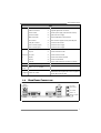
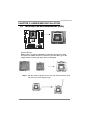
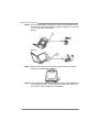
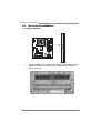
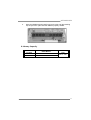
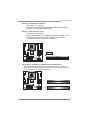
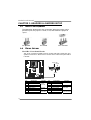
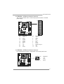
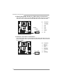
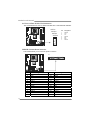
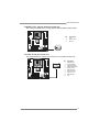
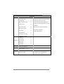
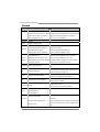
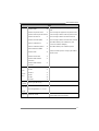
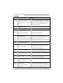
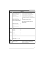
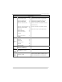
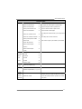
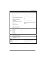
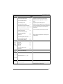
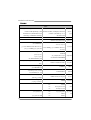
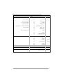
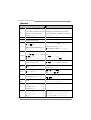
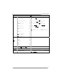
GF7100P-M7S Setup Manual FCC Information and Copyright This equipment has been tes ted and found to comply with the limits of a Class B digital devic e, purs uant to Part 15 of the FCC Rules . T hese limits are designed to provide reasonable protec tion against harmful interference in a residential installation. T his equipment generates , uses , and c an radiate radio frequency energy and, if not ins talled and used in accordance with the instructions , may cause harmful interference to radio communications . There is no guarantee that interference will not occur in a particular ins tallation. The vendor makes no representations or warranties with respec t to the contents here and s pecially disclaims any implied warranties of merchantability or fitness for any purpose. Further the vendor reserves the right to revise this publication and to make c hanges to the c ontents here without obligation to notify any party beforehand. D uplication of this publication, in part or in whole, is not allowed without first obtaining the vendor’s approval in writing. The content of this user’s manual is subject to be c hanged without notice and we will not be res ponsible for any mis takes found in this user’s manual. All the brand and produc t names are trademarks of their respec tive companies . Table of Contents Chapter 1: Introduction.....................................................3 1.1 Before You Start................................................................... 3 1.2 Package Checklist................................................................ 3 1.3 Motherboard Features.......................................................... 4 1.4 Rear Panel Connectors.......................................................... 5 1.5 Motherboard Layout ............................................................ 6 Chapter 2: Hardware Installation........................................7 2.1 Installing Central Processing Unit (CPU) ................................ 7 2.2 FAN Headers........................................................................ 9 2.3 Installing System Memory.....................................................10 2.4 Connectors and Slots ............................................................12 Chapter 3: Headers & Jumpers Setup................................. 14 3.1 How to Setup Jumpers..........................................................14 3.2 Detail Settings.....................................................................14 Chapter 4: RAID Functions ............................................... 21 4.1 Operation System................................................................21 4.2 Raid Arrays.........................................................................21 4.3 How RAID Works.................................................................21 Chapter 5: Useful Help ..................................................... 25 5.1 Driver Installation Note .......................................................25 5.2 Award BIOS Beep Code........................................................26 5.3 Extra Information................................................................26 5.4 Troubleshooting...................................................................27 A ppendencies: SPEC In Other Language............................. 28 German................................................................................................28 France..................................................................................................30 Italian..................................................................................................32 Spanish ................................................................................................34 Portuguese...........................................................................................36 Polish...................................................................................................38 Russian ................................................................................................40 Arabic..................................................................................................42 Japanese ..............................................................................................44 GF7100P-M7S CHAPTER 1: INTRODUCTION 1.1 BEFORE YOU ST ART Thank you for choosing our product. Be fore you start installing the mothe rboard, please make sure you follow the instructions be low: Prepare a dry and stable work ing environment with sufficie nt lighting. Always disconne ct the compute r from powe r outle t be fore ope ration. Before you take the mothe rboard out from anti-static bag, ground yourse lf prope rly by touching any safe ly grounde d appliance, or use grounded wrist strap to remove the static charge. Avoid touching the compone nts on mothe rboard or the rear side of the board unless ne cessary. Hold the board on the edge , do not try to be nd or flex the board. 1.2 Do not leave any unfastene d small parts inside the case afte r installation. Loose parts will cause short circuits which may damage the equipment. Keep the compute r from dange rous a rea, such as hea t source , humid air and wate r. PACKAGE CHECKLIST HDD Cable X 1 Se rial ATA Cable X 1 Rear I/O Panel for ATX Case X 1 Use r’s Manual X 1 Fully Se tup Drive r C D X 1 FDD Cable X 1 (optional) Se rial ATA Powe r Cable X 1 (optional) USB 2.0 Cable X1 (optional) S/PDIF out Cable X 1 (optional) Note: The package contents may differ by area or your motherboard version. 3 Motherboard Manual 1.3 MOT HERBOARD FEAT URES SPEC CPU LGA 775 Supports Hyper-Threading / Execute Disable Bit / Intel Core2Duo / Core2Quad / Celeron Enhanced Intel SpeedStep® / Intel Architecture-64 / 4xx / Pentium D / Pentium 4 processor Extended Memory 64 Technology / Virtualization Supports 45nm CPU Technology FSB Support 1333 MHz Chipset GeForce 7100/nForce 630i ITE 8718F Super I/O Environment Control initiatives, Provides the most commonly used legacy H/W Monitor Super I/O functionality. Fan Speed Controller Low Pin Count Interface ITE's "Smart Guardian" function DDR2 DIMM Slots x 2 Single Channel Mode DDR2 memory module Main Max Memory Capacity 4GB Memory Each DIMM supports 512MB/1GB/2GB DDR2 Graphics GeForce 7100/nForce 630i IDE Integrated IDE Controller SATA II Integrated Serial ATA Controller LAN Realtek 8111B / 8111C(optional) Sound ALC662 Registered DIMM and ECC DIMM is not supported Max Shared Video Memory is 512MB (under OS) Ultra DMA 33 / 66 / 100 / 133 Bus Master Mode supports PIO Mode 0~4, Data transfer rates up to 3 Gb/s. SATA Version 2.0 specification compliant. 10 / 100 Mb/s and 1Gb/s Auto-Negotiation Half / Full duplex capability 5.1 channels audio out High Definition Audio PCI slot x2 Supports PCI expansion cards PCI Express x16 slot x1 Supports PCI-E x16 expansion cards PCI Express x 1 slot x1 Supports PCI-E x1 expansion cards On Board Floppy connector x1 Each connector supports 2 Floppy drives Connector Printer Port connector x1 Each connector supports 1 Printer port IDE Connector x1 Each connector supports 2 IDE device SATA Connector x4 Each connector supports 1 SATA devices Front Panel Connector x1 Supports front panel facilities Front Audio Connector x1 Supports front panel audio function Slots 4 Supports DDR2 533 / 667 / 800 GF7100P-M7S SPEC CD-in Connector x1 Supports CD audio-in function S/PDIF out connector x1 Supports digital audio out function CPU Fan header x1 CPU Fan power supply (with Smart Fan function) System Fan header x2 System Fan Power supply CMOS clear header x1 Restore CMOS data to factory default USB connector x3 Each connector supports 2 front panel USB ports Serial port Connector x1 Connects to RS-232 Port Power Connector (24pin) x1 Connects to Power supply Power Connector (4pin) x1 Connects to Power supply PS/2 Keyboard x1 Connects to PS/2 Keyboard VGA port x1 Connect to D-SUB monitor Back Panel DVI-D port x1 Connect to DVI-D monitor I/O LAN port x1 Connect to RJ-45 ethernet cable USB Port x4 Connect to USB devices Audio Jack x3 Provide Audio-In/Out and microphone connection Board Size 244 mm(W) x 244 mm(L) Special Features RAID 0 / 1 / 5 / 0+1 support OS Support Windows XP / VISTA 1.4 Biostar Reserves the right to add or remove support for any OS With or without notice. REAR PANEL CONNECT ORS LAN PS/2 Keyboard Line In/ Surround Line Out Mi c In 1/ Bass/ Center USBX2 DVI-D VGA USBX2 5 Motherboard Manual 1.5 MOT HERBOARD LAYOUT JUSBKB1 JCFAN1 LGA775 JDVI1 JUS BV1 CPU1 DIMMA2 JVGA1 DIMMA1 JATXPWR1 JNFAN1 GeForce 7100 nForce 630i IDE1 JUSBLAN1 BIOS AUDIO1 PE X1_1 LAN PE X16_1 BAT1 SATA2 PCI1 SATA4 Super I/O Codec PCI2 JAUDIOF1 JCDIN1 JSPDIF_OUT1 JPRNT1 SATA1 JUSB2 JUSB3 JUSB4 Not e: ■ represe nts the 1st pin. 6 JCOM1 SATA3 JSFAN1 JUSBV2 JCMOS1 JPANEL1 FDD1 JATXPWR2 GF7100P-M7S CHAPTER 2: HARDWARE INSTALLATION 2.1 INST ALLING CENT RAL PROCESSING UNIT (CPU) Special Notice: Remove Pin Cap before installation, and make good preservation for future use. When the CPU is removed, cover the Pin Cap on the empty socket to ensure pin legs won’t be damaged. Pin-Cap Step 1: Pull the socket locking lever out from the socket and then raise the lever up to a 90-degree angle. 7 Motherboard Manual Step 2: Look for the triangular cut edge on socket, and the golden dot on CPU should point forwards this triangular cut edge. The CPU will fit only in the correct orientation. Step 2-1: Step 2-2: Step 3: Hold the CPU down firmly, and then lower the lever to locked position to complete the installation. Step 4: Put the CPU Fan and heatsink assembly on the CPU and buckle it on the retention frame. Connect the CPU FAN power cable into the JCFAN1. This completes the installation. 8 GF7100P-M7S 2.2 FAN HEADERS These fan headers support cooling-fans built in the computer. The fan cable and connector may be different according to the fan manufacturer. Connect the fan cable to the connector while matching the black wire to pin#1. JCFAN1: CPU Fan Heade r 1 4 Pin Assignment Ground +12V FAN RPM rate sense Smart Fan Control (By Fan) 1 2 3 4 JNFAN1: North Bridge Fan Heade r JSFAN1: System Fan He ader J NFAN1 1 3 Pin 1 2 3 Assignment Ground +12V FAN RPM rate sense JSFAN1 1 3 Note: The JCFAN1 supports 4-pin head c onnector. The J SFAN1 and JNFAN1 s upport 3-pin head connectors. When connecting with wires onto connectors, pleas e note that the red wire is the positi ve and s hould be c onnected to pin#2, and the bl ac k wire is Ground and shoul d be connected to GND. 9 Motherboard Manual 2.3 INST ALLING SYST EM MEMORY DIM MA1 DIM MA2 A. Memory Modules 1. 10 Unlock a DIMM slot by pressing the retaining clips outward. Align a DIMM on the slot such that the notch on the DIMM matches the break on the Slot. GF7100P-M7S 2. Insert the DIMM vertically and firmly into the slot until the retaining chip snap back in place and the DIMM is properly seated. B. Memory Capacity DIMM Socket Location DIMMA1 512MB/1024MB/2048MB DIMMA2 512MB/1024MB/2048MB DDR2 Module Total Memory Size Max is 4GB. 11 Motherboard Manual 2.4 CONNECT ORS AND SLOT S FDD1: Floppy Disk Conne ctor The motherboard prov ides a standard floppy disk connector that supports 360K, 720K, 1.2M, 1.44M and 2.88M floppy disk ty pes. This connector supports the prov ided f loppy drive ribbon cable. 34 33 2 1 IDE1: Hard Disk Conne ctor The motherboard has a 32-bit Enhanced PCI IDE Controller that prov ides PIO Mode 0~4, Bus Master, and Ultra DMA 33/66/100/133 f unctionality. The IDE connector can connect a master and a slave drive, so y ou can connect up to two IDE devices. 12 40 39 2 1 GF7100P-M7S PEX16_1: PCI-Express x16 Slot - PCI-Express 1.0a compliant. - Maximum theoretical realized bandwidth of 4GB/s simultaneously per direction, f or an aggregate of 8GB/s totally. PEX1_1: PCI-Expre ss x1 Slot - PCI-Express 1.0a compliant. - Data transf er bandwidth up to 250MB/s per direction; 500MB/s in total. PCI-Express supports a raw bit-rate of 2.5GB/s on the data pins. 2X bandwidth ov er the traditional PCI architecture. PEX1_ 1 PEX16_1 PCI1~PCI2: Pe riphe ral Component Interconne ct Slots This motherboard is equipped with 2 standard PCI slots. PCI stands f or Peripheral Component Interconnect, and it is a bus standard for expansion cards. This PCI slot is designated as 32 bits. PCI1 PCI2 13 Motherboard Manual CHAPTER 3: HEADERS & JUMPERS SETUP 3.1 HOW T O SET UP JUMPERS The illustration shows how to set up jumpers. When the jumper cap is placed on pins, the jumper is “close”, if not, that means the jumper is “open”. Pin opened 3.2 Pin closed Pin1-2 closed DET AIL SETT INGS JPANEL1: Front Panel Heade r This 16-pin connector includes Power-on, Reset, HDD LED, Power LED, and speaker connection. It allows user to connect the PC case’s front panel switch f unctions. PWR_LED On/ Off + + - 9 1 + SPK Pin 1 2 3 4 5 6 7 8 14 Assignment +5V N/A N/A Speaker HDD LED (+) HDD LED (-) Ground Reset control Functio n Speaker Connector Hard drive LED Reset button Pin 9 10 11 12 13 14 15 16 16 8 RST HLED Assignment N/A N/A N/A Power LED (+) Power LED (+) Power LED (-) Power button Ground Functio n N/A N/A Power LED Power-on button GF7100P-M7S JATXPWR1: ATX Powe r Source Conne ctor This connector allows user to connect 24-pin power connector on the ATX power supply. Pin 13 14 15 16 17 18 19 20 21 22 23 24 Assignment +3.3V -12V Ground PS_ON Ground Ground Ground NC +5V +5V +5V Ground Pin 1 2 3 4 5 6 7 8 9 10 11 12 12 24 1 13 Assignment +3.3V +3.3V Ground +5V Ground +5V Ground PW_OK Standby Voltage+5V +12V +12V +3.3V JATXPWR2: ATX Powe r Source Conne ctor By connecting this connector, it will provide +12V to CPU power circuit. 1 2 4 3 Pin 1 2 3 4 Assignment +12V +12V Ground Ground 15 Motherboard Manual JUSB2/JUSB3/JUSB4: He ade rs for USB 2.0 Ports at Front Panel This header allows user to connect additional USB cable on the PC f ront panel, and also can be connected with internal USB devices, like USB card reader. JUSB2 JUSB3 JUSB4 2 1 10 9 Pin Assignment 1 2 +5V (fused) +5V (fused) 3 4 USBUSB- 5 6 USB+ USB+ 7 8 Ground Ground 9 10 Key NC JAUDIO F1: Front Panel Audio Heade r This header allows user to connect the front audio output cable with the PC f ront panel. This header allows only HD audio front panel connector; AC’97 connector is not acceptable. 16 2 10 1 9 Pin 1 2 3 4 5 6 7 8 9 10 Assignment Mic Left in Ground Mic Right in GPIO Right line in Jack Sense Front Sense Key Left line in Jack Sense GF7100P-M7S JCDIN1: CD-RO M Audio-in Connector This connector allows user to connect the audio source f rom the v ariaty dev ices, like CD-ROM, DVD-ROM, PCI sound card, PCI TV turner card etc.. Pin 1 1 4 2 3 4 Assignment Left Channel Input Ground Ground Right Channel Input JCMO S1: Cle ar CMOS Heade r By placing the jumper on pin2-3, it allows user to restore the BIOS saf e setting and the CMOS data, please carefully f ollow the procedures to avoid damaging the motherboard. 1 3 Pin 1-2 Close: Normal Operation (default). 1 1 3 3 Pin 2-3 Close: Clear CMOS data. ※ Clear CMOS Proce dures: 1. 2. 3. 4. 5. 6. Remov e AC power line. Set the jumper to “Pin 2-3 close”. Wait f or f ive seconds. Set the jumper to “Pin 1-2 close”. Power on the AC. Reset y our desired password or clear the CMOS data. 17 Motherboard Manual SATA1~SATA4: Se rial ATA Connectors The motherboard has a PCI to SATA Controller with 4 channels SATA interf ace. SATA1 SATA2 SATA3 SATA4 1 4 Pin 1 2 3 4 5 6 7 Assignment Ground T X+ T XGround RXRX+ Ground 7 JPRNT1: Printe r Port Connector This header allows you to connector printer on the PC. 2 25 1 Pin 1 2 3 4 5 6 7 8 9 10 11 12 13 18 Assignment -Strobe -ALF Data 0 -Error Data 1 -Init Data 2 -Scltin Data 3 Ground Data 4 Ground Data 5 Pin 14 15 16 17 18 19 20 21 22 23 24 25 26 Assignment Ground Data 6 Ground Data 7 Ground -ACK Ground Busy Ground PE Ground SCLT Key GF7100P-M7S JSPDIF_O UT1: Digital Audio-out Conne ctor This connector allows user to connect the PCI bracket SPDIF output header. Pin 1 2 3 1 Assignment +5V SPDIF_OUT Ground 3 JCO M1: Se rial port Conne ctor The motherboard has a Serial Port Connector for connecting RS-232 Port. 2 10 1 9 Pin 1 2 3 4 5 6 7 8 9 10 Assignment Carrier detect Received data T ransmitted data Data terminal ready Signal ground Data set ready Request to send Clear to send Ring indicator Key 19 Motherboard Manual JUSBV1/JUSBV2: Powe r Source Heade rs for USB Ports Pin 1-2 Close: JUSBV1: +5V for USB ports at JUSBKB1/JUSBLAN1. JUSBV2: +5V for USB ports at JUSB2/JUSB3/JUSB4. Pin 2-3 Close: JUSBV1: USB ports at JUSBKB1/JUSBLAN1 are powered by +5V standby v oltage. JUSBV2: USB ports at JUSB2/JUSB3/JUSB4 are powered by +5V standby v oltage. 3 1 JUSBV1 3 1 Pin 1-2 close 3 JUSBV2 1 3 1 Pin 2-3 close Note: In order to support this func tion “Power-On s ys tem via U SB device,” “JUSBV1/ JUSBV2” jumper cap should be plac ed on Pin 2-3 indi viduall y. 20 GF7100P-M7S CHAPTER 4: RAID FUNCTIONS 4.1 O PERAT ION SYST EM z Supports Windows XP Home/Prof essional Edition, and Windows Vista.. 4.2 RAID ARRAYS RAID supports the following types of RAID arrays: RAID 0: RAID 0 defines a disk striping scheme that improves disk read and write times for many applications. RAID 1: RAID 1 defines techniques for mirroring data. RAID 0+1: RAID 0+1 combines the techniques used in RAID 0 and RAID 1. RAID 5: RAID 5 provides fault tolerance and better utilization of disk capacity. 4.3 HOW RAID WORKS RAID 0: The controller “ stripes” data across multiple drives in a RAID 0 array system. It breaks up a large file into smaller blocks and performs disk reads and writes across multiple drives in parallel. The size of each block is determined by the stripe size parameter, which you set during the creation of the RAID set based on the system environment. This technique reduces overall disk access time and offers high bandwidth. Features and Benefits Drives: Minimum 1, and maximum is up to 6 or 8. Depending on the platf orm. Uses: Intended for non-critical data requiring high data throughput, or any env ironment that does not require f ault tolerance. Benefits: prov ides increased data throughput, especially f or large files. No capacity loss penalty f or parity. Drawbacks: Does not deliver any fault tolerance. If any drive in the array f ails, all data is lost. Fault Tolerance: No. Block 1 Block 3 Block 5 Block 2 Block 4 Block 6 21 Motherboard Manual RAID 1: Every read and write is actually carried out in parallel across 2 disk drives in a RAID 1 array system. The mirrored (backup) copy of the data can reside on the same disk or on a second redundant drive in the array. RAID 1 provides a hot-standby copy of data if the active volume or drive is corrupted or becomes unavailable because of a hardware failure. RAID techniques can be applied for high-availability solutions, or as a form of automatic backup that eliminates tedious manual backups to more expensive and less reliable media. Features and Benefits Drives: Minimum 2, and maximum is 2. Uses: RAID 1 is ideal f or small databases or any other application that requires f ault tolerance and minimal capacity. Benefits: Prov ides 100% data redundancy. Should one driv e f ail, the controller switches to the other drive. Drawbacks: Requires 2 driv es for the storage space of one driv e. Perf ormance is impaired during driv e rebuilds. Fault Tolerance: Yes. Block 1 Block 2 Block 3 22 Block 1 Block 2 Block 3 GF7100P-M7S RAID 0+1: RAID 0 drives can be mirrored using RAID 1 techniques. Resulting in a RAID 0+1 solution for improved performance plus resiliency. Features and Benefits Drives: Minimum 4, and maximum is 6 or 8, depending on the platform. Benefits: Optimizes for both fault tolerance and perf ormance, allowing for automatic redundancy. May be simultaneously used with other RAID lev els in an array, and allows for spare disks. Drawbacks: Requires twice the available disk space f or data redundancy, the same as RAID level 1. Fault Tolerance: Yes. Ge For ce 7 1 00 / n Fo rce 63 0i Block 1 Bl ock 3 Bl ock 5 Bl ock 2 Bl ock 4 Bl ock 6 Bl ock 1 Block 3 Block 5 Block 2 Block 4 Block 6 23 Motherboard Manual RAID 5: RAID 5 stripes both data and parity information across three or more drives. It writes data and parity blocks across all the drives in the array. Fault tolerance is maintained by ensuring that the parity information for any given block of data is placed on a different drive from those used to store the data itself. Features and Benefits Drives: Minimum 3. Uses: RAID 5 is recommended for transaction processing and general purpose service. Benefits: An ideal combination of good perf ormance, good f ault tolerance, and high capacity and storage efficiency. Drawbacks: Individual block data transfer rate same as a single disk. Write perf ormance can be CPU intensiv e. Fault Tolerance: Yes. Dis k 1 DATA 1 DATA 3 PARITY DATA 7 DATA 9 PARITY Dis k 2 GeFo rce 71 00 / n Force 6 30 i DATA 2 PARITY DATA 5 DATA 8 PARITY DATA 11 Dis k 3 PARITY DATA 4 DATA 6 PARITY DATA 10 DATA 12 ※ 24 For more detailed setup information, please refer to the Driver CD, or go to http://www.nvidia.com/object/IO_28159.html to download the NVIDIA RAID User’s Guide. GF7100P-M7S CHAPTER 5: USEFUL HELP 5.1 DRIVER INST ALLAT ION NOT E After you installed your operating system, please insert the Fully Setup Driver CD into your optical drive and install the driver for better system performance. You will see the following window after you insert the CD The setup guide will auto detect your motherboard and operating system. Note: If this window didn’t show up after you ins ert the Driver CD, please use file brows er to locate and execute the file SETUP.EXE under your optical drive. A. Driver Installation To install the driver, please click on the Driver icon. The setup guide will list the compatible driver for your motherboard and operating system. Click on each device driver to launch the installation program. B. Software Installation To install the software, please click on the Software icon. The setup guide will list the software available for your system, click on each software title to launch the installation program. C. Manual Aside from the paperback manual, we also provide manual in the Driver CD. Click on the Manual icon to browse for available manual. Note: You will need Acrobat R eader to open the manual file. Pleas e download the latest version of Acrobat Reader software from http://www.adobe.com/products/acrobat/readstep 2.html 25 Motherboard Manual 5.2 AWARD BIOS BEEP CODE Beep Sound One long beep followed by two short beeps High-low siren sound Meaning Video card not found or v ideo card memory bad CPU overheated System will shut down automatically One Short beep when system boot-up No error found during POST Long beeps every other second No DRAM detected or install 5.3 EXT RA INFORMAT ION CPU Overheated If the system shutdown automatically after power on system for seconds, that means the CPU protection function has been activated. When the CPU is over heated, the motherboard will shutdown automatically to avoid a damage of the CPU, and the system may not power on again. In this case, please double check: 1. The CPU cooler surface is placed evenly with the CPU surface. 2. CPU fan is rotated normally. 3. CPU fan speed is fulfilling with the CPU speed. After confirmed, please follow steps below to relief the CPU protection function. 1. Remove the power cord from power supply for seconds. 2. Wait for seconds. 3. Plug in the power cord and boot up the system. Or you can: 1. Clear the CMOS data. (See “Close CMOS Header: JCMOS1” section) 2. Wait for seconds. 3. Power on the system again. 26 GF7100P-M7S 5.4 TROUBLESHOOT ING Probable Solution 1. Make sure power cable is No power to the system at all securely plugged in. Power light don’t illuminate, f an inside power supply does not turn 2. Replace cable. on. 3. Contact technical support. 2. Indicator light on key board does not turn on. System inoperativ e. Keyboard lights Using even pressure on both ends of are on, power indicator lights are lit, the DIMM, press down firmly until the and hard driv e is spinning. module snaps into place. 1. System does not boot from hard disk 1. driv e, can be booted f rom optical driv e. Check cable running from disk to disk controller board. Make sure both ends are securely plugged in; check the driv e type in the standard CMOS setup. 2. Backing up the hard drive is extremely important. All hard disks are capable of breaking down at any time. 1. Back up data and applications System only boots f rom optical driv e. f iles. Hard disk can be read and applications can be used but booting from hard disk 2. Ref ormat the hard driv e. is impossible. Re-install applications and data using backup disks. Screen message says “Invalid Rev iew system’s equipment. Make sure Conf iguration” or “CMOS Failure.” correct inf ormation is in setup. Cannot boot system after installing 1. Set master/slave jumpers second hard driv e. correctly. 2. Run SETUP program and select correct driv e types. Call the drive manuf acturers f or compatibility with other drives. 27 Motherboard Manual APPENDENCIES: SPEC IN OTHER LANGUAGE GERMAN Spezifikationen LGA 775 CPU Unterstützt Hyper-Threading / Execute Disable Bit / Intel Core2Duo / Core2Quad / Celeron 4xx Enhanced Intel SpeedStep® / Intel Architecture-64 / / Pentium 4 / Pentium D Prozessoren Extended Memory 64 Technology / Virtualization Unterstützt 45nm CPU Technology FSB 1333 MHz Chipsatz GeForce 7100/nForce 630i ITE 8718F Super E/A Umgebungskontrolle, Bietet die häufig verwendeten alten Super Hardware-Überwachung E/A-Funktionen. Lüfterdrehzahl-Controller Low Pin Count-Schnittstelle "Smart Guardian"-Funktion von ITE DDR2 DIMM-Steckplätze x 2 Ein-Kanal DDR2 Speichermodul Arbeitsspeich Max. 4GB Arbeitsspeicher Unterstützt DDR2 533 / 667 / 800 er Jeder DIMM unterstützt 512MB/1GB/2GB registrierte DIMMs. ECC DIMMs werden nicht DDR2. unterstützt. Grafik GeForce 7100/nForce 630i IDE Integrierter IDE-Controller SATA II Integrierter Serial ATA-Controller LAN Realtek 8111B / 8111C(optional) Max. 512MB gemeinsam benutzter Videospeicher (under OS) Ultra DMA 33 / 66 / 100 / 133 Bus Master-Modus Unterstützt PIO-Modus 0~4, Datentransferrate bis zu 3Gb/s Konform mit der SATA-Spezifikation Version 2.0. 10 / 100 Mb/s und 1Gb/s Auto-Negotiation Halb-/ Vollduplex-Funktion 5.1-Kanal-Audioausgabe Audio-Codec ALC 662 Unterstützt High-Definition Audio PCI-Steckplatz x2 PCI Express x16 Steckplatz x1 PCI Express x 1-Steckplatz x1 Onboard-Ans Diskettenlaufwerkanschluss x1 Jeder Anschluss unterstützt 2 Diskettenlaufwerke Druckeranschluss Anschluss x1 Jeder Anschluss unterstützt 1 Druckeranschluss IDE-Anschluss x1 Jeder Anschluss unterstützt 2 IDE-Laufwerke SATA-Anschluss x4 Jeder Anschluss unterstützt 1 SATA-Laufwerk Steckplätze chluss 28 GF7100P-M7S Spezifikationen Fronttafelanschluss x1 Unterstützt die Fronttafelfunktionen Front-Audioanschluss x1 Unterstützt die Fronttafel-Audioanschlussfunktion CD-IN-Anschluss x1 Unterstützt die CD Audio-In-Funktion S/PDIF- Ausgangsanschluss x1 Unterstützt die digitale Audioausgabefunktion CPU-Lüfter-Sockel x1 System-Lüfter-Sockel x2 "CMOS löschen"-Sockel x1 USB-Anschluss x3 Serieller Anschluss x1 Stromanschluss (24-polig) x1 Stromanschluss (4-polig) x1 PS/2-Tastatur x1 VGA-Anschluss x1 Rückseiten-E DVI-D-Anschluss x1 /A LAN-Anschluss x1 USB-Anschluss x4 Audioanschluss x3 CPU-Lüfterstromversorgungsanschluss (mit Smart Fan-Funktion) System-Lüfter-Stromversorgungsanschluss Jeder Anschluss unterstützt 2 Fronttafel-USB-Anschlüsse Platinengröße 244 mm (B) X 244 mm (L) Sonderfunkti onen OS-Unterstüt zung Unterstützt RAID 0 / 1 / 5 / 0+1 Biostar behält sich das Recht vor, ohne Ankündigung Windows XP / VISTA die Unterstützung für ein Betriebssystem hinzuzufügen oder zu entfernen. 29 Motherboard Manual FRANCE SPEC LGA 775 UC Prend en charge les technologies Hyper-Threading / Processeurs Intel Core2Duo / Core2Quad d'exécution de bit de désactivation / Intel SpeedStep® / Celeron 4xx / Pentium 4 / Pentium D optimisée/ d'architecture Intel 64 / de mémoire Prend en charge le 45nm UC étendue 64 / de virtualisation Bus frontal 1333 MHz Chipset GeForce 7100/nForce 630i ITE 8718F Initiatives de contrôle environnementales, Fournit la fonctionnalité de Super E/S Moniteur de matériel patrimoniales la plus utilisée. Contrôleur de vitesse de ventilateur Interface à faible compte de broches Fonction "Gardien intelligent" de l'ITE Fentes DDR2 DIMM x 2 Module de mémoire DDR2 à mode à simple voie Mémoire Capacité mémoire maximale de 4 Go Prend en charge la DDR2 533 / 667 / 800 principale Chaque DIMM prend en charge des DDR2 Les DIMM à registres et DIMM avec code correcteurs Super E/S de 512Mo et 1Go/2Go d'erreurs ne sont pas prises en charge Mémoire vidéo partagée maximale de 512 Mo (under Graphiques GeForce 7100/nForce 630i IDE OS) Mode principale de Bus Ultra DMA 33 / 66 / 100 / 133 Contrôleur IDE intégré SATA II Contrôleur Serial ATA intégré : LAN Realtek 8111B / 8111C(en option) Prend en charge le mode PIO 0~4, Taux de transfert jusqu'à 3 Go/s. Conforme à la spécification SATA Version 2.0 10 / 100 Mb/s et 1 Gb/s négociation automatique Half / Full duplex capability Sortie audio à 5.1 voies Codec audio ALC 662 Fentes Connecteur embarqué 30 Prise en charge de l'audio haute définition Fente PCI x2 Slot PCI Express x16 x1 Slot PCI Express x 1 x1 Connecteur de disquette x1 Connecteur de Port d'imprimante x1 Connecteur IDE x1 Chaque connector prend en charge 2 lecteurs de disquettes Chaque connector prend en charge 1 Port d'imprimante Chaque connecteur prend en charge 2 périphériques IDE GF7100P-M7S SPEC Chaque connecteur prend en charge 1 périphérique Connecteur SATA x4 Connecteur du panneau avant x1 Prend en charge les équipements du panneau avant Connecteur Audio du panneau avant x1 Prend en charge la fonction audio du panneau avant Connecteur d'entrée CD x1 Prend en charge la fonction d'entrée audio de CD Connecteur de sortie S/PDIF x1 Prend en charge la fonction de sortie audio numérique Embase de ventilateur UC x1 Embase de ventilateur système x2 Embase d'effacement CMOS x1 Connecteur USB x3 Connecteur de Port série x1 Connecteur d'alimentation x1 SATA Alimentation électrique du ventilateur UC (avec fonction de ventilateur intelligent) Alimentation électrique du ventilateur système Chaque connecteur prend en charge 2 ports USB de panneau avant (24 broches) Connecteur d'alimentation x1 (4 broches) Clavier PS/2 E/S du panneau arrière Dimensions de la carte x1 Port VGA x1 Port DVI-D x1 Port LAN x1 Port USB x4 Fiche audio x3 244 mm (l) X 244 mm (H) Fonctionnali tés Prise en charge RAID 0 / 1 / 5 / 0+1 spéciales Support SE Windows XP / VISTA Biostar se réserve le droit d'ajouter ou de supprimer le support de SE avec ou sans préavis. 31 Motherboard Manual IT ALIAN SPECIFICA LGA 775 Supporto di Hyper -Threadi ng / Execute Disable Processore Intel Core 2Duo / CPU Core2Quad / Celero n 4xx / Penti um 4 / Pentium D 1333 MHz Chipset GeForce 7100/nForce 630i ITE 8718F Super I/O Intel 64 / Tecnologia Exte nde d Memory 64 / Tecnolo gia Virtualization Supporto 45nm CPU FSB Bit / Enhance d I ntel Spee dStep® / Architettura Funzioni di co ntrollo dell’ambiente: Fornisce le funzio nalità legacy Super Monitoraggio hardware I/O usate più comunemente. Controller velocità ventolina Interfaccia LPC (L ow Pin Count) Funzione "Smart Guardi an" di I TE Alloggi DIMM DDR 2 x 2 Memoria Capacità massima della memoria 4GB principale Ciascun DIMM supporta DDR 2 512MB e 1GB/2GB Grafica GeForce 7100/nForce 630i IDE Controller IDE i ntegrato Modulo di memoria DDR2 a canale singolo Supporto di DDR2 533 / 667 / 800 DIMM registrati e DIMM ECC non sono supportati La memoria video condivisa massima è di 512MB (under OS) Modalità Bus Master Ultra DMA 33 / 66 / 100 / 133 Supporto modalità PIO Mode 0- 4 SATA II Controller Serial ATA inte grato LAN Realtek 8111B / 8111C(optional) Codec audio Alloggi Velocità di trasferimento dei dati fi no a 3 Gb/s. Compatibile specifiche SATA Versione 2.0. Negoziazione automatica 10 / 100 Mb/s e 1Gb/s Capacità Half / Full Duplex Uscita audio 5.1 ca nali ALC 662 Supporto audio High- Defi nition (HD) Alloggio PCI x2 Alloggio PCI Ex press x16 x1 Alloggio PCI Ex press x1 x1 Connettori Connettore flo ppy x1 Ciascun connettore supporta 2 unità Floppy su scheda Connettore Porta stampa nte x1 Ciascun connettore supporta 1 P orta stampante x1 Ciascun connettore supporta 2 unità IDE Connettore IDE 32 GF7100P-M7S SPECIFICA Connettore SATA x4 Ciascun connettore supporta 1 unità SATA Connettore pa nnello fro ntale x1 Supporta i servizi del pa nnell o fr ontale Connettore audio frontale x1 Supporta la funzione audi o pannello frontale Connettore CD-in x1 Supporta la funzione i nput audio C D Connettore output SPDIF x1 Supporta la funzione d’output a udio digitale Collettore ventolina CPU x1 Collettore ventolina sistema x2 Collettore cancellazione CMOS x1 Connettore USB x3 Connettore Porta seriale x1 Connettore alimentazione x1 Alimentazione v entolina C PU (con funzio ne Smart Fan) Alimentazione ve ntolina di sistema Ciascun connettore supporta 2 porte USB pannello frontale (24 pin) Connettore alimentazione x1 (4 pi n) I/O pannello posteriore Tastiera PS/2 x1 Porta VGA x1 Porta DVI-D x1 Porta LAN x1 Porta USB x4 Connettore audio x3 Dimension 244 mm (lar ghezza) x 244 mm i scheda (altezza) Caratterist iche Supporto RAID 0 / 1 / 5 / 0+1 speciali Sistemi operativi supportati Biostar si riserva il diritto di aggiungere o Windows XP / VISTA rimuovere il supporto di qualsiasi sistema operativo se nza pre avviso. 33 Motherboard Manual SPANISH Especificación LGA 775 CPU FSB Conjunto de chips Admite Hyper-Threading / Bit de deshabilitación de Procesador Intel Core2Duo / Core2Quad / ejecución / Intel SpeedStep® Mejorado / Intel Celeron 4xx / Pentium 4 / Pentium D Architecture-64 / Tecnología Extended Memory 64 / Admite 45nm CPU Tecnología de virtualización 1333 MHz GeForce 7100/nForce 630i ITE 8718F Súper E/S Iniciativas de control de entorno, Le ofrece las funcionalidades heredadas de Monitor hardware uso más común Súper E/S. Controlador de velocidad de ventilador Interfaz de cuenta Low Pin Función "Guardia inteligente" de ITE Ranuras DIMM DDR2 x 2 Módulo de memoria DDR2 de canal Sencillo Memoria Capacidad máxima de memoria de 4GB Admite DDR2 de 533 / 667 / 800 principal Cada DIMM admite DDR de 512MB y No admite DIMM registrados o DIMM compatibles con 1GB/2GB ECC Gráficos GeForce 7100/nForce 630i IDE Controlador IDE integrado SATA II Controlador ATA Serie Integrado Red Local Realtek 8111B / 8111C(opcional) Códecs de sonido Ranuras Modo bus maestro Ultra DMA 33 / 66 / 100 / 133 Soporte los Modos PIO 0~4, Tasas de transferencia de hasta 3 Gb/s. Compatible con la versión SATA 2.0. Negociación de 10 / 100 Mb/s y 1 Gb/s Funciones Half / Full dúplex Salida de sonido de 5.1 canales Soporte de sonido Alta Definición Ranura PCI X2 Ranura PCI Express x16 X1 Ranura PCI express x 1 34 (under OS) ALC 662 Conectores Conector disco flexible en placa Memoria máxima de vídeo compartida de 512MB X1 X1 Cada conector soporta 2 unidades de disco flexible Conector Puerto de impresora X1 Cada conector soporta 1 Puerto de impresora Conector IDE X1 Cada conector soporta 2 dispositivos IDE Conector SATA X4 Cada conector soporta 1 dispositivos SATA GF7100P-M7S Especificación Conector de panel frontal X1 Soporta instalaciones en el panel frontal Conector de sonido frontal X1 Soporta funciones de sonido en el panel frontal Conector de entrada de CD X1 Soporta función de entrada de sonido de CD Conector de salida S/PDIF X1 Soporta función de salida de sonido digital Cabecera de ventilador de CPU X1 Fuente de alimentación de ventilador de CPU (con función Smart Fan) Cabecera de ventilador de sistema X2 Cabecera de borrado de CMOS Fuente de alimentación de ventilador de sistema X1 Conector USB X3 Conector Puerto serie X1 Conector de alimentación X1 Cada conector soporta 2 puertos USB frontales (24 patillas) Conector de alimentación X1 (4 patillas) Panel trasero de E/S Tamaño de la placa Funciones especiales Teclado PS/2 X1 Puerto VGA X1 Puerto DVI-D X1 Puerto de red local X1 Puerto USB X4 Conector de sonido X3 244 mm. (A) X 244 Mm. (H) Admite RAID 0 / 1 / 5 / 0+1 Soporte de sistema operativo Windows XP / VISTA Biostar se reserva el derecho de añadir o retirar el soporte de cualquier SO con o sin aviso previo. 35 Motherboard Manual PORT UGUESE ESPECIFICAÇÕES LGA 775 CPU Processador Intel Core2Duo / Suporta as tecnologias Hyper-Threading / Execute Core2Quad / Celeron 4xx / Pentium 4 / Disable Bit / Enhanced Intel SpeedStep® / Intel Pentium D Arquitecture -64 / Extended Memory 64 / Virtualization Suporta 45nm CPU FSB 1333 MHz Chipset GeForce 7100/nForce 630i ITE 8718F Especificaçã o Super I/O Iniciativas para controlo do ambiente Proporciona as funcionalidades mais utilizadas em termos da especificação Super I/O. Monitorização do hardware Controlador da velocidade da ventoinha Função "Smart Guardian" da ITE Interface LPC (Low Pin Count). Ranhuras DIMM DDR2 x 2 Módulo de memória DDR2 de canal simples Memória Capacidade máxima de memória: 4 GB Suporta módulos DDR2 533 / 667 / 800 principal Cada módulo DIMM suporta uma Os módulos DIMM registados e os DIMM ECC não são memória DDR2 de 512 MB & 1 GB/2 GB suportados Placa gráfica IDE Controlador IDE integrado SATA II Controlador Serial ATA integrado LAN Realtek 8111B / 8111C(opcional) Codec de som Ranhuras 36 OS) Modo Bus master Ultra DMA 33 / 66 / 100 / 133 Suporta o modo PIO 0~4, Velocidades de transmissão de dados até 3 Gb/s. Compatibilidade com a especificação SATA versão 2.0. Auto negociação de 10 / 100 Mb/s e 1Gb/s Capacidade semi/full-duplex Saída de áudio de 5.1 canais ALC 662 Suporta a especificação High-Definition Audio Ranhura PCI x2 Ranhura PCI Express x16 x1 Ranhura PCI Express x 1 x1 Conectores Conector da unidade de disquetes na placa Memória de vídeo máxima partilhada: 512 MB (under GeForce 7100/nForce 630i x1 Cada conector suporta 2 unidades de disquetes Conector da para impressora x1 Cada conector suporta 1 Porta para impressora Conector IDE x1 Cada conector suporta 2 dispositivos IDE GF7100P-M7S ESPECIFICAÇÕES Conector SATA x4 Cada conector suporta 1 dispositivo SATA Conector do painel frontal x1 Para suporte de várias funções no painel frontal Conector de áudio frontal x1 Suporta a função de áudio no painel frontal Conector para entrada de CDs x1 Suporta a entrada de áudio a partir de CDs Conector de saída S/PDIF x1 Conector da ventoinha da CPU x1 Conector da ventoinha do sistema x2 Conector para limpeza do CMOS x1 Conector USB x3 Conector da Porta série x1 Conector de alimentação x1 Suporta a saída de áudio digital Alimentação da ventoinha da CPU (com a função Smart Fan) Alimentação da ventoinha do sistema Cada conector suporta 2 portas USB no painel frontal (24 pinos) Conector de alimentação x1 (4 pinos) Teclado PS/2 x1 Entradas/S Porta VGA x1 aídas no Porta DVI-D x1 painel Porta LAN x1 traseiro Porta USB x4 Tomada de áudio x3 Tamanho da placa 244 mm (L) X 244 mm (A) Característi cas Suporta as funções RAID 0 / 1 / 5 / 0+1 especiais Sistemas operativos suportados A Biostar reserva-se o direito de adicionar ou remover Windows XP / VISTA suporte para qualquer sistema operativo com ou sem aviso prévio. 37 Motherboard Manual POLISH SPEC Procesor LGA 775 Obsługa Hyper-Threading / Execute Disable Bit / Procesor Intel Core2Duo / Core2Quad / Enhanced Intel SpeedStep® / Intel Architecture-64 Celeron 4xx / Pentium 4 / Pentium D / Extended Memory 64 Technology / Virtualization Obsługa 45nm Procesor Technology FSB 1333 MHz Chipset GeForce 7100/nForce 630i Gniazda DDR2 DIMM x 2 Moduł pamięci DDR2 z trybem pojedynczego kanału Pamięć Maks. wielkość pamięci 4GB główna Każde gniazdo DIMM obsługuje moduły 512MB oraz 1GB/2GB DDR2 Super I/O Obsługa DDR2 533 / 667 / 800 Brak obsługi Registered DIMM oraz ECC DIMM ITE 8718F Funkcje kontroli warunków pracy, Zapewnia najbardziej powszechne funkcje Monitor H/W Super I/O. Kontroler prędkości wentylatora Interfejs Low Pin Count Funkcja ITE "Smart Guardian" Grafika GeForce 7100/nForce 630i IDE Zintegrowany kontroler IDE SATA II Zintegrowany kontroler Serial ATA Maks. wielkość współdzielonej pamięci video wynosi 512MB (under OS) Ultra DMA 33 / 66 / 100 / 133 Tryb Bus Master obsługa PIO tryb 0~4, Transfer danych do 3 Gb/s. Zgodność ze specyfikacją SATA w wersji 2.0. 10 / 100 Mb/s oraz 1Gb/s z automatyczną LAN Realtek 8111B / 8111C(opcja) negocjacją szybkości Działanie w trybie połowicznego / pełnego dupleksu Kodek dźwiękowy Gniazda Złącza Obsługa High-Definition Audio Gniazdo PCI x2 Gniazdo PCI Express x16 x1 Gniazdo PCI Express x 1 x1 Złącze napędu dyskietek x1 Każde złącze obsługuje 2 napędy dyskietek x1 Każde złącze obsługuje 1 Port drukarki Złącze IDE x1 Każde złącze obsługuje 2 urządzenia IDE Złącze SATA x4 Każde złącze obsługuje 1 urządzenie SATA wbudowane Złącze Port drukarki 38 5.1 kanałowe wyjście audio ALC 662 GF7100P-M7S SPEC Złącze panela przedniego x1 Obsługa elementów panela przedniego Przednie złącze audio x1 Obsługa funkcji audio na panelu przednim Złącze wejścia CD x1 Obsługa funkcji wejścia audio CD Złącze wyjścia S/PDIF x1 Obsługa funkcji cyfrowego wyjścia audio Złącze główkowe wentylatora procesora x1 Złącze główkowe wentylatora systemowego x2 Zasilanie wentylatora procesora (z funkcją Smart Fan) Zasilanie wentylatora systemowego Złącze główkowe kasowania CMOS x1 Złącze USB x3 Złącze Port szeregowy x1 Złącze zasilania (24 pinowe) x1 Złącze zasilania (4 pinowe) x1 Klawiatura PS/2 x1 Port VGA x1 Back Panel Port DVI-D x1 I/O x1 Wymiary płyty Funkcje specjalne Port LAN Port USB x4 Gniazdo audio x3 operacyjne go przednim 244 mm (S) X 244 mm (W) Obsługa RAID 0 / 1 / 5 / 0+1 Obsluga systemu Każde złącze obsługuje 2 porty USB na panelu Biostar zastrzega sobie prawo dodawania lub Windows XP / VISTA odwoływania obsługi dowolnego systemu operacyjnego bez powiadomienia. 39 Motherboard Manual RUSSIAN СПЕЦ CPU Поддержка технологий Hyper-Threading / Execute LGA 775 (центральн Процессор Intel Core2Duo / Core2Quad / ый Celeron 4xx / Pentium 4 / Pentium D Набор микросхем Architecture-64 / Extended Memory 64 Technology / технологии виртуализация процессор) Поддержка технологий 45nm CPU FSB Disable Bit / Enhanced Intel SpeedStep® / Intel 1333 МГц GeForce 7100/nForce 630i Слоты DDR2 DIMM x 2 Модуль памяти с одноканальным режимом DDR2 Основная Максимальная ёмкость памяти 4 ГБ Поддержка DDR2 533 / 667 / 800 память Каждый модуль DIMM поддерживает Не поддерживает зарегистрированные модули 512МБ & 1ГБ/2ГБ DDR2 DIMM and ECC DIMM ITE 8718F Инициативы по охране окружающей среды, Super I/O Обеспечивает наиболее используемые Аппаратный монитор действующие функциональные Регулятор скорости возможности Super I/O. Функция ITE "Smart Guardian" Интерфейс с низким количеством выводов (Интеллектуальная защита) Графика IDE SATA II Локальная сеть Звуковой кодек Слоты Встроенны й разъём Максимальная совместно используемая видео GeForce 7100/nForce 630i память составляет 512 МБ (under OS) Встроенное устройство управления встроенными интерфейсами устройств Поддержка режима PIO 0~4, Встроенное последовательное устройство скорость передачи данных до 3 гигабит/с. управления ATA Соответствие спецификации SATA версия 2.0. Автоматическое согласование 10 / 100 Мб/с и Realtek 8111B / 8111C(дополнительно) 1Гб/с Частичная / полная дуплексная способность Звуковая поддержка High-Definition ALC662 5.1канальный звуковой выход Слот PCI x2 Слот PCI Express x16 x1 Слот PCI Express x 1 x1 Разъём НГМД x1 Разъём Порт подключения принтера Разъём IDE 40 Режим "хозяина" шины Ultra DMA 33 / 66 / 100 / 133 Каждый разъём поддерживает 2 накопителя на гибких магнитных дисках Каждый разъём поддерживает 1 Порт x1 x1 подключения принтера Каждый разъём поддерживает 2 встроенных интерфейса накопителей GF7100P-M7S СПЕЦ Разъём SATA x4 Каждый разъём поддерживает 1 устройство SATA Разъём на лицевой панели x1 Поддержка устройств на лицевой панели Входной звуковой разъём x1 Разъём ввода для CD x1 Поддержка функции ввода для CD Разъём вывода для S/PDIF x1 Поддержка вывода цифровой звуковой функции панели Источник питания для вентилятора центрального Контактирующее приспособление вентилятора центрального процессора x1 Контактирующее приспособление вентилятора системы Поддержка звуковых функций на лицевой x2 процессора (с функцией интеллектуального вентилятора) Источник питания для вентилятора системы Открытое контактирующее приспособление CMOS x1 USB-разъём x3 Разъём Последовательный порт x1 Разъем питания (24 вывод) x1 Разъем питания (4 вывод) x1 Клавиатура PS/2 x1 Задняя Порт VGA x1 панель Порт DVI-D x1 средств Порт LAN x1 ввода-выв USB-порт x4 ода панели лицевой панели Гнездо для подключения наушников Размер Каждый разъём поддерживает 2 USB-порта на x3 244 мм (Ш) X 244 мм (В) Специальн ые технически е Поддержка RAID 0 / 1 / 5 / 0+1 характерис тики Поддержка OS Biostar сохраняет за собой право добавлять или Windows XP / VISTA удалять средства обеспечения для OS с или без предварительного уведомления. 41 Motherboard Manual ARABIC اﻟﻤﻮاﺻﻔﺎت LGA 775 وﺣﺪة اﻟﻤﻌ ﺎﻟﺠﺔ اﻟﻤﺮآﺰﻳﺔ Hyper-Threading / Execute Disable Bit /ﺕﺪﻋﻢ ﺕﻘﻨﻴﺎت Intel Core2Duo / Core2Quad / Celeron 4xxﻡﻌ ﺎﻟﺠﺎت Enhanced Intel SpeedStep® / Intel ﺑ ﺘﺮدد ﻳﺼﻞ إﻟﻰ/ Pentium 4 / Pentium D Architecture-64 / Extended Memory 64 45nm CPUﺕﺪﻋﻢ ﺕﻘﻨﻴﺎت Technology / Virtualization Technology اﻟﻨﺎﻗﻞ اﻷﻡﺎﻡﻲ اﻟﺠﺎﻥﺒﻲ ﻡﻴﺠﺎ هﺮﺕﺰ 1333ﺕﺮدد ﻡﺠﻤﻮﻋﺔ اﻟﺸﺮاﺋﺢ GeForce 7100/nForce 630i ﻓﺘﺤﺔDDR2 DIMM ﻋﺪد2 أﺣﺎدﻳﺔ اﻟﻘﻨﺎةDDR2وﺣﺪة ذاآﺮة ﺱﻌﺔ ذاآﺮة ﻗﺼﻮى 4ﺝﻴﺠﺎ ﺑﺎﻳﺖ اﻟﺬاآﺮة اﻟﺮﺋﻴﺴﻴﺔ ﻡﻴﺠﺎ ﺑﺎﻳﺖ 512ﺱﻌﺔ DDR2ﺕﺪﻋﻢ ذاآﺮة ﻡﻦ ﻥﻮعDIMMﺕﺪﻋﻢ آﻞ ﻓﺘﺤﺔ و 2/1ﺝﻴﺠﺎ ﺑﺎﻳﺖ ﻡﺮاﻗﺐ ﻟﻤﻌﺮﻓﺔ ﺣ ﺎﻟﺔ اﻷﺝﻬﺰة اﻷآﺜﺮ اﺱﺘﺨﺪاﻡًﺎSuper I/O .ﺕﻮﻓﺮ وﻇﻴﻔﺔ ﻡﺮاﻗﺐ ﻓﻲ ﺱﺮﻋﺔ اﻟﻤﺮوﺣﺔ Low Pin Count Interfaceﺕﺪﻋﻢ ﺕﻘﻨﻴﺔ ﺑﻄﺎﻗﺔ اﻟﺮﺱﻮﻡﺎت GeForce 7100/nForce 630i ﻡﻨﻔﺬ IDE ﻡﺘﻜﺎﻡﻞIDEﻡﺘﺤﻜﻢ SATA II ﻡﺘﻜﺎﻡﻞSerial ATAﻡﺘﺤﻜﻢ ﺵﺒﻜﺔ دا ﺥﻠﻴﺔ )اﺧﺘﻴﺎري(Realtek 8111B / 8111C آﻮدﻳﻚ اﻟﺼﻮت ALC662 ECCوﺕﻠﻚ اﻟﺘﻲﻻ ﺕﺘﻮاﻓﻖ ﻡﻊDIMMﻻ ﺕﺪﻋﻢ رﻗﺎﺋﻖ اﻟﺬاآﺮة وﺱﺎﺋﻞ اﻟﺘﺤﻜﻢ ﻓﻲ اﻟﺒﻴﺌﺔ: ITE 8718F Super I/O ﺱﻌﺎت 800 / 667 / 533ﻡﻴﺠﺎ ﺑﺎﻳﺖDDR2ﺕﺪﻋﻢ اﻟﺬاآﺮة ﻡﻦ ﻥﻮع ITEﻡﻦ""Smart Guardianوﻇﻴﻔﺔ (underﻡﻴﺠﺎ ﺑﺎﻳﺖ512أﻗﺼﻰ ﺳﻌﺔ ﻟﺬاآﺮة اﻟﻔﻴﺪﻳﻮ اﻟﻤﺸﺘﺮآﺔ )OS وﺿﻊ رﺋﻴﺴﻲUltra DMA 33 / 66 / 100 / 133ﻥﺎﻗﻞ ﺑﺘﻘﻨﻴﺔ PIO Mode 0~4دﻋﻢ وﺿﻊ ﻥﻘﻞ اﻟﺒﻴﺎﻥﺎت ﺑﺴﺮﻋﺎت ﺕﺼﻞ إﻟﻰ 3ﺝﻴﺠﺎﺑﺖ /ﺙﺎﻥﻴﺔ. 2.0.اﻹﺹﺪارSATAﻡﻄﺎﺑﻘﺔ ﻟﻤﻮاﺹﻔﺎت ﺕﻔﺎوض ﺕﻠﻘﺎﺋﻲ 100/10ﻡﻴﺠﺎ ﺑﺎﻳﺖ /ﺙﺎﻥﻴﺔ و1ﺝﻴﺠﺎ ﺑﺖ/ﺙﺎﻥﻴﺔ إﻡﻜﺎﻥﻴﺔ اﻟﻨﻘﻞ اﻟﻤﺰدوج اﻟﻜﺎﻡﻞ/اﻟﻨﺼﻔﻲ ﻗﻨﻮات ﻟﺨﺮج اﻟﺼﻮت5.1 ﺕﺪﻋﻢ ﺕﻘﻨﻴﺔ اﻟﺼﻮت ﻋﺎﻟﻲ اﻟﺘﻌﺮﻳﻒ ﻡﻦ ﻓﺘﺤﺔ PCI ﻋﺪد 2 ﻓﺘﺤﺔ PCI Expressx16 ﻋﺪد 1 ﻓﺘﺤﺔPCI Express x 1 ﻋﺪد 1 اﻟﻤﻨﺎﻓﺬ ﻋﻠﻰ ﺱﻄﺢ ﻡﻨﻔﺬ ﻡﺤﺮك أﻗﺮاص ﻡﺮﻥﺔ ﻋﺪد 1 اﻟﻠﻮﺣﺔ ﻡﻨﻔﺬ ﻃﺎﺑﻌﺔ ﻋﺪد 1 ﻡﻨﻔﺬIDE ﻋﺪد 1 اﻟﻔﺘﺤﺎت ﻳﺪﻋﻢ ﻡﺤﺮآﻴﻦ ﻟﻸﻗﺮاص اﻟﻤﺮﻥﺔ IDEﻳﺪﻋﻢ آﻞ ﻡﻨﻔﺬ اﺙﻨﻴﻦ ﻡﻦ أﺝﻬﺰة 42 GF7100P-M7S اﻟﻤﻮاﺻﻔﺎت ﻡﻨﻔﺬSATA ﻋﺪد 4 SATAﻳﺪﻋﻢ آﻞ ﻡﻨﻔﺬ واﺣﺪ ﻡﻦ أﺝﻬﺰة ﻡﻨﻔﺬ اﻟﻠﻮﺣﺔ اﻷﻡﺎﻡﻴﺔ ﻋﺪد 1 ﻳﺪﻋﻢ ﺕﺠﻬﻴﺰات اﻟﻠﻮﺣﺔ اﻷﻡﺎﻡﻴﺔ ﻡﻨﻔﺬ اﻟﺼﻮت اﻷﻡﺎﻡﻲ ﻋﺪد 1 ﻳﺪﻋﻢ وﻇﻴﻔﺔ اﻟﺼﻮت ﺑﺎﻟﻠﻮﺣﺔ اﻷﻡﺎﻡﻴﺔ ﻡﻨﻔﺬCD-IN ﻋﺪد 1 ﻳﺪﻋﻢ وﻇﻴﻔﺔ دﺥﻞ ﺹﻮت اﻟﻘﺮص اﻟﻤﺪﻡﺞ ﻡﻨﻔﺬ ﺥﺮجS/PDIF ﻋﺪد 1 ﻳﺪﻋﻢ وﻇﻴﻔﺔ ﺥﺮج اﻟﺼﻮت اﻟﺮﻗﻤﻲ وﺹﻠﺔ ﻡﺮوﺣﺔ وﺣﺪة اﻟﻤﻌﺎﻟﺠﺔ اﻟﻤﺮآﺰﻳﺔ ﻋﺪد 1 Smart Fanﻟﺘﻮﺹﻴﻞ اﻟﻄﺎﻗﺔ ﻟﻤﺮوﺣﺔ وﺣﺪة اﻟﻤﻌ ﺎﻟﺠﺔ ﻡﻊ وﻇﻴﻔﺔ وﺹﻠﺔ ﻡﺮوﺣﺔ اﻟﻨﻈﺎم ﻋﺪد 2 ﻟﺘﻮﺹﻴﻞ اﻟﻄﺎﻗﺔ ﻟﻤﺮوﺣﺔ اﻟﻨﻈﺎم وﺹﻠﺔ ﻡﺴﺢCMOS ﻋﺪد 1 ﻡﻨﻔﺬUSB ﻋﺪد 3 ﻡﻨﻔﺬ ﺕﺴﻠﺴﻠﻲ ﻋﺪد 1 ﻡﻨﻔﺬ ﺕﻮﺹﻴﻞ اﻟ ﻄﺎﻗﺔ )24دﺑﻮس( ﻋﺪد 1 ﻡﻨﻔﺬ ﺕﻮﺹﻴﻞ اﻟﻄﺎﻗﺔ ) 4دﺑﺎﺑﻴﺲ( ﻋﺪد 1 ﻟﻮﺣﺔ ﻡﻔﺎﺕﻴﺢPS/2 ﻋﺪد 1 ﻡﻨﺎﻓﺬVGA ﻋﺪد 1 ﻡﻨﺎﻓﺬ دﺥﻞ /ﺥﺮج ﻡﻨﺎﻓﺬDVI-D ﻋﺪد 1 اﻟﻠﻮﺣﺔ اﻟﺨﻠﻔﻴﺔ ﻡﻨﻔﺬ ﺵﺒﻜﺔ اﺕﺼﺎل ﻡﺤﻠﻴﺔ ﻋﺪد 1 ﻡﻨﺎﻓﺬ USB ﻋﺪد 4 ﻡﻘﺒﺲ ﺹﻮت ﻋﺪد 3 ﻡﺰاﻳﺎ ﺥﺎﺹﺔ RAID 0 / 1 / 5 / 0+1ﺕﺪﻋﻢ ﺕﻘﻨﻴﺔ ﺣ ﺠﻢ اﻟﻠﻮﺣﺔ 244ﻡﻢ )ﻋﺮض ( 244 Xﻡﻢ ) ارﺕﻔﺎع( دﻋﻢ أﻥﻈﻤﺔ اﻟﺘﺸﻐﻴﻞ Windows XP / VISTA 43 ﺑﺎﻟﻠﻮﺣﺔ اﻷﻡﺎﻡﻴﺔUSBﻳﺪﻋﻢ آﻞ ﻡﻨﻔﺬ ﻓﺘﺤﺘﻲ ﺑﺤﻘﻬﺎ ﻓﻲ إﺿﺎﻓﺔ أو إزاﻟﺔ اﻟﺪﻋﻢ ﻷي ﻥﻈﺎم ﺕﺸﻐﻴﻞ ﺑﺈﺥﻄﺎر أوBiostarﺕﺤﺘﻔﻆ ﺑﺪون إﺥﻄﺎر. Motherboard Manual JAPANESE 仕様 LGA 775 CPU FSB Hyper-Threading / Execute Disable Bit / Enhanced Intel Intel Core2Duo / Core2Quad / Celeron 4xx SpeedStep® / Intel Architecture-64 / Extended / Pentium 4 / Pentium D processor Memory 64 Technology / Virtualization Technologyをサ 45nm CPU をサポートします ポートします 1333 MHz チップセット GeForce 7100/nForce 630i DDR2 DIMMスロット x 2 シングル チャンネルモードDDR2メモリモジュール 最大メモリ容量 4GB メインメモリ 各DIMMは512MB/1GB/2GB DDR2をサポー DDR2 533 / 667 / 800をサポート 登録済みDIMMとECC DIMMはサポートされません ト ITE 8718F Super I/O グラフィック 環境コントロールイニシアチブ、 もっとも一般に使用されるレガシーSuper I/O H/Wモニター 機能を採用しています。 ファン速度コントローラ/ モニター 低ピンカウントインターフェイス ITEの「スマートガーディアン」機能 GeForce 7100/nForce 630i 最大の共有ビデオメモリは512MBです(under OS) ス Ultra DMA 33 / 66 / 100 / 133バスマスタモード IDE 統合IDEコントローラ SATA II 統合シリアルATAコントローラ LAN Realtek 8111B / 8111C(オプション) PIO Mode 0~4のサポート、 最高3 Gb/秒のデータ転送速度 SATAバージョン2.0仕様に準拠。 10 / 100 Mb/秒および1Gb/秒のオートネゴシエーション 半/全二重機能 サウンド Codec スロット ハイデフィニションオーディオのサポート PCIスロット x2 PCI Express x16スロット x1 PCI Express x 1スロット x1 x1 各コネクタは2つのフロッピードライブをサポートします プリンタポートコネクタ x1 各コネクタは1つのプリンタポートをサポートします IDEコネクタ x1 各コネクタは2つのIDEデバイスをサポートします オンボードコ フロッピーコネクタ ネクタ 44 5.1チャンネルオーディオアウト ALC 662 GF7100P-M7S 仕様 SATAコネクタ x4 各コネクタは1つのSATAデバイスをサポートします フロントパネルコネクタ x1 フロントパネル機能をサポートします フロントオーディオコネクタ x1 フロントパネルオーディオ機能をサポートします CDインコネクタ x1 CDオーディオイン機能をサポートします S/PDIFアウトコネクタ x1 デジタルオーディオアウト機能をサポートします CPUファンヘッダ x1 CPUファン電源装置(スマートファン機能を搭載) システムファンヘッダ x2 システムファン電源装置 CMOSクリアヘッダ x1 USBコネクタ x3 各コネクタは2つのフロントパネルUSBポートをサポートし ます シリアルポートコネクタ x1 電源コネクタ(24ピン) x1 電源コネクタ(4ピン) x1 PS/2キーボード x1 VGAポート x1 背面パネル DVI-Dポート x1 I/O LANポート x1 USBポート x4 オーディオジャック x3 ボードサイズ 244 mm (幅) X 244 mm (高さ) 特殊機能 RAID 0 / 1 / 5 / 0+1 のサポート OSサポート Windows XP / VISTA Biostarは事前のサポートなしにOSサポートを追加または削 除する権利を留保します。 2007/12 /26 45