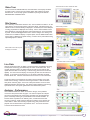
1
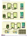
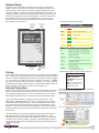
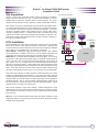
® SolarVu for Eaton PV250 5kW Inverter Installation Guide Site Preparation SolarVu® is an energy portal that enables remote monitoring of renewable energy generation sites over the web. It requires the installation of a K135 gateway which continuously transfers data from the inverter(s). This guide explains how to connect the K135 gateway to Eaton PV250 5kW inverters. Fig 1 Internet Connection ROOFTOP SOLAR ARRAY Each inverter must have a Super RS485 communications card installed which is normally a standard feature. To access SolarVu from a browser, the inverters are connected to the internet through a Cachelan K135 gateway. The K135 connects to multiple inverters using twisted pair wire, typically cat5e, daisy chained to multiple inverters. An RJ45 ethernet jack, connected to the LAN network and 120VAC outlet for the gateway power dongle are required. The LAN must have high speed internet service to an ISP to provide a gateway to the internet as shown in figure 1. + + DC DC COMBINERS EATON PV250 INVERTERS REMOTE BROWSER ACCESS K135 Installation Mount the SolarVu enclosure with conduit to the inverter for the 4 wire RS422 serial cable, ethernet cat5e cable and 120VAC control power. Normally this enclosure will be in the same electrical room as the inverter, however, the RS422 serial cable can run long distances, over 1000 feet, if necessary. Power Supply: Temporarily unplug the K135 power dongle. Wire 120VAC control power from a suitable 15A circuit to the the internal receptacle and replace the cover securing the dongle with the reusable cable tie suppled. RS422 Serial: Consult the Eaton installation manual and figs 2, 3, 4 for wiring connections. Cat5e cable can be used (4 pairs) or a cable with 2 twisted pairs (4 wires). Connect to the screw terminals or the RJ45 jacks but not both shown in fig 4. The Rx-, Rx+, Tx-, Tx+ signals on the 2 screw terminal blocks and the RJ45 jacks are connected in parallel. Route twisted pair cable through the inverter cable entry holes away from power conductors to one set of terminals from the K135. Then daisy chain to the next inverter using the other terminals being careful to match signals as shown in fig 3. Do not connect in star configuration. K135 GATEWAY RS422 RS422 Ethernet SolarVu Servers LOCAL ACCESS CORPORATE ETHERNET LAN INTERNET FIREWALL ROUTER CABLE/DSL MODEM ISP GE788 Ensure that both switches on SW2 (left side of 485 board) are in the down position to enable RS422 communications. If left in the up position (console programming) the K135 gateway cannot connect to the inverters. For all inverters except the last one, set both switches on SW1 (right side) to the up position to disable termination. Only on the last inverter should both SW1 switches be in the down position to connect the internal 120 ohm termination resistor. This is optional and only necessary for long wire runs. Each inverter requires a unique slave address. Address assignment is done automatically by the K135 each time the inverter powers up. Unlike most other other systems, the user does not need to set any communication slave address for this inverter. Ethernet: Use a standard ethernet patch cable with RJ45 connectors of the appropriate length to connect from the K135 to the network ethernet at a RJ45 wall jack or the router/switch. SMART GRID ENERGY © 2013 Copyright CACHELAN cachelan.com [email protected] All rights reserved SolarVu® Installation Guide for Eaton PV250 Inverter 1 Fig 2 PV250 Super 485 board components location 485 comms SW2-1/2 = on, down Terminator SW1-1/2 = off, up for all inverters except last one. SW1-1/2 = on, down for last inverter RJ45 IN RJ45 OUT Terminals OUT Terminals IN GE791 Fig 3 K135 Gateway to inverters connections ethernet cable to internet Multiple inverter RS422 daisy chain connection 9 Data GR-W Tx- 2 3 4 5 S Tx+ GR 1 G Rx+ Rx- OR-W 9 SW2 *SW1 422=on down Term=on down GR-W OUT Rx- Rx+ Tx- Tx+ OR-W IN Super 485 Board IN IN OUT 5 4 8 Daisy Chain OUT Rx- Rx+ Tx- Tx+ OR-W OR GR GR-W 7 GR GR-W 3 2 Term=off up OR GR OR-W 422=on down Switch to DATA position 6 SW1 *SW2 OR Both switches in down position on all inverters (last in chain) Super 485 Board IN OUT RS422 Communication Enable 1 INVERTER #N INVERTER #1 K135 Gateway GE789 OR 8 7 6 Colors shown for Cat5e cable RS422 connection GR/GRW = twisted pair (for K135 Rx to Inverters Tx) OR/ORW = twisted pair (for K135 Tx to inverters Rx) *SW1-1/2 = on (down) on all inverters for RS422 SW2-1/2 = off (up) on all inverters except = on (down) on last inverter to enable termination SMART GRID ENERGY © 2013 Copyright CACHELAN cachelan.com [email protected] All rights reserved SolarVu® Installation Guide for Eaton PV250 Inverter 2 Fig 4 Alternative communiction wiring connections Connection Method #1 - Terminals only INVERTER #N INVERTER #1 K135 GATEWAY Daisy Chain Tx+ 2 5 8 7 IN 6 IN OUT Rx- Rx+ Tx- Tx+ IN OUT 4 9 G Rx+ Rx- 3 Super 485 Board S IN OUT 1 Tx- Super 485 Board OUT Rx- Rx+ Tx- Tx+ 2 twisted pairs Connection Method #2 - Terminals and cat5e ethernet cable INVERTER #N INVERTER #1 K135 GATEWAY Daisy Chain Tx+ 2 5 8 7 IN 6 Rx- Rx+ Tx- Tx+ IN OUT 2 twisted pairs IN OUT 4 9 G Rx+ Rx- 3 Super 485 Board S IN OUT 1 Tx- Super 485 Board Rx- Rx+ Tx- Tx+ OUT cat5 ethernet cable Connection Method #3 - cat5e ethernet cable only INVERTER #N INVERTER #1 K135 GATEWAY Daisy Chain 2 7 IN 6 Rx- Rx+ Tx- Tx+ cat5 ethernet cable RJ45 ethernet patch cable connector Viewed from pin side ORA-W ORA GRE-W BLU BLU-W GRE BRO-W BRO 12345678 PLUG T-568A T-568B IN OUT OUT Rx- Rx+ Tx- Tx+ cat5 ethernet cable GRE-W GRE ORA-W BLU BLU-W ORA BRO-W BRO Read cat5e cable type from jacket then match colors to either T-568A or T-568B using the table and illustrations 8 IN OUT 5 S IN OUT 4 Super 485 Board 9 G Rx+ Rx- 3 Tx+ 1 Tx- Super 485 Board RJ45 ethernet patch cable connector Viewed from pin side 12345678 PIN PV250 IN/OUT T-568A T-568B 1 Tx+ Gr-W 2 Tx- Gr Or-W Or 3 Rx+ GND Or-W Gr-W Bl Bl GND Bl-W 6 Rx- 7 Vcc Vcc Or Br-W Br Bl-W Gr 4 5 PLUG T-568B T-568B 8 Br-W Br GE789 SMART GRID ENERGY © 2013 Copyright CACHELAN cachelan.com [email protected] All rights reserved SolarVu® Installation Guide for Eaton PV250 Inverter 3 Network Setup On power up, the K135 looks for a DHCP server to provide it a dynamic IP address. If a PC connected to the network can automatically connect to the internet through a browser then the network is already configured to accept the K135. Otherwise consult the IT systems administrator for assistance. If a dedicated IP address, subnet mask and DNS server address are required, this needs to be entered into the K135 before shipment. Once the K135 receives its IP address it acts as a client. It will automatically try to connect to the SolarVuTM server and begin transferring data from the inverter to the server. K135 indicators and connections Factory Reset Connect to RJ45 LAN (see IP settings) Connect to 120VAC power supply RJ45 ETHERNET 5Vdc POWER 10/100 Base-T K135 Status Indicator Interpretation LED 5.0V INDICATOR STATUS NORMAL STATUS POWER ON OFF- no power ON-power OK READY ON OFF No DHCP or static IP address. Check IP settings, ethernet connection SERIAL FLASHING OFF Check RS232 to inverter connection. Inverter may be off. 100Base ON ON- 100Base, OFF- 10Base or no ethernet connection Link ON OFF No ethernet connection Power Activity Ready FLASHING FLASH - data traffic activity Serial Rx/Tx 100Base Link Act Act Data/Console Serial Port RS232 SERIAL PORT Connect to inverter COMMUNICATION MODE SWITCH Data mode - left K135 front panel label with web address and login Testing K135 GATEWAY Ensure the inverters and K135 are powered on, the ethernet cable is plugged into a network jack and the RS485 cable is connected between the K135 and the inverter. The Power and Ready lights should be on if the power supply is plugged in. The Link light on indicates the ethernet connection is working. 100Base will only be on for high speed connections; for 10Base it is off. The Act light will periodically flash showing network activity. The Serial Rx/Tx flashes when the inverter is polled by the K135 but most of the time the light is off. Internet Connection Power on the K135 and allow at least 2 minutes for communication to be established. From any internet connected computer, open the browser and type in the site address assigned for your account. This will be found on the account label shipped with the K135 and on the front panel of the K135 after the URL. Once the website is reached, the opening screen is the SITE view. Click ANALYZER > INVERTER STATUS. If there is a connection from the site, the Last Communication light will be green. The K135 gateway does not need to be connected to the inverter for this light to be green. If this indicator is red, it indicates no internet connection has been established. Check internet connections at the site by trying to browse the internet at the site with a PC connected to the network. URL: mysite.solarvu.net USER: myusername PASSWORD: mypassword IP: DHCP MAC: 00-01-95-06-E8-33 ID: SS100 070300075 v1.4.1 TYPE: Xantrex GT Check ANALYSER > INVERTER STATUS for communication Screen shots may vary by inverter type LIVE - for valid data, green status light and time received If the K135 gateway is successfully collecting data from the inverter, the Last Data Updated indicator will be green and inverter data will appear. If this indicator is red but the Last Communication indicator is green, check the serial connection to the inverter and that it is operating. When both lights are green the gages on the SITE screen will display live data and graphs will begin recording site energy output. SMART GRID ENERGY © 2013 Copyright CACHELAN cachelan.com [email protected] All rights reserved SolarVu® Installation Guide for Eaton PV250 Inverter 4 Visit www.solarvu.net for a features video Video Tour For an overview of available features, visit www.solarvu.net and play the What is SolarVu video. Each screen has a HELP button that explains how all the features work. An online help guide is available for printing under SETUP > DOWNLOADS > PRINTED HELP . Help guide Site Screen For a summary of information about the site, click the SITE menu button. On the upper left, the current charging status of the solar panels, total power being generated now and in the last 30 days is displayed. Underneath, the carbon footprint of energy equivalents is displayed since startup. Links to other websites can be left as defaults or changed in SETUP to personal preferences. The local weather is preset. Email [email protected] to have it changed. For viewing on a widescreen TV suitable for display in a public place, click the WIDE PAGE button. On the right is a slideshow for public viewing. Content can be personalized using uploaded graphics in SETUP. Site Summary Screen Select wide screen view for public display on an HDTV LIVE view shows current conditions Live Data Click the LIVE menu button to display current power being generated in the array. Actual power and energy generated today are shown on the meter dial. For a normally operating system, the status indicator should be green with the last update time less than 15 minutes ago. Lifetime energy and revenue are shown digitally. For correct revenue display, the sell price per kWh must be entered in SETUP. If connection to the site is lost, or if an alarm is detected, the status indicator will be red. Click the Listen button with sound on for more information. Trends are shown for the lifetime of the system using the graphs on the right. Select either an Energy or Revenue view using the button. Click the desired time period under the graph. Scroll over a data point with the mouse for more detailed information about that day. The carbon footprint pulldown gives energy equivalents for the solar power generated for the selected time period. Analyzer - Performance Click the ANALYZER menu button and select a category in the pulldown menu and a time period under the graph. The carbon footprint will compute the energy equivalents to the solar energy generated over the selected time period. This helps visitors get a practical feel for the benefits available. To find the carbon equivalent for an arbitrary value, override the actual solar amount by entering a kWh value and selecting a category, then click the Calculator button. Other views including buy/sell energy use, performance and payback can be selected with in the pulldown menu. The screen will return to the last value selected on return. SMART GRID ENERGY © 2013 Copyright CACHELAN cachelan.com [email protected] All rights reserved ANALYSER - select performance views from pulldown SolarVu® Installation Guide for Eaton PV250 Inverter 5 Analyzer - Troubleshooting When problems occur with the system or to check inverter operation, click ANALYZER > INVERTER STATUS. Each inverter connected to the system with a K135 gateway will have its own display panel showing actual values sent. Remotely located technical personnel can assist in interpreting what the values are conveying. If no communication has been received from the device for more than 2 hours a No Data Available message will be shown. Click ANALYZER > INVERTER STATUS for troubleshooting For detailed analysis, it may be helpful to download all readings for the time period of interest into a spreadsheet for further analysis using SETUP > DOWNLOAD. Download printable HELP guide or actual readings for any time period Setup See K135 label for SETUP login For entering settings to configure your site, click the SETUP menu button. Enter your unique username and password from the account label. The setup screen appears showing communication status and current preference settings. Check the last communication time . It should show a time within the last 15 minutes if communication between the site and SolarVuTM server is working normally. K135 GATEWAY URL: mysite.solarvu.net USER: myusername PASSWORD: mypassword IP: DHCP MAC: 00-01-95-06-E8-33 ID: SS100 070300075 v1.4.1 TYPE: Outback Mate DATE: Feb 2009 SUPPORT: cachelan.com myusername mypassword For the payback and revenue calculators to work properly, correct parameters for energy sell rate, capacity, average insolation etc should be entered. Account > Equipment Setup is for factory use. All changes take immediate effect. The Site Setup tab is used to customize the banner, links, slideshow and system description. Click the Help button for each section for a description of the effect for each entry. For further analysis, individual energy readings for any time period can be downloaded into a spreadsheet from the DOWNLOAD section. Configure site settings in SETUP Enter the email address for each individual that wants a regular status report sent to them and select the frequency. This report will include energy and revenues for different time periods and indicate if there are any alarms. In the Password tab, include an email address to receive the Setup login password if this is forgotten. Support See the What is SolarVu? video at www.solarvu.net for a feature overview. Each screen has a HELP button with details for the items on that view. A printable HELP guide can be downloaded in SETUP > DOWNLOAD. Cachelan Technical Support For additional technical support, send an email to [email protected] or dial our support line in Toronto, Canada at 905.470.8400 SMART GRID ENERGY © 2013 Copyright CACHELAN cachelan.com [email protected] All rights reserved [email protected] 905.470.8400 x228 SolarVu® Installation Guide for Eaton PV250 Inverter 6