1
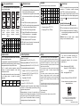
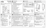
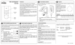
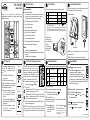
TH115 A/F/AF Owner’s Guide Thank you for choosing the Aube TH115, a programmable thermostat that provides both energy savings and comfort. TH115 Description n On/Stand By Switch GFCI Warning Light and Test Button SW3 current time. o Press DAY to set current day. For AF and F models: one of the two following messages may be displayed if the installation is incorrect: LO: The floor temperature is below 32°F (0°C), or the temperature sensor is defective, or not connected. The heating indicator is displayed and the relay is closed (energized). HI: The floor temperature is above 140°F (60°C), or the temperature sensor is defective. SW1 Day & Clock Settings a. Programming Mode b. Mode Selection/Exit Programming DN °F °C Early Start b Disable Enable Time format 12-hour 24-hour Temperature format Control module If you switch from °F to °C or vice versa, the , and setpoints may need to be redefined. When using AUTO mode, the thermostat calculates the optimum start time to obtain the desired temperature by the set time. The heating system could be started a few hours prior to set time when required. Current Mode and Setpoint Current Program Number Setpoint definition/Pre-defined Setpoints Increase/Decrease Temperature The GFCI monitors the electrical flow for any loss of current; if there is one, the thermostat will cut off power to the heating system. We recommend you test the GFCI immediately after installing the control module, and once a month thereafter to ensure it is operating properly. To test: Switches are located on the rear of the control module. To modify any setting, switch UP or DN. heating indicator • Successful: the TEST warning light is ON and power to heating system is cut off. • Unsucessful: the TEST warning light is OFF. Cut power to heating system from the main power panel and call customer service. p When successful, reset thermostat (Stand By/On) to power the heating system. NOTE: If the test warning light comes ON during normal operation, cut power to heating system from the main power panel and have an electrician verify the installation. NOTE: Keep the thermostat's air vents clean and free from obstructions. Temperature Setpoint Operating Modes The following temperature setpoints are pre-programmed: Symbol Description Default A/AF F Comfort (when at home) 70°F 82°F Economy (when asleep/ away from home) 64°F 68°F 50°F 50°F Vacation (during until the is displayed. o Press TEST: Power base NOTE: The screw cannot be removed completely. n Increase the temperature Incorrect UP a Align the bracket tabs on the control module with the holes located on top of the power base. Room OR Floor Temperature GFCI Test (GA & GB power base only) n Press HOUR - MIN to set the Function SW2 A Controls the Ambient temperature. AF Controls the Ambient temperature and Floor temperature limit. F Controls the Floor temperature. Correct # Use this switch to put the thermostat in sleep mode when its use is no longer required (e.g. summer). This will not affect the clock or programming. Models When power is applied for the first time, the LCD displays: 0:00, MO (Monday), and temperature (room/ floor). Control Module Installation This thermostat is factory-set to the following values: Buttons and symbols o p q r s t u v w First Power ON Switch Selection prolonged absence) New Automatic —Executes the schedule. n Press MODE until is displayed. The current program number is displayed. You can temporary bypass the current program by setting a specific temperature or by pressing on a pre-defined setpoint button ( ). The new setpoint will be maintained until the beginning of the next program. To modify a setpoint: n Set the desired temperature using o Press and Hold the or or . button until symbol is displayed. p Press RET to exit. and hold while switching from ON to Stand By then back to On. —Maintains a constant temperature. n Press MODE until o Set temperature is displayed. or press ( ) to use pre-defined setpoint. Floor temperature limit—The floor temperature limit is 82°F. To modify this limit: n Press Manual o Set temperature p Press RET to exit. To avoid damaging your floor, we recommend you follow the supplier’s instructions. Vacation —Maintains the Vacation setpoint during a prolonged absence. Press until the icon is displayed. 920-115-007-00-1-A Pre-programmed Schedule Modify the Schedule The TH115 programmable thermostat is pre-programmed with the following schedule: Notes: You can program up to 4 different programs per day. Each day can have different programs. It is sometimes faster to program the same schedule for the entire week and then to modify the exception days. To modify: n Press PGM to access the programming mode o Press DAY to select the day to be programmed (hold for 3 seconds to select all days of the week). Time you wake up and desired temperature Programs Time you leave and temperature during your absence Time you return home and desired temperature Time you go to bed and overnight temperature MO TU WE TH FR SA SU 6:00 6:00 6:00 6:00 6:00 6:00 6:00 8:30 8:30 8:30 8:30 8:30 --:-- --:-- 16:00 16:00 16:00 16:00 16:00 --:-- --:-- p Press PGM to select the program number. q Press HOUR and MIN to set the time or press Custom Grid Remote Input Use this blank grid to record your new schedule. Prog Setpoint MO TU WE TH FR SA SU F AF Temperature display: °F °C Time display: 12hrs 24hrs Model: A The TH115 is equipped with a remote input which allows connection of a telephone controller (accessory Aube CT240) or any other remote control system. When a signal is received through this input, the TH115 will automatically switch from normal operating mode to Vacation mode ( ), and vice versa when the signal is removed. Activating the Vacation mode There are two ways to activate the Vacation mode: n From the thermostat, see “Operating Modes” above. o From a telephone (remote location). For details on how to activate using a telephone, refer to the CT240 Instruction Manual. CLEAR to clear the time (--:-- is disregarded). r Repeat steps 2 to 4 for remaining programs. s When completed, press RET to exit mode. WARNING: When the Vacation mode is activated remotely, it must be deactivated remotely. NOTE: After 60 seconds of inactivity, the thermostat will automatically exit programming mode. 23:00 23:00 23:00 23:00 23:00 23:00 23:00 Temperature Control Technical Specifications Warranty The TH115 thermostat works differently than conventional electromechanical thermostats. It is equipped with a proportional integral adaptive (P.I.A.) controller which determines heating cycles by analyzing the temperature behavior history within the room. The P.I.A. controller reduces temperature variations providing an accurate temperature control while increasing user comfort. The controller determines the amount of power required by the heating system to maintain the setpoint temperature. Model: TH115 A / AF / F AUBE TECHNOLOGIES INC. ONE (1) YEAR LIMITED WARRANTY Display range: 32°F to 140°F (0°C to 60°C) Setting range (ambient): 40°F to 86°F (5°C to 30°C) Setting range (floor limit): 40°F to 104°F (5°C to 40°C) Pre-programmed temperature setpoints: Comfort: Economy: A/AF: 64°F (18°C) and F: 68°F (20°C) A/AF: 70°F (21°C) and F: 82°F (28°C) Vacation: A/F/AF: 50°F (10°C) Floor limit:AF: 82°F (28°C) Accuracy:± 0.9°F (0.5°C) 1 to 20% 21 to 40% 41 to 60% 61 to 80% 81 to 100% Storage:-4°F to 120°F (-20°C to 50°C) Temperature control: Proportional integral adaptive, 15-minute or 15-second heating cycles according to the application and power base. Memory backup: In the event of a power failure, an internal circuit will maintain the programming. Only the time will have to be set if the power failure is more than two (2) hours. The thermostat will return to the same operating mode as set before the power failure. This product is guaranteed against workmanship defects for a one year period following the initial date of purchase. During this period, AUBE Technologies Inc. will repair or replace, at our option and without charge, any defective product which has been used under normal conditions. The warranty does not cover delivery costs and does not apply to products poorly installed or randomly damaged following installation. This warranty cancels and replaces any other manufacturer's express or implied warranty as well as any other company commitment. AUBE Technologies Inc. cannot be held liable for related or random damages following the installation of this product. The defective product as well as the purchase invoice must be returned to the place of purchase or mailed, prepaid and insured, to the following address: If you have any questions concerning the installation or programming of the TH115 programmable thermostat, call our technical support team at: Phone: Montreal area:(450) 358-4600 Canada / U.S.:1-800-831-AUBE (2823) Fax: (450) 358-4650 Email: [email protected] Monday to Friday from 8:30 AM to 5:00 PM EST For more information on our products, visit us at: www.aubetech.com Aube Technologies Inc. 705 Montrichard Saint-Jean-sur-Richelieu, Quebec, Canada J2X 5K8 ® As an ENERGY STAR partner, Aube Technologies has determined that this product meets the ENERGY STAR guidelines for energy efficiency. 04/08/2003 920-115-007-00-1-A PB112-024T-15S Installation Instructions 24 V Low-Voltage Power Base n Applications 1. The PB112-024T-15S power base can be used on any TH11x series thermostat (with the exception of the TH110 model). This low-voltage power base operates on 15-second cycles and can be connected to a line-voltage load using a solid-state relay. The PB112-024T-15S is compatible with most solid-state relays; however, the following Aube relays are optimized for use with this power base: • RT850 solid-state relay (SSR) • RT850T solid-state relay (SSR) with built-in 24-V transformer s t u Install the control module onto the base. Apply power to the heating system. Verify the installation by checking that the heating system can be turned on or off using the thermostat. 4.1 Single SSR with Built-in Transformer WARNING Electrical Panel This power base MUST be used ONLY with solid-state relays. The use of electromechanical relays will result in reduced life expectancy and in the possibility of overheating of these devices. Blue Red Black o n o p Two (2) plastic anchors Two (2) mounting screws q Installation Guidelines Installation Procedure 4. n Turn off power to the heating system at the main electrical panel to avoid electrical shock. o Wire the base according to your application. See typical wiring diagrams in sections 4.1 and 4.2. p For a floor heating system installation, connect the floor sensor between the S and R terminals. q Secure the base to the wall using the provided screws and wall anchors. Configure the switches located on the control module (if any). Refer to the user guide. PB112-024T-15S Black 3. The installation must be carried out by an electrician and comply with local electrical codes. r Multiple SSRs with External Transformer Electrical Panel For a new installation, choose a location about 1.5 m (5 ft.) above the floor. The thermostat must be installed on an inside wall facing the heating system (except for floor heating systems). Avoid locations where there are air drafts (top of staircase, air outlet), dead air spots (behind a door), direct sunlight or concealed chimney or stove pipes (except for floor heating systems). 4.2 Heater One (1) power base p Supplied Parts 2. Heater External 24 V Transformer Red Black Heater r Red Technical Specifications 5. Maximum load: 0.5 A / 24 VAC Heating cycle length: 15 seconds Operating temperature: 32°F to 122°F (0°C to 50°C) Storage: -4°F to 122°F (-20°C to 50°C) Size (H • W • D): 124 x 70 x 23 mm (4.89 x 2.76 x 0.91 in) Wire gauge: 14 to 22 AWG 400-112-024-A 18/1/06 1/1