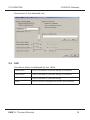
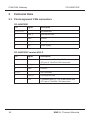
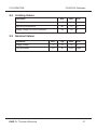
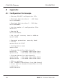
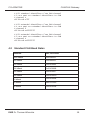
1
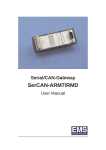
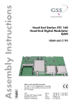
CAN/CAN-Gateway
CG-ARM7/D/E
User Manual
(preliminary)
CAN/CAN Gateway
CG-ARM7/D/E
User manual CG-ARM7/D/E
Document version:
Documentation date:
1.01
October 06th, 2009
No part of this document or the software described herein may be
reproduced in any form without prior written agreement from EMS Dr.
Thomas Wünsche.
For technical assistance please contact:
EMS Dr. Thomas Wünsche
Sonnenhang 3
D-85304 Ilmmünster
Tel. +49-8441-490260
Fax +49-8441-81860
Our products are continously improved. Due to this fact specifications may
be changed at any time and without announcement.
WARNING:
2
EMS hardware and software may not be used in
applications where damage to life, health or private
property may result from failures in or caused by
these components.
EMS Dr. Thomas Wünsche
CG-ARM7/D/E
CAN/CAN Gateway
Content
1
2
3
4
Overview
5
1.1 Features
1.2 General Description
1.3 Ordering Information
5
5
6
Handling
7
2.1 Connection
2.2 Operation
2.3 Configuration
2.3.1 Configuration File
2.3.2 Programming the Device
2.4 LED
7
7
7
7
14
15
Technical Data
16
3.1 Pin Assignment
3.2 Limiting Values
3.3 Nominal Values
16
17
17
Appendix
18
4.1 Configuration File Example
4.2 Standard CAN Baud Rates
18
19
EMS Dr. Thomas Wünsche
3
CAN/CAN Gateway
CG-ARM7/D/E
THIS PAGE INTENTIONALLY LEFT BLANK
4
EMS Dr. Thomas Wünsche
CG-ARM7/D/E
1
CAN/CAN Gateway
Overview
1.1 Features
• Connection of CAN subnetworks with differing data rates
• Filtering and buffering of data traffic
• Support for 11 bit and 29 bit identifier
• Microcontroller NXP LPC2119 with 2 internal CAN controllers
• USB interface for configuration and firmware download
• Extended supply voltage range
• Extended temperature range
• Optional (Version HS/LS) with 1 high speed (82C251) and one low speed
(TJA1054) transceiver available
• Optional (Version LS/LS) with 2 low speed (TJA1054) transceiver available
1.2 General Description
The CAN/CAN-Gateway CG-ARM7/D/E is designed for applications
where there is demand for high flexibility. Both the supply voltage
range and the operating temperature range are extended in a way
that the use in automotive applications is possible. With the
development kit and the ability to use its USB interface for download
and power supply purposes CG-ARM7/D/E performs as a versatile
development platform for CAN/CAN gateway applications. Firmware,
which has been developed on this device can also be run on CGARM7/RMD and CG-ARM7/GTI.
Among the available functions of the standard firmware are data rate
adaption, message filtering as well as identifier conversion between
the coupled busses. The restriction of the maximum data rate
depending on cable length for single CAN segments can be
abolished for the over-all system by use the CG-ARM7/D/E.
Bandwith adaption from high speed to low speed CAN systems is
inherited from the filtering capability for the version HS/LS with one
high speed and one low speed CAN transceiver.
CG-ARM7/D/E obtains its potential through the use of a 32 bit
microcontroller with 48MHz clock. High speed processing and low
latencies allow the use with high data rates and busloads.
EMS Dr. Thomas Wünsche
5
CAN/CAN Gateway
CG-ARM7/D/E
1.3 Ordering Information
6
12-20-414-20
CG-ARM7/D/E
12-20-412-20
CG-ARM7/D/E Version HS/LS
12-20-415-20
CG-ARM7/D/E Version LS/LS
EMS Dr. Thomas Wünsche
CG-ARM7/D/E
2
CAN/CAN Gateway
Handling
2.1 Connection
CG-ARM7/D/E has a male and a female SUB-D 9 plug to connect
two CAN segments. An USB type B connector is intended for
configuration purpose and for download of new firmware. Power may
be supplied to the device either via the SUB-D or the USB
connector. For the HS/LS version the CAN connection has a slightly
different connection scheme. The assignment is described in chapter
"3.1 Pin assignment".
2.2 Operation
To start up the gateway just connect the power supply, the device
starts up automatically. As soon as the automatic diagnostic process
is successfully completed the green power LED lites up permanently.
Important note: Ex factory the device offers no configuration and
must be configured before its first run. Configuration instructions for
the gateway are located in chapter "2.3 Configuration".
2.3 Configuration
The gateway configuration process consists of two steps:
• Creating a configuration file
• Loading the configuration into the device
2.3.1 Configuration File
The configuration file is a text file with the extension *.gcf. This file
holds all data needed by the gateway for operation. A complete
sample configuration is located in chapter "4.1 Configuration File
Example".
The values can either be entered in decimal or hexadecimal
notation. Using the hexadecimal notation, the character 'x' has to be
entered directly before the particular value.
EMS Dr. Thomas Wünsche
7
CAN/CAN Gateway
CG-ARM7/D/E
Some parameters are optional. If they are not defined, the gateway
uses default settings.
In the following all parameters are listed and described.
comment
#
The configuration file can be provided with comments. Comments
are prefaced with the character '#' and they end with the particular
line.
Example:
# 1st comment
key = value
version
# 2nd comment
version
The version number indicates the file format of the configuration file.
It must be 1 for the actual version.
Example:
version=1
name
name assigned to the configuration
For easier identification of the programmed settings, the configration
can be labeled. The configuration name must not have more than 32
characters and must not contain space characters or tabs. If this key
is missing, no name will be assigned. If this key is missing, no name
will be assigned to the configuration. This name can be read out and
displayed by the configuration software.
Example:
configname=MyOwnConfig
8
EMS Dr. Thomas Wünsche
CG-ARM7/D/E
btr1, btr2
CAN/CAN Gateway
CAN bit timing
The bit timing key indicates the speed of the particular CAN channel.
BTR1 indicates the baud rate for CAN channel 1, BTR2 the baudrate
for CAN channel 2. Both keys must exist in each configuration file.
This keys are directly related to the CANBTR registers of the used
controller LPC2119. This allows most flexible customization of the
baudrate settings. The basic CAN clock is 48 MHz.
Example:
# CAN channel 1: 1Mbit/s
btr1 = x00140005
# CAN channel 2: 500KBit/s
btr2 = x001C0005
Standard speeds recommend by CiA are located in chapter 4.2
Standard Baudrates.
pidin, pidout
program identifier
The program identifiers (PIDs) are required for the gateway
configuration via CAN. If you do not want to program the gateway via
CAN, you can remove this keys from your configuration file.
The PIDs determine which identifiers will be used for programming
the gateway. pidin” defines the identifier the configuration software
uses to send requests to the gateway. The key "pidout” defines the
identifier which the gateway uses to reply to the configuration
software.
For CAN channel 1 and CAN channel 2 different PIDs can be set.
But it is also possible to program the gateway just via one CAN
channel. To set the identifiers for CAN channel 1 use the keys
"pidin1” and pidout1. For CAN channel 2 use the keys "pidin2” and
"pidout2.
To use a 29-bit identifier prepend the character x” before the
particular key. Without prefix 11-bit identifiers will be sent. in chapter
4.2 Standard Baudrates.
EMS Dr. Thomas Wünsche
9
CAN/CAN Gateway
CG-ARM7/D/E
Example:
# PIDs for CAN channel 1
# CAN 1: 11-bit IN-Id: 0x5
pidin1 = x5
# CAN 1: 29-bit OUT-Id: 0xA00
xpidout1 = xA00
#
#
#
#
#
PIDs for CAN channel 2
CAN 2: 29-bit IN-Id:0x6E
xpidin2 = x6E
CAN 2: 29-bit OUT-Id: 0x1FFE
xpidout2 = x1FFE
deviceid
device identifier
During the configuration process via CAN it is needed that the
device can clearly be identified inthe network. Thisprocess is based
on the serial number of the device.
If there is the need to have the configuration process independent of
the the serial number, a device id can be assigned. Then the
identification of the device depends on the device id and not on the
serial number.
Care must be taken to use a particular device id just once in a
network, if more than one gateway is used.
The device id can have values beween 1 and 99999999.
Example:
deviceid = 50
10
EMS Dr. Thomas Wünsche
CG-ARM7/D/E
password
CAN/CAN Gateway
password
Using a password, the gateway can be protected against
unauthorized access. If the key is not defined or the value is set to 0,
password protection is disabled. The password is an up to 14-digit
hexadecimal value.
The password protection supports two security levels.
For the highest level the most significan bit (56th bit) of the password
must be 1. This security level prevents any communication with the
gateway, if the device has not been unlocked with the correct
password before.
If the most significant bit is 0, reading out information about the
gateway is enabled. Changing the configuration however is not
possible.
Example:
# Security:
password=80
# Security:
password=00
busoff
high
07 05 AF D6 B0 D1
normal
07 05 AF D6 B0 D1
bus off behavior
This key specifies the period of time in milliseconds, which will pass
by until the gateway gets bus on again after a bus off condition has
occured. If this value is not defined, the device remains in bus off
state. If a bus off time of 0 milliseconds is set, the gateway tries
immediately to get bus on again.
Example:
busoff=100
EMS Dr. Thomas Wünsche
11
CAN/CAN Gateway
fil
CG-ARM7/D/E
routing
The routing settings contain the filtering and mapping rules for a
single identifier or a range of identifiers. Only specified identifier or
ranges of identifiers are transmitted and, if existend, a mapping rule
is applied. All incoming messages with identifiers to which no rule
applies are ignored (defined programming identifiers excepted).
Additionally the frame format must be set within the filtering rule.
On the left side of the assignment there are three parameters:
[inff] fil channel [outff] = ...
inff: Defines the frame format to be accepted for incoming
messages. If inff is set to 's' standard frame format is specified.
When set to 'x' extended frame format is specified.
channel: Defines the number of the CAN channel to which the rule is
applied for incoming messages; channel may be set to 1 or 2.
outff: Defines the frame format for outgoing messages. If outff is set
to 's' standard frame format is specified. When set to 'x' extended
frame format is specified.
On the right side of the assignment up to three parameters specify
the identifier of the outgoing CAN message.
... = sid [- eid] [: mid]
sid: Defines the identifier the filtering rule is applied to. If a range of
identifiers is defined, sid is the start identifier. If the prefix 'x' is added
before the value the identifier is interpreted as a hexadecimal
number.
eid: Defines the end identifier for a range of identifiers. If only a
single identifier is to be specified this value may be missing. If the
prefix 'x' is added before the value the identifier is interpreted as a
hexadecimal number.
mid: Defines the mapping identifier. This value defines to which start
identifier a single or a range of identifiers is mapped. If no mapping
is needed, this value may be missing. If the prefix 'x' is added before
the value the identifier is interpreted as a hexadecimal number.
12
EMS Dr. Thomas Wünsche
CG-ARM7/D/E
CAN/CAN Gateway
Examples:
# The received extended identifiers in the range of
# 0x30 to 0x40 via CAN channel 1 are sent via CAN
# channel 2 as standard identifiers in the range of
# 0x400 to 0x410.
xfil1s = x30 - x40 : x400
# The via CAN channel 2 received extended identifier
# 0x1FFFFFFF is sent via CAN channel 1 as extended
# identifier with the value 0x01.
xfil2x = x1FFFFFFF : x1
# The via CAN channel 1 received standard identifiers
# in the range of 0x100 to 0x200 are sent via CAN
# channel 2 as standard identifiers without remapping.
sfil1s = x100 - x200
EMS Dr. Thomas Wünsche
13
CAN/CAN Gateway
CG-ARM7/D/E
2.3.2 Programming the Device
CG-ARM7/D/E is programmed by means of the configuration
software. It offers the possibility to configure the gateway via the
USB interface. An USB cable has to be used to connect to the host
PC.
The "Program Settings" have to be set to:
• CG-ARM7
• Program configuration
• A configuration file
The "Interface Settings" have to be set to:
• Use RS232 interface
• The used PC serial interface port
• The serial baudrate used by the CG-ARM7/D/E device
Within the "Device Settings" the serial number of the CG-ARM7/D/E
has to be set. The serial number can be found on the label of the
device.
After all settings are made a click on the "Process" button starts the
download. Do not remove power from the device until the process
has finished.
14
EMS Dr. Thomas Wünsche
CG-ARM7/D/E
CAN/CAN Gateway
Screenshot of the download tool:
2.4 LED
The device status is displayed by four LEDs.
CAN1 Active
If LED is on there is CAN bus activity on channel 1
CAN2 Active
If LED is on there is CAN bus activity on channel 2
USB Active
If LED is on there is USB bus activity
Power
If on the device is supplied with power and initialized
EMS Dr. Thomas Wünsche
15
CAN/CAN Gateway
3
CG-ARM7/D/E
Technical Data
3.1 Pin Assignment CAN connectors
CG-ARM7/D/E
Pin
Signal
Description
1, 4, 5, 6, 8
nc
not connected
2
CAN_L
CAN low bus line
3
GND
Ground
7
CAN_H
CAN high bus line
9
Vcc
Power supply
CG-ARM7/D/E Version HS/LS
16
Pin
Signal
Description
1
RTL
Connected with Pin 2 by a 5k6 resistor and
RTL pin of TJA1054 CAN transceiver
2
CAN_L
CAN low bus line
3
GND
Ground*
4, 5, 6
nc
not connected
7
CAN_H
CAN high bus line
8
RTH
Connected with Pin 7 by a 5k6 resistor and
RTH pin of TJA1054 CAN transceiver
EMS Dr. Thomas Wünsche
CG-ARM7/D/E
CAN/CAN Gateway
3.2 Limiting Values
Parameter
Min.
Max.
Storage temperature
-40
80
°C
Operating temperature
-40
70
°C
Supply voltage via CAN connectors
-40
30
V
Min.
Typ.
Max.
Supply voltage
6
12
30
CAN Baudrates
10
10
1000
Unit
3.3 Nominal Values
Parameter
EMS Dr. Thomas Wünsche
Unit
V
kBit/s
17
CAN/CAN Gateway
4
CG-ARM7/D/E
Appendix
4.1 Configuration File Example
# Gateway CG-ARM7 configuration file
# Baudrate CAN interface 1 - 1000 kbps
btr1=x00140005
# Baudrate CAN interface 2 - 500 kbps
btr2=x001C0005
# Version number of configuration file
version=1
# Device ID
deviceid=120000
# Set bus off recovery time to 1000 ms
busoff=1000
# Password protection: security level
# normal
password=11 AA 33 BC
# Configuration name
name=router
# Program identifier CAN channel 1
pidin1=x1
# Standard identifier 0x01
xpidout1=x2
# Extended identifier 0x02
# Program identifier CAN channel 2
xpidin2=x10
# Extended identifier 0x10
xpidout2=x20
# Extended identifier 0x20
# Filter settings
# All standard identifiers from CAN channel
# 1 are sent as standard identifiers to CAN
# channel 2
sfil1s=x0-x7FF
18
EMS Dr. Thomas Wünsche
CG-ARM7/D/E
CAN/CAN Gateway
# All standard identifiers from CAN channel
# 2 are sent as standard identifiers to CAN
# channel 1
sfil2s=x0-x7FF
# All extended identifiers from CAN channel
# 1 are sent as extended identifiers to CAN
# channel 2
xfil1x=x0-x1FFFFFFF
# All extended identifiers from CAN channel
# 2 are sent as extended identifiers to CAN
# channel 1
xfil2x=x0-x1FFFFFFF
4.2 Standard CAN Baud Rates
Baudrate
btr1, btr2 value
1000 kBaud
0x00140005
800 kBaud
0x00160005
500 kBaud
0x001C0005
250 kBaud
0x001C000B
125 kBaud
0x001C0017
100 kBaud
0x001C001D
50 kBaud
0x001C003B
50 kBaud
0x001C0095
10 kBaud
0x001C012B
EMS Dr. Thomas Wünsche
19