1
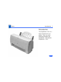
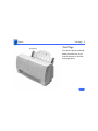
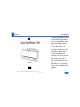
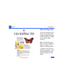
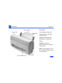
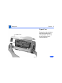
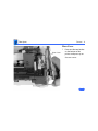
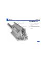
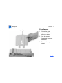
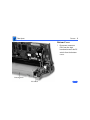
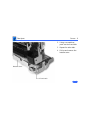
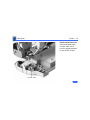
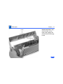
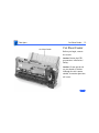
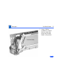
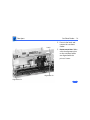
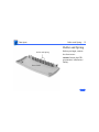
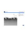
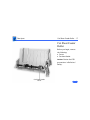
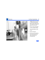
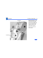
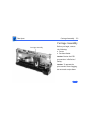
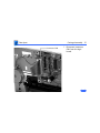
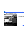
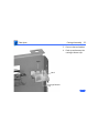
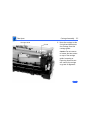
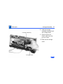
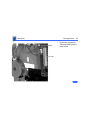
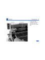
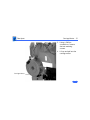
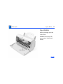
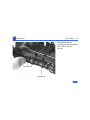
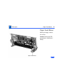
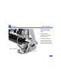
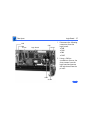
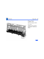
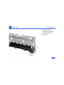
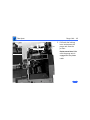
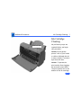
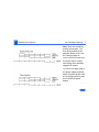
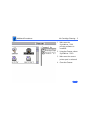
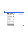
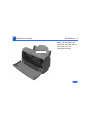
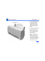
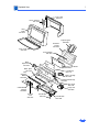
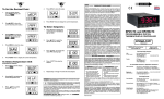
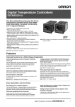
K Service Source
StyleWriter 1500
K Service Source
Basics
StyleWriter 1500
Basics
Introduction - 1
Introduction
The StyleWriter 1500 is a
high-resolution ink-jet
printer. There are some
differences between the
StyleWriter 1500 and the
StyleWriter 1200.
Basics
Introduction - 2
Hardware Differences
• The sheet feeder has changed to be compatible with the
new paper feeding scheme that the vendor has
implemented across the product line.
• The plastic cover of the controller and feed rollers has
been changed to match the paper feeder.
• There is no Error LED on the 1500
• No paper output tray
• No internal power supply, external power adapter
Basics
Introduction - 3
Software Differences
• Two additional print modes have been added to the
StyleWriter 1500: Fine and Smooth. Fine mode uses 360
dpi resolution and Smooth uses a 720 dpi horizontal by
360 dpi vertical resolution.
Basics
Introduction - 4
Color Capability
Two ink cartridges are available for the Color StyleWriter
1500. There is a black-only ink cartridge and a three-color
(Cyan, Magneta, and Yellow) that produces a composite black
as well as color.
The black-only ink cartridge is the same for both the
StyleWriter 1200 and 1500.
Basics
Test Page - 5
Online Key
Test Page
Turn on the printer and hold
down the online key for at
least 6 seconds or until the
test page prints.
Basics
Test Page - 6
The test pages show the ROM
revision and a test pattern.
There are two different test
pages; one for the threecolor ink cartridge, and one
for the black-only ink
cartridge. The black-only
test page is shown here.
Use the test pattern to
determine if the ink jets are
functioning properly. If
lines at the bottom of the
page appear broken,
proceed to the “Printing”
topic in the Troubleshooting
chapter.
Basics
Test Page - 7
Demo Test Page Units
The Color StyleWriter 1500
demo unit logic board ROM
contains a unique demo page.
A limited quantity are being
sold for use by Apple
resellers.
Note: The demo test page
printer may be serviced the
same as a regular 1500,
however, if the logic board
is replaced it will lose the
demo page capability. If that
feature is needed, the unit
should be RMAed to Finish
Goods.
K Service Source
Specifications
StyleWriter 1500
Specifications
Characteristics - 1
Characteristics
Print Methods
Serial bubble jet ink–on–demand
Print Head
1 by 64 nozzles
Print Head Life
Approximately 500 pages (normal mode)
Specifications
Graphics - 2
Graphics
Resolution
Best: 720 x 360 dpi (best mode, black and white, edge
smoothing)
360 x 360 dpi (grayscale and color)
Normal: 360 x 360 dpi
Draft: 180 x 180 dpi
Specifications
Paper Handling - 3
Paper Handling
Paper
Size: LTR, LGL, A4, Executive
Weight: 16–24 lb.
Capacity: 100 sheets (A4, LTR)
Envelopes
Size: Number 6 or 10
Capacity: 10 envelopes
Transparencies
Coated transparencies, or most inkjet transparencies
Specifications
Ink Cartridges - 4
Ink Cartridges
Type
Ink cartridge
Ink Color
Black-Only
Three-Color: Cyan, Magenta, Yellow
Life
Approximately 500 pages (black-only)
Specifications
Environmental - 5
Environmental
Acoustic Noise Level
Approximately 40 dB (reference level)
Temperature
59–86°F (15–30°C)
Humidity
10–80% (no condensation)
Specifications
Electrical - 6
Electrical
Power Source
Power Consumption
U.S./Japan: 102-132 VAC, 60 Hz
UK/Australia: 204-264 VAC, 50 Hz
Europe: 196-253 VAC, 50 Hz
Japan: 85-110 VAC, 50,60 Hz
30 W maximum
Specifications
Physical - 7
Physical
Dimensions
Weight
Height: 6.9 in. (176 mm)
Width: 13.7 in. (348 mm)
Depth: 8.5 in. (215 mm)
Approximately 5.5 lb. (2.5 kg)
K Service Source
Troubleshooting
StyleWriter 1500
Troubleshooting
General/ - 1
General
The Symptom Charts included in this chapter will help you
diagnose specific symptoms related to your product. Because cures
are listed on the charts in the order of most likely solution, try
the first cure first. Verify whether or not the product continues to
exhibit the symptom. If the symptom persists, try the next cure.
(Note: If you have replaced a module, reinstall the original module
before you proceed to the next cure.)
If you are not sure what the problem is, or if the Symptom Charts
do not resolve the problem, refer to the Flowchart for the product
family.
For additional assistance, contact Apple Technical Support.
Troubleshooting
General /Initial Startup Sequence - 2
Initial Startup Sequence
1
2
3
4
5
6
7
8
9
Plug in printer and press the power button.
Logic board is tested (ROM/RAM)
Power LED comes on
Carriage motor initialization (ink cartridge will move).
Motor starts and carriage assembly moves to home position
(slightly to the left of the purge unit).
Carriage motor detection.
• Home position detected.
• Maintenance cleaning performed.
Paper feed motor initialization.
• Paper feed motor runs.
• Pickup roller and paper lifting plate set to their initial
positions.
Ink cartridge check.
Printer is ready.
Troubleshooting
Symptom Charts /Preliminary Checks - 3
Symptom Charts
Preliminary Checks
Computer cannot find
printer
1
2
3
4
5
Print out a test page to confirm that the printer is
operational.
Verify that StyleWriter 1500 driver is installed in system
Extension folder.
Verify that serial cable is connected.
Verify continuity of serial cable and replace if necessary.
Replace logic board.
Troubleshooting
No status light or
movement
Symptom Charts /Preliminary Checks - 4
1
2
3
4
Verify that printer is turned on and plugged in correctly.
Check voltage of power adapter.
If the voltage is not 11.5 to 15.5 V replace the power adapter.
If the voltage is within the specified range, replace the logic
board.
Note: When connected to Macintosh and this error occurs, a
message will appear stating “A hardware error has occurred.
Please check for any obstructions by the Color StyleWriter
1500 ink cartridges. Press the Cancel button and try printing
again. If the error persists, see your manual.”
Troubleshooting
Symptom Charts /Carrier Movement - 5
Carrier Movement
Carrier motor does
not move or is
obstructed
1
2
3
4
5
6
7
8
Check carriage assembly for obstructions.
Check for paper jam.
Check carriage belt for wear, deterioration or dislocation.
Check to see if carriage guide frame is deformed.
Check carriage shaft for bends or scratches.
Move carriage by hand to check that it moves smoothly,
without noise.
Replace carrier assembly.
Check carriage motorresistance with ohm meter. Check
connector CNCR on the logic board.
CNCR(pins)
1-2
3-4
Resistance
7 ohms
7 ohms
Troubleshooting
Symptom Charts /Carrier Movement - 6
9
If resistance is not approximately 7 ohms replace carriage
motor. If that doesn’t solve the problem, replace logic board.
Troubleshooting
Home position error
Symptom Charts /Carrier Movement - 7
1
2
3
4
5
6
7
8
Check carriage assembly for obstructions.
Check for paper jam.
Check carriage belt for wear, deterioration or dislocation.
Check to see if carriage guide frame is deformed.
Check carriage shaft for bends or scratches.
Move carriage by hand to check that it moves smoothly,
without noise.
Replace carriage assembly.
Check carriage motor resistance with ohm meter. Check
connector CNCR on the logic board.
CNCR(pins)
Resistance
3-4
7 ohms
1-2
7 ohms
Troubleshooting
Symptom Charts /Carrier Movement - 8
9
If resistance is not approximately 7 ohms replace carriage
motor. If that doesn’t solve the problem, replace logic board.
10 After error occurs, turn the power off and observe where
the carriage stops. If it stops in the image area, then do a
home position voltage check. If the carriage stops over the
purge unit, check the purge unit.
Home position voltage
check
1
With printer on, move carriage to home position. Check
voltage at connector CNH on the logic board.
CNH (pin)
29
Carriage position
Home position
Center of printer
Voltage
4.8 V ± .2
0.15 V ± .15
Troubleshooting
Symptom Charts/Carrier Movement - 9
2
If voltages are not within specified ranges replace home
position sensor or carriage ribbon cable. If voltages are
within specified ranges, replace logic board.
Troubleshooting
Purge unit check
Symptom Charts /Carrier Movement - 10
1
Check sensor arm to see if it moves smoothly or if the sensor
arm has any deformation or damage..
Sensor Arm
Troubleshooting
Symptom Charts /Carrier Movement - 11
2
3
4
5
6
Replace logic board
Remove the purge unit from the printer and check for any
gear deformation or damage. If any gear is damaged, check the
paper feed motor for damage to the gear on the motor.
Replace purge unit.
Replace paper feed motor.
Check gears on cut sheet feeder (where the gears engage the
purge unit) for any damage or deformation.
Troubleshooting
Symptom Charts/Imaging - 12
Imaging
Ink cartridge missing
or not installed
correctly
1 Remove and reinstall ink cartridge. Execute test print.
2 Replace ink cartridge.
3 Replace logic board.
4 Replace carriage ribbon cable.
Note: The status LED may blink at the end of the initial startup
sequence when all other events have occurred correctly. When
connected to a Macintosh, a message will appear stating, “The
Color StyleWriter 1500 ink cartridge is missing or not installed
properly. Insert the cartridge properly, then click Continue.”
No printing or certain
colors won’t print
1
2
3
4
5
Remove and reinstall ink cartridge. Execute test print.
Replace ink cartridge.
Replace logic board.
Replace carriage ribbon cable.
Replace purge unit.
Troubleshooting
White lines appear
Symptom Charts/Imaging - 13
1
2
3
4
5
Remove and reinstall ink cartridge. Execute test print.
Replace ink cartridge.
Replace logic board.
Replace carriage ribbon cable.
Replace purge unit.
Troubleshooting
Ink smearing
Symptom Charts /Imaging - 14
1
2
3
4
Vertically-oriented
printed lines are
misaligned
1
2
3
Check to see if ink has misted on the platen. Use a soft, damp
cloth to clean the platen.
Check the ink nozzles to see if ink has clumped there. Clean
ink nozzle area.
Check the purge unit head wiper and head capping area. If
paper bits have clumped there, replace the purge unit.
Check paper transport parts. If ink has adhered to the parts,
paper will be smearing before it reaches the platen.
Disassemble the paper transport parts and use a soft, damp
cloth to clean.
Remove and reinstall ink cartridge.
Verify that forms thickness lever is set correctly (up for
standard paper and down for envelopes, transparencies,
labels, and heavy paper).
Replace ink cartridge.
Troubleshooting
Symptom Charts/Paper Feed - 15
Paper Feed
No paper feed
1
2
3
4
5
6
Grinding during paper
feed
1
2
3
Make sure paper path is clear of obstructions.
Check cut sheet feeder for deterioration or damage on the
rubber ring on the pickup roller, separation sheet or gears
on the side of the cut sheet feeder.
Replace paper pickup roller.
Replace cut sheet feeder.
Replace paper feed motor.
Replace logic board.
Make sure paper path is clear of obstructions.
Verify that forms thickness lever is set correctly (up for
standard paper and down for envelopes, transparencies,
labels, and heavy paper).
Verify that cut sheet feeder aligns with printer.
Troubleshooting
Symptom Charts /Paper Feed - 16
Paper feed
difficulties: binding,
tearing
1
Envelope feed
problems
1
When printing envelopes: (a) adjust paper thickness lever;
(b) do not run cut sheets and envelopes in same print job;
(c) reset paper thickness lever when finished printing
envelopes.
Spur tracks appear on
paper
1
2
Use a soft brush to clean the spurs on the front cover.
Replace front cover.
2
3
4
5
Verify that forms thickness lever is set correctly (up for
standard paper and down for envelopes, transparencies,
labels, and heavy paper).
Make sure paper path is clear of obstructions.
Verify that paper is inserted properly.
Use 16–24 lb. cotton bond paper.
Verify that cut sheet feeder aligns with printer.
K Service Source
Take Apart
StyleWriter 1500
Take Apart
Upper Case
Covers - 1
Paper Support
Covers
Logic Board
Cover
No preliminary steps are
required before you begin
this procedure.
Caution: Review the ESD
precautions in Bulletins/
Safety.
Caution: Do not use
excessive force to release a
latch or tab.
Note: This procedure covers
the removal of all the covers
on the printer.
Front Access Cover
Rear Cover
Take Apart
Covers - 2
Front Access Cover
1
Arm
2
Front Access Cover
Arm
3
Note: The front access
cover is held in place by
two arms that function
as hinges. Plastic tabs at
the end of the arms fit
into knobs on the inside
of the upper case.
Open the front access
cover.
Press the end of each
arm inward and free the
arm tabs from the
upper case.
Lift off the front access
cover.
Take Apart
Covers - 3
Upper Case
Release the right side latch
and lift the upper case a
short distance. Repeat for
the left side latch and
remove the case.
Upper Case
Latch
Latch
Take Apart
Covers - 4
Rear Cover
1
Rear Cover
Bottom Latch
Press out the two latches
on the bottom of the
printer and press up on
the rear cover.
Take Apart
Covers - 5
2
Top Latch
Top Latch
Rear
Cover
3
Release the two latches
on the top of the printer.
Lift up and remove the
rear cover.
Take Apart
Covers - 6
Logic Board Cover
Logic Board Cover
Side Latch
1
2
Press in the front latch
and release the side
latch.
Pull back and remove the
cover.
Take Apart
Covers - 7
Paper Support
Paper Support
1
2
3
Pull out the paper
support until it rests
against the stops.
Push the support
forward and disconnect
the latches.
Slide out the paper
support.
Take Apart
Covers - 8
Bottom Cover
1
Bottom Cover
DC Switch
Disconnect connector
CNV from the logic
board and remove the DC
switch from the bottom
cover.
Take Apart
Covers - 9
2
3
4
Bottom Cover
Front Latch
Using a screwdriver,
push out the front latch.
Repeat for other side.
Pull up and remove the
bottom cover.
Take Apart
Covers - 10
Replacement Note: Make
sure the bottom cover
circular tabs are fit
into the proper position
in the printer frame.
Circular Tab
Take Apart
Covers - 11
Replacement Note: Make
sure the latch on the
upper case engages the
on/off button on the logic
board.
Latch
On/Off Button
Take Apart
Cut Sheet Feeder - 12
Cut Sheet Feeder
Cut Sheet Feeder
Before you begin, remove
the covers.
Caution: Review the ESD
precautions in Bulletins/
Safety.
Caution: Do not get the ink
on your hands or clothes.
Although the ink is water
soluble, it contains dyes that
will stain.
Take Apart
Cut Sheet Feeder - 13
1
Cut Sheet Feeder
Screw
Using a Phillips
screwdriver, remove
the two screws that
secure the cut sheet
feeder to the printer.
Take Apart
Cut Sheet Feeder - 14
2
Latch
Alignment Pin
Alignment Pin
3
Press in the latch and
remove the cut sheet
feeder.
Replacement Note: Make
sure the alignment pins
on the cut sheet feeder
are aligned with the
printer frame.
Take Apart
Roller and Spring - 15
Roller and Spring
Roller and Spring
Front Cover
Before you begin, remove
the front cover.
Caution: Review the ESD
precautions in Bulletins/
Safety.
Take Apart
Roller and Spring - 16
1
Roller
2
Spring
Push the roller forward
slightly.
Carefully lift up and
remove the roller and
spring.
Take Apart
Cut Sheet Feeder Roller - 17
Cut Sheet Feeder
Roller
Before you begin, remove
the following:
• Covers
• Cut sheet feeder
Caution: Review the ESD
precautions in Bulletins/
Safety.
Cut Sheet Feeder
Roller
Take Apart
Cut Sheet Feeder Roller - 18
1
Gear
2
3
Roller
Caution: When the roller
is removed, the feeder
gear is loose. Remove the
roller slowly so that the
gear will not fly off.
Press in the two latches
on the cut sheet feeder
roller and push out the
roller.
Remove the gear.
Lift up on one end of the
roller and remove the
other end from the
mounting hole.
Take Apart
Cut Sheet Feeder Roller - 19
Line/Notch
Line/Notch
Replacement Note: Align
the notch on the upper
gear with the upper line
on the cut sheet feeder.
Align the notch on the
lower gear with the
lower line on the cut
sheet feeder.
Take Apart
Carriage Assembly - 20
Carriage Assembly
Carriage Assembly
Before you begin, remove
the following:
• Covers
• Cut sheet feeder
Caution: Review the ESD
precautions in Bulletins/
Safety.
Caution: To prevent the
print nozzles from clogging,
do not touch or wipe them.
Take Apart
Carriage Assembly - 21
Connector CNH
1
Disconnect connector
CNH from the logic
board.
Take Apart
Carriage Assembly - 22
Cable Holder
2
Remove the plastic
ribbon cable and cable
holder.
Replacement Note: Make
sure the ribbon cable
holes are mounted on the
two tabs on the inside of
the ribbon cable holder.
Ribbon Cable
Take Apart
Carriage Assembly - 23
3
4
Latch
Latch
Carriage Release
Clip
Press in the two latches.
Push up and remove the
carriage release clip.
Take Apart
Carriage Assembly - 24
5
Shaft Clip
Carefully remove the
shaft clips from each
side of the carriage
assembly.
Take Apart
Carriage Guide
Carriage Assembly - 25
Screw
6
Move the carriage to the
far right and disconnect
the carriage from the
carriage guide.
Caution: Do not remove
or loosen the two screws
on top of the carriage
guide. Loosening or
removing these screws
will cause the carriage
to go out of alignment.
Take Apart
Idler Roller
Carriage Assembly - 26
Carriage Belt
7
Using a flat-blade
screwdriver, carefully
press in the idler roller
and disconnect the
carriage belt.
Take Apart
Carriage Assembly - 27
8
Carriage Assembly
9
Hold the carriage
assembly and push back
the carriage shaft.
Gently remove the
ribbon cable from the
printer frame.
10 Slide out the carriage
shaft.
Carriage Shaft
Take Apart
Carriage Motor - 28
Carriage Motor
Before you begin, remove
the following:
• Covers
• Cut sheet feeder
Caution: Review the ESD
precautions in Bulletins/
Safety.
Carriage
Motor
Take Apart
Carriage Motor - 29
1
CNCR
CNH
Disconnect connectors
CNH and CNCR from the
main board.
Take Apart
Idler Roller
Carriage Motor - 30
Carriage Belt
2
Using a flat-blade
screwdriver, press in
the idler roller and
disconnect the carriage
belt.
Take Apart
Carriage Motor - 31
3
4
Carriage Motor
Using a Phillips
screwdriver, remove
the two mounting
screws.
Lift up and pull out the
carriage motor.
Take Apart
Eject Roller - 32
Eject Roller
Before you begin, open the
front cover.
Caution: Review the ESD
precautions in Bulletins/
Safety.
Eject Roller
Take Apart
Eject Roller - 33
Gently push back the
mounting tab and remove the
eject roller from the
printer.
Mounting Tab
Eject Roller
Take Apart
Paper Feed Motor - 34
Paper Feed Motor
Before you begin, remove
the covers.
Caution: Review the ESD
precautions in Bulletins/
Safety.
Paper Feed Motor
Take Apart
Paper Feed Motor - 35
1
2
3
Paper Feed Motor
Screws
Disconnect connector
CNV from the logic
board.
Using a Philips
screwdriver, remove
the two screws.
Carefully remove the
paper feed motor from
the printer and remove
the gear from the motor.
Take Apart
Logic Board - 36
Logic Board
Logic Board
Before you begin, remove
the covers.
Caution: Review the ESD
precautions in Bulletins/
Safety.
Take Apart
Logic Board - 37
1
CNR
CNH
Screw
Logic Board
CNV
Screw
2
CNLF
Screw
Disconnect the following
connectors from the
logic board:
• CNR
• CNH
• CNV
• CNLF
Using a Phillips
screwdriver remove the
three screws from the
logic board and remove
the logic board from the
printer.
Take Apart
Purge Unit - 38
Purge Unit
Before you begin, remove
the covers.
Caution: Review the ESD
precautions in Bulletins/
Safety.
Purge Unit
Take Apart
Purge Unit - 39
1
Purge Unit
Using a Phillips
screwdriver, remove
the screw from the
purge unit.
Take Apart
Purge Unit - 40
2
Locking Lever
Pull back the locking
lever and remove the
purge unit from the
printer.
Replacement Note: Make
sure the purge unit is
engaged into the platen
catch.
Platen Catch
Purge Unit
K Service Source
Additional Procedures
StyleWriter 1500
Additional Procedures
Ink Cartridge Cleaning - 1
Ink Cartridge
Cleaning
Ink Cartridge
No preliminary steps are
required before you begin
this procedure.
Caution: Do not get the
printer’s ink on your hands
or clothes. Although the ink
is water soluble, it contains
dyes that will stain.
Caution: To prevent the
print nozzles from clogging,
do not touch or wipe them.
The print nozzles are on the
bottom of the ink cartridge.
Additional Procedures
Ink Cartridge Cleaning - 2
Note: Check the nozzles by
printing a test page. The
lines at the bottom of the
page are shown at left. Use
the Cleaning option to
correct blurred characters,
horizontal white streaks,
and missing dots caused by
clogged ink nozzles.
To print a test page, plug in
the power adapter and hold
down the power button until
the test page starts to print,
then release the power
button.
Additional Procedures
Ink Cartridge Cleaning - 3
1
2
3
4
Make sure the
StyleWriter 1500
printing software is
installed.
Using the Chooser, select
StyleWriter 1500.
Make sure the correct
printer port is selected.
Close the Chooser.
Additional Procedures
Ink Cartridge Cleaning - 4
5
Open any document and
select the print option or
choose Print Window
from the File menu.
Additional Procedures
Ink Cartridge Cleaning - 5
6
Click the Utilities button
in the Print dialog box.
Additional Procedures
Ink Cartridge Cleaning - 6
7
Select the “Clean ink
cartridge before
printing” option and
click OK.
Additional Procedures
EEPROM Reset - 7
Logic Board
with EEPROM
EEPROM Reset
No preliminary steps are
required before you begin
this procedure.
Note: This procedure
explains how to perform the
EEPROM reset, which
clears data stored on the
logic board. It is necessary
to perform this procedure
after replacing the ink
absorbers or the logic board.
See “Logic Board” and “Ink
Absorbers” in Take Apart
for more information.
Additional Procedures
EEPROM Reset - 8
Ink Cartridge
Note: This procedure can
used with the black-only or
the three-color ink
cartridge installed.
Additional Procedures
EEPROM Reset - 9
1
Ink Cartridge
2
Disconnect the power
adapter from the
printer.
Make sure the ink
cartridge is installed and
the power adapter is
plugged into the wall.
Additional Procedures
Power Button
EEPROM Reset - 10
3
4
Press and hold down the
power button while
connecting the power
adapter to the printer
and release the power
button.
Press and hold the power
button and until the
power indicator blinks
once, then release the
power button.
Note: If the printer is
allowed to blink more
than once, the printer
goes into manufacturing
test mode. This mode is
not for service use.
Additional Procedures
Upper Corner of Pattern Page
EEPROM Reset - 11
5
Note: A pattern page now
prints and the EEPROM
data is reset. The last
bar on the pattern will
be white, which shows
that the data has been
reset.
Press the power button
to turn off the printer
and then disconnect the
power adapter from the
printer.
K Service Source
Exploded View
StyleWriter 1500
Exploded View
1
Cover, Rear
922-1918
Cover, Interface
922-1928
Case,
Upper
922-1919
Paper Support
922-2065
Cut Sheet
Feeder
922-1903
Cover, Front
922-1926
Pick-Up Roller
922-1921
Motor,
Paper Feed
922-1924
Cover, Logic Board
922-2061
Roller, Eject
922-1920
Belt,
Carriage,
Ribbon
922-1922
Logic Board
661-1111
Motor, Carriage
922-1923
Carriage Release Clip
922-0197
Clip, Shaft
922-0196
Purge Unit
922-2063
Cable Ribbon,
Carriage
922-2064
Carriage
Unit
922-1927
Feet, Bottom
922-0182
Case, Bottom
922-1925