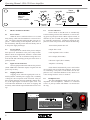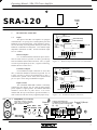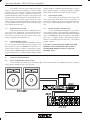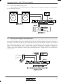
1
SRA-120 Power Amplifier Operating Manual Level (dB) -1 0 -3 - -6 -20 - -6 -20 Sig. Clip Protect Stereo Headphones Level (dB) -1 0 -3 SRA-120 Stereo Power Amplifier -10 Channel 1 (M ono) Sig. Clip -10 SRA-120 Channel 2 Channel 2 Protect Power ASHLY AUDIO INC. 847 Holt Road Webster, NY 14580-9103 Phone: (716) 872-0010 Toll-Free: (800) 828-6308 Fax: (716) 872-0739 Internet: http://www.ashly.com/ Operating Manual - SRA-120 Power Amplifier Table Of Contents 2 1 INTRODUCTION . . . . . . . . . . . . . . . . . . . . . . . . . . . . . . . . . . . . . . . . . . . . . . . . . 4 2 UNPACKING . . . . . . . . . . . . . . . . . . . . . . . . . . . . . . . . . . . . . . . . . . . . . . . . . . . . . . 4 3 AC POWER REQUIREMENTS . . . . . . . . . . . . . . . . . . . . . . . . . . . . . . . . . . . . . . 3.1 AC Voltage Requirements. . . . . . . . . . . . . . . . . . . . . . . . . . . . . . . . . . . . . . . . . . 3.2 Current Requirements . . . . . . . . . . . . . . . . . . . . . . . . . . . . . . . . . . . . . . . . . . . . . 3.3 AC Grounding Requirements . . . . . . . . . . . . . . . . . . . . . . . . . . . . . . . . . . . . . . . 4 CABLE REQUIREMENTS . . . . . . . . . . . . . . . . . . . . . . . . . . . . . . . . . . . . . . . . . . 4 4.1 Input Cables. . . . . . . . . . . . . . . . . . . . . . . . . . . . . . . . . . . . . . . . . . . . . . . . . . . . . 4 4.2 Output Cables . . . . . . . . . . . . . . . . . . . . . . . . . . . . . . . . . . . . . . . . . . . . . . . . . . . 5 5 RACK-MOUNTING REQUIREMENTS. . . . . . . . . . . . . . . . . . . . . . . . . . . . . . . 5.1 Mechanical . . . . . . . . . . . . . . . . . . . . . . . . . . . . . . . . . . . . . . . . . . . . . . . . . . . . . 5.2 Cooling . . . . . . . . . . . . . . . . . . . . . . . . . . . . . . . . . . . . . . . . . . . . . . . . . . . . . . . . 5.3 Grounding . . . . . . . . . . . . . . . . . . . . . . . . . . . . . . . . . . . . . . . . . . . . . . . . . . . . . . 5.4 Security Cover. . . . . . . . . . . . . . . . . . . . . . . . . . . . . . . . . . . . . . . . . . . . . . . . . . . 5 5 5 5 5 6 FRONT PANEL FEATURES. . . . . . . . . . . . . . . . . . . . . . . . . . . . . . . . . . . . . . . . . 6.1 Power Switch. . . . . . . . . . . . . . . . . . . . . . . . . . . . . . . . . . . . . . . . . . . . . . . . . . . . 6.2 Level Controls . . . . . . . . . . . . . . . . . . . . . . . . . . . . . . . . . . . . . . . . . . . . . . . . . . . 6.3 Signal Present Indicators . . . . . . . . . . . . . . . . . . . . . . . . . . . . . . . . . . . . . . . . . . 6.4 Clipping Indicators . . . . . . . . . . . . . . . . . . . . . . . . . . . . . . . . . . . . . . . . . . . . . . . 6.5 Protect Indicators . . . . . . . . . . . . . . . . . . . . . . . . . . . . . . . . . . . . . . . . . . . . . . . . 6.6 Headphone Jack . . . . . . . . . . . . . . . . . . . . . . . . . . . . . . . . . . . . . . . . . . . . . . . . . 6 6 6 6 6 6 6 7 REAR PANEL FEATURES . . . . . . . . . . . . . . . . . . . . . . . . . . . . . . . . . . . . . . . . . . 7.1 Inputs . . . . . . . . . . . . . . . . . . . . . . . . . . . . . . . . . . . . . . . . . . . . . . . . . . . . . . . . . . 7.2 Input Sensitivity Switch . . . . . . . . . . . . . . . . . . . . . . . . . . . . . . . . . . . . . . . . . . . 7.3 Normal/Bridging Switch . . . . . . . . . . . . . . . . . . . . . . . . . . . . . . . . . . . . . . . . . . 7.4 Stereo/Mono Switch . . . . . . . . . . . . . . . . . . . . . . . . . . . . . . . . . . . . . . . . . . . . . . 7.5 Speaker Outputs . . . . . . . . . . . . . . . . . . . . . . . . . . . . . . . . . . . . . . . . . . . . . . . . . 7 7 8 8 8 8 8 TYPICAL APPLICATIONS . . . . . . . . . . . . . . . . . . . . . . . . . . . . . . . . . . . . . . . . . 8.1 Stereo Sound Reinforcement System . . . . . . . . . . . . . . . . . . . . . . . . . . . . . . . . 8.2 Stereo Playback Monitoring System . . . . . . . . . . . . . . . . . . . . . . . . . . . . . . . . . 8.3 Mono Operation in High Level Bi-Amped System . . . . . . . . . . . . . . . . . . . . . 8 8 9 9 4 4 4 4 Operating Manual - SRA-120 Power Amplifier 9 DESIGN THEORY . . . . . . . . . . . . . . . . . . . . . . . . . . . . . . . . . . . . . . . . . . . . . . . . 10 10 TROUBLESHOOTING TIPS . . . . . . . . . . . . . . . . . . . . . . . . . . . . . . . . . . . . . . . 10.1 No Sound . . . . . . . . . . . . . . . . . . . . . . . . . . . . . . . . . . . . . . . . . . . . . . . . . . . . 10.2 Distorted Sound . . . . . . . . . . . . . . . . . . . . . . . . . . . . . . . . . . . . . . . . . . . . . . . 10.3 Excessive Hiss Noise . . . . . . . . . . . . . . . . . . . . . . . . . . . . . . . . . . . . . . . . . . . 10.4 Excessive Hum Noise . . . . . . . . . . . . . . . . . . . . . . . . . . . . . . . . . . . . . . . . . . 10 10 10 11 11 11 DIMENSIONS . . . . . . . . . . . . . . . . . . . . . . . . . . . . . . . . . . . . . . . . . . . . . . . . . . . . 11 12 SPECIFICATIONS . . . . . . . . . . . . . . . . . . . . . . . . . . . . . . . . . . . . . . . . . . . . . . . . 12 13 WARRANTY POLICY . . . . . . . . . . . . . . . . . . . . . . . . . . . . . . . . . . . . . . . . . . . . . 12 14 SCHEMATICS . . . . . . . . . . . . . . . . . . . . . . . . . . . . . . . . . . . . . . . . . . . . . . . . . . . . 13 - WARNING THIS APPARATUS MUST BE EARTHED 3 Operating Manual - SRA-120 Power Amplifier 1. INTRODUCTION Congratulations on your purchase of the Ashly SRA-120 professional stereo power amplifier. This single rack-space (1 3/4" height) amplifier delivers a substantial amount of power with exceptional audio quality and many features typically found only in larger power amplifiers, Both channels of the SRA-120 can easily drive 4 ohm loads, delivering a total of 120 watts of undistorted, average sinewave power. 3. AC POWER REQUIREMENTS 3.1 Voltage Requirements Your SRA-120 amplifier is supplied with a three conductor grounded AC power cord, and should be plugged into a standard 3-wire grounded electrical outlet which supplies 120VAC 50-60 Hz (some export models are wired for 100 or 240 volts and are labeled as such). In the event of line voltage sag, or “brown-out”, SRA120 amplifiers will continue to operate normally, albeit with less power. 3.2 The amplifier has an automatic output turn-on delay and instantaneous output turn-off to protect speakers from transients. Each output will also turn off if it "sees" a load of 2 ohms down to a short circuit. The outputs are also independently protected from overheat conditions. Each channel will automatically reset itself from any of these protection modes independent of the other channel's operation. The SRA-120 provides front panel level controls, a stereo headphone jack, and six status LED's for ease of control and monitoring. The back panel provides both balanced 1/4" jacks and balanced screw terminal inputs. Three push-button switches allow selection of stereo, mono, bridged mode, and input sensitivity, allowing the amplifier to be applied in any configuration. The amplifier's signal ground can also be lifted from chassis ground via a barrier strip jumper. 2. UNPACKING As a part of our system of quality control, every Ashly product is carefully inspected before leaving the factory to ensure flawless appearance. After unpacking, please inspect for any physical damage. Save the shipping carton and all packing materials, as they were carefully designed to reduce to minimum the possibility of transportation damage should the unit again require packing and shipping. In the event that damage has occurred, immediately notify your dealer so that a written claim to cover the damages can be initiated. The right to any claim against a public carrier can be forfeited if the carrier is not notified promptly and if the shipping carton and packing materials are not available for inspection by the carrier. Save all packing materials until the claim has been settled. 4 Current Requirements The actual AC current consumption by the amplifier depends greatly on the audio signal and the load impedance. For typical audio program material with the SRA-120 driving both channels just peaking at the clipping level, the following AC line current is drawn and should be used for system design purposes: Idle 0.1A 8Ω loads 0.6 Amps 4Ω loads 1.0 Amps Table 3.1: Estimated Maximum RMS AC Line Current Draw 3.3 AC Grounding Requirements To reduce the risk of ground loop hum, all system ground references should originate at the same point in your AC power distribution. Never remove the amplifier’s ground pin as it is both unlawful and dangerous, creating a potential shock hazard. 4. 4.1 CABLE REQUIREMENTS Input Cables Be sure to use shielded cable whether balanced or unbalanced. Shielding which is properly grounded will protect the signal from outside electrical interference such as RF, fluorescent lighting, even computer noise. As a general rule, unbalanced or single-ended (tip-sleeve) lines of less than 10 feet are satisfactory, but greater distances may require a balanced signal. Avoid running input lines in close proximity or parallel to long speaker lines, AC power cables, or power transformers, as this may generate hum or oscillation. Operating Manual - SRA-120 Power Amplifier 4.2 Output Cables The wire gauge used for speaker cables is important, in that inadequate wire gauge adds significant resistance to the speaker’s own impedance, reducing the power which is actually delivered to the speaker. It also results in a decrease in the damping factor and possible fire hazard. 5. Since power at the speaker load is a primary concern in system design, we have included a table to best determine appropriate wire gauge for your application. Table 4.1 lists the percentage of the speaker load power which would be lost in an arbitrary 100 ft. run of 2-conductor cable. This table expresses the power loss as a percentage of the load’s power rather than the total amplifier output power, so that you can use this table to accurately determine power loss to the load at other cable lengths. For example, if you plan to deliver 100 watts to an 8Ω load through 50 ft of 14 ga. cable, the power loss in the cable would be 3.2% ÷ 2 = 1.6% of 100 watts or 1.6 watts lost in the cable. Table 4.1 also gives the resistance per 100 feet of common copper wire gauges. 5.2 5.1 Mechanical All Ashly amps are designed to fit in standard 19-inch racks. Avoid placing the amp immediately next to devices which are sensitive to heat or magnetic fields (high-gain preamps, magnetic data storage, etc.) Cooling The SRA-120 will cool more efficiently with space above and below the chassis, although most applications will not require this. The following chart indicates maximum BTU per hour under varying load conditions, so that accurate assessment of room ventilation needs can be made. Thermal output is approximated by subtracting audio output power from the total power consumption of the amplifier. All values assume the amplifier is driving both channels and just peaking at the clipping level. Wire Gauge Ω/100ft 8Ω load 4Ω load 2Ω load #8 #10 #12 #14 #16 #18 .0605Ω .1018Ω .1619Ω .2575Ω .4094Ω .6510Ω 0.8% 1.3% 2.0% 3.2% 5.1% 8.1% 1.5% 2.5% 4.0% 6.4% 10.2% 16.3% 3.0% 5.1% 8.1% 12.9% 20.5% 32.6% Table 4.1: Percentage of speaker load power lost in 100 foot run of 2-conductor cable. RACK-MOUNTING REQUIREMENTS Idle 40 BTU 8Ω loads 200 BTU 4Ω loads 320 BTU Table 5.2: Maximum BTU per hour (both channels driven) 5.3 Grounding In some installations where a sound system is sensitive to RF noise or system-induced oscillation, it may be necessary to ground the amplifier's chassis to the rack enclosure. This is accomplished using star type lockwashers on the four rack mounting screws. These star washers will penetrate through the amplifier's paint to adequately ground the chassis to the rack. 5.4 Security Covers For installations where it is desirable to protect the front panel level controls from tampering or accidental misadjustment, use an Ashly security cover. Installation is simple and does not require removal of the equipment from your rack. See your Ashly dealer for details. 5 Operating Manual - SRA-120 Power Amplifier Level (dB) -3 SRA-120 Stereo Power Amplifier -1 -6 -20 - -6 -20 Sig. Clip -10 FRONT PANEL FEATURES Sig. Clip -10 Channel 1 (Mono) 6. 0 -3 - Protect Stereo Headphones Level (dB) -1 0 Channel 2 6.5 6.1 Power Switch When the unit is switched on there is a 2 second delay, during which time the PROTECT circuit will activate. The load is disconnected during this power-up sequence . When turning off the amplifier, the load is removed instantly, and the protect LED will briefly turn on as the power supply discharges. Protect Indicators Protect mode in the SRA-120 is automatically activated during extreme fault conditions, as well as during power-up and power-down. When in protect mode, as indicated by the red LED, the speaker output terminals are internally disconnected. Conditions causing the amplifier to switch into protect mode include the following: Turn-on delay/Instant turn off 6.2 Level Controls Front panel level controls allow precise independent input level attenuation to the power amp sections. When in mono or bridged mode, channel 1 controls both power amp channels. We recommend setting these controls full CW and controlling system gain at the mixer or preamp instead. Output short circuit 6.3 Amplifier overheating Signal Present Indicators Green signal present LED's indicate the presence (about 30dB below maximum output) of signals into the power amp circuitry. 6.4 Clipping Indicators Clipping occurs when the signal peak levels extend beyond the available power supply rails, essentially “cutting off” the crest portion of the waveform. This produces signal distortion and can potentially damage drivers, as the signal begins to look like a square wave. The red CLIP LED's illuminate at the onset of clipping, and accurately track both the output load and the AC line voltage. Load impedance below 2 ohms DC at output (below 8Hz) Ultrasonic signal (above 20KHz) Each channel automatically resets itself within one second of removal of the fault condition. In the event of overheating, it may take several minutes for the amplifier to reset. If thermal shutdown occurs, check to see if the cooling fins have access to fresh air. 6.6 Headphone Jack The Stereo headphone output jack will drive any impedance stereo headphones. Channel 1 is connected to the 1/4" jack tip contact and channel 2 is connected to the ring. MDA 3A SRA-120 Made In USA TO REDUCE THE RISK OF ELE CTRIC SHOCK DO NOT REMOVE COVER. NO USER SERVICEABLE PARTS INSIDE. REFER SERVICING TO QUAL IFIED SERVICE PERSONNEL. TO REDUCE THE RISK OF FIRE REPLACE ONLY WI TH SAME T YPE FUSE. TO REDUCE T HE RISK OF FIRE OR ELECTRIC SHOCK DO NOT EXPOSE T HIS EQUIPMENT TO RAIN OR MOISTURE. AVIS: RISQUE DE CHOC ELECTRIQUE NE PAS OUVRIR. 6 120VAC 50-60Hz 350W Ch.2 Outp Operating Manual - SRA-120 Power Amplifier SRA-120 7. Channel 2 Protect Power REAR PANEL FEATURES Tip (+) Ring (-) Sleeve (Ground) 7.1 Inputs The input of the SRA-120 amplifier is equipped with balanced 1/4" tip-ring-sleeve (TRS) phone jacks and balanced screw-terminal inputs. Each channel's connectors are internally wired in parallel and may be used with balanced or unbalanced connections. The nominal input impedance (balanced) is 20KΩ and the maximum input level is +22dBu. Stereo Phone Plug used for balanced Pins are numbered in the connector insert. 2 = (+) 3 = (-) 1 = (gnd) XLR Male Input Output Terminal Strip Balanced Inputs It is recommended that balanced input connections be used whenever possible to reduce ground-loop and environment-induced hum and noise. The (+) signal is on the tip of the phone jack, the (-) signal is on the ring, and the shield is on the sleeve. Unbalanced Inputs If an unbalanced input connection is used, then the (-) connection should be connected to ground. Use of a mono (tip-sleeve) plug will automatically tie the (-) connection to ground. Never float (leave unconnected) pin 2 or pin 3 when using an unbalanced signal. Input Ground The CHASSIS GROUND terminal is internally connected to the chassis, the AC earth ground, and the power amplifier’s signal ground. The INPUT GROUND terminal is tied to the 1/4" jack's sleeve. It is recommended that the input and chassis ground terminals remain connected with the factory-supplied jumper strap. tput Ch.1 (+) (-) Bridged Mode: Use Red Binding Posts Only. Chan.2 is (+) and Chan. 1 is (-). Do Not Connect Either Output to Ground. Stereo Norm 0dB Mono Bridged -10dB 45W/Ch.@8 60W/Ch.@4 Channel 2 Input Input Sensitivity (-) (+) (-) Chassis Ground (+) Signal Ground Balanced Audio Connectors Figure 7.1: Balanced Input Connections (recommended) Tip (+) Sleeve (Ground) Mono Phone Plug used for unbalanced Pins are numbered in the connector insert. 2 = (+) 3 = (gnd) 1 = (gnd) XLR Male Input Output Terminal Strip (gnd) (+) (gnd) (+) Chassis Ground Signal Ground Unbalanced Audio Connectors Figure 7.1a: Unbalanced Input Connections Input is active balanced. If unbalanced connection is used, be sure to ground unused path. (-) (+) (-) Channel 1 (Mono) Input (+) Input Ground 7 Operating Manual - SRA-120 Power Amplifier In situations where the power amp and its signal source are separated by great distances, a ground voltage difference may exist between the amp’s chassis ground and the input cable’s ground. Connection of these two grounds through the jumper strap may cause large ground currents to flow (which is known as a ground loop), causing a hum noise in the amp’s output. Unless you have such a situation with a hum problem that cannot be solved by using balanced input connections, the ground jumper strap should remain in place. and the channel 1 red binding post becomes the (-) out-ofphase speaker terminal. To properly operate in bridged mono mode, the Mono switch must also be selected. 7.2 7.5 Input Sensitivity Switch This switch selects between a 0 dBu input sensitivity in the "out" position for use with professional audio sources, and -10 dBu input sensitivity in the "in" position for use with low line-level sources such as tape decks, CD players, DAT machines, etc. 7.3 Normal/Bridging Switch This switch selects between NORMAL mode in the “out” position where both outputs are in-phase with their respective inputs, and BRIDGED mode in the “in” position where channel 1 output is switched out of phase with it's input. In BRIDGED mode, the channel 2 red binding post becomes the (+) in-phase speaker output terminal 8. 8.1 7.4 Stereo/Mono Switch This switch selects between stereo mode in the "out" position and mono mode in the "in" position. In mono mode, channel 1 input is sent to both amplifier channels, and is controlled through the channel 1 level control. Speaker Outputs - Binding Posts A pair of dual banana binding posts provide the stereo speaker outputs. The minimum load impedance is 4 ohms per channel in normal mode, and 8 ohms in bridged mode. In BRIDGING mode, the channel 2 red binding post is the (+) in-phase speaker output terminal and the channel 1 red binding post becomes the (-) out-of-phase speaker terminal. CAUTION! NEVER CONNECT THE TWO RED BINDING POSTS TOGETHER OR CONNECT EITHER RED BINDING POST TO A BLACK BINDING POST! TYPICAL APPLICATIONS Stereo Sound Reinforcement System In this situation, the audio source feeding the SRA-120 is a professional level (0dBu) stereo mixer. All three mode switches should be in the "out" position. 8 Operating Manual - SRA-120 Power Amplifier 8.2 Stereo Playback Monitoring System Here the SRA-120 is fed from a low line-level (-10dBu) stereo tape machine or CD player. Only the sensitivity switch should be depressed. 8.3 Mono Operation in High Level Bi-Amped System Here the SRA-120 is fed from the high frequency output of a professional two-way crossover. The stereo/ mono and normal/bridged switches are both depressed to obtain the maximum amount of power when amplifying a mono signal. In this mode, the channel 1 input feeds both sides of the amp, but the phase of channel 1 is inverted so the voltage difference between the channel 2 and channel 1 red binding posts is twice as great as either would be relative to the black binding posts. The (+) in-phase speaker connection is then made to the channel 2 red binding post and the (-) out of phase speaker connection is made to the channel 1 red binding post. (Warning: the output power available to the horn or loudspeaker is doubled when in bridged/mono mode. Some horn drivers may be damaged by excessive power.) 9 Operating Manual - SRA-120 Power Amplifier 9. DESIGN THEORY Ashly engineers set out to design a single rack space stereo power amplifier delivering a minimum of 120 watts total with the sonic excellence, mechanical ruggedness and unsurpassed reliability Ashly amps are known for. These qualities were upheld while containing other important parameters such as weight, depth, serviceability and cost. The result of this design philosophy is a superior sounding all-discrete bipolar power amp section at the heart of the amp. The voltage gain stages of the amp are totally discrete transistors operating "class A" for low distortion. The output section is a full complementary bipolar push-pull stage. The active balanced input and level control stages utilize low-noise op-amps for constant input impedance with accurate, low noise level control. All integrated circuitry was kept outside the feedback loop of the power amp section to maintain excellent transient response. 10. TROUBLESHOOTING TIPS 10.1 No Audio Output • Power switch is on but not illuminated: A toroidal power supply transformer is used to minimize induced hum noise and to reduce overall weight. Epoxy sealed output relays are used to protect speakers and the amplifier from turn on transients, excessive load current and overheat conditions. A unique rear-panel sensitivity switch (0dBu or -10 dBu) is provided to interface the amp with professional line level equipment or directly with low line level tape machines and CD players. The SRA-120 is packaged in an extremely rugged one piece welded 14-gauge steel chassis. The power transformer is located near the front center of the amp to minimize front panel torsion. Channels 1 and 2 circuitry are on separate plated-through glass epoxy circuit boards with plug-in connectors for all wiring to ensure ease of servicing. Each channel has a large, extruded aluminum heat sink with vertically oriented fins for maximum convection cooling action. Amp is protecting speakers from ultrasonic signals. Disconnect input cables to see if ultrasonic signal is coming from audio source. • Protect LED remains lit and relay clicking is heard: Line fuse on rear panel is blown or power outlet is dead. Output is short circuited or load impedance is too low. Check speaker cables for shorts, increase load impedance by disconnecting some speakers. IF LINE FUSE IS BLOWN, REPLACE ONLY WITH SAME TYPE AND RATING FUSE. A high frequency oscillation in the sound system is occurring when the relays close. Turn down the input level controls to verify that the amplifier alone is not causing the problem. • Power switch is lit but no signal present indicator activity: There is no input signal applied or input level controls are turned off. NOTE: In MONO mode, channel two input is disconnected and channel one input is sent to both channels. Be sure to use good quality shielded and balanced input cable. Do not run input cables alongside output speaker wires over long lengths (i.e..through the same conduit). • Protect LED remains lit: Amp is in thermal protect mode. Loudspeakers have been disconnected until the amplifier returns to a normal temperature. The amplifier relies on convection air currents to move vertically through the side fins to keep cool. If the protect indicators come on because of overheating, mount the amplifier with air space above and below to allow convection cooling action to occur. 10 10.2 Distorted Sound • Output level meters indicate 0dB level (red CLIP LED on): Amplifier is being clipped. Reduce the signal level at the signal source. Operating Manual - SRA-120 Power Amplifier SRA-120. Isolate which piece of equipment in the audio chain is causing the noise. The audio source medium itself may contain the noise. • Signal present indicators active but clip LED is not: Applied input signal is distorted before it gets to the amp. Check to see if a piece of equipment in the signal chain before the amp is clipping. Normally the amplifier should be operated with input levels fully CW to maximize headroom in the signal source. Also check for damaged speaker drivers that could cause distorted sound. If distorted sound is still heard, there may be an internal problem. Call Ashly Audio service department at 1-800-828-6308. 10.3 11. Excessive Hiss Noise If an excessive hiss noise is heard relative to the signal level, then the amplifier may not be getting a strong enough input signal. Push the rear panel sensitivity switch to the out position and increase the output level of the audio source which feeds into the amplifier. If excessive hiss noise is still heard, then a noisy signal is being fed into the 10.4 Excessive Hum Noise This is usually caused by "ground loops" in the system wiring. In a complex sound system where there are many components separated by significant distances and where several power outlets are being used, there are many opportunities for this problem to occur. If possible, feed every component in the system from one power source with a single ground point. Use balanced input and output connections between widely separated components. If a hum noise still exists, the SRA-120 signal ground can be disconnected from its chassis ground by removing the jumper strap from the input barrier strip. If you still need help, get in touch with your Ashly dealer, or call Ashly direct: (800) 828-6308. In New York State, dial (716) 872-0010. DIMENSIONS 11 Operating Manual - SRA-120 Power Amplifier 12. SPECIFICATIONS 12.1 Output Power: 12.13 Power Requirements: 110-125VAC, 50-60Hz (240V Available) 12.14 Shipping Weight: Maximum Average Power, 0.1% THD, 1KHz RMS Watts Per Channel, Both Channels Driven 8 ohms: 4 ohms: 40W 60W 20 lbs. Specification conditions are 120VAC 60Hz at 25°C. 13. WARRANTY POLICY Bridged Mono Mode: 8 ohms: 120W FTC Continuous Power, 0.1% THD, 20Hz-20KHz RMS Watts Per Channel, Both Channels Driven 8 ohms: 4 ohms: 12.2 12.3 40W 55W Frequency Response: ±0.2dB 20Hz - 20KHz Total Harmonic Distortion (35W/ch.): .01% 1ΚΗz, 8Ω .05% 20Hz-20KHz 8Ω We thank you for your expression of confidence in Ashly products. The unit you have just purchased is protected by a limited five year warranty. To establish the warranty, you must first complete and mail the warranty card attached to your product. Fill out the information below for your records. Model Number _________________________________ Serial Number _________________________________ Dealer ________________________________________ Date of Purchase _______________________________ Dealer’s Address _______________________________ 12.4 12.5 IM Distortion (35W/ch.): (SMPTE): .01% 8Ω Output Hum And Noise: (dB below full output 20Hz - 20KHz, unweighted) >100dB _______________________________________________ _______________________________________________ Dealer’s Phone _________________________________ Salesperson ____________________________________ 12.6 Damping Factor: >200 into 8Ω, <1KHz 12.7 Full Power Input Sensitivity: switchable .775Vrms/.245Vrms 12.8 Voltage Gain: switchable 26.0dB/36.0dB OTHER INFORMATION: _______________________________________________ _______________________________________________ 12.9 Input Impedance: 20KW balanced 12.10 Bandwidth: 100KHz 12.11 Slew Rate: 20V/µS 12.12 Rise Time: 2µS 10%-90% 12 _______________________________________________ Operating Manual - SRA-120 Power Amplifier SCHEMATICS: Figure 15.1: SRA-120 Block Diagram and Wiring Diagram. 14. 13 Operating Manual - SRA-120 Power Amplifier 14 Figure 15.2: SRA-120 Channel One Schematic Diagram. Operating Manual - SRA-120 Power Amplifier Figure 15.3: SRA-120 Channel Two Schematic Diagram. 15 Operating Manual - SRA-120 Power Amplifier ASHLY AUDIO INC. 847 Holt Road Webster, NY 14580-9103 Phone: (716) 872-0010 Fax: (716) 872-0739 Toll Free (800) 828-6308 Internet: http://www.ashly.com 1997 by Ashly Audio Corporation. All rights reserved worldwide. Printed in USA 4/97 SRA Rev 3