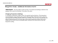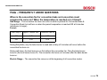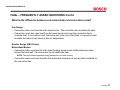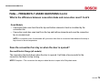
1
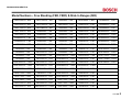
58300000118566 ARA EN A
Free Standing Range (FSR/FSR3) and Slide-In Range (SIR) Service Manual
Model Numbers
2
Interface Board – Models 50, 70, 71, 71-FSR3
40
Model Number Explanation
3
Model Number & Description
42
Installation/Service Tools
4
Control Board – FSR
43
Display at Power Up
5
Location of Components-DF, All Gas
45
Available Cooking Modes & Symbols for Elec Oven 6
Disassembly-Access to Maintop
46
Dual-Fuel & All Gas Range Top
7
Motorized Latch Assembly & Door Switch
48
All Gas Range Oven
8
Disassembly-Access to Maintop
49
Warranty
9
Resistance Checks – Element Terminals
50
All Electric Range
10
Disassembly – Touch and Turn Control
51
Dual Fuel Range
13
Access to Concealed Bake Element/Warming
52
Anti-Tip Bracket
16
Access to Oven Can and Hinge Assembly
53
Conversion of Range to LP Gas
18
Reassembly of Cooktop Control Knob
55
Door Removal
26
Calibrate the Thermostat
56
Range Operation – Oven Control
27
Range Test/Service Program
58
Voltage Checks - “Touch & Turn” Interface Board
28
Range Error Codes
68
Operation of the Electric Oven
31
Fault Codes for MTwisT Control
70
Element Cycle Charts
32
Range Error Codes-Additional Information
71
Operation of the Oven Gas Burner
34
FAQs-Frequently Asked Questions
76
Electric Top – How the Elements Heat
35
Wiring Diagrams & Schematics
80
Gas Top Operation
37
Electric Maintop Service Tips-Troubleshooting
103
How to Replace the “Touch & Turn” Board - FSR
38
Bosch Support Contact
116
June 2006
1
58300000118566 ARA EN A
Model Numbers – Free Standing (FSR, FSR3) & Slide In Ranges (SIR)
HDI7032C/U - SIR
HEI7132C/U - SIR
HES342U - FSR
HES7282U - FSR3
HGS442UC - FSR
HDI7052C/U - SIR
HEI7152C/U - SIR
HES3450U - FSR
HGS232UC - FSR
HGS445UC - FSR
HDI7132C/U - SIR
HEI7282C/U - SIR
HES345U - FSR
HGS2350UC - FSR
HGS446UC - FSR
HDI7152C/U - SIR
HES2220U - FSR
HES346U - FSR
HGS235UC - FSR
HGS5022UC - FSR3
HDI7282C/U - SIR
HES2250U - FSR
HES432U - FSR
HGS236UC - FSR
HGS5042UC - FSR3
HDS252C/U - FSR
HES2260U - FSR
HES435U - FSR
HGS242UC - FSR
HGS5052UC - FSR3
HDS255C/U - FSR
HES2320U - FSR
HES436U - FSR
HGS245UC - FSR
HGS5062UC - FSR3
HDS256C/U - FSR
HES232C/U - FSR
HES442U - FSR
HGS246UC - FSR
HGS7022UC - FSR3
HDS355U - FSR
HES2350U - FSR
HES445U - FSR
HGS247UC - FSR
HGS7052UC - FSR3
HDS442U - FSR
HES235C/U - FSR
HES446U - FSR
HGS252UC - FSR
HGS7062UC - FSR3
HDS445U - FSR
HES2360U - FSR
HES5022C/U - FSR3
HGS2530UC - FSR
HGS7132UC - FSR3
HDS446U - FSR
HES236C/U - FSR
HES5042C/U - FSR3
HGS255UC - FSR
HGS7152MX - FSR3
HDS7022C/U - FSR3
HES242C/U - FSR
HES5052C/U - FSR3
HGS256UC - FSR
HGS7282UC - FSR3
HDS7052C/U - FSR3
HES245C/U - FSR
HES5062C/U - FSR3
HGS3052UC - FSR3
HDS7062C/U - FSR3
HES246C/U - FSR
HES7022C/U - FSR3
HGS342UC - FSR
HDS7132U - FSR3
HES247U - FSR
HES7052C/U - FSR3
HGS345UC - FSR
HDS7152U - FSR3
HES252C/U - FSR
HES7062C/U - FSR3
HGS346UC - FSR
HDS7282U - FSR3
HES255C/U - FSR
HES7132U - FSR3
HGS432UC - FSR
HEI7032C/U - SIR
HES256C/U - FSR
HES7152U - FSR3
HGS435UC - FSR
HEI7052C/U - SIR
HES3052C/U – FSR3
HES7252U - FSR3
HGS436UC - FSR
June 2006
2
58300000118566 ARA EN A
Model Number Explanation
The first three letters indicate product type:
HDI - Dual Fuel SIR, HDS - Dual Fuel FSR , HEI – Electric SIR, HES – Electric FSR, HGS –
Gas FSR
The first two numbers indicate the level of features:
25 - Most features, 24 - Medium features, 23 - Standard features, 30/50 - Regular Convection,
70/71/72 – European Convection
The last number indicates the color:
2 - White, 5 - Stainless, 6 - Black, 7 - Biscuit
The next two letters….UC….Indicates United States & Canada. If model only has a U, it is not
certified for Canada.
These last two letters will be followed in production by /01, /02, /03 etc., this indicates the
service code level and must be included as part of the model number to ensure that the
correct parts are ordered for service.
June 2006
3
58300000118566 ARA EN A
Installation/Service Tools
The following list are most of the tools and parts necessary for installation and may be
necessary for service:
30 (at least) Amp Power Supply Cord Kit (not necessary for Canadian installation)
Measuring tape
Phillips head screwdriver
1¼” (31.8mm) wrench
T-20 torx screwdriver
Level
Cloth or cardboard (to protect surfaces)
Flexible conduit (for hard-wire installation only)
Torque wrench (for hard-wire installation only)
Pipe wrench
Teflon tape or pipe joint compound
Gas leak test solution
Gas supply line
Gas shut off valve (if not already present)
June 2006
4
58300000118566 ARA EN A
Display at Power Up
When the range is powered up the display shows the following for approx. 3
seconds before prompting for CLOCK:
• The orange temp display will flash ZZZ where ZZZ is the model number the control is
configured to
• For electric ranges the alpha display will flash ELC XXXX YY where XXXX indicates the Flash
version and YY is the EEPROM version
• For gas ranges the alpha display will flash GAS XXXX YY
June 2006
5
58300000118566 ARA EN A
Available Cooking Modes & Symbols for Electric Oven
DEFAULT
TEMPERATURE
TEMPERATURE
RANGE
Convection Bake
325 Deg. F
100 – 525 Deg. F
Upper, lower,
third rear
Thermal Bake
350 Deg. F
100 – 550 Deg. F
Upper and lower
Convection Roast
325 Deg. F
100 – 525 Deg. F
Upper and lower
450 or 550 Deg. F
Low or High
550 Deg. F
High (550 Deg. F)
Upper and
convection fan
0 Deg. F
100 – 300 Deg. F
Refer to all bake
models
Dehydrate
140 Deg. F
100 – 160 Deg. F
Third rear and
convection fan
Proof
100 Deg. F
85 – 110 Deg. F
Upper and lower
Sabbath
350 Deg. F
100 – 550 Deg. F
Upper and lower
Light on or off
Keep Warm
170 Deg. F
140 – 225 Deg. F
Upper and lower
COOKING MODE
Thermal Broil
Convection Broil
Temperature
Probe
SYMBOL
ELEMENTS
Upper
June 2006
6
58300000118566 ARA EN A
Dual Fuel & All Gas Range Top
Burner Ratings:
RF Burner Power-SimTM – 15,000 to a low of 1200 but with cap takes
heat output down to 400 to 500 BTUs
RR Burner 800 – 5,500
LF Burner 1,200 – 9,100
LR Burner 1,400 – 12,500
June 2006
7
58300000118566 ARA EN A
All Gas Range Oven
•
Bake…17,000 BTUs
•
Broil…14,500BTUs
•
Electronically controlled
•
Flame diffuser
•
Even heat distribution
•
Glow-bar silicon carbide igniter
•
Low profile cover for more usable cooking
surface
June 2006
8
58300000118566 ARA EN A
Warranty
• One full year Parts & Labor from date of installation or occupancy
• Additional four years part only on the following cooktop section parts – electrical controls,
heating elements and ceramic glass top.
• Service must be performed by an authorized service agency
• Warranty Claim must be submitted within 45 days of completion
June 2006
9
58300000118566 ARA EN A
All Electric Range
Electrical Connections:
Range requires a 30 Amp (at least) 120 / 240 VAC or 120 / 208 VAC dedicated circuit preferably with
a four wire connection, however where local codes and ordinances permit grounding through the
neutral and / or conversion to four wire is impractical, unit may be connected to the power supply via a
three wire connection.
Connection can be made via a range cord or a flexible conduit. If a range cord is used it must meet the
above rating requirements and be marked “For use with Ranges.”
June 2006
10
58300000118566 ARA EN A
All Electric Range Con’t
Electrical Connections
June 2006
11
58300000118566 ARA EN A
All Electric Range Cont'd
June 2006
12
58300000118566 ARA EN A
Dual Fuel Range
The gas supply line and electrical outlet must be within the spaces indicated in the illustration
below. The gas shut off valve must also be accessible without moving the range.
Instructions were determined using Standard American base cabinets measuring 36” high x 24”
deep. If nonstandard cabinets are used, care should be taken to alter dimensions accordingly.
NOTICE: Some cabinet finishes cannot service the temperatures allowed by U.L., particularly selfcleaning ovens; the cabinets may discolor or stain. This is most noticeable with laminated cabinets
June 2006
13
58300000118566 ARA EN A
Dual Fuel Range Cont'd
NOTE: When installing the regulator/valve assembly
it is easy to knock down the red tab to close off gas
flow. Be sure the red tab on the regulator is in the UP
position when work is complete.
June 2006
14
58300000118566 ARA EN A
Dual Fuel Range Cont'd
June 2006
15
58300000118566 ARA EN A
Anti-Tip Bracket - Anti-Tip bracket must be installed as shown below
June 2006
16
58300000118566 ARA EN A
Anti-Tip Bracket Installation Cont'd
June 2006
17
58300000118566 ARA EN A
Conversion of Range to LP Gas - Kit is supplied with the range
June 2006
18
58300000118566 ARA EN A
LP Conversion – Cont'd
June 2006
19
58300000118566 ARA EN A
LP Conversion – Cont'd
June 2006
20
58300000118566 ARA EN A
LP Conversion – Cont'd
June 2006
21
58300000118566 ARA EN A
LP Conversion – Cont'd
June 2006
22
58300000118566 ARA EN A
LP Conversion – Cont'd
June 2006
23
58300000118566 ARA EN A
LP Conversion – Cont'd
June 2006
24
58300000118566 ARA EN A
LP Conversion – Cont'd
June 2006
25
58300000118566 ARA EN A
Door Removal
June 2006
26
58300000118566 ARA EN A
Range Operation - Oven Control
X3
Connector to Power Relay
Board from “Touch &
Turn” User Interface
Board (clock)
Connector to “Touch &
Turn” User Interface
Board (clock) from Power
Relay Board
When the range is powered
up, the interface board
receives the voltages at X2
from the power relay board
shown in the chart on the
next page, and the clock
illuminates.
X2
This board controls all
the functions of the
oven and contains the
program data
June 2006
27
58300000118566 ARA EN A
Voltage Checks at the “Touch & Turn” Interface Board (Clock)
Voltage readings at X2 NOTE pin
connections are not marked
X2
1)
1.5 VDC
2)
0 VDC
3)
0 VDC
4)
5 VDC
5)
6)
7)
8)
0 VDC
8 VDC
0 VDC
32 VDC
Remove connector from board, set scale
to +50VDC, put one meter lead to ground
and the other lead to pins 1, 4, 6 and 8 in
turn. Voltage should read as indicated in
the chart. If voltages are good and no
display is present, replace the interface
board.
June 2006
28
58300000118566 ARA EN A
X23
X3 Wiring Harness to
Interface Board
K8
K8
X6 Latch Switches
X5 Door Switch
X7 Meat Probe
X25 Warm Drw Sensor
K10
K7
X8 Oven Sensor
K6
Lamps
K10 Convection Motor
K7
Latch Motor
N
E
U
T
R
A
L
X21 Neutral
X22 K6 out to Warming Element
X24 L1 (Red) Input to K6, K7,K8 & K10
K4
X17 L2 (Black) Input to K4
K3
X16 K4 to Bake & Conv Elements
X15 K3 out to Bake Element
X18 L1 (Red) Input to K5 & K3
X4
Ground
K5
X19 K5 out to Conv. Element
K2
X13 L2 (Black) Input to K2
X12 K2 out to Broil Element
Power Relay Board
Connections Electric Oven
K1
X11 K1 out to Broil Element
X10 L1 (Red) Input to K1
X1 L1 (Red) Input to Board
X2 Neutral (White) to Board
June 2006
29
58300000118566 ARA EN A
X3 Wiring Harness to Interface
Board
X6 Latch Switches
X5 Door Switch
X7 Meat Probe
X25 Warm Drawer Sensor
X23
K8
K8
K8
Lamps
K10
Convection Motor
K7
Latch Motor
N
E
U
T
R
A
L
K9
K10
K10
X21 Neutral
K7
K7
X22 K6 Out to Warming Element
X8 Oven Sensor
K6
K6
X24 L1 Input to K6, K7,K8 & K10
X4
Ground
Power Relay Board
Connections Gas Oven
K12
K12
X12 From K12 to Broil Valve Coil
X11
L1 Input to K11 & K12
K11
K11
X10 From K11 to Bake Valve Coil
X1
L1 (Red) Input to Board
X2
Neutral (White) to Board
June 2006
30
58300000118566 ARA EN A
Operation of the Electric Oven
1
2
3
4
Touch Bake and set temperature at the control, relay board receives input and
checks resistance of sensor. If heat is required then the following relays will close:
K3 & K4 for the bake element and K1 & K2 for the broil element. The output
voltages from the board should be as follows: X15-L1 to bake element, X16-L2 to
bake element. X11-L1 to broil element, X12-L2 to broil element. This supplies
120volts from L1 & L2 giving each element 240 volts and oven heats.
5
NOTE: See charts on next page for element “On Times”.
June 2006
31
58300000118566 ARA EN A
Element Cycle Charts
CONVECTION BAKE MODE
June 2006
32
58300000118566 ARA EN A
Element Cycle Charts Cont'd
June 2006
33
58300000118566 ARA EN A
Operation of the Oven Gas Burner
1
2
3
4
K11
Touch Bake and set temperature at the control, relay board
receives input and checks resistance of sensor. If heat is required
then Bake relay K11 is closed. 120VAC is sent to the gas safety
valve. The glow igniter which is wired in series with the valve starts
to heat up, as it does so the voltage drops across the valve. When
the glow bar draws 3.2 amps and is glowing the valve opens
sending gas to the burner and it ignites. Bake is 17,000 BTUs.
5
June 2006
34
58300000118566 ARA EN A
Electric Top - How the Elements Heat
Each element or section of an element is controlled by a relay. Touch the glass to select
element, turn knob to select the power level. For the element to heat the following relays
must close:
Left Front & Right Front
L2 from K10 measured at X30.
Left Front
L1 from K1 900 watt measured at X5
L1 from K3 800 watt measured at X7
triple element
L1 from K4 800 watt measured at X8
Right Front
L1 from K2 1200 watt measured at X6
Right Rear & Left Rear
L2 from K9 measured at X32
Right Rear
L1 from K5 1100 watt measured at X9
single element
double element
L1 from K6 800 watt measured at X12
Left Rear
L1 from K7 1500 watt measured at X11
single element
June 2006
35
58300000118566 ARA EN A
Electric Top - How the Elements Heat Cont'd
L1
L2 N
June 2006
36
58300000118566 ARA EN A
Gas Top Operation
1
2
Spark Switch
3
Sim. Light
This switch is only
for the Super-Sim
burner
Turn the control knob to the light position. The spark switch closes and sends 120VAC to the spark module.
The spark module output sends 14,000VDC to the burner igniter creating a spark to the underside of the
burner cap. The action of turning the knob to the light position allows gas to flow to the burner and it ignites
4
5
6
June 2006
37
58300000118566 ARA EN A
How to Replace the “Touch & Turn” Interface Board (Clock) - FSR
Remove the Knob (if it is a tight fit, wrap some scotch
tape around the knob & pull gently to remove)
Remove the locknut
Remove upper rear access panel, remove connector from board, remove the 4 or 6 screws holding the
board. Reassemble new board in reverse order after checking the board configuration. See next page for
instructions.
June 2006
38
58300000118566 ARA EN A
When a replacement board is ordered, all “Touch & Turn” interface boards are programmed
for the MEDIUM featured models for example HXS24XU: For the MOST featured model
HXS25XU snap off either one of these tabs.
For the LEAST featured
model example
HXS23XU, snap off both
tabs.
Note be sure to
check the model #
of the range and
configure the board
correctly before
installing.
June 2006
39
58300000118566 ARA EN A
Interface Board for All Models w/First Two Numbers of 50, 70, 71, 72
Replacement – FSR3
1.
2.
3.
For models beginning with 50, 70, 71, 72 (FSR3 and SIR) there is one interface board. To
replace the board follow the directions below:
Remove the control knob on the front of the upper back panel.
Remove the knob bezel hex nut using a 7/16” socket.
Hex nut
4.
5.
6.
7.
8.
9.
10.
Remove the upper back panel cover by removing the torx screws on the left and right sides of
the unit.
Using a Phillips screwdriver, remove the four screws of the display board and disconnect the
cable from the connector.
Insert the screws from the old board into the standoffs and HAND TIGHTEN the screws. DO
NOT USE A POWER SCREWDRIVER TO TIGHTEN THESE SCREWS. Hand tightening only
will secure the board. Over torque on these screws can cause damage to the touch
zones.
Reconnect the cable to the connector.
Reinstall the hex nut using the 7/16” socket. Again, DO NOT OVER-TIGHTEN THE HEX NUT.
A slight tug to tighten the hex nut will secure the knob bezel.
Reinstall the upper back cover.
Configure the board for the correct model.
June 2006
40
58300000118566 ARA EN A
Interface Board For All Models W/First Two Numbers Of 30, 50, 70, 71, 72
Configuration – FSR3 Cont'd
The Service Configuration Mode can be accessed only when the system is turned on and the display
shows CLOCK and “12” is flashing. Once OFF is pressed or the knob is turned access to the Service
Configuration Mode is denied and cannot be accessed unless the system is turned off and then back
on. To access the Service Configuration Mode, turn the power on and wait until the display shows the
type – ELECTRIC or GAS – and the software version.
READ THROUGH THESE STEPS BEFORE STARTING MODEL CONFIGURATION
1.
2.
3.
4.
5.
6.
Switch to the set clock mode.
Simultaneously press the LIGHT and TEMPERATURE (or BROIL if the model number begins with
30) and hold for 5 seconds.
After 5 seconds the display will show SYSTEM CONFIG and beep once.
You have 10 seconds to select START or the control will automatically return to operation.
When START is pressed the display will change to SET SYSTEM and beep once.
Starting immediately you have 10 seconds to rotate the knob to select a model or the control will
automatically return to operation. See the following page for model and corresponding number.
June 2006
41
58300000118566 ARA EN A
Model Number & Description
MODEL 1 - HEI7152C, HEI7152U
MODEL 2 - HEI7022C, HEI7022U, HEI7052C, HEI7052U, HEI7062C, HEI7062U
MODEL 3 - HDI7052C, HDI7052U, HDI7062C, HDI7062U
MODEL 4 - HDI71522U, HDI7282U
MODEL 5 - HES5022U, HES5042U, HES5052U, HES5062U, HE2224U
MODEL 6 - HES7022U, HES7042U, HES7052U, HES7062U, HE2425U
MODEL 7 - HES7132U, HES7152U, HES7252U, HES7282U, HES2528U
MODEL 8 - HES7022C, HES7042C, HES7052C, HES7062C, HE2425C
MODEL 9 - HDS7022U, HDS7052U, HDS7062U, HDS7022C, HDS7052C, HDS7062C
MODEL 10 - HGS7282UC
MODEL 11 - HES3052U
MODEL 12 - HGS3052UC
MODEL 13 - HGS5022UC, HGS5042UC, HGS5052UC, HGS5062UC
MODEL 14 - HGS7022UC, HGS7052UC, HGS7062UC, HG2415UC, HG2416UC, HG2425UC
MODEL 15 - HGS7132UC, HGS7152UC
MODEL 16 - HDS7132U, HDS1752U, HDS7282U, HD2525U
MODEL 17 - HES3052C
MODEL 18 - HES5022C, HES5042C, HES5052C, HES5062C, HE2224C
June 2006
42
58300000118566 ARA EN A
Control Board - FSR
The control board must be reassembled so 4 of the 6 standoffs (“pins”) engage the 4 holes in the
metal plate glued to the Ceran glass maintop (the other 2 standoffs don’t engage any holes in the
plate). If not, the magnetic knob & digital displays will not line up.
CAUTION: Don’t force the standoffs in place (so they’re not broken).
June 2006
43
58300000118566 ARA EN A
Control Board – FSR Cont'd
Before mounting the control board, make sure each of the 6 standoffs (“pins”) are inserted
properly into the component boards. The two boards should be parallel.
In addition, make sure there is no debris between the touch pads and the glass, and that the
pads are making good contact with the glass. If not it will not work and may show an error code.
June 2006
44
58300000118566 ARA EN A
Location of Components Dual Fuel & All Gas Range
Relay Board
Spark Module
Convection Motor
Gas regulator &
connection point
Access to warming
drawer element
terminals
Gas safety valve
June 2006
45
58300000118566 ARA EN A
Disassembly - Access to Maintop
1
2 Tabs
No need to remove 3
these screws
Slots
Remove knobs first if unit has mechanical controls or is a gas top. Remove the two screws under the front
panel, support the panel as you take out the second screw so that it won’t fall. Panel is also held in place
with two support tabs which fit into slots on sub-panel.
5
4
Remove
these
screws
June 2006
46
58300000118566 ARA EN A
Disassembly - Access to Maintop Cont'd
6
7
Remove the 12 screws
which hold the 2 rear
panels and disconnect
the ground screw from
the maintop support
Ground
Screw
Lift the maintop a couple of inches to disengage the locking tabs and slide towards the front of the unit.
Lift the front of the maintop and fold back against the control panel. (place towel or blanket over control
panel to avoid scratching panel or maintop) The elements, control, and latch assembly can now be
accessed.
8
9
10
June 2006
47
58300000118566 ARA EN A
Motorized Latch Assembly & Door Switch
Remove 2 screws from front frame
Latch Motor
Latch can be accessed from under the cooktop
Latch Switches
Plunger
Light Switch
June 2006
48
58300000118566 ARA EN A
Disassembly - Access to Maintop
Mechanical version
Touch & Turn control version
Each pair of elements
are held in place by a
single bracket & two
tension clips per
element
Retaining brackets
Tension clips
June 2006
49
58300000118566 ARA EN A
Resistance Checks - at the Element Terminals
Turn off power before beginning resistance checks
LF Triple Element 2500 Watts
Right Front Single Element 1200W
2-1 70.7 Ohms
2-4 46.3 Ohms
2-4 71.3 Ohms
2-3 63 Ohms
3
4
1
2
Right Rear Double Element 1900W
Left Rear Single
Element 1500W
2-3 50.6 Ohms
2-4 68.5 Ohms
2-4 37.3 Ohms
June 2006
50
58300000118566 ARA EN A
Disassembly - Touch & Turn Control
1
2
3
Disconnect
wires as
needed.
Remove 2 screws holding cover
4
Remove the support bracket
Support bracket is held with 2 screws
5
Lift board up and out.
6
CAUTION: Take care not to
break the plastic board
standoffs.
June 2006
51
58300000118566 ARA EN A
Access to Concealed Bake Element & Warming Element
Front
Warming
element is
removed from
front by
removing the
drawer
Rear
Remove this cover for access to the warming
drawer element terminals
Rear
Remove this cover for access to the bake element
June 2006
52
58300000118566 ARA EN A
Access to Oven Can and Hinge Assembly
1
2
3
Remove latch assembly & top panels. Remove 3 screws on top of side panel, lift up & out to disengage tabs at
the bottom. Remove screws holding outer & inner galvanized panels. Remove insulation (it is all in one piece)
oven can is easily removed from chassis by removing front and rear chassis frame screws (see instructions on
next page).
4
5
6
June 2006
53
58300000118566 ARA EN A
Access to Oven Can and Hinge Assembly – Cont'd
Remove these
screws
June 2006
54
58300000118566 ARA EN A
Reassembly of Cooktop Control Knob, Spring & Bezel
1
Assemble knob
spring & bezel.
2
Hold assembly
together and
install on shaft
3
4
June 2006
55
58300000118566 ARA EN A
Calibrate the Thermostat ( Change the Offset )
Touch cooking mode & keep
your finger on there until
“SELECT FUNCTION”
appears (about 5 secs.)
1
3
2
Using control knob, scroll
through menu until “OVEN
TEMP OFFSET” appears.
Touch START and a
number will appear in the
temperature window. If the
oven has never been
calibrated before it will be 0
degrees F
4
June 2006
56
58300000118566 ARA EN A
Using the control knob scroll through the
temperature options. The temperature ranges from
–25 degrees F to + 25 degrees F . Select the
number of degrees that the temperature needs to
be changed by and touch “START”. Display will
show “SELECT FUNCTION”, touch “OFF” to
complete the change.
5
6
7
June 2006
57
58300000118566 ARA EN A
Range Test / Service Program
The range control has a service program that can be accessed by the service technician to check
component and /or function.
To enter the service program, do the following:
Place a finger on the cooking mode, temperature and start zones simultaneously for 5 seconds… the
word “TEST” will display. Touch cooking mode and “SERVICE” will display.
1
2
June 2006
58
58300000118566 ARA EN A
Touch start and “LIGHT” will display, at this point the light function can be tested by touching start again,
or use the rotary control knob to scroll through the different test functions. To check a particular function
rotate to that function then touch start. To exit the program at any time touch cancel.
Note: During all functions the maximum oven temperature is 200 degrees F, if reached the display shows
“TOO HOT” and any function in operation stops, except the Cancel ( which allows exit from the
program).The test can be resumed once the temperature falls below 200 degrees F.
3
4
June 2006
59
58300000118566 ARA EN A
Electric Oven
Function 1:
1.
2.
3.
4.
5.
6.
7.
Display LIGHT
Press Start Zone to activate oven light relay
Display LIGHT ON
Press Start Zone to deactivate oven light relay
Display LIGHT
Allow user to continue toggling
Rotating the selection knob will deactivate the light relay (if on) and scroll display to
function select (Light, Conv Fan, Ring, etc.
Function 2:
1.
2.
3.
4.
5.
6.
7.
Display CONV FAN
Press Start Zone to activate Convection fan relay
Display FAN ON
Press Start Zone to deactivate Convection fan relay
Display FAN
Allow user to continue toggling
Rotating the selection knob will deactivate the Fan relay (if on) and scroll display to
function select (Light, Conv Fan, Ring, etc.)
June 2006
60
58300000118566 ARA EN A
Function 3:
1.
2.
3.
4.
5.
6.
7.
Display RING (if applicable for version)
Press Start Zone to activate Conv. Fan relay and Ring element relay
Display RING ON
Press Start Zone to deactivate Conv. Fan relay and Ring element relay
Display RING
Allow user to continue toggling
Rotating the selection knob will deactivate the Ring and Fan relay (if on) and scroll display
to function select (Light, Conv Fan, Ring, etc.)
Function 4:
1.
2.
3.
4.
5.
6.
7.
Display BROIL
Press Start Zone to activate Broil element relay
Display BROIL ON
Press Start Zone to deactivate Broil element relay
Display BROIL
Allow user to continue toggling
Rotating the selection knob will deactivate the fan relay (if on) and scroll display to
function select (Light, Conv Fan, Ring, etc.)
June 2006
61
58300000118566 ARA EN A
Function 5:
1.
2.
3.
4.
5.
6.
7.
Display BAKE
Press Start Zone to activate Bake element relay
Display BAKE ON
Press Start Zone to deactivate Bake element relay
Display BAKE
Allow user to continue toggling
Rotating the selection knob will deactivate the Bake relay (if on) and scroll display to
function select (Light, Conv Fan, Ring, etc.)
Function 6:
1.
2.
3.
4.
5.
6.
7.
Display WARMING DRAWER (if applicable for version)
Press Start Zone to activate Warming Drawer element relay
Display WARMING D ON
Press Start Zone to deactivate Warming Drawer element relay
Display WARMING DRAWER
Allow user to continue toggling
Rotating the selection knob will deactivate the Warming Drawer relay (if on) and scroll
display to function select (Light, Conv Fan, Ring, etc.)
June 2006
62
58300000118566 ARA EN A
Function 7:
1.
2.
3.
Display SENSOR CHECK
Press Start Zone to activate control to automatically perform self check of:
Meat probe resistance (if applicable for version)
Oven sensor resistance
Warming drawer sensor resistance (if applicable for version)
If self check finds a failure during this sensor check the alpha display shows which one with
FAILURE PROBE, FAILURE OVEN or FAILURE W D. If no failure is found, the display
shows SENSORS OK. Rotating the selection knob will deactivate the sensor check mode
and scroll display to function select (Light, Conv Fan, Ring, etc.)
Function 8:
1.
2.
3.
4.
5.
Display CHECK LATCH
Press Start Zone. Control activated door latch. Control operates as if in normal self-clean
mode, checking for switch logic and time out function. Lock icon should operate as in
normal operation. Once latch is locked, motor stops and icon is steady state. All errors
should show if malfunction or non-locking is detected. Further pressing of the Start Zone will
be ignored.
Press Start Zone. Control deactivated door latch. Control operates as if in normal self-clean
mode, with all checks, icon change (lock flashing, then off) and error detection. Further
pressing of the Start Zone will be ignored until the latch has un-locked or an error has been
detected. If an error is detected the latch motor will stop and the display will show that code
and beep.
Allow user to continue toggling.
Rotating the selection knob will deactivate the Check Latch mode and reset to home (if
locked) and scroll display to function select (Light, Conv Fan, Ring, etc.).
June 2006
63
58300000118566 ARA EN A
Gas Oven
Function 1:
1.
2.
3.
4.
5.
6.
7.
Display LIGHT
Press Start Zone to activate oven light relay
Display LIGHT ON
Press Start Zone to deactivate oven light relay
Display LIGHT
Allow user to continue toggling
Rotating the selection knob will deactivate the light relay (if on) and scroll display to function
select (Light, Conv Fan, Warming Drawer, etc.)
Function 2:
1.
2.
3.
4.
5.
6.
7.
Display CONV FAN
Press Start Zone to activate Convection fan relay
Display FAN ON
Press Start Zone to deactivate Convection fn relay
Display FAN
Allow user to continue toggling
Rotating the selection knob will deactivate the fan relay (if on) and scroll display to function
select (Light, Conv Fan, Warming Drawer, etc.)
June 2006
64
58300000118566 ARA EN A
Function 3:
1.
2.
3.
4.
5.
6.
7.
Display WARMING DRAWER (if applicable for version)
Press Start Zone to activate Warming Drawer element relay
Display WARMING D ON
Press Start Zone to deactivate Warming Drawer element relay
Display WARMING DRAWER
Allow user to continue toggling
Rotating the selection knob will deactivate the Warming Drawer relay (if on) and scroll
display to function select (Light, Conv Fan, Warming Drawer, etc.)
Function 4:
1.
2.
3.
Display SENSOR CHECK
Press Start Zone to activate control to automatically perform self check of:
Meat probe resistance (if applicable for version)
Oven sensor resistance
Warming Drawer resistance (if applicable for version)
If self-check finds a failure during this sensor check the alpha display shows which one with
FAILURE PROBE or FAILURE OVEN or FAILURE W D. If no failure is found, the display
shows SENSORS OK.
Rotating the selection knob will deactivate the sensor check mode and scroll display to
function select (Light, Conv Fan, Warming Drawer, etc.)
June 2006
65
58300000118566 ARA EN A
Function 5:
1.
2.
3.
4.
5.
6.
7.
Display BROIL
Pressing Start Zone activates Broil relay for 120 seconds
Display BROIL ON
Pressing Start Zone deactivates Broil relay
Display BROIL
Allow user to continue toggling. White Broil is on Controller times for 120 seconds. If user
does not turn off broil relay within the 120 seconds, controller turns off automatically (also
max temp of 200 F is monitored).
Rotating the selection knob will deactivate the Check Latch mode and reset to home (if
locked) and scroll display to function select (Light, Conv Fan, Warming Drawer, etc.)
Function 6:
1.
2.
3.
4.
5.
6.
7.
Display BAKE
Pressing Start Zone activates Bake relay for 120 seconds
Display BAKE ON
Pressing Start Zone Deactivates Bake relay
Display BAKE
Allow user to continue toggling. While Bake relay is on, Controller times for 120 seconds. If
user does not turn off broil relay within the 120 seconds, controller turns off automatically
(also max temp of 200 F is monitored).
Rotating the selection knob will deactivate the Check Latch mode and reset to home (if
locked) and scroll display to function select (Light, Conv Fan, Warming Drawer, etc.)
June 2006
66
58300000118566 ARA EN A
Function 7:
1.
2.
3.
4.
5.
Display CHECK LATCH
Press Start Zone. Control activates door latch. Control operates as if in normal self-clean
mode, checking for switch logic and time out function. Lock icon should operate as in
normal operation. Once latch is locked, motor stops and icon is steady state. All errors
should show if malfunction or non-locking is detected. Further pressing of the Start Zone will
be ignored until the latch has locked or an error has been detected.
Press Start Zone. Control deactivated door latch. Control operates as if in normal self-clean
mode, with all checks, icon change (lock flashing then off) and error detection. Further
pressing of the Start Zone will be ignored until the latch has un-locked or an error has been
detected. If an error is detected, the latch motor will stop and the display will show that code
and beep.
Allow user to continue toggling
Rotating the selection knob will deactivate the Check Latch mode and reset to home (if
locked) and scroll display to function select (Light, Conv Fan, Warming Drawer, etc.)
June 2006
67
58300000118566 ARA EN A
Range Error Codes
CODE
DESCRIPTION
WHEN CHECKED
FAULT LIMIT
F1
Meat probe failure during test or service
mode
Only during test or service
None
F2
Oven sensor failure during test or service
mode
Only during test or service
None
F3
Warming drawer sensor failure during test
or service mode
Only during test or service
None
F31
Oven temperature sensor failure
Cook or clean programmed
20 sec.*
F33
Warming drawer sensor failure
When warming drawer is
active
20 sec.*
F41
Motorized latch will not lock
Latch should be locked
1 min.
F43
Motorized latch will not unlock
Latch should be unlocked
1 min.
F45
Motorized latch both locked and unlocked
Always
1 min.
F111
Runaway oven temperature 585o F
Latch unlocked
5 sec.
F113
Runaway oven temperature 950o F
Latch locked
5 sec.
F120
Any key (except Cancel) pressed longer
than 60 sec.
Always
1 min.
June 2006
68
58300000118566 ARA EN A
Range Error Codes Cont'd
CODE
DESCRIPTION
WHEN CHECKED
FAULT
LIMIT
F121
Touch key voltage out of limits (except
cancel key)
Always
Max. 1 min.
F122
Selection mechanism for touch keys
faulty
Always
Max. 1 min.
F124
Cancel key pressed for more than 60
sec.
Always
1 min.
F125
Cancel touch key voltage out of limits
Always
Max. 1 min.
F141
Slave micro not functioning
Always
1 min.
F151
EEPROM failure or communication
circuit failure
Cook or clean programmed
1 sec.
F153
User interface too hot
Always
1 sec.
F154
Power board too hot
Always
1 sec.
F155
Cook profile corrupted in EPROM
Cook or clean programmed
1 sec.
F160
Cooling fan hall effect feedback not
present
Always, NTC temp in built-in
range only
1 sec.
F170
Power failure
Always
2 ms.
June 2006
69
58300000118566 ARA EN A
Range Error Codes Cont'd
CODE
DESCRIPTION
WHEN CHECKED
FAULT
LIMIT
F190
Power over voltage
At power on
F200
Time out and stop function
During production test mode
110 sec.
F210
Range exceeded safe test limits
During service test mode
200o F
* F31 and F33 fault limit set to 20 sec. to avoid erroneous faults due to line noise on long
lengths of wires of sensors.
Fault Codes for MTwisT Control
ER 22
/* Keyboard */
ER 3
/* Selection of Keys */
ER 25
/* False connection mains */
ER 26
/* Relay supply voltage too high (off state of control) */
ER 12
/* Mismatch of relay port pin and software register */
ER 13
/* Invalid EPROM data */
ER 23
/* PWM-frequency oft of limit */
ER 24
/* Wrong number of relays */l
June 2006
70
58300000118566 ARA EN A
Range Error Codes - Additional Information
LATCH FAILURE MODE
Error 41 Locking mode – All heating functions stop with error indicated
• If the latch does not lock and the control does not see a changed state of the feedback switch
(probably indicating that the motor did not rotate), the display will fault out and the latch motor shuts
off.
• If the control senses that contact A is open and B is still open (possibly due to disconnected wire or
bad switch), the control will fault out and the motor will continue to operate until the cam returns to
home position – contact A closed.
• If the control senses that contact B is closed and contact A remains closed (possibly due to bad
switch), the control will fault out and the motor will continue to operate until contact B is open again
(back to home).
Error 43 Unlocking mode – All heating functions should be off
• If the latch does not unlock and the control does not see a changed state of the feedback switch
(due to motor not rotating), the display will fault out and the latch motor shuts off.
• If the control senses that contact B is open and A is still open, the control will fault out and the motor
shuts off (should be in home position).
• If the control senses that contact A is closed and contact B remains closed, the control will fault out
and the motor shuts off.
June 2006
71
58300000118566 ARA EN A
Range Error Codes - Additional Information Cont'd
LATCH FAILURE MODE Cont'd
Error 45 Locked and Unlocked mode – All heating functions should shut off
If the control senses that contacts A and B are either both open or both closed during any operation
(cooking or self-cleaning), the display will fault out and the latch motor will not rotate until the oven temp
is below 585o F. The control will then look for contact A open and contact B closed. If it does not find
that state within 1 minute, the control will look for Contact B closed and shut off the motor.
The user can press the cancel button once and the beep will stop and the display and control will go t
home state. If the latch is not in the home state when power is applied (or reapplied after a power
outage), the control will reset the latch to home without a beep alarm or display error message. This is
important if the latch was not in the home position when powered down or if the latch moved during
shipping from the factory.
When self-clean or delayed self-clean is started, the lock will activate immediately. While self-clean is
active, the oven lights and warming drawer are switched off and cannot be switched on until the
conclusion of self-clean. If the door is opened before the door is locked, the control will pause heating,
flash CLOSE DOOR and the beeper will produce a reminder tone. The latch will return to home position
and pause until the door is closed. The user will then have 60 sec. to close the door and allow the
control to complete the operation. After 60 sec. the display will show SELF CLEAN END. After
acknowledge (start or cancel), the controls resets to home state.
June 2006
72
58300000118566 ARA EN A
Range Error Codes - Additional Information Cont'd
After the oven has cooled down and the door lock unlatches at the unlock set temperature, the
operator can open the door without the display showing CLOSE DOOR. The cool down time of
the cycle continues to operate until it times out or CANCEL is pressed.
If the self-clean cycle has been started and the user decides to CANCEL, if the oven is above
the unlock temperature, the oven stays in the locked condition and stays locked until the oven
temp falls below the unlock temperature. During this time, the user can only access the warming
drawer. Once the door unlocks all cooking functions are available.
If CANCEL is pressed before the unlock temperature is reached, the display clears and the door
unlocks and the control returns to home state.
If any Timers are operating they are to be cancelled or disabled while in self-clean mode.
The control is programmed with an unlock setting of 300o F.
June 2006
73
58300000118566 ARA EN A
Range Error Codes - Additional Information Cont'd
BASIC (300 SERIES) RANGE CONTROL (FSR3 Only)
The specification for the Basic range consist of utilizing the same FSR3 interface and power
board hardware, however with less features for electric and gas application. The construction of
the range reflects the features offered (or not offered). The features, operations and all safety
protocols are identical to the standard FSR except for the following:
BAKE MODE – The bake mode is activated by the upper right zone (COOKING ZONE of the
standard FSR control). When this zone is selected, the control shows bake flashing and the
temp defaults to 350o F. The rotation knob is used to adjust the temp from 200o F to 525o F.
Rotation of the knob counter-clockwise past 200o F displays WARM HIGH, WARM LOW and
PROOFING. The START zone activates the mode. To assure that the control has the two-step
activation, there is no automatic start up. When the operator selects the bake zone the START
zone must be selected regardless if the temp was adjusted or not. The operating
limits/parameters for warm high, and proofing incorporates the base limits, using the set temps.
BROIL MODE – The broil mode is activated by the middle right zone (TEMPERATURE ZONE of
the standard control). When this zone is selected, the control shows Broil flashing and the temp
defaults to HI. Rotating the knob adjusts the temp from HI to LOW. When the operator selects
the BROIL zone, the START zone must be selected regardless if the temp was adjusted or not.
SELF CLEAN MODE – The self cleaning mode is activated by holding the upper right zone and
the middle right zone for 5 seconds. The only other variation to this mode is the control does not
have the convection fan (no convection cooking features).
June 2006
74
58300000118566 ARA EN A
Range Error Codes - Additional Information Cont'd
TIMER MODE – The time modes remain the same. The selection and setting is identical to the
standard FSR control for all features. Time delay is the same.
Changing Temperature Settings
To change the temperature of Bake or Broil, the operator touches that zone. The temperature
numerical display (orange) displays the current setting and flash. Rotate the knob to select the
new temperature and then press the START zone to initiate. If the user does not rotate the knob
within 5 seconds, the control will revert back to the original temperature setting. If the knob is
rotated but the START zone is not pressed within 5 seconds, the control will set to the new
temperature setting.
June 2006
75
58300000118566 ARA EN A
FAQs – FREQUENTLY ASKED QUESTIONS
When is the convection fan for convection bake and convection roast
supposed to come on? When the temperature is reached or is it timed?
Gas Range – The convection fan does not come on while in preheat for Convection Bake &
Convection Roast, but will turn on when the preset temperature is reached OR at 6 minutes
(whichever is longer).
Example
Oven Temp oF
Approx. Preheat Time
Convection Fan On
200
4:59
6:00
325
9:19
9:19
During Dehydrate, only the bake burner is used and a delay of 6 minutes will occur before the
convection fan turns on.
During self-clean, the broil burner is on first without the convection fan. Then the bake burner
turns on (the broil burner turns off). The convection fan turns on 6 minutes after the bake burner
turns on.
Electric Range – The convection fan comes on at the beginning of all convection modes.
June 2006
76
58300000118566 ARA EN A
FAQs – FREQUENTLY ASKED QUESTIONS Cont'd
What is the difference between convection bake and convection roast?
Gas Range
• Convection bake uses heat from the lower burner. The convection fan circulates the heat.
• Convection roast also uses heat from the lower burner and uses the convection fan to
circulate heat. In convection roast, the burner will cycle more often than in convection bake
because the temp is kept closer to the set temperature.
Electric Range (HES Series)
Better-Best Models
• Convection bake uses heat from the lower heating element and a third element located
behind the back wall. The convection fan circulates the heat
NOTE: The broil element operates during preheat but not while cooking.
• Convection roast uses heat from the top and bottom elements as well as heat circulated by
the convection fan.
June 2006
77
58300000118566 ARA EN A
FAQs – FREQUENTLY ASKED QUESTIONS Cont'd
What is the difference between convection bake and convection roast? Cont'd
Good Models
• Convection bake uses heat from the top and bottom elements. Heat is circulated by the
convection fan.
• Convection roast also uses heat from the top and bottom elements and uses the convection
fan to circulate heat.
NOTE: In convection roast, the elements will cycle more often than in convection bake because the temp is
kept closer to the set temperature
Does the convection fan stay on when the door is opened?
Gas and Electric Range (all models)
The convection fan shuts down when the door is opened. It will take a few seconds for the
convection fan blade to stop turning.
NOTE: Exception – The convection fan stays on when the door is open in the Dehydrate mode.
June 2006
78
58300000118566 ARA EN A
The timers time doesn’t display when oven is in use
Gas and Electric Range (all models)
After the time is set, turn the knob a few clicks until the time is shown in the display. It will then
remain displayed along with the cooking mode temperature.
How do you get the door light to remain on after opening and shutting the door?
Gas and Electric Range (all models)
The oven light can only be turned on manually using the control panel. Once the door is opened
and closed, the light will turn off and you must use the control panel to turn it on again.
June 2006
79
58300000118566 ARA EN A
Wiring Diagrams & Schematics
There is a wiring diagram & schematic on the rear cover of each range
June 2006
80
58300000118566 ARA EN A
Wiring Diagram: HDS7022C/U HDS7052C/U HDS7062C/U HDS7132U HDS7152U HDS7282U
June 2006
81
58300000118566 ARA EN A
Wiring Diagram: HD2525U HD2528U
June 2006
82
58300000118566 ARA EN A
Wiring Diagram: HES7022C HES7052C HES7062C
June 2006
83
58300000118566 ARA EN A
Wiring Diagram: HES7022U HES7052U HES7062U
June 2006
84
58300000118566 ARA EN A
Wiring Diagram: HE2224U HES5022U HES5042U HES5052U HES5062U
June 2006
85
58300000118566 ARA EN A
Wiring Diagram: HE2224C HES5022C HES5042C HES5052C HES5062C
June 2006
86
58300000118566 ARA EN A
Wiring Diagram: HE2425U HE2528U HES7132U HES7152U HES7282U
June 2006
87
58300000118566 ARA EN A
Wiring Diagram: HGS5022UC HGS5042UC HGS5052UC HGS5062UC
June 2006
88
58300000118566 ARA EN A
Wiring Diagram: HGS7022UC HGS7052UC HGS7062UC HGS7132U HGS7152U HGS7282UC
June 2006
89
58300000118566 ARA EN A
Wiring Diagram: HGS3052UC
June 2006
90
58300000118566 ARA EN A
Wiring Diagram: HES3052C
June 2006
91
58300000118566 ARA EN A
Wiring Diagram: HES3052U
June 2006
92
58300000118566 ARA EN A
Wiring Diagram: HDI7032C/U HDI7052C/U HDI7132C/U HDI7152C/U HDI7282C/U
June 2006
93
58300000118566 ARA EN A
Wiring Diagram:
HDI7032C/U HDI7052C/U HDI7132C/U HDI7152C/U HDI7282C/U
June 2006
94
58300000118566 ARA EN A
Wiring Diagram: HEI7032C/U HEI7052C/U
June 2006
95
58300000118566 ARA EN A
Wiring Diagram: HEI7132C/U HEI7152C/U HEI7282C/U
June 2006
96
58300000118566 ARA EN A
Wiring Diagram: HD2515U HD2516U HDS252C/U HDS2530U HDS255C/U HDS256C/U HDS355U
June 2006
97
58300000118566 ARA EN A
Wiring Diagram: HES342 HES345 HES346
June 2006
98
58300000118566 ARA EN A
Wiring Diagram: HG2415UC HG2416UC HGS232UC HGS235UC HGS236UC HGS342UC HGS242UC HGS245UC
HGS246UC HGS247UC HGS252UC HGS255UC HGS256UC HGS345UC HGS346UC HGS442UC HGS445UC HGS446UC
June 2006
99
58300000118566 ARA EN A
Wiring Diagram: HE2212U HE2215C/U HE2216C/U HES232C/U HES235C/U HES236C/U HES432C/U
HES435C/U HES436C/U
June 2006
100
58300000118566 ARA EN A
Wiring Diagram: HE2415U HE2416U HES242U HES245U HES246U HES442U HES445U HES446U
June 2006
101
58300000118566 ARA EN A
Wiring Diagram: HES252U HES255U HES256U
June 2006
102
58300000118566 ARA EN A
RANGE TROUBLESHOOTING/SERVICE TIPS
Electric Maintop
SYMPTON
PROBLEM
SOLUTION
Panel lock light is on
Magnetic knob has been
removed or panel lock key has
been pressed
Replace magnetic knob, then
press and hold panel lock key
until light goes out.
Cooktop won’t run at all
Power is off or control board
has failed
Check incoming power. If OK
(240 VAC), then replace
control board.
Element has failed
Disconnect power and
measure resistance at control
board or element terminals
(see resistance charts).
Replace faulty element.
Wire harness is damaged or
shorted
Check wire harness for
continuity and to ground (to
check for shorts). Replace
faulty wire harness.
Element won’t heat
WARNING! Disconnect cooktop before starting any repairs.
June 2006
103
58300000118566 ARA EN A
RANGE TROUBLESHOOTING/SERVICE TIPS
GAS COMPONENTS
Tightening Fittings Onto Flex Tubes
•
•
•
Ferrule compressed over end of tube – may not seal properly
DO NOT OVERTIGHTEN. Excessive torque may fracture compression nut or fitting. Flex
tube to compression (pictured above) fitting assembly – 1-1/2 turns after finger tight.
Flex tube to flare fitting assembly – 1/4 turn after finger tight.
June 2006
104
58300000118566 ARA EN A
RANGE TROUBLESHOOTING/SERVICE TIPS
QUICK INSPECTION OF GAS-CARRYING COMPONENTS
•
•
Do not use if metal shavings, chips, rust, or other debris is noticed inside or on threads of
gas component.
Do not use if water or any other liquid drops out of gas component.
June 2006
105
58300000118566 ARA EN A
RANGE TROUBLESHOOTING/SERVICE TIPS
While tightening compression nut onto flex tube,
support the brass fitting on outlet of solenoid using
a wrench.
June 2006
106
58300000118566 ARA EN A
RANGE TROUBLESHOOTING/SERVICE TIPS
Avoid sharp bends in flex tubing,
which may reduce gas flow to
burners.
June 2006
107
58300000118566 ARA EN A
RANGE TROUBLESHOOTING/SERVICE TIPS
Avoid excessive amounts of thread sealing compound
Spreading of thread sealing
compound over a large area using
a brush is NOT the correct method
of application, and may cause
problems.
Orifices or other gas channels can become
clogged.
June 2006
108
58300000118566 ARA EN A
RANGE TROUBLESHOOTING/SERVICE TIPS
Correct method of applying thread sealing compound
Pre-assemble the two fittings loosely.
Apply a small amount of compound
in one spot on threads at junction of
the two fittings using a small, rigid
instrument (piece of coat hanger,
welding rod, etc.).
DO NOT SPREAD – The action of
tightening the two parts together will
spread the compound between the
threads, in two to three revolutions.
June 2006
109
58300000118566 ARA EN A
RANGE TROUBLESHOOTING/SERVICE TIPS
ORIFICE ALIGNMENT
Horizontal or vertical misalignment of orifice can degrade
performance, especially on infrared (broil) burners.
Correct orifice alignment –
straight into venturi
maximizes air input for best
burner performance.
June 2006
110
58300000118566 ARA EN A
RANGE TROUBLESHOOTING/SERVICE TIPS
ORIFICE ALIGNMENT Cont'd
Supporting elbow fitting while tightening
compression nut onto flex tube will help
prevent this type of misalignment.
June 2006
111
58300000118566 ARA EN A
RANGE TROUBLESHOOTING/SERVICE TIPS
QUICK INSPECTION OF GAS VALVES
• Do not use if shavings, chips, rust, or other
debris is noticed inside valve.
• Do not use if water or any other liquid drops out
of valve.
• Do not use if red silicone washer is missing.
• Do not use if valve stem is bent, or will not
rotate smoothly.
NOTE: When tightening the saddle clamps DO
NOT completely tighten one side of saddle clamp
before tightening the other side. Mount saddle
clamp to valve using alternated-tightening method
to help ensure valve is mounted straight with
manifold.
June 2006
112
58300000118566 ARA EN A
RANGE TROUBLESHOOTING/SERVICE TIPS
IDENTIFYING LP GAS COMPONENTS
Some components used exclusively for LP Gas have
the same appearance as mainstream components used
for Natural Gas.
In most cases, similar components for use with LP have
unique markings such as a permanent stamping,
colored spot, or label.
June 2006
113
58300000118566 ARA EN A
RANGE TROUBLESHOOTING/SERVICE TIPS
QUICK INSPECTION OF GAS-TIGHT SURFACES
Do not use if rust, nicks, or dents are noticed
on surfaces designed to be gas-tight. (Dent on
sealing surface of flare connection pictured.)
June 2006
114
58300000118566 ARA EN A
RANGE TROUBLESHOOTING/SERVICE TIPS
Piling gas components on top of
each other can:
• Deform threads.
• Dent or nick gas-tight surfaces.
• Increase risk of debris falling inside of
parts.
June 2006
115
58300000118566 ARA EN A
BOSCH Support Contact
Technical Support:
•
Telephone
•
Email
888-522-6724
[email protected]
Customer Service:
•
Telephone
•
Internet
800-944-2904
www.boschappliances.com
June 2006
116