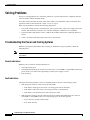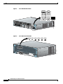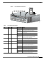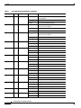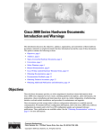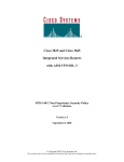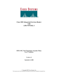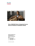
1
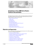
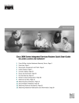
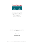
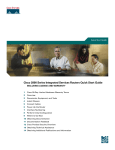
Troubleshooting Cisco 3800 Series Routers
Your Cisco 3800 series integrated services router goes through extensive testing and burn-in before
leaving the factory. If you encounter problems, use this document to help isolate problems or to eliminate
the router as the source of the problem.
This document contains the following sections:
Note
•
Solving Problems, page 2
•
LEDs, page 5
•
The show environment Command, page 9
•
Error Messages, page 10
•
Jumper Settings, page 12
•
Recovering a Lost Password, page 13
•
More Troubleshooting Help, page 13
To troubleshoot network modules, see the Cisco Network Modules Hardware Installation Guide. To
troubleshoot interface cards, see the Cisco Interface Cards Installation Guide. These documents are
available on Cisco.com.
If you cannot find the source of the problem, contact a customer service representative. For information
about obtaining technical support, see the “Obtaining Technical Assistance” section on page 12 of
“Introduction to Cisco 3800 Series Routers Hardware Documentation.” Before you call, have the
following information ready:
•
Router type and serial number (for serial number locations, see the “Product Identification” section
on page 5 of “Overview of Cisco 3800 Series Routers”)
•
Maintenance agreement or warranty information
•
Type of software and version number
•
Date you received the router
•
Brief description of the problem
•
Brief explanation of the steps taken to isolate the problem
Troubleshooting Cisco 3800 Series Routers
OL-5972-01
1
Solving Problems
Solving Problems
The key to solving problems is to isolate the problem to a specific subsystem by comparing what the
router is doing to what it should be doing.
The LEDs on the front and rear panel of the router enable you to determine router performance and
operation. LEDs are described in the “LEDs” section on page 5.
When solving problems, consider the following subsystems:
•
Power and cooling systems—External power source, power cable, router power supply and circuit
breaker, and router blower and fan. Also consider inadequate ventilation or air circulation.
•
Network modules and interface cards—LEDs on the modules and interface cards help identify a
failure.
•
Cables—External cables that connect the router to the network.
Troubleshooting the Power and Cooling Systems
Both the system power LED and the fans can help you troubleshoot a power problem. Check the
following items.
Note
The Cisco 3845 router has two system power LEDs, one for each power supply, labeled SYS PWR1 and
SYS PWR2.
Normal Indications
With the power switch on, normal indications are:
•
SYS LED steady green
•
SYS PWR LED steady green for the Cisco 3825 router, or SYS PWR1 or SYS PWR2 LED steady
green for the Cisco 3845 router (depending on which power supply is active)
•
Fans operating
Fault Indications
Check the following symptoms to locate or eliminate faults in the power and cooling systems:
•
With the power switch on, what color is the SYS LED?
– If the LED is steady green, the router is receiving power and is functional.
– If the LED is amber, the router is receiving power but is not functional.
– If the LED is off, check the power source and power cable.
•
With the power switch on, the SYS LED steady green, and the SYS PWR LED (Cisco 3825) or
SYS PWR1 or SYS PWR2 LED (Cisco 3845) steady green, do the fans operate?
– If yes, the power system is functioning.
– If no, check the fans.
Troubleshooting Cisco 3800 Series Routers
2
OL-5972-01
Solving Problems
•
With the power switch on and the SYS LED steady green, do the fans operate?
– If yes, the power system is functioning.
– If no, check the fans.
•
With the power switch on and the SYS PWR LED (Cisco 3825) or SYS PWR1 or SYS PWR2 LED
(Cisco 3845) off, do the fans operate?
– If yes, the router is receiving power. The fans are connected directly to the DC outputs of the
power supply.
– If no, check the power source and power cable.
•
Does the router shut down after being on a short time?
– Check for an environmentally induced shutdown. See the next section, “Environmental
Reporting Features.”
– Check the environmental site requirements in the “General Site Requirements” section on
page 3 of “Preinstallation Requirements and Planning for Cisco 3800 Series Routers.”
– Check for a power supply failure by inspecting the SYS PWR LED on the Cisco 3825 router,
or the SYS PWR1 or SYS PWR2 LED on the Cisco 3845 router (depending on which power
supply is active). If the LED is green, the power supply is functional.
•
Router partially boots, but LEDs do not come on.
– Check for a power supply failure by inspecting the SYS PWR LED on the Cisco 3825 router or
the SYS PWR1 LED or SYS PWR2 LED on the Cisco 3845 router (depending on which power
supply is active). If the LED is green, the power supply is functional.
– If the SYS PWR LED is not on, see the “Obtaining Technical Assistance” section on page 12
of “Introduction to Cisco 3800 Series Routers Hardware Documentation” for information about
customer service. For warranty information, see the “Cisco 90-Day Limited Hardware Warranty
Terms” section on page 10 of “Introduction to Cisco 3800 Series Routers Hardware
Documentation.”
Environmental Reporting Features
If the router is operating at an abnormally high temperature, the following message is displayed on the
console screen:
System detected OVERTEMPERATURE condition. Please resolve cooling problem immediately!
Some causes of abnormally high router temperature are:
•
Fan failure
•
Air conditioning failure in the room
•
Air blockage to cooling vents
Take steps to correct the problem. See also the “Site Environment” section on page 4 and the “Equipment
Racks” section on page 5 of “Preinstallation Requirements and Planning for Cisco 3800 Series Routers.”
Troubleshooting Cisco 3800 Series Routers
OL-5972-01
3
Solving Problems
Troubleshooting Modules, Cables, and Connections
Network problems can be caused by a module; cables or cable connections; or external devices such as
a modem, transceiver, hub, wall jack, WAN interface, or terminal. Check for the following symptoms to
help isolate the problem:
•
Network module or interface card is not recognized by the router.
– Make sure that the module or interface card is firmly seated in its slot.
– Check the LEDs on the module or interface card. For information on these LEDs, see the Cisco
Network Modules Hardware Installation Guide and the Cisco Interface Cards Installation
Guide.
– Make sure that you have a version of Cisco IOS software that supports the network module or
interface card. To determine which Cisco IOS releases support your router, network modules,
and interface cards, go to the Software Advisor at http://tools.cisco.com/Support/Fusion/. You
must have an account on Cisco.com.
•
Module or card is recognized, but interface ports do not initialize.
– Make sure that the module or card is firmly seated in its slot.
– Check external cable connections.
– Make sure that you have a version of Cisco IOS software that supports network module or
interface card. To determine which Cisco IOS releases support your router, network modules,
and interface cards, go to the Software Advisor at http://tools.cisco.com/Support/Fusion/. You
must have an account on Cisco.com.
•
Router does not boot properly, or constantly or intermittently reboots.
– Make sure that all modules are firmly seated in their slots.
– Check the router chassis or software. For information about customer service, see the
“Obtaining Technical Assistance” section on page 12 of “Introduction to Cisco 3800 Series
Routers Hardware Documentation.” For warranty information, see the “Cisco 90-Day Limited
Hardware Warranty Terms” section on page 10 of “Introduction to Cisco 3800 Series Routers
Hardware Documentation.”
•
Router boots, but the console screen is frozen.
– Check the external console connection.
– Verify that the parameters for your terminal are set as follows:
- The data rate matches the one configured for the router (9600 bps is the default)
- 8 data bits
- No parity
- 1 stop bit
•
Router powers on and boots only when a particular network module or interface card is removed.
– Check the network module or interface card. For information about customer service, see the
“Obtaining Technical Assistance” section on page 12 of “Introduction to Cisco 3800 Series
Routers Hardware Documentation.” For warranty information, see the “Cisco 90-Day Limited
Hardware Warranty Terms” section on page 10 of “Introduction to Cisco 3800 Series Routers
Hardware Documentation.”
Troubleshooting Cisco 3800 Series Routers
4
OL-5972-01
LEDs
Router powers on and boots only when a particular cable is disconnected.
•
– There may be a problem with the module, interface card, or cable. For information about
customer service, see the “Obtaining Technical Assistance” section on page 12 of “Introduction
to Cisco 3800 Series Routers Hardware Documentation.” For warranty information, see the
“Cisco 90-Day Limited Hardware Warranty Terms” section on page 10 of “Introduction to
Cisco 3800 Series Routers Hardware Documentation.”
LEDs
LEDs enable you to determine router performance and operation. Figure 1 and Figure 2 show the LEDs
on the Cisco 3825 router. Figure 3 and Figure 4 show the LEDs on the Cisco 3845 router. Each power
supply in a Cisco 3845 router also has its own LED.
For an explanation of these LEDs, see Table 1.
Figure 1
SYS
Cisco 3825 Front-Panel LEDs
ACT
SYS
PWR
AUX
PWR
RPS
AIM0
AIM1 PVDM0 PVDM1 PVDM2 PVDM3
R
FLASH
1
0
SYS
AUX
ACT
RPS
IP PWR
AIM0
AIM1
PVDM0
PVDM1
PVDM2
117780
COMPACT
PVDM3
Troubleshooting Cisco 3800 Series Routers
OL-5972-01
5
LEDs
Figure 2
Cisco 3825 Rear-Panel LEDs
CONSOLE SPD GE 1/0 LNK
AUX
NMDESW36
SPD GE 0/0 LNK
GE 0/0 SFP
35x
GE1
FastEthe
rnet Ports
10/100/100
Base-Tx 0
17x
NMESW16
35x 17x
34x 16x
33x 15x
15x
32x 14x
31x 13x
FastEthern
et Ports
30x 12x
29x 11x
18x
28x 10x
27x 9x
8x
7x
26x
8x
Ext
Pwr
25x
17
24x
Ext
Pwr
14x 6x
13x
5x
12x
4x
11x 3x
10x 2x
9x
0x
1x
8x
GE
10/100/
1000
Base-Tx
-48V
6x
23x
5x
22x
4x
21x 3x
20x
2x
19x
0x
1x
18x
GE0
10/100/
1000
Base-Tx
EN
0x
EN
0x
117782
15x 7x
-48V
Cisco 3845 Front-Panel LEDs
117781
Figure 3
Troubleshooting Cisco 3800 Series Routers
6
OL-5972-01
LEDs
Figure 4
Cisco 3845 Router Rear-Panel LEDs
GigE 0/1
SPD
LNK
SPD
LNK
PVDM 3 PVDM 2 PVDM 1 PVDM 0 AIM 1 AIM 0
CF
SFP
GigE 0/0
CONSOLE
AUX
PVDM 3
CF
SPD
PVDM 2
PVDM 1
GigE 0/1
LNK
PVDM 0
AIM 1
AIM 0
SPD
LNK
SFP
117783
GigE 0/0
Table 1
Cisco 3800 Series LED Indicators
LED
3825
3845
Color and State Meaning
SYS
Front
Front
Off
Router not receiving power
Steady green
Normal operation (power-up complete)
Blinking green Booting or in ROM monitor mode (immediately
after power-up)
ACT
SYS PWR
RPS
SYS PWR1
SYS PWR2
Front
Front
Front
—
—
Front
—
—
Front
Front
Amber
Powered but malfunctioning
Off
No packet activity
Steady or
blinking green
Packets transmitted or received on any WAN or
LAN port, or router is monitoring internal
activities (power-up completed)
Off
Router not receiving power
Steady green
Normal operation (immediately after power-up)
Off
Connected to primary power system
Steady green
Connected to redundant power system
Off
Router not receiving power, power supply 1 not
present, or power-up not completed
Steady green
Present and enabled (power-up completed)
Amber
Present and off or malfunctioning
Off
Router not receiving power, power supply 2 not
present, or power-up not completed
Steady green
Present and enabled (power-up completed)
Amber
Present and off or malfunctioning
Troubleshooting Cisco 3800 Series Routers
OL-5972-01
7
LEDs
Table 1
Cisco 3800 Series LED Indicators (continued)
LED
3825
3845
Color and State Meaning
AUX PWR
Front
—
Off
IP phone power off or not present, or power-up
not completed
Steady green
Present and enabled (power-up completed)
Amber
Powered but malfunctioning
Off
IP phone power supply 1 off or not present, or
power-up not completed
Steady green
Present and enabled (power-up completed)
Amber
Powered but malfunctioning
Off
IP phone power supply 2 off or not present, or
power-up not completed
Steady green
Present and enabled (power-up completed)
Amber
Powered but malfunctioning
Off
AIM0 not present
Green
Present and enabled
Amber
Present but malfunctioning
Off
AIM1 not present
Green
Present and enabled
Amber
Present but malfunctioning
Off
PVDM0 not present
Green
Present and enabled
Amber
Present but malfunctioning
Off
PVDM1 not present
Green
Present and enabled
Amber
Present but malfunctioning
Off
PVDM2 not present
Green
Present and enabled
Amber
Present but malfunctioning
Off
PVDM3 not present
Green
Present and enabled
Amber
Present but malfunctioning
Off
CompactFlash memory card not being accessed
Steady green
CompactFlash card being accessed; do not eject
AUX PWR1
AUX PWR2
AIM0
AIM1
PVDM0
PVDM1
PVDM2
PVDM3
CF
—
—
Front
Front
Front
Front
Front
Front
Front
Front
Front
Rear
Rear
Rear
Rear
Rear
Rear
Rear
Blinking green CompactFlash card being accessed; do not eject
SFP
Rear
GE0: Link
Rear
Rear
Rear
Off
SFP link not established
Green
SFP port active, link established
Off
No link
Green
Ethernet cable present, link established
Troubleshooting Cisco 3800 Series Routers
8
OL-5972-01
The show environment Command
Table 1
Cisco 3800 Series LED Indicators (continued)
LED
3825
3845
GE0: Speed
Rear
Rear
GE1: Link
Rear
Rear
Color and State Meaning
Blinking green Blink frequency indicates port speed
1 blink per second: 10 Mbps
2 blinks per second: 100 Mbps
3 blinks per second: 1000 Mbps
Off
No link
Green
GE1: Speed
Rear
Rear
PS1
—
Front
PS2
—
Front
Ethernet cable present, link established
Blinking green Blink frequency indicates port speed
1 blink per second: 10 Mbps
2 blinks per second: 100 Mbps
3 blinks per second: 1000 Mbps
Off
Power supply 1 not present
Steady green
Present and enabled
Amber
Present and off or malfunctioning
Off
Power supply 2 not present
Steady green
Present and enabled
Amber
Present and off or malfunctioning
The show environment Command
The show environment command can help you monitor and troubleshoot router power and ventilation
status.
This is an example of the output of the show environment command for a Cisco 3825 router with an AC
power supply and no Redundant Power System:
Router# show environment
Redundant Power System is not present.
SYS PS1 is present.
Type: AC
AUX (-48V) PS1 is absent.
Fan 1 Normal
Fan 2 Normal
Fan 3 Normal
Fan Speed is Normal
Alert settings:
Intake temperature warning: Enabled, Threshold: 50
Core temperature warning: Enabled, Threshold: 70 (CPU: 95)
Board Temperature: Normal
Internal-ambient temperature = 29, Normal
CPU temperature = 46, Normal
Intake temperature = 31, Normal
Voltage 1(3300) is Normal, Current voltage = 3316 mV
Voltage 2(5150) is Normal, Current voltage = 5210 mV
Voltage 3(2500) is Normal, Current voltage = 2525 mV
Voltage 4(1200) is Normal, Current voltage = 1191 mV
Troubleshooting Cisco 3800 Series Routers
OL-5972-01
9
Error Messages
This is an example of the output of the show environment command for a Cisco 3845 router that has
one AC power supply with IP phone power output installed:
Router# show environment
SYS PS1 is present
Fan status: Normal
Input Voltage status: Normal
DC Output Voltage status: Normal
Type: AC
Thermal status: Normal
SYS PS2 is absent
AUX (-48V) PS1 is present
AUX (-48V) PS2 is absent
Fan 1 Normal
Fan 2 Normal
Fan 3 Normal
Fan Speed is Normal
Alert settings:
Intake temperature warning: Enabled, Threshold: 50
Core temperature warning: Enabled, Threshold: 70 (CPU: 90)
Board Temperature: Normal
Internal-ambient temperature = 31, Normal
CPU temperature = 50, Normal
Intake temperature = 25, Normal
Backplane temperature = 24, Normal
Voltage 1(3300) is Normal, Current voltage = 3284 mV
Voltage 2(5150) is Normal, Current voltage = 5210 mV
Voltage 3(2500) is Normal, Current voltage = 2549 mV
Voltage 4(1200) is Normal, Current voltage = 1215 mV
Error Messages
This section describes error messages that may appear on an external console screen. (For more
information about consoles, see the “Connecting a Console or Modem” section on page 9 of
“Connecting Cables to Cisco 3800 Series Routers.”)
Cisco IOS software checks the system once every 30 seconds. If an error still exists, the error message
is displayed again; if the error has cleared, a recovery message is displayed.
Error Message System detected OVERTEMPERATURE condition. Please resolve cooling
problem immediately!
Explanation The router is operating at a temperature higher than the user-set threshold, possibly
caused by fan failure, air-conditioning failure in the room, or air blockage to cooling vents.
Recommended Action Make sure that the ambient room temperature does not exceed 40 degrees C
and that airflow to the router is not blocked. See the “Site Environment” section on page 4 and the
“Equipment Racks” section on page 5 of “Preinstallation Requirements and Planning for
Cisco 3800 Series Routers.”
If this condition persists, the power-supply thermal monitor automatically shuts down the router.
Call your Cisco technical support representative for help, if necessary.
Troubleshooting Cisco 3800 Series Routers
10
OL-5972-01
Error Messages
Error Message Fan 1|2|3 had a rotation error reported.
Explanation The specified fan is not rotating at the desired speed.
Recommended Action If this error is detected, the router system software automatically increases the
fan speed to high. If the rotation error disappears, fan speed is kept at high. If this error appears
repeatedly, there is something wrong with the fan. The error will reappear until action is taken.
Error Message Voltage 1|2|3|4 (3300 mv|5150 mv|2500 mv|1200 mv) has exceeded
recommended operating limits.
Explanation One of the internal voltage outputs is outside its operating limits.
Recommended Action System failure. See the “Obtaining Technical Assistance” section on page 12
of “Introduction to Cisco 3800 Series Routers Hardware Documentation” for information about
customer service.
Cisco 3845 Router Error Messages
The Cisco 3845 router supports two internal power supplies and returns the following error messages for
them.
Error Message System detected SYS PS 1|2 input voltage fail condition.
Explanation Power to the indicated power supply has failed.
Recommended Action Check the input power source and power cable.
Error Message System detected SYS PS 1|2 output voltage fail condition.
Explanation The indicated power supply has failed.
Recommended Action Replace the power supply. See “Installing and Upgrading Internal Components
in Cisco 3800 Series Routers.”
Error Message System detected AUX (-48V) PS 1|2 fail condition.
Explanation The indicated AC power supply with IP phone power output has failed.
Recommended Action Replace the power supply. See “Installing and Upgrading Internal Components
in Cisco 3800 Series Routers.”
Troubleshooting Cisco 3800 Series Routers
OL-5972-01
11
Jumper Settings
Error Message System detected thermal warning on SYS PS 1|2. System is close to auto
shutdown limit.
Explanation The power supply is operating at an abnormally high temperature.
Recommended Action Make sure that the ambient room temperature does not exceed 40 degrees C
and that air flow to the router is not blocked. See the “Site Environment” section on page 4 and the
“Equipment Racks” section on page 5 of “Preinstallation Requirements and Planning for
Cisco 3800 Series Routers.”
The power supply fan may have failed or be about to fail. Replace the power supply. See “Installing
and Upgrading Internal Components in Cisco 3800 Series Routers.”
If this condition persists, the power-supply thermal monitor automatically shuts down the router.
Call your Cisco technical support representative for help, if necessary.
Error Message System detected SYS PS 1|2 fan fail condition.
Explanation The fan on the indicated power supply has failed.
Recommended Action Replace the power supply. See “Installing and Upgrading Internal Components
in Cisco 3800 Series Routers.”
Error Message There is more than one failure with power system 1|2 or this power
system has been turned off.
Explanation Multiple failures have occurred in the indicated power supply. This message can also
appear if you have installed two power supplies in a Cisco 3845 router, but only one is powered on.
Recommended Action If the power supply is turned off, turn it on. If it has failed, replace it. See
“Installing and Upgrading Internal Components in Cisco 3800 Series Routers.”
Jumper Settings
If a ROM monitor failure occurs, you may need to change a jumper setting on the motherboard so the
router can boot for troubleshooting. Procedures for accessing the motherboard are described and jumper
locations are shown in “Installing and Upgrading Internal Components in Cisco 3800 Series Routers.”
You may need to set one of the following jumpers:
•
DUART DFLT—Sets the console connection data rate to 9600 regardless of user configuration
Change this setting if the console displays garbage characters. The jumper forces the data rate to a
known good value.
•
BOOT DFLT—Boots from the read-only boot image in case an upgrade is corrupted
Change this setting if the router consistently hangs or crashes after a ROM monitor upgrade.
•
WDOG DIS—Disables the watchdog timer
If you change either of the first two settings as shown, the router stays in the new configuration during
subsequent power cycles and the jumper can be removed.
Troubleshooting Cisco 3800 Series Routers
12
OL-5972-01
Recovering a Lost Password
Note
The jumpers are not needed to troubleshoot Cisco IOS problems. If the Cisco IOS software becomes
corrupted, remove the CompactFlash memory card to force the router to boot in ROM monitor mode.
Change these settings only after consulting with your service representative or Cisco technical support.
Recovering a Lost Password
You can recover a lost enable password, but an enable secret password is encrypted and is not
recoverable. If you lose an enable secret password configured on your router, you can replace it with a
new enable secret password.
For password recovery and replacement procedures, see
http://www.cisco.com/warp/public/474/index.shtml.
More Troubleshooting Help
For information about obtaining technical support, see the “Obtaining Technical Assistance” section on
page 12 of “Introduction to Cisco 3800 Series Routers Hardware Documentation.”
Troubleshooting Cisco 3800 Series Routers
OL-5972-01
13
More Troubleshooting Help
Troubleshooting Cisco 3800 Series Routers
14
OL-5972-01