1
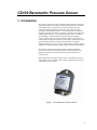
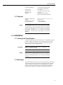
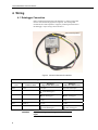
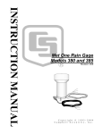
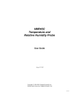
CS100
Barometric
Pressure Sensor
Instruction Manual
Issued 16.9.08
Copyright © 2002-2008 Campbell Scientific Inc.
Printed under Licence by Campbell Scientific Ltd.
CSL 533
Guarantee
This equipment is guaranteed against defects in materials and
workmanship. This guarantee applies for twelve months from date of
delivery. We will repair or replace products which prove to be defective
during the guarantee period provided they are returned to us prepaid. The
guarantee will not apply to:
•
Equipment which has been modified or altered in any way without the
written permission of Campbell Scientific
•
Batteries
•
Any product which has been subjected to misuse, neglect, acts of God
or damage in transit.
Campbell Scientific will return guaranteed equipment by surface carrier
prepaid. Campbell Scientific will not reimburse the claimant for costs
incurred in removing and/or reinstalling equipment. This guarantee and the
Company’s obligation thereunder is in lieu of all other guarantees,
expressed or implied, including those of suitability and fitness for a
particular purpose. Campbell Scientific is not liable for consequential
damage.
Please inform us before returning equipment and obtain a Repair
Reference Number whether the repair is under guarantee or not. Please
state the faults as clearly as possible, and if the product is out of the
guarantee period it should be accompanied by a purchase order.
Quotations for repairs can be given on request.
When returning equipment, the Repair Reference Number must be clearly
marked on the outside of the package.
Note that goods sent air freight are subject to Customs clearance fees
which Campbell Scientific will charge to customers. In many cases, these
charges are greater than the cost of the repair.
Campbell Scientific Ltd,
Campbell Park, 80 Hathern Road,
Shepshed, Loughborough, LE12 9GX, UK
Tel: +44 (0) 1509 601141
Fax: +44 (0) 1509 601091
Email: [email protected]
www.campbellsci.co.uk
PLEASE READ FIRST
About this manual
Please note that this manual was originally produced by Campbell Scientific Inc. primarily for the
North American market. Some spellings, weights and measures may reflect this origin.
Some useful conversion factors:
Area:
Length:
1 in2 (square inch) = 645 mm2
1 in. (inch) = 25.4 mm
1 ft (foot) = 304.8 mm
1 yard = 0.914 m
1 mile = 1.609 km
Mass:
1 oz. (ounce) = 28.35 g
1 lb (pound weight) = 0.454 kg
Pressure:
1 psi (lb/in2) = 68.95 mb
Volume:
1 UK pint = 568.3 ml
1 UK gallon = 4.546 litres
1 US gallon = 3.785 litres
In addition, while most of the information in the manual is correct for all countries, certain information
is specific to the North American market and so may not be applicable to European users.
Differences include the U.S standard external power supply details where some information (for
example the AC transformer input voltage) will not be applicable for British/European use. Please
note, however, that when a power supply adapter is ordered it will be suitable for use in your country.
Some brackets, shields and enclosure options, including wiring, are not sold as standard items in the
European market; in some cases alternatives are offered. Details of the alternatives will be covered in
separate manuals.
Recycling information
At the end of this product’s life it should not be put in commercial or domestic refuse
but sent for recycling. Any batteries contained within the product or used during the
products life should be removed from the product and also be sent to an appropriate
recycling facility.
Campbell Scientific Ltd can advise on the recycling of the equipment and in some cases
arrange collection and the correct disposal of it, although charges may apply for some
items or territories.
For further advice or support, please contact Campbell Scientific Ltd, or your local agent.
Campbell Scientific Ltd, Campbell Park, 80 Hathern Road, Shepshed, Loughborough, LE12 9GX, UK
Tel: +44 (0) 1509 601141 Fax: +44 (0) 1509 601091
Email: [email protected]
www.campbellsci.co.uk
Contents
PDF viewers note: These page numbers refer to the printed version of this document.
Use the Adobe Acrobat® bookmarks tab for links to specific sections.
1. Introduction .................................................................. 1
2. Specifications .............................................................. 2
2.1 Performance ............................................................................................. 2
2.1.1 Performance for “Standard” Range Option .................................... 2
2.1.2 Performance for “500 to 1100 mb” Range Option ......................... 2
2.1.3 Performance for “800 to 1100 mb” Range Option ......................... 2
2.2 Electrical .................................................................................................. 2
2.3 Physical .................................................................................................... 3
3. Installation .................................................................... 3
3.1 Venting and Condensation ....................................................................... 3
3.2 Mounting .................................................................................................. 3
4. Wiring ........................................................................... 4
4.1 Datalogger Connection............................................................................. 4
4.2 5-pin Screw Terminal Plug Connector ..................................................... 5
5. Programming ............................................................... 5
5.1
5.2
5.3
5.4
Conversion Factors .................................................................................. 6
Multipliers and Offsets for Different Measurement Range Options ........ 6
Program Examples ................................................................................... 7
Output Resolution .................................................................................... 9
6. Correcting Pressure to Sea Level .............................. 9
7. Maintenance and Calibration .................................... 10
Figures
1. CS100 Barometric Pressure Sensor............................................................ 1
2. CS100 as removed from the box and closeup of yellow warning label ..... 4
3. Connector Key Attached to 5-pin Screw Terminal Plug Connector .......... 5
Tables
1.
2.
3.
4.
Signal and Ground Connectors for CS100 ................................................. 4
Conversion Factors for Alternative Pressure Units .................................... 6
Multipliers and Offsets ............................................................................... 6
Wiring for Example Programs ................................................................... 7
i
CS100 Barometric Pressure Sensor
1. Introduction
The CS100 is a capacitive pressure transducer that uses the Setra's electrical
capacitor technology for barometric pressure measurements over the 600 to
1100 millibar range. The transducer’s compact and rugged polyester
housing with stainless backplate contains two closely-spaced, parallel,
electrically-isolated metallic surfaces. One of the surfaces is essentially a
diaphragm constructed of a Setra’s proprietary compound of fused glass and
ceramic (Setraceram™) or a low-hysteresis material, such as 17-4 PH SS.
The diaphragm is capable of detecting a slight change in the applied
pressure, which is then converted to an analogue voltage signal by Setra’s
custom Application Specific Integrated Circuit (ASIC). The analogue signal
generated by the barometer can be directly measured by a Campbell
Scientific datalogger, such as 21X, CR7, CR500, CR510, CR10(X), CR23X,
CR200 series, CR1000, CR3000, CR800, CR850, CR5000, and CR9000(X).
The CS100 is supplied in the triggered mode, in which the datalogger
switches 12 VDC power to the barometer before the measurement. The
datalogger then powers down the barometer after the measurements to
conserve power.
Other measurement range options such as 500 to 1100 millibar, and 800 to
1100 millibar are also available. Please contact Campbell Scientific, Inc. for
ordering these special versions.
Figure 1. CS100 Barometric Pressure Sensor
1
CS100 Barometric Pressure Sensor
2. Specifications
2.1 Performance
2.1.1 Performance for “Standard” Range Option
Measurement Range:
Operating Temperature Range:
Storage Temperature Range:
Proof Pressure:
Burst Pressure:
Humidity Range:
Media Compatibility:
Resolution:
Total Accuracy1:
Linearity:
Hysteresis:
Repeatability:
Long-term Stability:
600 mb to 1100 mb (hPa)
-40°C to +60°C (-40°F to +140°F)
-60°C to +120°C (-76°F to +248°F)
1500 mb
2000 mb
non-condensing (up to 95% RH)
non-corrosive, non-condensing air or gas
0.01 mb
±0.5 mb @ 20°C
±1.0 mb @ 0°C to +40°C
±1.5 mb @ -20°C to +50°C
±2.0 mb @ -40°C to +60°C
±0.4 mb
±0.05 mb
±0.03 mb
±0.1 mb per year
2.1.2 Performance for “500 to 1100 mb” Range Option
Measurement Range:
Total Accuracy2:
Linearity:
Hysteresis:
Repeatability:
500 to 1100 mb
±0.6 mb @ 20°C
±1.2 mb @ 0°C to +40°C
±2.0 mb @ -20°C to +50°C
±2.5 mb @ -40°C to +60°C
±0.5 mb
±0.06 mb
±0.04 mb
2.1.3 Performance for “800 to 1100 mb” Range Option
Measurement Range:
Total Accuracy3:
Linearity:
Hysteresis:
Repeatability:
800 to 1100 mb
±0.3 mb @ 20°C
±0.6 mb @ 0°C to +40°C
±1.0 mb @ -20°C to +50°C
±1.5 mb @ -40°C to +60°C
±0.25 mb
±0.03 mb
±0.02 mb
Supply Voltage:
9.5 V to 28 Vdc
2.2 Electrical
1
The root sum squared (RSS) of end point non-linearity, hysteresis, nonrepeatability and calibration uncertainty.
2
The root sum squared (RSS) of end point non-linearity, hysteresis, nonrepeatability and calibration uncertainty.
3
The root sum squared (RSS) of end point non-linearity, hysteresis, nonrepeatability and calibration uncertainty.
2
Instruction Manual
Current Consumption:
Signal Output
Warm-up Time:
Response Time:
Benefits:
3 mA nominal (operating mode)
1 µA quiescent (sleep mode)
0 to 2.5 Vdc
<1 second from shutdown mode
<100 msec
Calibration NIST traceable
Meets CE conformance standards
2.3 Physical
Dimensions (Main Box):
Weight:
Mounting Hole Centres:
Pressure Connector:
NOTE
9.1 x 6.1 x 2.5 cm (3.6” x 2.4” x 1.0”)
135 g (4.8 oz)
7.62 cm (3 inches)
1/8” ID barbed fitting
The black outer jacket of the cable is Santoprene® rubber.
This compound was chosen for its resistance to temperature
extremes, moisture, and UV degradation. However, this jacket
will support combustion in air. It is rated as slow burning
when tested according to U.L. 94 H.B. and will pass
FMVSS302. Local fire codes may preclude its use inside
building.
3. Installation
3.1 Venting and Condensation
To prevent condensation, install the sensor in an environmentally protected
enclosure, complete with desiccant, which should be changed at regular
intervals. As the sensor must detect the external ambient pressure the
enclosure must not be ‘hermetically sealed’.
CAUTION
Failure to protect the sensor from condensation may
result in permanent damage.
NOTE
If it is necessary to make a vent hole on the outer wall of an
enclosure, do not make the hole on one of the vertical side
walls, as wind blowing around it can cause transient changes
in pressure.
3.2 Mounting
The mounting holes for the sensor are one-inch-centred (three inches apart),
and will mount directly onto the holes on the backplates of the Campbell
Scientific enclosures. Mount the sensor with the pneumatic connector
pointing vertically downwards to prevent condensation collecting in the
pressure cavity, and also to ensure that water cannot enter the sensor.
3
CS100 Barometric Pressure Sensor
4. Wiring
4.1 Datalogger Connection
Before connecting the barometer to the datalogger, a yellow warning label
must be removed from the pigtails (see Figure 2). The warning label
reminds the user of the importance of properly connecting the barometer to
the datalogger. Proper wiring is shown in Table 1.
Yellow Warning Label
Figure 2. CS100 as Removed from the Box
Table 1. Signal and Ground Connectors for CS100
Wire
CS106 Terminal
Datalogger
Single-Ended Measurement
Datalogger
Differential Measurement
Blue
VOUT
S.E. Input
High Side of Diff Input
Yellow
AGND
AG (CR10(X), CR500, CR510)
(Other Dataloggers)
Low Side of Diff. Input
Black
GND
(21X, CR7, CR9000(X))
G (Other Dataloggers)
(21X, CR7, CR9000(X))
G (Other Dataloggers)
Green
EXT TRIG
Control port (use to turn power
on/off)
Control port (use to turn power
on/off)
Red
SUPPLY
12 VDC
12 VDC
Shield
Shield
G (CR10(X), CR500, CR510)
(Other Dataloggers)
G (CR10(X), CR500, CR510)
(Other Dataloggers)
WARNING
4
Improper wiring may damage the CS100 beyond
repair.
Instruction Manual
4.2 5-pin Screw Terminal Plug Connector
The datalogger connects to the CS100 via a 5-pin screw terminal plug
connector. This connector is removable and may be replaced. The
replacement connector may come with a connector key attached to it to
ensure that the connector is plugged into the CS100 right side up (see
Figure 3). When the connector is right side up, it will easily plug into the
barometer.
Figure 3. Connector Key Attached to
5-pin Screw Terminal Plug Connector
WARNING
A 5-pin screw terminal that is plugged in upside
down will damage the sensor—perhaps beyond
repair.
5. Programming
The CS100 sensor is measured using the singled-ended voltage measurement
instruction.
Atmospheric pressure changes little with time. In most weather station
applications measuring pressure once an hour is adequate.
Program Example 1 is for the dataloggers that use the CRBasic language,
such as CR200, CR800, CR850, CR1000, CR3000, CR5000, and
CR9000(X). In the example, the CR1000 measures the CS100 once an hour
in a program that runs at 1 Hz. In order to keep the CR1000 running in a
pipeline mode, the measurement instruction is placed outside the “If”
statement. The measurement is made every scan, and the measured value is
first written into a temporary variable called "CS100_temp". Once the
CS100 is turned on one minute before the hour, the CS100 starts to make the
correct pressure measurements. At the top of the hour, the correct value is
copied into the current variable called "pressure", and the sensor is turned off
immediately.
5
CS100 Barometric Pressure Sensor
In Program Example 2, the CR10X datalogger (Edlog datalogger) turns on
the CS100 one minute before the top of the hour using a control port. On the
hour the datalogger measures the CS100, and then it turns the CS100 off.
5.1 Conversion Factors
In the example programs, the pressure is reported in millibars (mb). To
report pressure in different units, multiply the measured pressure by the
appropriate conversion factor using the P37 (Z=X*F) instruction for CR500,
CR510, CR10(X), CR23X, 21X, and CR7, or by adding an expression for
CR200, C800, CR850, CR1000, CR3000, CR5000, and CR9000(X)
dataloggers. See Table 2 below for conversion factors.
Table 2. Conversion Factors for
Alternative Pressure Units
To Find
hPa
kPa
mm of Hg
in of Hg
Psi
Atm
Torr
Multiply by
1.0
0.1
0.75006
0.02953
0.0145
0.00099
0.75006
5.2 Multipliers and Offsets for Different Measurement Range
Options
For CS100 barometric pressure transducers with measurement range options
other than the standard 600 to 1100 mb option, please refer to the table
below for proper multipliers and offsets.
Table 3. Multipliers and Offsets
Range Options
600 to 1100 mb
(Standard range)
500 to 1100 mb
800 to 1100 mb
6
Multiplier
0.2
Offset
600
0.24
0.12
500
800
Instruction Manual
5.3 Program Examples
The CS100 wiring instructions for the example programs are shown in
Table 4 below.
Table 4. Wiring for Example Programs
Wire Colour
Blue
Red
Black
Yellow
Green
Clear
Description
VOUT – Pressure Signal Out
SUPPLY – 12 Vdc Power In
GND – Power Ground
AGND – Signal Ground
ETX. TRIG. – External Trigger
Shield
CR10(X)
SE6
12V
G
AG
C8
G
CR1000
SE15
12V
G
C4
G
Example 1. Sample Program for CR1000 (CRBasic) Datalogger
'CR1000 Datalogger
Public CS100_temp
Public pressure
Units pressure = mbar
DataTable (met_data,True,-1)
DataInterval (0,60,min,10)
Sample (1,pressure,IEEE4)
EndTable
BeginProg
Scan (1,sec,3,0)
‘Measurement is made every scan outside the “If” statement
VoltSe (CS100_temp,1,mV2500,15,False,200,250,0.2,600)
‘Turn on CS100 one minute before the hour
If (IfTime (59,60,min)) Then WriteIO (&b1000,&b1000)
‘Copy the correct value to a current variable called “pressure” at the top of the hour
‘Turn off CS100 after measurement
If (IfTime (0,60,min)) Then
pressure = CS100_temp
WriteIO (&b1000,&b0)
EndIf
CallTable met_data
NextScan
EndProg
7
CS100 Barometric Pressure Sensor
Example 2. Sample Program for CR10X (Edlog) Datalogger
;{CR10X}
;
*Table 1 Program
01: 1
Execution Interval (seconds)
;Turn on CS100 one minute before the hour
;
1: If time is (P92)
1: 59
Minutes (Seconds --) into a
2: 60
Interval (same units as above)
3: 48*
Set Port 8* High
;Measure CS100 at the top of the hour
;
2: If time is (P92)
1: 0
Minutes (Seconds --) into a
2: 60
Interval (same units as above)
3: 30
Then Do
3: Volt (SE) (P1)
1: 1
2: 15
3: 6
4: 1
5: 0.2
6: 600
Reps
2500 mV Fast Range
SE Channel
Loc [ P_mb ]
Multiplier
Offset
;Turn off CS100
;
4: Do (P86)
1: 58*
Set Port 8* Low
5: End (P95)
6: If time is (P92)
1: 0
Minutes (Seconds --) into a
2: 60
Interval (same units as above)
3: 10
Set Output Flag High (Flag 0)
7: Real Time (P77)
1: 0110
Day,Hour/Minute (midnight = 0000)
;Store in high resolution mode to retain 0.01mb resolution
;
8: Resolution (P78)
1: 1
High Resolution
9: Sample (P70)
1: 1
2: 1*
Reps
Loc [ P_mb
]
*Table 2 Program
02: 0.0000
Execution Interval (seconds)
8
Instruction Manual
*Table 3 Subroutines
End Program
-Input Locations1 P_mb
* Proper entries will vary with program and datalogger channel, and input location assignments.
5.4 Output Resolution
When storing the values from the CS100 to a data table or to a datalogger’s
final storage location, care must be taken to choose suitable scaling of the
reading, or to store the value with adequate resolution to avoid losing useful
resolution of the pressure measurement. The default resolution (low
resolution) for Campbell Scientific dataloggers is limited to a maximum of
four digits. Even then, the maximum digit value that can be displayed is
6999 for Edlog dataloggers, and 7999 for the CRBasic dataloggers. If you
use this option with barometric data scaled in millibars (hPa), a reading
above 799.9 mb for CRBasic dataloggers or 699.9 mb for Edlog dataloggers
will lose one digit of resolution, e.g. at 900 mb, the resolution is limited to
1 mb.
To retain 0.01 mb resolution, you either need to deduct a fixed offset from
the reading before it is stored to avoid exceeding the 799.9 for CRBasic
dataloggers or 699.9 for Edlog dataloggers threshold, or output the
barometric reading in high resolution format. This can be done by using the
IEEE4 format for the CR800, CR850, CR1000, CR3000, CR5000, and
CR9000(X) dataloggers or using the Resolution (P78) instruction for our
Edlog dataloggers. The default data output format for CR200 series
datalogger is IEEE4.
6. Correcting Pressure to Sea Level
The weather service, most airports, radio stations, and television stations
reduce the atmospheric pressure to a common reference (sea level).
Equation 1 can be used to find the difference in pressure between the sea
level and the site. That value (dP) is then added to the offset (600 mb in our
example programs) in the measurement instruction. U. S. Standard
Atmosphere and dry air were assumed when Equation 1 was derived
(Wallace, J. M. and P. V. Hobbes, 1977: Atmospheric Science: An
Introductory Survey, Academic Press,
pp. 59-61).
⎧⎪ ⎛
⎞5.25328 ⎫⎪
E
⎬
dP = 1013.25 ⎨1 − ⎜1 −
⎟
⎩⎪ ⎝ 44307.69231⎠
⎭⎪
(1)
The value dP is in millibars and the site elevation, E, is in metres. Add dP
value to the offset in the measurement instruction.
Use Equation (2) to convert feet to metres.
9
CS100 Barometric Pressure Sensor
E(m) =
E( ft )
3.281ft m
(2)
The corrections involved can be significant: e.g. at 1000mb and 20°C,
barometric pressure will decrease by 1.1mb for every 10 metre increase in
altitude.
7. Maintenance and Calibration
Since the sensor is semi-sealed, minimum maintenance is required:
1.
Visually inspect the cable connection to ensure it is clean and dry.
2.
Visually inspect the casing for damage.
3.
Ensure that the pneumatic connection and pipe are secure and
undamaged.
The external case can be cleaned with a damp, lint-free cloth and a mild
detergent solution.
Contact Campbell Scientific Ltd before returning the sensor for recalibration.
You may also return the unit directly to Setra for recalibration.
Should you lose the five terminal connector the replacement part can be
purchased from Campbell Scientific Ltd.
CAUTION
10
The CS100 is sensitive to static when the backplate is
removed. To avoid damage, take adequate anti-static
measures when handling.
CAMPBELL SCIENTIFIC COMPANIES
Campbell Scientific, Inc. (CSI)
815 West 1800 North
Logan, Utah 84321
UNITED STATES
www.campbellsci.com
[email protected]
Campbell Scientific Africa Pty. Ltd. (CSAf)
PO Box 2450
Somerset West 7129
SOUTH AFRICA
www.csafrica.co.za
[email protected]
Campbell Scientific Australia Pty. Ltd. (CSA)
PO Box 444
Thuringowa Central
QLD 4812 AUSTRALIA
www.campbellsci.com.au
[email protected]
Campbell Scientific do Brazil Ltda. (CSB)
Rua Luisa Crapsi Orsi, 15 Butantã
CEP: 005543-000 São Paulo SP BRAZIL
www.campbellsci.com.br
[email protected]
Campbell Scientific Canada Corp. (CSC)
11564 - 149th Street NW
Edmonton, Alberta T5M 1W7
CANADA
www.campbellsci.ca
[email protected]
Campbell Scientific Ltd. (CSL)
Campbell Park
80 Hathern Road
Shepshed, Loughborough LE12 9GX
UNITED KINGDOM
www.campbellsci.co.uk
[email protected]
Campbell Scientific Ltd. (France)
Miniparc du Verger - Bat. H
1, rue de Terre Neuve - Les Ulis
91967 COURTABOEUF CEDEX
FRANCE
www.campbellsci.fr
[email protected]
Campbell Scientific Spain, S. L.
Psg. Font 14, local 8
08013 Barcelona
SPAIN
www.campbellsci.es
[email protected]
Campbell Scientific Ltd. (Germany)
Fahrenheitstrasse13, D-28359 Bremen
GERMANY
www.campbellsci.de
[email protected]
Please visit www.campbellsci.com to obtain contact information for your local US or International representative.