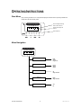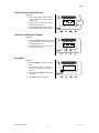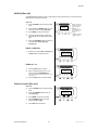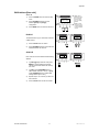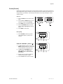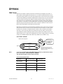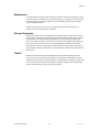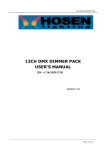
1
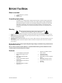
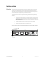
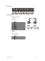
TFX-D6 Stage Dimmer™ 6 USER MANUAL th Chauvet, 3000 N 29 Ct, Hollywood, FL 33020 U.S.A (800) 762-1084 – (954) 929-1115 FAX (954) 929-5560 www.chauvetlighting.com 2005-04-20/11:20 TABLE OF CONTENT TABLE OF CONTENT ............................................................................................................................................................... 2 BEFORE YOU BEGIN ............................................................................................................................................................... 3 WHAT IS INCLUDED ...................................................................................................................................................................... 3 UNPACKING INSTRUCTIONS ........................................................................................................................................................... 3 WARNING .................................................................................................................................................................................. 3 FEATURES ................................................................................................................................................................................. 3 PRODUCT OVERVIEW................................................................................................................................................................... 4 INSTALLATION ......................................................................................................................................................................... 5 MOUNTING ................................................................................................................................................................................. 5 POWER CONNECTIONS ................................................................................................................................................................ 6 Input Power........................................................................................................................................................................ 6 Single-phase.......................................................................................................................................................................................... 6 Three-phase .......................................................................................................................................................................................... 6 Output Power..................................................................................................................................................................... 7 Control Wiring .................................................................................................................................................................... 7 Analog 0-10VDC .................................................................................................................................................................................... 7 DMX512 ................................................................................................................................................................................................ 7 OPERATING INSTRUCTIONS.................................................................................................................................................. 8 START MENU ............................................................................................................................................................................. 8 MENU NAVIGATION ...................................................................................................................................................................... 8 Temporary Intensity Per Channel ..................................................................................................................................... 9 Temporary Intensity All Channels ..................................................................................................................................... 9 Setup Menu ....................................................................................................................................................................... 9 DMX Fail [Dmx fail].......................................................................................................................................................... 10 Hold, Analog ........................................................................................................................................................................................ 10 Prog.01-12........................................................................................................................................................................................... 10 Phase Correction [Pha corr]............................................................................................................................................ 10 DMX Address [Dmx addr] ............................................................................................................................................... 11 Block ................................................................................................................................................................................................... 11 Single .................................................................................................................................................................................................. 11 Preheat [Preheat] ............................................................................................................................................................ 12 All [All] ................................................................................................................................................................................................. 12 Single Channel [Chan [?]]..................................................................................................................................................................... 12 Dimmer Curve [Curve]..................................................................................................................................................... 13 Dimmer Curve Explained ................................................................................................................................................ 13 APPENDIX................................................................................................................................................................................ 14 DMX PRIMER ........................................................................................................................................................................... 14 Fixture Linking ..................................................................................................................................................................................... 14 MAINTENANCE .......................................................................................................................................................................... 15 RETURNS PROCEDURE .............................................................................................................................................................. 15 CLAIMS ................................................................................................................................................................................... 15 TECHNICAL SPECIFICATIONS ....................................................................................................................................................... 16 TFX-D6 User Manual 2 2005-04-20/11:20 BEFORE YOU BEGIN What is included 1 x Stage Dimmer™ 6 (TFX-D6) Manual Warranty Card Unpacking Instructions Immediately upon receiving a fixture, carefully unpack the carton, check the contents to ensure that all parts are present, and have been received in good condition. Notify the shipper immediately and retain packing material for inspection if any parts appear damaged from shipping or the carton itself shows signs of mishandling. Save the carton and all packing materials. In the event that a fixture must be returned to the factory, it is important that the fixture be returned in the original factory box and packing. Warning Please read these instructions carefully, which includes important information about the installation, usage and maintenance? Please keep this User Guide for future consultation. If you sell the unit to another user, be sure that they also receive this instruction booklet. Always make sure that you are connecting to the proper voltage and that the line voltage you are connecting to is not higher than that stated on decal or rear panel of the fixture. This product is intended for indoor use only! To prevent risk of fire or shock, do not expose fixture to rain or moisture. Make sure there are no flammable materials close to the unit while operating. The unit must be installed in a location with adequate ventilation, at least 50cm from adjacent surfaces. Be sure that no ventilation slots are blocked. Because Dimmer packs operate at potentially lethal high voltages, installation wiring should be done by qualified persons only! Do not connect chassis Ground to Neutral, or operate without chassis ground, otherwise the user could be exposed to potentially lethal voltages. Features 6-channel DMX-512 dimmer/switch DMX-512 and Analog 0~10v DC control Each channel individually DMX addressable 12 built-in beat-activated programs (stand-alone) 10 Amp magnetic circuit breaker in each channel Set preheat voltage to individual channel or all TFX-D6 User Manual 3 Dimmer curve selection; square, switch or linear AC phase correction Power failure memory Digital display and menu navigation buttons DMX signal loss failover function Thermal switch and short circuit protection Fan cooled 2005-04-20/11:20 Introduction Product Overview Forced air cooling Not visible LCD Display 10A Circuit breaker DMX Signal Indicator MENU Button UP Button Standard 19” EIA rack mountable DOWN Button ESC Button Rear cover panel TFX-D6 Front panel I/O Panel TFX-D6 User Manual 4 BUTTON FUNCTION MENU Access the set-up and menu functions UP Scroll menu functions or increase values DOWN Scroll menu functions or decrease values ESC Go back one menu or leave menu system 2005-04-20/11:20 INSTALLATION Mounting The TFX-D6 dimmer packs are designed to be mounted in a standard 19” EIA rack using the two mounting holes on each flange/(ears). The two mounting flanges are designed for securing the dimmer pack to the front rack mounting rails. It is highly recommended that you add support to the rear of the dimmer pack, especially in touring or road case environments. The TFX-D6 depends on forced air cooling and the following guidelines should be applied during installation: 1. The rack enclosure must maintain a 4 inch minimum clearance on the entire left side of the dimmer rack. The rack enclosure must not be sealed, and must maintain an air exhaust clearance area of at least 20 square inches per installed pack to allow air flow back to the ambient room. 2. The intake manifold on the front of the dimmer pack can never be blocked. 3. Ambient room temperature must never exceed 104°F/50°C Failure to adhere to proper and safe installation guidelines may result in a VOID of warranty! 17 8” 19“ TFX-D6 3 ½” Rack ears TFX-D6 User Manual 5 2005-04-20/11:20 Operating Instructions Power Connections Warning! Make certain that power is removed from the circuits before you begin installation of the dimmer. Consult your local electrical codes to determine the proper wire type and wiring methods for your regional installation. Input Power SI NG L E-PHASE 1 phase, 3 wire 120/240 VAC, 60 Amps, 50~60Hz L1 L2 E N L L3 N N N E E T HREE-PHASE 3 phase, 4 wire 120/240 VAC, 20 Amps per phase, 50~60Hz TFX-D6 User Manual L1 L2 L3 L1 L2 L3 E N N N N 6 E E 2005-04-20/11:20 Output Power Control Wiring AN AL O G 0-10VDC Input: 8-pin DIN Output: 8-pin DIN Pin Signal Ch1 Signal ( - ) Ch2 Signal ( - ) Ch3 Signal ( - ) GND Ground Ch4 Signal ( - ) Ch5 Signal ( - ) Ch6 Signal ( - ) +DC 20V Signal ( + ) GND GND DMX512 Input: 3-pin XLR (male) Output: 3-pin XLR (female) Pin Signal 1 DGND 2 DATA ( - ) 3 DATA ( + ) TFX-D6 User Manual 7 2005-04-20/11:20 OPERATING INSTRUCTIONS Start Menu Upon powering the dimmer, the LCD panel will display the software version presently installed and shortly after, will enter standby mode. First line displays dimming levels of each channel. 1 Second line displays the channel. 1 2 3 4 5 6 Channel buttons Menu Navigation 1 1 2 3 4 5 6 Dmx fail Curve Preheat DMX addr Pha corr TFX-D6 User Manual 8 Hold Analog Prog.01-12 Linear Switch Square All Single Channel Block Single Channel Yes No 2005-04-20/11:20 Appendix Temporary Intensity Per Channel Action 1) Press a channel button to select desired channel output. Every press will change intensity once. 2) Hold the button for 2 seconds to change channel intensity rapidly. 3) Press the ESC button to switch between increasing or decreasing channel intensity. 1 1 2 3 4 5 6 1 1 2 3 4 5 6 Channel buttons Temporary Intensity All Channels Action Setup Menu 1) Press the UP/DOWN buttons to set desired intensity for all channel outputs. Every press will change intensity once. 2) Hold the button for 2 seconds to change channel intensity rapidly. Action 1) Press the MENU button to enter the setup menu. 2) There are 5 menu items to choose from; Dmx fail, Curve, Preheat, Dmx addr, and Pha corr. 3) Press the UP and DOWN buttons to scroll menu items. 4) Press ESC to exit the setup menu. TFX-D6 User Manual 9 Dmx fail 2005-04-20/11:20 Appendix DMX Fail [Dmx fail] The DMX Fail feature allows the user to select how the dimmer will behave if you were to loose the DMX controller’s signal to the dimmer. Action 1) Press the MENU button to enter the setup menu. 2) Press the UP and DOWN buttons to scroll menu items until you reach [Dmx fail]. 3) Press MENU to enter the sub-menu. 4) If it were running the built-in scene 08 it would display as per the illustration on the right. 5) Press the UP/DOWN buttons to select one of the following; [Hold], [Analog], [Prog.01-12]. Dmx fail Prog08 Hold – The dimmer will hold the last dmx signal received. Analog – The dimmer will revert to the Analog input signal. ProgXX - Will start internal programs 112. HO L D, AN AL O G 1) Whether you choose Hold or Analog press the ESC button to confirm and exit. Dmx fail (Hold) or (Analog) PRO G . 01-12 1) Press the ESC button to confirm. 2) Select a chasing speed from 0.1 to 20 seconds using the UP/DOWN button. Speed 00.3s (Hold the UP/DOWN buttons for two seconds to change speed quickly.) 3) Press the ESC button to confirm setting. Phase Correction [Pha corr] Action 1) Press the MENU button to enter the setup menu. 2) Press the UP/DOWN buttons until you reach [Pha corr]. 3) Press MENU to enter the sub-menu. 4) Press UP/DOWN buttons to choose between [Yes] and [No]. 5) Press ESC button to activate. TFX-D6 User Manual 10 Pha corr (Yes) or (No) 2005-04-20/11:20 Appendix DMX Address [Dmx addr] Action 1) 2) 3) Press the MENU button to enter the setup menu. Dmx addr (Block) or (Single) Press UP/DOWN buttons to choose between [Block] and [Single] configuration. Block – Block addressing refers to 6 consecutive channels using only one starting address. Single – Allows the user to select a starting address for each individual channel. Press MENU button to enter the sub-menu. BL O CK The dimmer will occupy 6 consecutive channels Dmx addr Block Start [001] Chan [1] [001] Chan [1] [001] of DMX control. 1) Press the ESC button to confirm. 2) Press UP/DOWN buttons to select the start address between 001 and 512. SI NG L E Each channel can have a different DMX starting address. 1) In [Chan[1]]/Single Channel mode press MENU to change between the dimmer channel and its’ start address as noted by the cursor. 2) In [Chan], press UP/DOWN buttons to select dimmer channels 1 thru 6. In [001], press UP/DOWN buttons to select DMX starting address [001 to 512]. 3) Repeat steps 1 thru 2 to until you have set all 6 channels. 4) Press the ESC button to exit and confirm. TFX-D6 User Manual 11 2005-04-20/11:20 Appendix Preheat [Preheat] Enabling the preheat function will protect your lamps against cold starts. Upon powering the dimmer a trickle voltage will be output to the lamps, not enough for the lamp to be visible by the human eye, but enough to warm up the filament. This will help increase the life of your lamps. Usually 6% of 100% output is sufficient. Action 1) Press the MENU button to enter the setup menu. 2) Press the UP and DOWN buttons to scroll menu items until you reach [Preheat]. 3) Press MENU button to enter the sub-menu. 4) Press the UP/DOWN buttons to choose between [All] and [Chan]/Single Channel mode. 5) Press MENU to select mode. Preheat All Chan [1] [000%] AL L [ Al l ] 1) Press UP/DOWN to select the preheat value between [000%] – [050%] for all channels. All [005%] SI NG L E CHANNEL [Ch an [?]] 1) In [Chan [1]]/Single Channel mode press MENU to change between the channel and its’ start address as noted by the cursor. 2) In [Chan], press UP/DOWN buttons to select channels 1~6. In [001], press UP/DOWN buttons to select percentage [000%-050%]. 3) Repeat steps 1 thru 2 for any additional channel you would like to change. 4) Press the ESC button to exit and confirm. TFX-D6 User Manual 12 Chan [1] [050%] 2005-04-20/11:20 Dimmer Curve [Curve] Action 1) Press the MENU button to enter the setup menu. 2) Press the UP and DOWN buttons to scroll menu items until you reach [Curve]. 3) Press the MENU button to enter the submenu. 4) Press UP/DOWN buttons to select from Single or All. Press MENU to confirm. 5) If choosing Single read next step, other wise skip to step 7. 6) Single: You can change the dimmer curve of each channel 7) a. Press UP/DOWN buttons to select a channel Chan[ 1 ] ~ Chan[ 6 ], Press MENU b. Press UP/DOWN buttons to select Square, Switch & Linear, Press MENU c. Skip to step 8 to end. Single / All Channel [ ? ] Linear/Square/Switch All: Applies the dimmer curve to all channels a. 8) Curve Channel [ 2 ] Switch Press UP/DOWN buttons to select Square, Switch & Linear, Press MENU Press ESC button to exit and confirm. Dimmer Curve Explained Square Curve: Dimmer scale and output wattage are closer in relationship. It is a more precise method of varying wattage output. LEGEND Linear Curve: Preferred method for lighting programmers. See explanation below. Square law Linear Switch Curve: The dimmer will not dim but simply provide full voltage output when commanded above 50%. 100% 90% LIGHT OUTPUT 80% The human eye is most sensitive to the intensity of light at levels below 25% of its 100% brightness. Using the Linear dimming curve provides lighting designers greater control of light intensity levels that are most visible by everyone by expanding the range of control using the slider. TFX-D6 User Manual 70% 60% Greatest control of levels below 25% using the slider 50% 40% 30% Least control of levels below 25% using the slider 20% 10% 0% 13 50% DIMMER LEVEL 100% 2005-04-20/11:20 APPENDIX DMX Primer There are 512 channels in a DMX-512 connection. Channels may be assigned in any manner. A fixture capable of receiving DMX 512 will require one or a number of sequential channels. The user must assign a starting address on the fixture that indicates the first channel reserved in the controller. There are many different types of DMX controllable fixtures and they all may vary in the total number of channels required. Choosing a start address should be planned in advance. Channels should never overlap. If they do, this will result in erratic operation of the fixtures whose starting address is set incorrectly. You can however, control multiple fixtures of the same type using the same starting address as long as the intended result is that of unison movement or operation. In other words, the fixtures will be slaved together and all respond exactly the same. DMX fixtures are designed to receive data through a serial Daisy Chain. A Daisy Chain connection is where the DATA OUT of one fixture connects to the DATA IN of the next fixture. The order in which the fixtures are connected is not important and has no effect on how a controller communicates to each fixture. Use an order that provides for the easiest and most direct cabling. Connect fixtures using shielded two conductor twisted pair cable with three pin XLR male to female connectors. The shield connection is pin 1, while pin 2 is Data Negative (S-) and pin 3 is Data positive (S+). CHAUVET carries 3-pin XLR DMX compliant cables, DMX-10 (33’), DMX-4.5 (15’) and DMX-1.5 (5’) F I XT URE LI NKI NG DMX connector configuration 1 3 2 COMMON INPUT Note! 1 3 2 1 3 2 DMX + Resistance 120 ohm 1/4w between pin 2 (DMX -) and pin 3 (DMX +) of the last fixture. OUTPUT DMX - Termination reduces signal errors and to avoid signal transmission problems and interference, it is always advisable to connect a DMX signal terminator. If you use a controller with a 5 pin DMX output connector, you will need to use a 5 pin to 3 pin adapter. CHAUVET Model No: DMX5M. The chart below details a proper cable conversion: 3 PIN TO 5 PIN CONVERSION CHART CONDUCTOR 3 Pin Female (output) 5 Pin Male (Input) GROUND/SHIELD Pin 1 Pin 1 DATA ( - )SIGNAL Pin 2 Pin 2 DATA ( + ) SIGNAL Pin 3 Pin 3 DO NOT USE Do not use DO NOT USE Do not use TFX-D6 User Manual 14 2005-04-20/11:20 Appendix Maintenance To maintain optimum performance and minimize wear fixtures should be cleaned frequently. Usage and environment are contributing factors in determining frequency. As a general rule, fixtures should be cleaned at least twice a month. Dust build can cause overheating. Be sure to power off fixture before conducting maintenance. Unplug fixture from power. Use a vacuum or air compressor and a soft brush to remove dust collected on external vents and internal components. Returns Procedure Returned merchandise must be sent prepaid and in the original packing, call tags will not be issued. Package must be clearly labeled with a Return Merchandise Authorization Number (RA #). Products returned without an RA # will be refused. Call CHAUVET and request RA # prior to shipping the fixture. Be prepared to provide the model number, serial number and a brief description of the cause for the return. Be sure to properly pack fixture, any shipping damage resulting from inadequate packaging is the customer’s responsibility. CHAUVET reserves the right to use its own discretion to repair or replace product(s). As a suggestion, proper UPS packing or double-boxing is always a safe method to use. Claims Damage incurred in shipping is the responsibility of the shipper; therefore the damage must be reported to the carrier upon receipt of merchandise. It is the customer's responsibility to notify and submit claims with the shipper in the event that a fixture is damaged due to shipping. Any other claim for items such as missing component/part, damage not related to shipping, and concealed damage, must be made within seven (7) days of receiving merchandise. TFX-D6 User Manual 15 2005-04-20/11:20 Appendix Technical Specifications WEIGHT & DIMENSIONS Length .............................................................................................................................. 452 mm (17.8 in) Width ................................................................................................................................... 483 mm (19 in) Height ................................................................................................................................... 89 mm (3.5 in) Weight ................................................................................................................................ 9.98 Kg (22 lbs) INPUT POWER Switch-selectable power setting (on-board PCB)........................................... 115V 60 Hz or 230V 50 Hz Single-phase input ...........................................................3 wire + GD, 120/230 VAC, 60 Amps, 50-60Hz Three-phase input ..........................................................4 wire + GD, 120/230 VAC, 60 Amps, 50-60Hz OUTPUT CAPACITY 120VAC, 6-channels..........................................................................1200 Watts per channel @ 120VAC 230VAC, 6-channels..........................................................................2300 Watts per channel @ 230VAC OUTPUT PANEL .......................................................................................................................... Hard-wired terminal blocks OVERLOAD PROTECTION ..................................................................................... 10 Amp Fast Acting Circuit Breakers per Channel CONTROL & PROGRAMMING Data input....................................................................................................locking 3-pin XLR male socket Data output ............................................................................................. locking 3-pin XLR female socket Data pin configuration................................................................................. pin 1 shield, pin 2 (-), pin 3 (+) Protocols ...........................................................................................................................DMX-512 USITT DMX Channels........................................................................................................................................... 6 Analog .................................................................................................................... 6 channels of 0-10VDC ORDERING INFORMATION Stage Dimmer™ 6 .......................................................................................................................... TFX-D6 TFX-D6 User Manual 16 2005-04-20/11:20