1
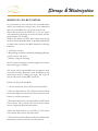
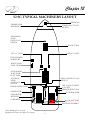
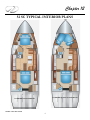
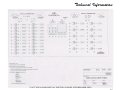
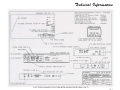
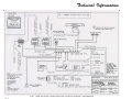
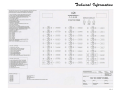
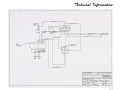
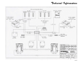
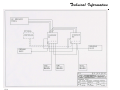
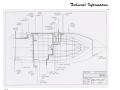
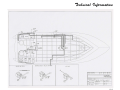
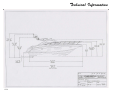
52 SC OWNER’S MANUAL
REGAL #526043
4-2013
Table Of Contents
1 INTRODUCTION
Regal Owner’s Manual
Owner’s Information Packet
General Information
Regal Marine Limited Warranty
1-4
1-4
1-5
1-12
2 SAFETY ON BOARD
Safety Labels
General Boating Safety
Required Safety Equipment
Fire Extinguishers
Visual Distress Signals
Sound Protecting Devices
Radio Communications
Navigation Lights
MarineSanitation Devices
EBIRB
Life Rafts
U.S.C.G Minimum Equipment Requirements
Exhaust & Carbon Dioxide
Boating & Alcohol
BoatingAccidents
Water Sports
Weather & Water Conditions
2-1
2-2
2-4
2-6
2-7
2-10
2-10
2-10
2-10
2-12
2-13
2-13
2-14
2-16
2-18
2-20
2-21
3 RULES OF THE ROAD
Navigation Rules Defined
Navigation Rules
Bridge Clearance
3-1
3-1
3-8
4 SYSTEMS
Fuel
Electrical
Generator
Air Conditioner
Fresh Water
Waste Water
Dingy
Trim Tabs
Sun Roof
Windlass
Entertainment
Electronics
4-2
4-11
4-56
4-61
4-66
4-76
4-84
4-89
4-91
4-92
4-97
4-106
Table Of Contents
5 ENGINE & CONTROLS
Overview
Instrumentation
IPS Engines
Controls
Joysticks
Drive/Propellers
5-1
5-6
5-8
5-14
5-18
5-22
6 VESSEL OPERATION
Getting Underway
Starting & Stopping
Fenders
Dock Line Basics
Knots
Anchoring
Towing
Admiralty Law
Emergencies
Environmental Awareness
6-1
6-4
6-5
6-6
6-8
6-9
6-10
6-10
6-11
6-13
7 AUXILIARY EQUIPMENT OPERATION
Interior Equipment Component
Carbon Monoxide Detector
Door-Companionway
Grey Water System
Hatches
Lighting-Cabin
Monitor-Water/Waste
Portlights
Range/Stove
Refrigerator
Salon Furniture-Dinette
Seat-Helm
TV-LCD Monitor Precautions
Vacuum Cleaner
Washer-Dryer Combo
7-3
7-4
7-5
7-6
7-7
7-10
7-11
7-12
7-13
7-15
7-16
7-17
7-18
7-20
Chapter 10
DIESEL GENERATOR (WESTERBEKE)
Selected yachts feature Westerbeke diesel generators. If
equipped, the generator must be decommissioned for
storage in freezing climates. Your Regal dealer or marine
professional has special training along with the necessary
parts for winterizing your generator.
If tackling the procedure yourself, here are the basics
of winterizing the generator. Refer to your generator
operator’s manual for further information. The vessel
must be in the water for the procedures below. Remove
any sound shield enclosure as equipped.
Change the fuel filter elements on the engine and bleed the
fuel system as needed. Start the engine and let it run for
5-10 minutes to make sure no air is left in the fuel system.
Check for any leaks that may have been created in the fuel
system during this servicing, correcting them as needed.
Operating the engine 5-10 minutes will help allow
movement of the treated fuel through the injection
equipment on the engine.
Close the through hull seacock. Remove the raw water
intake hose from the fitting. Place the end of this hose into
a five gallon bucket of clean fresh water. Before starting
the engine check the zinc anode found in the primary
heat exchanger on the engine and clean or replace it as
required and also clean any zinc debris from inside the
heat exchanger where the zinc anode is located. Clean the
raw water strainer.
Start the engine and allow the raw water pump to draw the
fresh water through the system. When the bucket is empty
stop the engine and refill the bucket with an antifreeze
solution slightly stronger than needed for winter freeze
protection in your area.
Start the engine and allow all of this mixture to be drawn
through the raw water system. Once the bucket is empty,
stop the engine. This antifreeze mixture should protect the
raw water circuit from freezing during the winter lay-up,
as well as providing corrosion protection.
Remove the impeller from your raw water pump (some
antifreeze mixture will accompany it, so catch it in a
bucket). Examine the bucket. Get a replacement if needed
and a cover gasket. Do not replace the impeller (into the
pump) until recommissioning, but replace the cover and
gasket.
A 50-50 solution of antifreeze and distilled water is
recommended for use in the fresh water cooling system at
all times. This solution may require a higher concentration
depending on the area’s winter climate. Check the solution
to make sure the antifreeze protection is sufficient.
If you need to add antifreeze, drain an appropriate amount
from the engine block and add a more concentrated
measure. Start the engine to ensure a complete circulation
and mixture of the antifreeze concentration thoughout
the cooling system. Then recheck the antifreeze solution’s
strength with a bulb type checker.
With the engine warm, drain all the engine oil from the oil
sump. Remove and replace the oil filter and fill the sump
with new oil. Use the correct grade of oil according to the
engine lubricating oil section of your generator operator
manual. Run the engine and check for proper oil pressure
and make sure it is leak free.
Do not leave the old engine oil in the crankcase over
the lay-up period. The old oil and combustion products
combine to produce harmful chemicals which can reduce
the life of your engine’s internal parts.
Top off your fuel tanks off with number 2 diesel fuel. Fuel
additives such as BIOBOR and STABIL should be added
at this time to control algae and condition the fuel. Care
should be taken that the additives used are compatible
with the primary fuel filter/water seperator used in the
system. Change the element in your primary fuel filter/
water seperator and clean the seperator sediment bowl.
6
Storage & Winterization
MODELS W/ SEA KEY SYSTEM
If you winterize or store your boat for an extended time,
and it is not connected to shore power, it is recommended
that you put the MSU into off season power mode.
The power mode puts the MSU into a very low power
state, minimizing the drain on the boat’s battery and the
internal battery of the MSU.
While in this mode, the MSU will continue monotoring
the float switch and SOS button, responding immediately
to either alarm. However, the MSU disables the following
functions:
1. GeoFence violation
2. Responding to website commands, including polling the
vessel’s location and status
3. Battery voltage monotoring
Note: If someone attemps to start the engine, power switch
alarm will trigger if enabled.
Off season can be commanded from the operator mode
or from the Sea Key Response Center. Swithching on the
main battery and/or starting the engine will stop Off
Season and restore normal MSU functions.
Enable Off Season Power Mode
1. On the main menu, select Off Season Power Mode.
2. Press the Enter button. The Off Season Power Mode
screen will display the instructions. Press the down arrow
button to read the instructions.
3. Press the Enter button. to put the SeaKey in Offf Season
Power Mode. The Confirm Off Season Power Mode
screen is displayed. Read the instructions.
4.Press the Enter button to put SeaKey in Off Season
Power Mode and return to the main menu.
5. The Off Season Power Mode is fully activated when the
main battery switch is turned to the Off position.
7
Chapter 10
SEA KEY-GLOBAL POSITIONING SYSTEM
8
Storage & Winterization
TELEVISION:
The television manufacturer recommends that the unit be
removed from the vessel in freezing climates. To remove
the flat screen do the following:
1. Pull out the power plug from the rear of the
television.
2. Unscrew the antenna cable.
3. While someone holds the flat screen, remove the screws
that hold the television to the bracket.
4. Remove the television and store at room temperature.
9
Chapter 10
WASHER/DRYER
10
Storage & Winterization
WASTE/TOILET SYSTEM:
WATER SYSTEM-FRESH
1. Pump out waste holding tank, flush the tank with fresh
water and pump out again.
1. Turn on the fresh water pump switch.
2. With non-toxic propylene glycol antifreeze in the fresh
water tank, operate head until antifreeze flows into bowl
of head. Allow time between flushes for the vacuum to
build up.
3. Operate macerator until antifreeze has a steady
flow coming from the discharge fitting. Pour non-toxic
propylene glycol antifreeze solution in head and flush
head as needed to produce enough flow to winterize the
macerator.
4. Leave at least 2 gallons of non-toxic propylene glycol
antifreeze solution in the holding tank during storage.
NOTICE
USE A SPECIAL NON-TOXIC ANTIFREEZE
IN THE FRESH WATER & WASTE SYSTEM
WHICH IS AVAILABLE AT RV AND
MARINE DEALERS.
DO NOT USE AN AUTOMOTIVE
TYPE ANTIFREEZE.
IT CAN BE HIGHLY
POISONOUS AND CORROSIVE.
2. Open all faucets including transom shower and allow
tank to empty.
3. Drain the water heater; shut off water pump switch.
4. Mix nontoxic antifreeze with water in accordance with
the manufacturer’s recommendations.
5. Pour solution into the fresh water tank.
6. Turn on fresh water pump switch.
7. Open each cold water faucet one by one beginning
with the one furthest away from the tank and purge the
system until a steady stream flows from the faucet. Then
close the faucet.
8. Repeat step 7 for hot water faucets.
9. Shut off water pump switch.
10. Pour a quart of antifreeze into shower drain. Run
the shower pump until a steady stream flows from the
discharge fitting.
11. Leave at least 2 gallons of antifreeze solution in the
holding tank during storage.
11
Chapter 10
Notes
12
Glossary & Index
Following is a brief list of nautical terms useful in everyday Bitter end: the end of a line also the end of an anchor
boating experiences and communications. For more line
detailed glossaries of nautical terminology we recommend
you check your local library, the internet or a marine store Bow: the front, or forward part of the boat
for boating books.
Bulkhead: the vertical partition or wall of a boat
GLOSSARY
Cast off: to let go or release
Abeam: at right angles to the fore and aft line and off
the boat
Chine: the line fore and aft formed by the intersection of
the side and bottom of the boat
Aboard: on or in the boat
Chock: deck fitting used to secure or guide anchor or tie
Above: the part of the boat on a bavin vessel which is lines
above the interor of the boat
Cleat: deck fitting with protruding arms around which
Aft, After: aft is the boat section toward the stern or back lines are secured
of the boat
Cockpit: the seating space used to accomodate
Admidships: toward the center of the boat from either passengers
side to side or rear to front
Cuddy: a small cabin in the fore part of the boat
Beam: the width of a boat at its widest part
Deck: the open flooring surface on which crew and
passengers walk
Bilge: the lower interior of the hull of the boat
1
Chapter 11
Draft: the depth from the waterline of the boat to the Lee: the side opposite that from which the wind is blowing:
lowest part of the boat, which indicates how much water the side sheltered from the wind
is required to float the boat
Leeward: the direction toward which the wind is
blowing
Fathom: a measurement of depth; one fathom equals
six feet
PFD: personal floatation device; required for each person
aboard
Fender: a cushion hung from the side of a boat to prevent
it from rubbing against a dock or against other boats
Port: the left side of the boat when facing forward (an
easy way to remember the difference between “port”
Fend off: to push off to avoid sharp contact with dock and “starboard” is that both “port” and “left” have four
or other vessel
letters)
Shank: the main body of an anchor
Fore: the part of the boat toward the bow or front
Sheer: the curve of the boat’s deck from fore to aft when
Freeboard: the height of the top side from the waterline seen from the side
to the deck at its shortest point. (The distance from the
sheer or gunwale to the water)
Starboard: the right side of the boat when facing
forward
Galley: cooking area
Stern: the aft end of the boat
Gunwale: rail or upper edge of the side of the boat
Stern drive: an inboard/outboard (IO)unit
Hatch: an opening in the deck to provide access below
Stringer: strengthening integral unit fastened from fore to
aft inside the hull and fiberglass encapsulated for added
strength: much like the skeleton system of our body
Head: toilet
Hull: the part of the hull from the deck down
Top off: to fill up a tank
IPS: inboard propulsion system by Volvo
Transom: the vertical part of the stern.
Keel: the lowest point of a boat
Trim: the boat’s balance when properly loaded
Knots: a measurement of speed indicating nautical miles
Wake: the path of a boat left astern in the water
per hour
2
Glossary & Index
A
AC Current
AC Panel
Accidents
Accident Reporting
Air Conditioner
Alcohol Myths & Facts
Antennae
Anchoring
Autopilot
B
Batteries
Battery Charger
Battery Parallel Switch
Battery Switches
Bilge-Engine Compartment
Bilge Pump
Bottom Paint
Breakers
Breaker Panel (Helm)
Breast Lines
Bridge Clearance
C
CD Player
Cabinet Care
Cord Cable System
4-41
9-10
4-49
2-18
2-19
4-61
8-24
9-2
2-18
7-24
8-27
6-9
4-111
Camera Monitoring System
Canvas
Carbon Monoxide
Carbon Monoxide Detector
Cardiopulmonary Resuscitation
Carpet-Cockpit
Carpet-Interior
Compass
4-12
8-28
4-20
8-29
9-7
4-26
8-31
4-17
8-3
7-25
8-32
7-26
8-3
9-8
4-19
4-29
4-33
4-34
4-35
6-6
3-8
Cool Cockpit Air Conditioning
Corian®
Controls
D
DVD/CD Disc Care
DC Panel
Dealer Responsibilities
Decommissioning
Depth Sounder
Diagnostic Charts (Troubleshooting)
Diesel Fuel Filter
Dingy
Direct Current (DC)
Distress Signals
Diver’s Flag
Docking
Dock Lines
Dockside Power (Shorepower)
Dockside Water Inlet
Door (Cabin Entry/Companionway)
Door (Transom)
Drain Plug
3
4-102
8-4
4-42
8-34
4-116
7-27
8-34
7-124
8-5
2-14
7-3
8-35
6-11
8-6
8-6
7-28
8-35
7-29
8-9
5-14
4-102
4-33
1-10
10-2
7-113
9-1
4-8
4-84
4-33
9-11
2-7
2-20
6-8
6-6
4-41
4-68
7-4
8-36
7-30
6-1
Chapter 11
E
ELCI
EVC Display
Electrical
Electronics
Auto Pilot
Depth Sounder
E- Series Plotter
Radar
Satellite TV
Sirius Marine Weather
Sirius Satellite Radio
Engine
Entertainment
Environmental Awareness
Exhaust
F
Fabrics-Interior
Fenders
Fiberglass Maintenance
Fire Extinguishers
Fires
First Aid
Float Plan
Flooring
Fresh Water System
Fuel System
Furniture (Salon)
G
4-46
5-6
4-11
Technical
4-106
8-36
9-12
4-111
4-113
4-107
4-109
4-101
4-114
8-58
9-26
7-49
Garbage Discharge
Gauges/Switch Panels
Gelcoat Maintenance
General Boating Safety
Generator
Getting Underway
Glossary
Granite
Ground Fault Outlet (GFCI)
H
Hardtop
Hardtop Enclosure
Hatches
Heater-Hot Water
5-8
8-65
4-97
10-2
6-14
2-14
High Water Alarm
HIN
Horn
8-10
6-5
8-11
2-6
7-32
8-38
6-11
6-11
1-7
8-13
4-66
5-29
9-15
4-2
6-3
8-39
7-15
Hull/Deck
Hypothermia
I
IPod Dock
Ignition Switch
Index
Instruments (Gauges)
International Distress Signals
Isolator-Galvanic
K
Knots
4
2-12
8-14
8-11
2-2
4-56
7-34
9-18
8-40
6-1
11-1
8-15
4-52
8-50
7-35
7-36
7-6
4-74
7-38
8-51
7-39
8-52
1-5
2-10
8-53
8-17
6-12
7-100
9-23
4-27
11-3
5-6
8-14
9-22
2-9
4-47
9-16
6-8
Glossary & Index
L
Lights
R
2-11
7-7
Range
Refrigerator
M
Maintaining PFD’S
Markers-For Slings
Mayday
Microwave
Minimum Required Equipment
Monitor Panel
Mooring
N
Navigation Aids
Navigation Lights
Navigation Rules
O
Oil Change System
Overboard Discharge Pump
Overloading
Owner Packet
Owner Responsibilities
P
Personal Flotation Devices
Plastics
Plumbing Connectors
Portlights
Pre-departure questionaire
Propellers
Propulsion
Pressure Pump-Fresh Water
Refrigerator Icemaker Combo
Registration Information
Remote Control
Right-Of-Way
2-6
7-40
2-10
8-17
2-13
7-10
6-6
3-5
2-11
3-1
7-41
8-54
4-79
7-45
8-57
2-3
1-4
1-11
2-4
8-18
8-55
7-11
6-1
5-22
5-1
7-46
8-56
5
7-12
8-18
7-13
9-24
9-25
1-10
5-14
3-1
Chapter 11
S
Safety Labels
Seacocks
SeaKey
Seat- Helm
Shorepower
Shower-Transom
Shower Sump Pump
Slings-(Lifting)
Sound Producing Devices
Specifications
Spotlight
Spring Line
Strainer
Stainless Steel
Stains
Stern Line
Steering
Stereo/CD Player/i Pod
Stereo Remote
Sunpad/Chaise Lounge
Sunroof
Swim Ladder
Swim Platform
Switches (DC)
Switches (AC)
T
2-1
4-79
8-62
8-57
7-16
4-41
7-48
4-74
8-58
12-22
2-10
Technical
7-51
6-6
4-65
8-16
8-19
6-6
5-14
4-103
8-59
4-103
7-52
4-91
7-54
2-20
7-55
4-34
4-49
Tachometer
Technical Drawings
Technical Information
Television
Toilet-Vacuum Style
Towing
Transformer-Isolation
Trim Tabs
Troubleshooting
U
Underwater Lighting
Upholstery
V
VHF
Vacuum Cleaner System
Ventilation System
Vessel Information Sheet
Visual Distress Signals
W
Washer/Dryer
Waste Vent Line Filter
Waste Water
Windlass
6
5-11
9-27
12-11
12-1
7-17
8-60
4-77
8-22
8-63
9-30
6-10
8-61
4-89
8-61
9-1
7-56
8-21
4-117
8-37
7-18
8-64
4-5
1-5
2-7
7-20
8-88
4-78
4-76
4-92
8-90
9-36
Glossary & Index
Z
Zipper Care
8-5
7
Chapter 11
Notes
8
Technical
A portion of the technical drawings found in this chapter
are actual product drawings from the Regal factory. These
drawings should be of special interest in mechanical and
electrical troubleshooting. The equipment in the drawings
is discussed in the various sections of this manual.
Understanding specific systems and related drawings will
go a long ways in solving problems on your vessel.
Note that drawings found here may apply to earlier or
later yachts. A portion are marked accordingly. Sometimes
knowing the brand of a component or system can
help identify the correct drawing along with using the
particular schematic from the vendor file found in the
owner’s information packet.
Again, seek professional help as needed.
TECHNICAL INFORMATION
Note that all product specifications,
models, standard, optional equipment,
systems, along with the technical
information is subject to change
without notice.
For more information contact your
nearest authorized Regal dealer.
For the location of your nearest
authorized dealer call 407-851-4360
or you can contact Regal through the internet at : www.
regalboats.com. Your Regal dealer has received special
factory training on the entire product line and his services
should be employed to solve more technical problems.
1
Chapter 12
52 SC TYPICAL MACHINERY LAYOUT
WINDLASS
FRESHWATER
WASHDOWN
WINDLASS CUT-OUT
SWITCH
FWD. BILGE
PUMP
FWD. FLOAT
SWITCH
WASTE TANK
AFT A/C UNIT
FWD. A/C UNIT
FWD. SHOWER
SUMP PUMP
WASTE TANK
VENT FILTER
AFT SHOWER
SUMP PUMP
FUEL TANK
AFT BILGE
PUMP
AFT FLOAT
SWITCH
HIGH WATER FLOAT
SWITCH
OPT. COOL COCKPIT
A/C UNIT
FRESH WATER TANK
FRESH WATER TANK
GENERATOR
WATER HEATER
GENERATOR
MUFFLER
CORD REEL
HOUSE BATTERY
ENGINE BATTERIES
*Note-Drawing Not To Scale
Equipment Location Is Subject To Change
2
Technical Information
52 SC TYPICAL LABEL LOCATIONS
SLING
POWER SWITCH
AT BOW ANCHOR WINDLASS
MUST BE IN OFF POSITION
WHEN NOT IN USE.
SLING
*Note-Drawing Not To Scale
Labels & Location Subject To Change
3
Chapter 12
52 SC TYPICAL INTERIOR PLANS
FORWARD QUEEN W/TWIN BUNK
FORWARD VIP STATEROOM
*NOTE: NOT TO SCALE
4
Technical Information
52 SC TYPICAL MAIN SHIP’S AC ELECTRICAL PANEL WITH BREAKER SIZES
12-5
Technical Information
52 SC TYPICAL BOSE 321 SYSTEM WITH SATELLITE OPTION (1 OF 2)
12-6
Technical Information
52 SC TYPICAL BOSE 321 SYSTEM WITH SATELLITE OPTION (2 OF 2)
12-7
Technical Information
12-8
52 SC TYPICAL DUAL CHARTPLOTTER WITH AUTOPILOT AND RADAR
Technical Information
52 SC TYPICAL MAIN SHIP’S DC ELECTRICAL PANEL WITH BREAKER SIZES
12-9
Technical Information
12-10
52 SC TYPICAL BATTERY MANAGEMENT PANEL
Technical Information
52 SC TYPICAL COCKPIT SWITCH PANEL 1OF 2
12-11
Technical Information
12-12
52 SC TYPICAL PORT COCKPIT SWITCH PANEL 2 OF 2
Technical Information
52 SC TYPICAL WINDSHIELD WIPER WIRING
12-13
Technical Information
12-14
52 SC TYPICAL BATTERY CIRCUIT WIRING
Technical Information
52 SC TYPICAL DC NEGATIVE (GROUND) WIRING CIRCUIT
12-15
Technical Information
12-16
52 SC TYPICAL DUAL BATTERY CHARGER WIRING
Technical Information
52 SC TYPICAL BATTERY CHARGER SYSTEM CONNECTIONS
12-17
Technical Information
12-18
52 SC TYPICAL FRESH WATER PLUMBING LAYOUT
Technical Information
52 SC TYPICAL WASTE WATER PLUMBING LAYOUT
12-19
Technical Information
12-20
52 SC TYPICAL OVERALL BOAT DIMENSIONS
Technical Information
52 SC TYPICAL WATERLINE DIMENSIONS
12-21
Technical Information
WING
147 INCHES
332 INCHES
NOTICE TO BOAT OWNER/LIFT OPERATOR:
BEFORE LIFTING BOAT PLACE FENDER OR BLOCK BETWEEN STRAP AND
HULL JUST UNDER THE SWIM PLATFORM SIDE WING (BOTH PORT AND
STBD.) TO RELIEVE STRAP PRESSURE ON WING WHEN LIFTING BOAT.
WHEN FENDER POSITIONED CORRECTLY STRAP SHALL NOT PUT PRESSURE
ON SIDE WING WHEN FULL WEIGHT IS APPLIED.
12-22
52 SC TYPICAL BOAT LIFTING LOCATIONS (IPS DRIVES)
Technical Information
NOTICE
BOAT OWNER-LIFT OPERATOR
Before lifting boat place a fendor
or block between strap and hull
just under the swim platform side
wing (Both port and starboard) to
relieve strap pressure on wing when
lifting boat. When fender or block
is positioned correctly strap will not
put pressure on side wing when full
weight is applied.
FAILURE TO FOLLOW THE ABOVE INSTRUCTIONS
MAY CAUSE FIBERGLASS DAMAGE WHICH IS
NOT COVERED UNDER THE REGAL LIMITED
WARRANTY.
BEFORE LIFTING THE VESSEL SEE PAGE 22
OF THIS MANUALS TECHNICAL DRAWING
SECTION. FOR FURTHER INFORMATION CALL
YOUR REGAL YACHT DEALER OR THE REGAL
FACTORY.
12-23