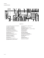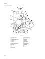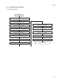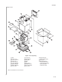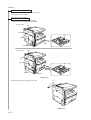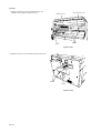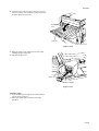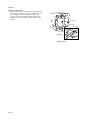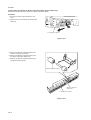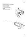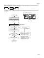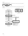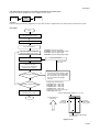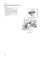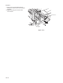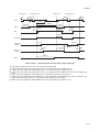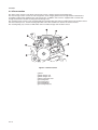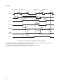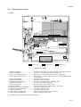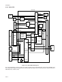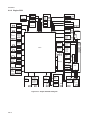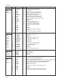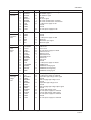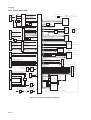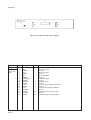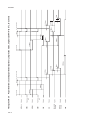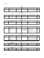
1
Service Manual
Copy
CD 1116
CD 1120
Rev. 1
Service Manual
Copy
DC 2116
DC 2120
Rev. 1
CAUTION
Danger of explosion if battery is incorrectly replaced. Replace only with the same or equivalent
type recommended by the manufacturer. Dispose of used batteries according to the
manufacturer’s instructions.
CAUTION
Double-pole/neutral fusing.
This page is intentionally left blank.
Safety precautions
This booklet provides safety warnings and precautions for our service personnel to ensure the safety of
their customers, their machines as well as themselves during maintenance activities. Service personnel
are advised to read this booklet carefully to familiarize themselves with the warnings and precautions
described here before engaging in maintenance activities.
Safety warnings and precautions
Various symbols are used to protect our service personnel and customers from physical danger and
to prevent damage to their property. These symbols are described below:
DANGER: High risk of serious bodily injury or death may result from insufficient attention to or incorrect
compliance with warning messages using this symbol.
WARNING:Serious bodily injury or death may result from insufficient attention to or incorrect compliance
with warning messages using this symbol.
CAUTION: Bodily injury or damage to property may result from insufficient attention to or incorrect
compliance with warning messages using this symbol.
Symbols
The triangle ( ) symbol indicates a warning including danger and caution. The specific point
of attention is shown inside the symbol.
General warning.
Warning of risk of electric shock.
Warning of high temperature.
indicates a prohibited action. The specific prohibition is shown inside the symbol.
General prohibited action.
Disassembly prohibited.
indicates that action is required. The specific action required is shown inside the symbol.
General action required.
Remove the power plug from the wall outlet.
Always ground the copier.
1. Installation Precautions
WARNING
• Do not use a power supply with a voltage other than that specified. Avoid multiple connections to
one outlet: they may cause fire or electric shock. When using an extension cable, always check
that it is adequate for the rated current. ............................................................................................
• Connect the ground wire to a suitable grounding point. Not grounding the copier may cause fire or
electric shock. Connecting the earth wire to an object not approved for the purpose may cause
explosion or electric shock. Never connect the ground cable to any of the following: gas pipes,
lightning rods, ground cables for telephone lines and water pipes or faucets not approved by the
proper authorities. .............................................................................................................................
CAUTION:
• Do not place the copier on an infirm or angled surface: the copier may tip over, causing injury. .....
• Do not install the copier in a humid or dusty place. This may cause fire or electric shock. ..............
• Do not install the copier near a radiator, heater, other heat source or near flammable material.
This may cause fire. ..........................................................................................................................
• Allow sufficient space around the copier to allow the ventilation grills to keep the machine as cool
as possible. Insufficient ventilation may cause heat buildup and poor copying performance. ..........
• Always handle the machine by the correct locations when moving it. ..............................................
• Always use anti-toppling and locking devices on copiers so equipped. Failure to do this may
cause the copier to move unexpectedly or topple, leading to injury..................................................
• Avoid inhaling toner or developer excessively. Protect the eyes. If toner or developer is
accidentally ingested, drink a lot of water to dilute it in the stomach and obtain medical attention
immediately. If it gets into the eyes, rinse immediately with copious amounts of water and obtain
medical attention. ..............................................................................................................................
• Advice customers that they must always follow the safety warnings and precautions in the copier’s
instruction handbook. ........................................................................................................................
2. Precautions for Maintenance
WARNING
• Always remove the power plug from the wall outlet before starting machine disassembly. ..............
• Always follow the procedures for maintenance described in the service manual and other related
brochures. .........................................................................................................................................
• Under no circumstances attempt to bypass or disable safety features including safety
mechanisms and protective circuits. .................................................................................................
• Always use parts having the correct specifications. ..........................................................................
• Always use the thermostat or thermal fuse specified in the service manual or other related
brochure when replacing them. Using a piece of wire, for example, could lead to fire or other
serious accident. ...............................................................................................................................
• When the service manual or other serious brochure specifies a distance or gap for installation of a
part, always use the correct scale and measure carefully. ...............................................................
• Always check that the copier is correctly connected to an outlet with a ground connection. ............
• Check that the power cable covering is free of damage. Check that the power plug is dust-free. If
it is dirty, clean it to remove the risk of fire or electric shock. ............................................................
• Never attempt to disassemble the optical unit in machines using lasers. Leaking laser light may
damage eyesight. ..............................................................................................................................
• Handle the charger sections with care. They are charged to high potentials and may cause
electric shock if handled improperly. .................................................................................................
CAUTION
• Wear safe clothing. If wearing loose clothing or accessories such as ties, make sure they are
safely secured so they will not be caught in rotating sections...........................................................
• Use utmost caution when working on a powered machine. Keep away from chains and belts. .......
• Handle the fixing section with care to avoid burns as it can be extremely hot. .................................
• Check that the fixing unit thermistor, heat and press rollers are clean. Dirt on them can cause
abnormally high temperatures. ..........................................................................................................
• Do not remove the ozone filter, if any, from the copier except for routine replacement. ...................
• Do not pull on the AC power cord or connector wires on high-voltage components when removing
them; always hold the plug itself. ......................................................................................................
• Do not route the power cable where it may be stood on or trapped. If necessary, protect it with a
cable cover or other appropriate item. ..............................................................................................
• Treat the ends of the wire carefully when installing a new charger wire to avoid electric leaks........
• Remove toner completely from electronic components. ...................................................................
• Run wire harnesses carefully so that wires will not be trapped or damaged. ...................................
• After maintenance, always check that all the parts, screws, connectors and wires that were
removed, have been refitted correctly. Special attention should be paid to any forgotten
connector, trapped wire and missing screws. ..................................................................................
• Check that all the caution labels that should be present on the machine according to the
instruction handbook are clean and not peeling. Replace with new ones if necessary. ...................
• Handle greases and solvents with care by following the instructions below: ....................................
· Use only a small amount of solvent at a time, being careful not to spill. Wipe spills off completely.
· Ventilate the room well while using grease or solvents.
· Allow applied solvents to evaporate completely before refitting the covers or turning the main
switch on.
· Always wash hands afterwards.
• Never dispose of toner or toner bottles in fire. Toner may cause sparks when exposed directly to
fire in a furnace, etc...........................................................................................................................
• Should smoke be seen coming from the copier, remove the power plug from the wall outlet
immediately. ......................................................................................................................................
3. Miscellaneous
WARNING
• Never attempt to heat the drum or expose it to any organic solvents such as alcohol, other than
the specified refiner; it may generate toxic gas. ................................................................................
2DA/2DB-1
CONTENTS
1-1 Specifications
1-1-1 Specifications .......................................................................................................................................
1-1-2 Parts names and their functions ...........................................................................................................
(1) MFP ................................................................................................................................................
(2) Operation panel ..............................................................................................................................
1-1-3 Machine cross section ..........................................................................................................................
1-1-4 Drive system ........................................................................................................................................
1-1-1
1-1-3
1-1-3
1-1-4
1-1-5
1-1-6
1-2 Handling Precautions
1-2-1 Drum .................................................................................................................................................... 1-2-1
1-2-2 Toner .................................................................................................................................................... 1-2-1
1-2-3 Installation environment ....................................................................................................................... 1-2-2
1-3 Installation
1-3-1 Unpacking and installation ................................................................................................................... 1-3-1
(1) Installation procedure ..................................................................................................................... 1-3-1
1-3-2 Setting initial copy modes .................................................................................................................... 1-3-6
1-3-3 Installing the paper feeder (option) ...................................................................................................... 1-3-7
1-3-4 Installing the DP (option) ...................................................................................................................... 1-3-9
1-3-5 Installing the duplex unit (option) ....................................................................................................... 1-3-13
1-3-6 Installing the drawer heater (option) ................................................................................................... 1-3-16
1-3-7 Installing the key counter (option) ...................................................................................................... 1-3-19
1-3-8 Installing the finisher (option) ............................................................................................................. 1-3-22
1-3-9 Installing the job separator (option) .................................................................................................... 1-3-30
1-3-10 Installing the fax system (option) ........................................................................................................ 1-3-35
1-3-11 Installing the scan system (option) ..................................................................................................... 1-3-43
1-3-12 Installing the hard disk (option) .......................................................................................................... 1-3-45
1-4 Maintenance Mode
1-4-1 Maintenance mode ............................................................................................................................... 1-4-1
(1) Executing a maintenance item ....................................................................................................... 1-4-1
(2) Maintenance modes item list .......................................................................................................... 1-4-2
(3) Contents of maintenance mode items ............................................................................................ 1-4-5
1-4-2 Management mode ............................................................................................................................ 1-4-54
(1) Using the management mode ...................................................................................................... 1-4-54
(2) Setting the job accounting ............................................................................................................ 1-4-55
(3) Copy default ................................................................................................................................. 1-4-56
(4) Machine default ............................................................................................................................ 1-4-58
(5) Bypass setting .............................................................................................................................. 1-4-60
(6) Checking the total counter and printing out the counter report ..................................................... 1-4-60
(7) Status report print out ................................................................................................................... 1-4-60
(8) Language selection function ......................................................................................................... 1-4-60
1-5 Troubleshooting
1-5-1 Paper misfeed detection ...................................................................................................................... 1-5-1
(1) Paper misfeed indication ................................................................................................................ 1-5-1
(2) Paper misfeed detection conditions ................................................................................................ 1-5-2
(3) Paper misfeeds ............................................................................................................................... 1-5-7
1-1-1
1-5-2 Self-diagnosis .....................................................................................................................................
1-5-17
(1) Self-diagnostic function ................................................................................................................ 1-5-17
(2) Self-diagnostic codes ................................................................................................................... 1-5-18
1-5-3 Image formation problems ................................................................................................................. 1-5-26
(1) No image appears (entirely white). ............................................................................................... 1-5-27
(2) No image appears (entirely black). ............................................................................................... 1-5-27
(3) Image is too light. ......................................................................................................................... 1-5-28
2DA/2DB-1
(4) Background is visible. ...................................................................................................................
(5) A white line appears longitudinally. ..............................................................................................
(6) A black line appears longitudinally. ..............................................................................................
(7) A black line appears laterally. .......................................................................................................
(8) One side of the copy image is darker than the other. ...................................................................
(9) Black dots appear on the image. ..................................................................................................
(10) Image is blurred. ...........................................................................................................................
(11) The leading edge of the image is consistently misaligned with the original. ................................
(12) The leading edge of the image is sporadically misaligned with the original. ................................
(13) Paper creases. .............................................................................................................................
(14) Offset occurs. ...............................................................................................................................
(15) Image is partly missing. ................................................................................................................
(16) Fixing is poor. ...............................................................................................................................
(17) Image is out of focus. ...................................................................................................................
(18) Image center does not align with the original center. ...................................................................
1-5-4 Electrical problems .............................................................................................................................
(1) The machine does not operate when the power switch is turned on. ...........................................
(2) The drive motor does not operate (C2000). .................................................................................
(3) The registration motor does not operate. .....................................................................................
(4) The exit motor does not operate. ..................................................................................................
(5) The scanner motor does not operate. ..........................................................................................
(6) Cooling fan motor 1 does not operate. .........................................................................................
(7) Cooling fan motor 2 does not operate. .........................................................................................
(8) Cooling fan motor 3 does not operate. .........................................................................................
(9) The drawer drive motor* does not operate. ..................................................................................
(10) The paper feed clutch does not operate. ......................................................................................
(11) The bypass paper feed clutch does not operate. .........................................................................
(12) The drawer paper feed clutch* does not operate. ........................................................................
(13) The cleaning lamp does not turn on. ............................................................................................
(14) The exposure lamp does not turn on. ...........................................................................................
(15) The exposure lamp does not turn off. ...........................................................................................
(16) The fixing heater does not turn on (C6000). .................................................................................
(17) The fixing heater does not turn off. ...............................................................................................
(18) Main charging is not performed. ...................................................................................................
(19) Transfer charging is not performed. .............................................................................................
(20) No developing bias is output. .......................................................................................................
(21) The original size is not detected. ..................................................................................................
(22) The original size is not detected correctly. ...................................................................................
(23) The message requesting paper to be loaded is shown when paper is present in the drawer 1. ..
(24) The message requesting paper to be loaded is shown when paper is present in the drawer 2*.
(25) The size of paper in the drawer 1 is not displayed correctly. ........................................................
(26) The size of paper in the drawer 2* is not displayed correctly. ......................................................
(27) A paper jam in the paper feed, paper conveying or fixing section is indicated when
the power switch is turned on. ......................................................................................................
(28) The message requesting covers to be closed is displayed when the front cover and
left cover are closed. ....................................................................................................................
(29) Others. ..........................................................................................................................................
1-5-5 Mechanical problems .........................................................................................................................
(1) No primary paper feed. .................................................................................................................
(2) No secondary paper feed. ............................................................................................................
(3) Skewed paper feed. ......................................................................................................................
(4) The scanner does not travel. ........................................................................................................
1-1-2
(5) Multiple sheets of paper are fed at one time. .................................................................................
(6) Paper jams. ..................................................................................................................................
(7) Toner drops on the paper conveying path. ...................................................................................
(8) Abnormal noise is heard. ..............................................................................................................
1-5-28
1-5-28
1-5-29
1-5-29
1-5-29
1-5-30
1-5-30
1-5-30
1-5-31
1-5-31
1-5-31
1-5-32
1-5-32
1-5-32
1-5-33
1-5-34
1-5-34
1-5-34
1-5-34
1-5-34
1-5-35
1-5-35
1-5-35
1-5-35
1-5-35
1-5-35
1-5-35
1-5-36
1-5-36
1-5-36
1-5-36
1-5-36
1-5-36
1-5-36
1-5-37
1-5-37
1-5-37
1-5-37
1-5-37
1-5-37
1-5-37
1-5-37
1-5-38
1-5-38
1-5-38
1-5-39
1-5-39
1-5-39
1-5-39
1-5-39
1-5-39
1-5-39
1-5-40
1-5-40
2DA/2DB-1
1-6 Assembly and Disassembly
1-6-1 Precautions for assembly and disassembly ......................................................................................... 1-6-1
(1) Precautions ..................................................................................................................................... 1-6-1
(2) Running a maintenance item .......................................................................................................... 1-6-2
1-6-2 Paper feed section ............................................................................................................................... 1-6-3
(1) Detaching and refitting the separation pulley ................................................................................. 1-6-3
(2) Detaching and refitting the forwarding pulley and paper feed pulley .............................................. 1-6-5
(3) Detaching and refitting the feed roller (20 ppm model only) ........................................................... 1-6-7
(4) Detaching and refitting the drawer separation pulley (20 ppm model only) .................................... 1-6-8
(5) Detaching and refitting the drawer forwarding pulley and drawer paper feed pulley
(20 ppm model only) ....................................................................................................................... 1-6-9
(6) Detaching and refitting the paper conveying unit ......................................................................... 1-6-11
(7) Detaching and refitting the bypass paper feed pulley and bypass separation pad ...................... 1-6-13
(8) Detaching and refitting the registration left roller .......................................................................... 1-6-15
(9) Detaching and refitting the registration cleaner ............................................................................ 1-6-15
(10) Adjustment after roller and clutch replacement ............................................................................ 1-6-16
(10-1) Adjusting the leading edge registration of image printing .................................................... 1-6-16
(10-2) Adjusting the leading edge registration for memory image printing ..................................... 1-6-17
(10-3) Adjusting the center line of image printing ........................................................................... 1-6-18
(10-4) Adjusting the trailing edge margin of image printing ............................................................ 1-6-19
(10-5) Adjusting the margins for printing ........................................................................................ 1-6-20
(10-6) Adjusting the amount of slack in the paper .......................................................................... 1-6-21
1-6-3 Optical section .................................................................................................................................... 1-6-22
(1) Detaching and refitting the exposure lamp ................................................................................... 1-6-22
(2) Detaching and refitting the scanner wires .................................................................................... 1-6-23
(2-1) Detaching the scanner wires ............................................................................................... 1-6-23
(2-2) Fitting the scanner wires ...................................................................................................... 1-6-25
(3) Detaching and refitting the ISU (reference) .................................................................................. 1-6-28
(4) Detaching and refitting the laser scanner unit .............................................................................. 1-6-29
(5) Adjusting the longitudinal squareness (reference) ....................................................................... 1-6-32
(6) Adjusting magnification of the scanner in the main scanning direction ........................................ 1-6-33
(7) Adjusting magnification of the scanner in the auxiliary scanning direction ................................... 1-6-34
(8) Adjusting the scanner leading edge registration ........................................................................... 1-6-35
(9) Adjusting the scanner center line ................................................................................................. 1-6-36
(10) Adjusting the margins for scanning an original on the contact glass ............................................ 1-6-37
1-6-4 Drum section ....................................................................................................................................... 1-6-38
(1) Detaching and refitting the drum unit ............................................................................................ 1-6-38
(2) Detaching and refitting the drum separation claws ....................................................................... 1-6-39
(3) Detaching and refitting the main charger unit ............................................................................... 1-6-40
1-6-5 Developing section .............................................................................................................................. 1-6-41
(1) Detaching and refitting the developing unit .................................................................................. 1-6-41
1-6-6 Transfer section .................................................................................................................................. 1-6-42
(1) Detaching and refitting the transfer roller ..................................................................................... 1-6-42
1-6-7 Fixing section ...................................................................................................................................... 1-6-43
(1) Detaching and refitting the fixing unit ........................................................................................... 1-6-43
(2) Detaching and refitting the press roller ......................................................................................... 1-6-45
(3) Detaching and refitting the fixing heater M and S ......................................................................... 1-6-46
(4) Detaching and refitting the heat roller separation claws ............................................................... 1-6-47
(5) Detaching and refitting the heat roller ........................................................................................... 1-6-48
(6) Detaching and refitting the fixing thermostat ................................................................................ 1-6-49
(7) Detaching and refitting the fixing thermistor ................................................................................. 1-6-49
(8) Adjusting the fixing unit height (adjusting lateral squareness) ...................................................... 1-6-50
1-1-3
1-7 Requirements on PCB Replacement
1-7-1
1-7-2
1-7-3
1-7-4
Upgrading the firmware on the main PCB ............................................................................................
Upgrading the printer board firmware ..................................................................................................
Adjustment-free variable resisters (VR) ...............................................................................................
Remarks on engine PCB or main PCB replacement ...........................................................................
1-7-1
1-7-2
1-7-3
1-7-3
2DA/2DB-1
2-1 Mechanical construction
2-1-1 Paper feed section ............................................................................................................................... 2-1-1
2-1-2 Optical section ...................................................................................................................................... 2-1-4
(1) Original scanning ............................................................................................................................ 2-1-5
(2) Image printing ................................................................................................................................. 2-1-6
2-1-3 Drum section ........................................................................................................................................ 2-1-8
2-1-4 Developing section ............................................................................................................................. 2-1-10
(1) Formation of magnetic brush ........................................................................................................ 2-1-11
(2) Single component developing system .......................................................................................... 2-1-12
2-1-5 Transfer and separation sections ....................................................................................................... 2-1-13
2-1-6 Fixing section ..................................................................................................................................... 2-1-15
(1) Fixing temperature system ........................................................................................................... 2-1-16
(2) Fixing temperature control based on ambient temperature .......................................................... 2-1-16
2-1-7 Exit and switchback sections ............................................................................................................. 2-1-17
2-1-8 Duplex section .................................................................................................................................... 2-1-18
(1) Paper conveying operation in duplex copying .............................................................................. 2-1-19
2-2 Electrical Parts Layout
2-2-1 Electrical parts layout ...........................................................................................................................
(1) PCBs ..............................................................................................................................................
(2) Switches and sensors .....................................................................................................................
(3) Motors .............................................................................................................................................
(4) Other electrical components ...........................................................................................................
2-2-1
2-2-1
2-2-2
2-2-4
2-2-5
2-3 Operation of the PCBs
2-3-1
2-3-2
2-3-3
2-3-4
2-3-5
2-3-6
Power source PCB ............................................................................................................................... 2-3-1
Main PCB ............................................................................................................................................. 2-3-4
Engine PCB .......................................................................................................................................... 2-3-8
Printer board PCB .............................................................................................................................. 2-3-14
Operation unit PCB ............................................................................................................................ 2-3-18
CCD PCB ........................................................................................................................................... 2-3-21
2-4 Appendixes
Timing chart No. 1 .......................................................................................................................................... 2-4-1
Timing chart No. 2 .......................................................................................................................................... 2-4-2
Timing chart No. 3 .......................................................................................................................................... 2-4-3
Timing chart No. 4 .......................................................................................................................................... 2-4-4
Chart of image adjustment procedures .......................................................................................................... 2-4-5
Maintenance parts list .................................................................................................................................... 2-4-8
Periodic maintenance procedures .................................................................................................................. 2-4-9
General wiring diagram ................................................................................................................................ 2-4-11
1-1-4
2DA/2DB
1-1-1 Specifications
Type ............................................... Desktop
Copying system .............................. Indirect electrostatic system
Originals ......................................... Sheets, books and 3-dimensional objects (Maximum original size: A3/11" × 17")
Original feed system ...................... Fixed
Copy paper ..................................... Paper weights
Drawer: 60 – 105 g/m2
Bypass table: 45 – 160 g/m2
Paper type
Drawer: Plain paper, recycled paper and colored paper
Bypass table: Plain paper, recycled paper, thin paper, thick paper and colored paper
Copying sizes ................................. Maximum: A3/11" × 17"
Minimum: A6R /51/2" × 81/2"
Magnification ratios ........................ Manual mode: 25 – 200%, 1% increments
Copy speed .................................... At 100% magnification in copy mode:
16 ppm model
20 ppm model
A4: 16 copies/min.
A4: 20 copies/min.
A4R: 13 copies/min.
A4R: 13 copies/min.
A3: 8 copies/min.
A3: 10 copies/min.
A5R: 10 copies/min.
A5R: 10 copies/min.
A6R: 10 copies/min.
A6R: 10 copies/min.
B5: 16 copies/min.
B5: 20 copies/min.
B5R: 13 copies/min.
B5R: 13 copies/min.
B4 (257 × 364 mm): 8 copies/min.
B4 (257 × 364 mm): 11 copies/min.
11" × 81/2": 16 copies/min.
11" × 81/2": 20 copies/min.
1
8 /2" × 11": 13 copies/min.
81/2" × 11": 13 copies/min.
11" × 17": 8 copies/min.
11" × 17": 10 copies/min.
81/2" × 14": 8 copies/min.
81/2" × 14": 11 copies/min.
First copy time ................................ 5.9 s or less (A4/11" × 81/2")
Warm-up time ................................. Less then 20 s (room temperature 23°C/73.4°F, 50% RH)
Time for recovery from low power mode: 10 s
Time for recovery from sleep mode: 20 s
Paper feed system ......................... Automatic feed
Capacity:
Drawers: 300 sheets (80 g/m2)
100 sheets (90 – 105 g/m2)
Manual feed
Capacity:
Bypass: 50 sheets (A4/11" × 81/2" or less)
25 sheets (A3, B4, 11" × 17", 81/2" × 14")
Paper ejection system .................... In-machine ejection (face down)
Capacity: 250 sheets (80 g/m2)
Continuous copying ........................ 1 – 999 sheets
Photoconductor .............................. OPC (drum diameter 30 mm)
Charging system ............................ Single positive corona charging
Recording system .......................... Semiconductor laser
Developing system ......................... Single component developing system
Toner: magnetism toner
Toner replenishing: automatic from a toner container
Transfer system ............................. Transfer roller
Separation system ......................... Curvature separation and separation electrode
Fixing system ................................. Heat roller
Heat source: halogen heaters (120 V specifications:main 550 W, sub 400W/ 220-240
V specifications: main 590 W, sub 430 W)
Control temperature: 170°C/338°F (180°C/356°F on and after 6th sheet)
Abnormally high temperature protection device: 180°C/356°F thermostat
Fixing pressure: 44.1 N
Charge erasing system .................. Exposure by cleaning lamp
Cleaning system ............................. Cleaning blade
Scanning system ............................ Flat bed scanning by CCD image sensor
Bitmap memory .............................. 35 MB (standard)
Image storage memory .................. 29 MB (standard)
1-1-1
2DA/2DB-1
Additional memory ......................... 16 MB, 32 MB, 64 MB and 128 MB
Resolution ...................................... 600 × 600 dpi
Light source .................................... Inert gas lamp
Dimensions .................................... 16 ppm model: 574 (W) × 593 (D) × 545 (H) mm
225/8" (W) × 233/8" (D) × 217/16" (H)
20 ppm model: 574 (W) × 593 (D) × 650 (H) mm
225/8" (W) × 233/8" (D) × 259/16" (H)
Weight ............................................ 16 ppm model: Approx. 42 kg/92.4 lbs
20 ppm model: Approx. 49 kg/107.8 lbs
Floor requirements ......................... 827 (W) × 593 (D) mm
325/8" (W) × 233/8" (D)
Functions ........................................ Automatic paper selection, Image quality selection, Automatic sizing selection
function, zoom function, Duplex copy, Divided copy, Binding margin, Border width,
Aggregate copy, Sort copy, Eco-copy, Copy program and Section management mode
Power source ................................. 120 V AC, 60 Hz, 9.0 A
220 – 240 V AC, 50 Hz, 5.0 A
Options ........................................... Document processer, paper feeder, duplex unit, finisher, job separator, key counter,
fax system, network scanner, hard disk and additional memory
• Printer functions
Printing speed ................................ Same as copying speed
First print time ................................ Approx. 5.5 s (A4/11" × 81/2")
Resolution ...................................... 300 dpi, 600 dpi, Fast 1200 mode
Memory .......................................... 64 MB (standard)
Additional memory: 32 MB, 64 MB, 128 MB and 256 MB
Hard disk: 340 MB, 512 MB and 1 GB
Applicable OS ................................ Microsoft Windows 95/98/Me/NT4.x/2000/XP
Apple Macintosh OS 9.x/OS X 10.x
UNIX/Linux
Interface ......................................... Parallel interface (based on IEEE1284)
Network interface
USB 2.0 (USB Hi-Speed)
Network interface card (option)
• Duplex unit
Type ............................................... Internal type
Copy paper ..................................... Paper weights: 64 – 90 g/m2
Paper type: Plain paper, recycled paper and colored paper
Paper sizes .................................... A3 – A5R/11" × 17" – 51/2" × 81/2"
Power source ................................. Electrically connected to the MFP
Dimensions .................................... 368 (W) × 53 (D) × 180 (H) mm
141/2" (W) × 21/16" (D) × 71/16" (H)
Weight ............................................ Approx. 0.65 kg/1.43 lbs
1-1-2
2DA/2DB
1-1-2 Parts names and their functions
(1) MFP
Figure 1-1-1
1 Original cover
2 Copy storage section
3 Operation panel
4 Drawer 1
5 Drawer 2 (20 ppm model only)
6 Width guide
7 Length guide
8 Left cover handle
9 Bypass tray
0 Support guide
! Slider
@ Contact glass
# Original size indicator plates
$ Left cover
% Waste toner box
^ Toner container release lever
& Toner container
* Cleaner rod
( Front cover
) Power switch
⁄ Power switch cover
¤ Handles for transport
‹ Network interface connector
› USB interface connector
fi Parallel interface connector
fl Memory card slot
1-1-3
2DA/2DB
(2) Operation panel
Figure 1-1-2
1
2
3
4
5
6
7
8
9
0
!
@
#
$
%
^
&
*
(
1-1-4
System Menu/Counter key and indicator
Copier key and indicator
Printer key and indicator
Scanner key and indicator
Fax key and indicator
Combine key and indicator
Border Erase key and indicator
Duplex/Split Page key and indicator
Offset key and indicator
Function key
Scanner Function key
Auto Selection key and indicator
Margin key and indicator
Sort key and indicator
Staple key and indicator
Program key
Zoom key / Left cursor key
Auto%/100% key / Down cursor key
Original Size key / Up cursor key
)
⁄
¤
‹
›
fi
fl
‡
—
·
‚
Œ
„
´
‰
ˇ
Á
¨
Paper Select key / Right cursor key
Enter key
Image quality mode select key
Auto Exposure key
Lighter key / Darker key / exposure display
Message display
Ready indicator
Data indicator
Attention indicator
Job Accounting key
Interrupt key and indicator
Energy Saver key and indicator
Power key and indicator
Numeric keys
Reset key
Stop/Clear key
Start key and indicator
Main power indicator
2DA/2DB
1-1-3 Machine cross section
Light path
Paper path
Figure 1-1-3 Machine cross section
1
2
3
4
5
6
7
8
Paper feed section
Optical section
Drum section
Developing section
Transfer and separation section
Fixing section
Exit and switchback section
Duplex section
1-1-5
2DA/2DB
1-1-4 Drive system
Figure 1-1-4
1
2
3
4
5
6
7
8
9
0
!
@
#
$
1-1-6
Drive motor gear
Gear 122
Registration gear 51
Registration motor gear
Gear 32
Gear 25
Gear 25
Gear 20
Paper feed clutch gear
Gear 30
Gear 31
Gear 25
Gear 49
Gear 30/23
%
^
&
*
(
)
⁄
¤
‹
›
fi
fl
‡
Developing gear 25
Developing gear 26
Fixing joint gear 29
Gear 40
Gear 40
Gear 88/34
Gear 40
Fixing joint gear 40
Coupling gear
Gear 50
Gear 60
Exit motor gear
Gear 43/20
2DA/2DB
1-2-1 Drum
Note the following when handling or storing the drum.
• When removing the drum unit, never expose the drum surface to strong direct light.
• Keep the drum at an ambient temperature between –20°C/–4°F and 55°C/131°F and at a relative humidity not higher
than 90% RH. Avoid abrupt changes in temperature and humidity.
• Avoid exposure to any substance which is harmful to or may affect the quality of the drum.
• Do not touch the drum surface with any object. Should it be touched by hands or stained with oil, clean it.
1-2-2 Toner
Store the toner in a cool, dark place. Avoid direct light and high humidity.
1-2-1
2DA/2DB-1
1-2-3 Installation environment
1. Temperature: 10 - 32.5°C/50 - 90.5°F
2. Humidity: 15 - 80%RH
3. Power supply: 120 V AC, 9.0 A
220 - 240 V AC, 5.0 A
4. Power source frequency: 50 Hz ±0.3%/60 Hz ±0.3%
5. Installation location
• Avoid direct sunlight or bright lighting. Ensure that the photoconductor will not be exposed to direct sunlight or other
strong light when removing paper jams.
• Avoid extremes of temperature and humidity, abrupt ambient temperature changes, and hot or cold air directed onto
the machine.
• Avoid dust and vibration.
• Choose a surface capable of supporting the weight of the machine.
• Place the machine on a level surface (maximum allowance inclination: 1° ).
• Avoid air-borne substances that may adversely affect the machine or degrade the photoconductor, such as
mercury, acidic of alkaline vapors, inorganic gasses, NOx, SOx gases and chlorine-based organic solvents.
• Select a room with good ventilation.
6. Allow sufficient access for proper operation and maintenance of the machine.
Machine front: 1000 mm/393/8" Machine rear: 100 mm/315/16"
Machine right: 300 mm/1113/16" Machine left: 300 mm/1113/16"
d
a
f
c
g
b
e
a: 571 mm/221/2"
b: 593 mm/233/8"
c: 500 mm/1911/16"
d: 1371.5 mm/54"
e: 1323 mm/521/16"
f: 952.5 mm/371/2"
g: 605 mm/2313/16"
Figure 1-2-1 Installation dimensions
1-2-2
2DA/2DB
1-3-1 Unpacking and installation
(1) Installation procedure
Start
Unpack.
Install the optional paper feeder.
Remove the tapes and pins.
Install the original cover or the optional DP.
Installing the toner
(maintenance item U130).
Load paper.
Install the optional duplex unit.
Output an own-status report
(maintenance item U000).
Install the optional finisher or job separator.
Exit maintenance mode.
Install the toner container.
Make test copies.
Connect the power cord.
End of installation.
1-3-1
2DA/2DB
Unpack.
16 ppm model
Figure 1-3-1a Unpacking
1 MFP
2 Power cord
3 Toner container
4 Outer case
5 Lower left pad
6 Lower right pad
7 Upper left pad
8 Upper right pad
9 Inner frame
* Place the machine on a level surface.
1-3-2
0 Left spacer
! Rear spacer
@ Rear pad
# Skid
$ Belt
% Eject sheet
^ Machine cover
& Bar code labels
* Top sheet
( Original holder
(Asia and Oceania)
) Operation guide
Cassette size sheet
Paper protection bag
Error code label
Inspection report
2DA/2DB
20 ppm model
Figure 1-3-1b Unpacking
1 MFP
2 Power cord
3 Toner container
4 Outer case
5 Lower left pad
6 Lower right pad
7 Upper left pad
8 Upper right pad
9 Inner frame
0 Left spacer
! Rear spacer
@ Rear pad
# Skid
$ Belt
% Eject sheet
^ Machine cover
& Bar code labels
* Top sheet
( Original holder
(Asia and Oceania)
) Front pad
⁄ Operation guide
Cassette size sheet
Paper protection bag
Error code label
Inspection report
* Place the machine on a level surface.
1-3-3
2DA/2DB
Install the optional paper feeder.
1. Install the optional paper feeder as necessary
(see page 1-3-7 to 1-3-8).
Remove the tapes and pins.
1. Remove the ten tapes (16 ppm model).
Remove the fifteen tapes (20 ppm model).
16 ppm model
Tape
Tapes
Tape
Tapes
Tape
Tapes
20 ppm model
Tape
Tapes
Tapes
Tape
Tapes
Tapes
Tapes
Figure 1-3-2
2. Remove the two pins for light source unit.
Pins
Figure 1-3-3
1-3-4
2DA/2DB-1
Install the original cover or optional DP.
1. Install the original cover or optional DP (see pages 1-3-9 to 1-3-12 when installing the DP).
Install the optional duplex unit.
1. Install the optional duplex unit as necessary (see pages 1-3-13 to 1-3-15).
Install the optional finisher or job separator.
1. Install the optional finisher or job separator as necessary (see pages 1-3-22 to 1-3-34).
Install the toner container.
1. Open the front cover.
2. Tap the top of the toner container five to six
times.
3. Shake the toner container approximately 10 times
in the horizontal direction to stir toner.
4. Turn the toner container release lever and gently
push the toner container into the MFP.
* Push the container all the way into the MFP until
it locks in place.
5. Restore the toner container release lever.
6. Close the front cover.
Toner container release lever
Toner container
Figure 1-3-4
Connect the power cord.
1. Connect the power cord to the connector on the MFP.
2. Insert the power plug into the wall outlet and turn the power switch on.
Installing the toner (maintenance item U130).
1. Enter the maintenance mode by entering “10871087” using the numeric keys.
2. Enter “130” using the numeric keys and press the start key.
3. Select the “EXECUTE” using the up/down cursor keys.
4. Press the start key to execute the maintenance item.
Installation of toner starts and time (minutes) is indicated until the installation ends.
5. When the installation is complete, “FINISHED” will be displayed if the installation is successful or “NG” will be
displayed if it has failed.
If “NG” is displayed, check to see if the toner container contains toner and to see if the toner container sensor
malfunctions and then try again.
6. Press the stop/clear key.
Load paper.
1. Load paper in the drawer.
1-3-5
2DA/2DB
Output an own-status report (maintenance item U000).
1. Enter “000” using the numeric keys and press the
start key.
2. Select “MAINTENANCE” and press the start key
to output a list of the current settings of the
maintenance items.
3. Press the stop/clear key.
Exit maintenance mode.
1. Enter “001” using the numeric keys and press the
start key.
The machine exits the maintenance mode.
Make test copies.
1. Place an original and make test copies.
End of installation.
1-3-2 Setting initial copy modes
Factory settings are as follows:
Maintenance
item No.
U260
U264
Switching between double and single counts
Turning auto start function on/off
Switching copy operation at toner
empty detection
Changing the copy count timing
Setting the display order of the date
U277
U326
U342
U343
U344
Setting auto aplication change time
Setting the black line cleaning indication
Setting the ejection restriction
Switching between duplex/simplex copy mode
Setting preheat/energy saver mode
U253
U254
U258
1-3-6
Contents
Factory setting
Double count
ON
SINGLE MODE
After ejection
Month/Day/Year (Inch specifications)
Day/Month/Year (Inch specifications)
30
ON
ON
OFF
ENERGY STAR
2DA/2DB-1
1-3-3 Installing the paper feeder (option)
<Procedure>
1. Place the MFP on the paper feeder by aligning the
positioning insertion sections of the MFP with the
positioning pins at the rear part of the paper feeder.
* When placing the MFP, take care not to hit the
MFP against the drawer, the pins or ground plate of
the paper feeder.
Positioning pins
Paper feeder
Figure 1-3-5
For stacking paper feeders for use:
Stack a paper feeder on another paper feeder by
aligning the positioning insertion sections of the first
paper feeder with the positioning pins at the rear
part of the second paper feeder.
(For 16 ppm model, three paper feeders can be added.
For 20 ppm model, two paper feeders can be added.)
Positioning
pins
Positioning
pins
Figure 1-3-6
2. If a type of paper that is not included in the
specifications for the standard sheet cassette size is
used, replace the cassette size sheet indication with
the supplied one.
3. Insert the MFP power plug into the wall outlet and
turn the power switch on.
Load paper in the drawer and make test copies to
check the operation.
Cassette size
sheet indication
Figure 1-3-7
1-3-7
2DA/2DB-1
Adjusting the leading edge timing
1. Run maintenance mode 034.
Select ADJ, RCL ON TIMING and press the start key.
First optional cassette: Select RCL T1.
Second optional cassette: Select RCL T2.
Third optional cassette: Select RCL T3.
For models equipped with two standard cassettes, adjust only RCL T2 and RCL T3.
Press the Interrupt key to output the test pattern and check the image. If an adequate image cannot be obtained,
carry out the following adjustment.
2. If a test pattern a is obtained, increase the adjustment value.
If a test pattern b is obtained, decrease the adjustment value.
Setting range: -5.0 - +10.0
Changing the value by one moves the leading edge by 0.1 mm.
3. Output the test pattern again.
4. Repeat steps 2 and 3 until an adequate image is obtained.
Adequate image
Test pattern a
Test pattern b
Figure 1-3-8-1
Adjusting the center line
1. Run maintenance mode 034.
Select ADJ, LSU OUT TIMING and press the start key.
First optional cassette: Select LSU T1.
Second optional cassette: Select LSU T2.
Third optional cassette: Select LSU T3.
For models equipped with two standard cassettes, adjust only LSU T2 and LSU T3.
Press the Interrupt key to output the test pattern and check the image. If an adequate image cannot be obtained,
carry out the following adjustment.
2. If a test pattern a is obtained, increase the adjustment value.
If a test pattern b is obtained, decrease the adjustment value.
Setting range: -7.0 - +10.0
Changing the value by one moves the center line by 0.1 mm.
3. Output the test pattern again.
4. Repeat steps 2 and 3 until an adequate image is obtained.
Adequate image
Test pattern a
Figure 1-3-8-2
1-3-8
Test pattern b
2DA/2DB-1
• Installing the drawer heater (option)
Drawer heater installation requires the following parts:
• Drawer heater (P/N 120 V specifications: 2A727480, 220-240 V specifications: 2A727490)
• Ground plate (P/N 3BG02060)
• Drawer heater mounting plate (P/N 3HW02030)
• One (1) M3 × 6 tap-tight S binding screw (P/N B3023060)
<Procedure>
1. Remove the rear cover of the paper feeder.
2. Pull out the drawer.
3. Fit the drawer heater to the hook on the
drawer heater mounting plate.
Mount the heater so that the projection of the
drawer heater mounting plate is inserted into
the hole of the drawer heater.
* After mounting, check that the projection is
securely inserted into the hole and that the
drawer heater does not move forward/
backward or right/left.
4. Fit the ground plate to the drawer heater
mounting plate using the M3 × 6 taptite S
binding screw.
M3 × 6 taptite
S binding screw
Drawer heater
Ground plate
Drawer heater
mounting plate
Projection
Hook
Hook
Figure 1-3-9-1
5. Insert the drawer heater mounting plate from
the front side of the machine, pass the drawer
heater wire through the hole on the frame at
the rear side of the machine, and pull the wire
out from the rear side of the machine.
6. Fit the two holes at the rear of the drawer
heater mounting plate to the fitting portions at
the rear side of the machine.
Fitting portion
Fitting portion
Hole
Drawer heater
mounting plate
Drawer heater wire
Figure 1-3-9-2
1-3-8-1
1-3-9
2DA/2DB-1
7. Fit the three holes on the front of the drawer
heater mounting plate to the positioning
portion and the fitting portions on the front
side of the machine.
Fitting portion
Fitting portion
Positioning portion
Drawer heater mounting plate
Figure 1-3-9-3
8. Connect the connector of the drawer heater
wire to YC3 on the drawer heater PCB.
Put the drawer heater wire inside the paper
feeder cover by bending.
9. Refit all the removed parts.
YC3
Drawer heater PCB
Drawer heater wire
Figure 1-3-9-4
1-3-10
1-3-8-2
2DA/2DB
1-3-4 Installing the DP (option)
<Procedure>
1. Remove the original holder and remove the two
screws from the rear top cover.
2. Pass the two pins through the screw holes of the rear
top cover and attach them to the lower frame.
Pin
Screw
Pin
Screw
Figure 1-3-10
3. Place the DP on the MFP by fitting the pins into the
holes at the hinge sections of the DP and sliding
them toward the front side.
DP
Pin
Pin
Hole
Hole
Figure 1-3-11
4. Secure the DP with the two TP Taptite chromate
screws M4 × 10 and the two screws that have been
removed in step 1.
TP Taptite
TP Taptite
chromate
chromate
screw M4 × 10 Screw screw M4 × 10
Screw
DP
Figure 1-3-12
1-3-9
2DA/2DB
5. Close the DP, fit the fixing fitting from the rear side of
the right hinge, and secure it with the two bronze TP
screws M3 x 06.
6. Connect the cable of the DP to the MFP.
* Be sure to tighten the fixing screws on both side of
the connector.
Cable
Fixing fitting
Bronze TP screws M3 x 06
Figure 1-3-13
7. Clean the pasting position for the caution label with
alcohol.
Paste the caution label that corresponds to the
language according to the destination to the DP.
Caution label
Figure 1-3-14
[Operation check]
1. Prepare an original on which 4 lines are drawn 15
mm from the edges and the center line is drawn.
2. Set the original on the DP and make a test copy to
check the copy image.
At this time, set the paper guide for the original table
and drawer to the paper size to be used.
3. If the copy image does not match the original image,
carry out the following adjustments in maintenance
mode.
• Maintenance mode 070 (sub-scan line adjustment)
• Maintenance mode 071 (leading edge timing
adjustment)
• Maintenance mode 072 (center line adjustment)
15mm
15mm
Center line
15mm
Lines
Lines
15mm
Original
Figure 1-3-15
1-3-10
2DA/2DB
Maintenance mode 070 (sub-scan line adjustment)
1. Run maintenance mode 070.
Select CONVEY SPEED1.
(For adjustment of the back side in duplex copying, select CONVEY SPEED2.)
Set originals in the original tray and press the interrupt key. Make a test copy to check the image.
If an adequate image cannot be obtained, carry out the following adjustment.
2. For copy example a: decrease the value.
For copy example b: increase the value.
Setting range: -25 - +25
Changing the value by one changes the sub-scan line by 0.1%.
A smaller setting value makes the copy image shorter. A larger value makes the image longer.
Original
Copy example a
Copy example b
Figure 1-3-16
Maintenance mode 071 (leading edge timing adjustment)
1. Run maintenance mode 071.
Select LEAD1.
(For adjustment of the back side in duplex copying, select LEAD2.)
Set originals in the original tray and press the interrupt key. Make a test copy to check the image.
If an adequate image cannot be obtained, carry out the following adjustment.
2. For copy example a: increase the value.
For copy example b: decrease the value.
Setting range: -32 - +32
Changing the value by one moves the leading edge by 0.2 mm.
The larger the value, the later the image scan start timing.
The smaller the value, the earlier the image scan start timing.
Original
Copy example a
Copy example b
Figure 1-3-17
1-3-11
2DA/2DB
Maintenance mode 072 (center line adjustment)
1. Run maintenance mode 072.
Select 1sided.
(For adjustment of the front side in duplex copying, select 2sided front. For adjustment of the back side, select 2sided
back.)
Set originals in the original tray and press the Interrupt key. Make a test copy to check the image.
If an adequate image cannot be obtained, carry out the following adjustment.
2. For copy example a: increase the value.
For copy example b: decrease the value.
Setting range: -39 - +39
Changing the value by one moves the center line by 0.1 mm.
The larger the value, the center of the image moves toward the right.
The smaller the value, the center of the image moves toward the left.
Original
Copy example a
Figure 1-3-18
1-3-12
Copy example b
2DA/2DB
1-3-5 Installing the duplex unit (option)
<Procedure>
1. Open the left cover.
2. Remove the stop ring and the strap from the rear
side.
3. Restore the conveyor section.
4. Remove the fitting projection and pin, and then
remove the stopper from the front side.
5. Open the left cover until it is put horizontally.
Fitting projection
Stopper
Stop
ring
Strap
Pin
Left cover
Figure 1-3-19
6. Turn the wire guide section of the duplex unit in the
direction indicated by the arrow.
Wire guide section
Figure 1-3-20
7. Insert the axis sections of the duplex unit into the Ushape grooves of the conveyer unit.
Axis section
Axis section
Duplex unit
Figure 1-3-21
1-3-13
2DA/2DB-1
8. Press the duplex unit in the direction indicated by the
arrow to fit the claws into the conveyer unit.
Duplex unit
Claws
Claw
Figure 1-3-22-1
9. Hang the hook of the plate lock on the conveying unit
and then turn the plate lock to fit the hole to the claw
of the duplex unit.
Plate lock
Hook
Hole
Claw
Figure 1-3-22-2
Duplex unit
10. Secure the duplex unit with the two S tite screws M3
× 06.
S tite screws
M3 × 06
Figure 1-3-23
1-3-14
2DA/2DB-1
11. Open the conveyer unit and connect the connector of
the duplex unit to the MFP.
12. Reattach the removed parts to their original
positions.
13. Connect the MFP power plug to the wall outlet and
turn the power switch on.
Duplex unit
Connector
Figure 1-3-24
Adjusting the leading edge timing
1. Run maintenance mode 034.
Select ADJ, RCL ON TIMING and press the start
key.
Select RCL DUP.
Press the Interrupt key to output the test pattern in
the duplex mode and check the image.
If an adequate image cannot be obtained, carry out
the following adjustment.
2. If a test pattern a is obtained, increase the
adjustment value.
If a test pattern b is obtained, decrease the
adjustment value.
Setting range: -5.0 - +10.0
Changing the value by one moves the leading edge
by 0.1 mm.
3. Output the test pattern again.
4. Repeat steps 2 and 3 until an adequate image is
obtained.
Adjusting the center line
1. Run maintenance mode 034.
Select ADJ, LSU OUT TIMING and press the start
key.
Select LSU DUP.
Press the Interrupt key to output the test pattern in
the duplex mode and check the image.
If an adequate image cannot be obtained, carry out
the following adjustment.
2. a: Adequate image
2. If a test pattern a is obtained, increase the
adjustment value.
If a test pattern b is obtained, decrease the
adjustment value.
Setting range: -7.0 - +10.0
Changing the value by one moves the center line by
0.1 mm.
3. Output the test pattern again.
4. Repeat steps 2 and 3 until an adequate image is
obtained.
Adequate image
Test pattern a
Test pattern b
Figure 1-3-25
Adequate image
Test pattern a
Test pattern b
Figure 1-3-26
1-3-15
2DA/2DB-1
1-3-6 Installing the drawer heater (option)
Drawer heater installation requires the following parts:
• Drawer heater (P/N 120 V specifications: 2C960030, 220-240 V specifications: 2C960040)
• One (1) M4 × 10 tap-tight S binding screw (P/N B3024100)
<Procedure>
1. Remove the main body from the paper feeder (see
page 1-6-7).
2. Remove the right cover. Pull out the drawer.
3. Remove the three screws and then the front right
cover.
Front right cover
Figure 1-3-27
1-3-16
2DA/2DB
4. Insert the cassette heater from the bottom of the
machine and attach it to the MFP.
1) Pass the connector of the cassette heater through
the hole located in the right frame of the machine to
pull it out.
2) Insert the projections at the rear side of the cassette
heater mounting plate into the two holes in the rear
frame of the machine.
3) Position the screw hole of the drawer heater to the
screw hole of the front frame of the machine and
secure the heater using the M4 × 10 Taptite S
binding screw.
Holes in the rear frame
Projections
Drawer heater
Hole in the right frame
Screw hole
Connector
M4 × 10 tap tight
S binding screw
Figure 1-3-28
1-3-17
2DA/2DB
5. Remove the two screws and open the power source
PCB in the direction indicated by the arrow.
* Take care not to open the power source PCB too
much.
6. Fit the wire of the drawer heater into the groove of
the frame and put it inside the power source PCB.
* Fit the wire into the groove so that the band mounted
to the wire is located above the frame.
Wire of the drawer heater
Power source PCB
Band
Figure 1-3-29
7. Reattach the power source PCB to its original
position and connect the connector of the drawer
heater to YC8 of the power source PCB.
8. Refit all the removed parts.
Connector
YC8
Figure 1-3-30
1-3-18
2DA/2DB
1-3-7 Installing the key counter (option)
Key counter installation requires the following parts:
• Key counter cover (P/N 2A360010)
• Key counter retainer (P/N 66060030)
• Key counter mount (P/N 66060040)
• Key counter assembly (P/N 41529210)
• Four (4) M4 × 6 bronze TP-A screws (P/N B4304060)
• One (1) M4 × 35 round head screw (P/N B0004350)
• Two (2) M3 × 6 bronze flat-head screws (P/N B2303060)
• One (1) M3 bronze nut (P/N C2303000)
• Key counter mounting plate (P/N 2C960100)
• Key counter wire (P/N 2C960110)
Procedure
1. Fit the key counter socket assembly to the key
counter retainer using the two screws and nut.
2. Fit the key counter mount to the key counter cover
using the two screws, and attach the key counter
retainer to the mount using the two screws.
M4 × 6 screws (B4304060)
Key counter retainer (66060030)
Key counter mount (66060040)
M3 nut
(C2303000)
Key counter cover
(2A360010)
M4 × 6 screws (B4304060)
Key counter socket assembly
(41529210)
M3 × 6 flat-head screws (B2303060)
Figure 1-3-31
1-3-19
2DA/2DB
3. Remove the rear cover.
4. Cut out the aperture plate on the right cover using
nippers.
5. Connect the 4-pin connector of the key counter wire
(located at a longer distance from the tube) to YC13
on the engine PCB, pass the wire through the two
clamps, and pull the other 4-pin connector out from
the aperture of the right cover.
* Arrange the key counter wire behind the optical
system wire as shown in the illustration.
6. Fold the 7-pin connector of the key counter wire
back, pass the wire through the clamp at the upper
part of the controller box, and hang it.
Aperture
4-pin connector
7-pin connector
Clamp
YC13
Key counter wire
Clamp
4-pin connector
Figure 1-3-32
7. Pass the connector of the key counter through the
aperture of the key counter mounting plate, and
engage the projection of key counter mounting plate
with the square hole of the key counter cover.
4-pin connector
Key counter mounting
plate (2C960100)
Aperture
Key counter
cover
Projection
Square hole
Figure 1-3-33
1-3-20
2DA/2DB
8. Connect the 4-pin connector of the key counter to the
key counter wire.
9. Engage the projection of the key counter mounting
plate with the aperture of the right cover.
10. Secure the key counter cover and the key counter
mounting plate together with the MFP using a M4 x
35 screw.
11. Refit the rear cover.
Aperture
Key counter wire
4-pin connector
Projection
Key counter
cover
M4×35 screw
(B0004350)
Key counter mounting
plate (2C960100)
Figure 1-3-34
12. Insert the key counter into the key counter socket
assembly.
13. Turn the power switch on and enter the maintenance
mode.
14. Run maintenance item U204 and select “KEYCOUNTER.”
15. Exit the maintenance mode.
16. Check that the message requesting the key counter
to be inserted is displayed on the message display
when the key counter is pulled out.
17. Check that the counter counts up as copies are
made.
1-3-21
2DA/2DB
1-3-8 Installing the finisher (option)
<Note>
When placing the transfer unit on the floor or the like, be
sure to place it upside down. If not, the staple mounting
plate may be deformed, resulting in a malfunction.
Transfer unit
Figure 1-3-35
Be sure to remove the tape for the intermediate tray at
Procedure 16 not removing before mounting.
Intermediate tray
Figure 1-3-36
<Procedure>
Remove the covers.
1. Remove the two screws to remove the upper left
cover.
Upper left cover
Screws
Figure 1-3-37
1-3-22
2DA/2DB
2. Open the front cover.
3. Remove the inner cover.
Inner cover
Figure 1-3-38
4. Release the fitting parts using a small screw driver or
the like and remove the front side cover.
Fitting parts
Front side cover
Figure 1-3-39
5. Remove the screw and the fitting part located on the
right side and then remove the left front cover.
6. Open the front cover.
Left front
cover
Screw
Fitting part
Figure 1-3-40
1-3-23
2DA/2DB
7. Remove the three screws and then remove the
ejection cover and inner ejection cover.
Ejection cover
Inner ejection cover
Screws
Screw
Figure 1-3-41
8. Remove the two screws and then remove the cover.
Screws
Cover
Figure 1-3-42
1-3-24
2DA/2DB
Attach the transfer unit.
9. Insert the transfer unit from the MFP front side and
slide it to the left to install to the ejection part.
10. Place the transfer unit closer to the ejection side and
then secure the front side using the TP bind screw
M3 × 06 and the rear side using the pin.
Pin
Transfer unit
TP bind screw
M3 × 06
Figure 1-3-43
Release the lever securing fitting.
11. Loosen the screw located at the rear side of the
transfer unit and release the lever securing fitting in
the direction of an arrow, and then retighten the
screw.
Lever
securing fitting
Screw
Figure 1-3-44
1-3-25
2DA/2DB
Attach the intermediate tray.
12. Loosen the screw located inside of the MFP by about
3 turns.
* Do not turn the screw too much, otherwise it may
drop in the machine.
13. Hang the hook of the hook holder onto the screw and
then retighten the screw.
3
Screw
Screw
Hook holder
Screw
Hook holder
Figure 1-3-45
14. Insert the intermediate tray from the front side of the
MFP while pushing the hook to the back and then
push the pin located at the right rear side of the
intermediate tray into the hook holder until the fitting
sound is heard.
Intermediate
tray
Pin
Hook
holder
Hook
Figure 1-3-46
1-3-26
2DA/2DB
15. Fit the pin located at the left rear side of the
intermediate tray from the rear side of the MFP onto
the hook of the transfer unit.
16. Remove the tape and pull out the 13-pin connector
and 24-pin connector.
13-pin connector
24-pin connector
Tape
Pin
Hook
Figure 1-3-47
17. Connect the 24-pin connector of the intermediate tray
to the connector of the transfer unit.
18. Connect the 13-pin connector of the intermediate tray
to YC5 on the engine circuit board.
YC5
13-pin connector
24-pin connector
Connector
Figure 1-3-48
Attach the covers.
19. Attach the cover that has been removed by
Procedure 8 to its original position using the two
screws.
20. Attach the large ejection cover with the two screws
that have been removed by Procedure 1.
Large ejection cover
Screws
Figure 1-3-49
1-3-27
2DA/2DB
21. Attach the front ejection cover and rear ejection
cover using the TP bind screw M3 × 06 each.
Rear ejection cover
Front ejection cover
TP bind screw
M3 × 06
TP bind screw
M3 × 06
Figure 1-3-50
22. Open the front cover.
23. Attach the staple cover as it is fitted to the staple unit
from the ejection side and then secure it using the TP
bind screw M3 × 06.
24. Attach the inner cover that has been removed by
Procedure 3 to its original position.
25. Close the front cover.
TP bind screw M3 × 06
Staple cover
Figure 1-3-51
1-3-28
2DA/2DB
26. Insert the front and rear hooks of the copy tray into
the front ejection cover and rear ejection cover each
and then attach the copy tray.
Rear ejection
cover
Copy tray
Front ejection cover
Figure 1-3-52
27. Open the staple cover and then insert the staple
cartridge into the staple unit.
28. Close the staple cover.
Staple cover
Staple cartridge
Figure 1-3-53
Operation check
1. Insert the MFP power plug into an outlet and then
turn the power switch on.
2. Select the staple mode and check the staple
operation.
1-3-29
2DA/2DB
1-3-9 Installing the job separator (option)
<Procedure>
Remove the covers.
1. Open the front cover.
2. Remove the inner cover.
Inner cover
Figure 1-3-54
3. Release the fitting parts using a small screw driver or
the like and remove the front side cover.
Fitting parts
Front side cover
Figure 1-3-55
4. Remove the screw and the fitting part located on the
right side and then remove the left front cover.
Left front
cover
Screw
Fitting part
Figure 1-3-56
1-3-30
2DA/2DB
5. Remove the three screws and then remove the
ejection cover and inner ejection cover.
Ejection cover
Screw
Inner ejection cover
Screws
Figure 1-3-57
6. Remove the two screws and then remove the cover.
Screws
Cover
Figure 1-3-58
1-3-31
2DA/2DB-1
Attach the job separator.
7. Insert the job separator from the MFP front side and
slide it to the left to install to the ejection part.
8. Place the job separator closer to the ejection side
and then secure the front side (left tapped hole) with
the large pin and the rear side with the small pin.
Small pin
Job separator
Large pin
Figure 1-3-59
9. Loosen the screw that secures the drive unit located
at the rear side of the job separator to make it ready
for starting to drive and then retighten the screw.
10. Connect the connector of the job separator to YC5
on the engine circuit board.
11. Attach the cover that has been removed by
Procedure 6 to its original position using the two
screws.
YC5
Drive unit
Screw
Connector
Figure 1-3-60
1-3-32
2DA/2DB
Attach the copy tray.
12. Insert the left part of the copy tray into the groove of
the job separator. Fit the right hook into the hole
located inside of MFP while pushing the copy tray to
the back along the groove.
Hole
Groove
Copy tray
Right hook
Figure 1-3-61
Attach the left front cover JS.
13. Pull out the connector of the job separator from the
hole of the left front cover that has been removed by
Procedure 4 and then attach the left front cover to its
original position using the screw.
Left front
cover
Connector
Screw
Figure 1-3-62
1-3-33
2DA/2DB
14. Connect the pulled out connector of the job separator
to the LED PCB of the left front cover JS and then
pass the wire through the two positions of the groove
of the left front cover JS.
LED PCB
Connector
Left front cover JS
Grooves
Figure 1-3-63
15. Fit the pawl of the left front cover JS into the hole of
the left front cover to attach the left front cover JS.
* In this time, take care that the routed wire in the
groove does not come off.
16. Attach the inner cover that has been removed by
Procedure 2 to its original position.
17. Close the front cover.
Holes
Left front cover JS
Figure 1-3-64
Operation check
1. Insert the power plug of the MFP into an outlet and
then turn the power switch on.
2. Set the “copy ejection location” of the machine
default settings to job separator.
3. Make a test copy to check that a copy is ejected to
the job separator tray.
1-3-34
2DA/2DB
1-3-10 Installing the fax system (option)
<Procedure>
Install the optional Memory module DIMM (32MB).
1.Remove the two connectors of the fax control PCB
assembly.
2. Remove the three screws and remove the mounting
plate and the ground wire.
Screws
Fax control PCB assembly
Ground wire
Connectors
Mounting plate
Figure 1-3-65
3. Insert the memory module DIMM at an angle into the
memory slot so that the notch of the memory DIMM
is positioned to the projection of the memory slot on
the fax control PCB assembly. (1)
4. Push the free end of the module down toward the
board. (2)
5. Attach the mounting plate and the ground wire that
have been removed by Procedure 2 with the three
screws to their original positions.
6. Connect the two connectors that have been removed
by Procedure 1.
Memory slot
Projection
Memory slot
Memory module DIMM
Memory slot
Notch
Memory module DIMM
Fax control PCB assembly
Memory module DIMM
Figure 1-3-66
1-3-35
2DA/2DB
Remove the shield cover.
7. Remove the six screws, lift the shield cover and then
remove the cover.
Shield cover
Screws
Screws
Figure 1-3-67
Remove the modular cover.
8. Remove the screw and take off the modular cover.
Screw
Modular cover
Figure 1-3-68
Attach the fax control PCB assembly.
9. Loosen the screw on the printer board.
10. While taking care that the mounting surface of the
board does not contact the frame section of the rear
cover, insert the U terminal of the ground wire of the
fax control PCB assembly and secure it with the
screw.
Screw
Ground wire
Fax control PCB assembly
Frame section
Figure 1-3-69
1-3-36
2DA/2DB
11. Connect the YC1 connector on the fax control PCB
assembly to the YC15 connector on the engine PCB.
12. Insert the fax control PCB assembly to the shield box
so that the projection of the fax control PCB
assembly is positioned to the slit of the shield box.
13. Secure the fax control PCB assembly using the three
TP tap tight screws M3 × 6.
Take care that the ground wire is not put on the frame
section of the rear cover.
Connector
TP tap tight screw M3 × 6
YC15
Connector
YC1
Slit
Projection
Shield box
Fax control
PCB assembly
TP tap tight screws M3 × 6
Figure 1-3-70
Attach the NCU PCB assembly.
14. Connect the NCU wire connector on the NCU PCB
assembly to the YC2 connector on the fax control
PCB assembly.
Connector
NCU wire connector
YC2
NCU PCB assembly
Figure 1-3-71
15. Secure the NCU PCB assembly using the four TP
tap tight screws M3 × 6, paying attention so that the
tape section of the shield box does not contact with
the PCB.
Tape section
TP tap tight screws M3 × 6
NCU PCB assembly
TP tap tight screws M3 × 6
Figure 1-3-72
1-3-37
2DA/2DB
Attach the modular cover.
16. Attach the modular cover that has been removed by
Procedure 8 with the screw to the position shown in
the illustration.
Screw Modular cover
Figure 1-3-73
Install the shield cover.
17. Insert the lower part of the shield cover that has been
removed by Procedure 7 into the shield box and then
attach it with the six screws and TP tap tight screw
M4 × 6 to its original position.
Shield cover
Screw
Lower part
Screw
Screw
Shield box
TP tap tight
screw M4 × 6
Screws
Figure 1-3-74
Connect the telephone line to the line terminal.
18. Insert the modular connector cable to the line
terminal to connect it to the telephone line.
For 120 V specifications, use supplied modular cord
B.
Line terminal
Modular connector cable
Figure 1-3-75
1-3-38
2DA/2DB
Attach the operation section sheet for fax.
19. Insert the small screw driver into the two points of the
opening and remove the left cover of the operation
section.
Opening
Left cover of
the operation section
Figure 1-3-76
20. Lift the two pawls and remove the operation section
sheet cover.
Pawls
Operation section sheet cover
Figure 1-3-77
21. Remove the operation section sheet and replace it
with the operation section sheet for fax of the
corresponding language.
Operation section sheet for fax
Operation section sheet
Figure 1-3-78
1-3-39
2DA/2DB
22. Fit in the right-side two pawls of the operation section
sheet cover that has been removed by Procedure 20
and then attach the operation section sheet cover to
its original position.
Operation section sheet cover
Pawl
Pawl
Figure 1-3-79
Attach the one-touch securing sheet.
23. Remove the release paper from the one-touch
securing sheet.
24. Adhere the one-touch securing sheet on the base
frame of the one-touch key so that it sticks fast to the
surface while matching the top surface to the top left
corner and firmly pressing the whole area down as
shown in the illustration.
25. Push all the one-touch keys to check that the onetouch securing sheet does not block any one-touch
key.
One-touch securing sheet
Figure 1-3-80
Attach the fax label (220-240 V specifications only).
26. Adhere the fax labels (1) to (4) of the fax label
sheet of the corresponding language at the positions
for the cover plate shown in the illustration.
Fax label sheet
Cover plate
Figure 1-3-81
1-3-40
2DA/2DB
Attach the cover plate.
27. Incurvate the cover plate a little and then insert the
upper and lower projections to the fitting parts of the
operation section to attach.
28. Check that the cover plate smoothly moves on either
side.
Projection
Cover plate
Projection
Figure 1-3-82
Attach the one-touch sheet.
29. Divide the one-touch sheet of the corresponding
language into two parts and then mount them on the
one-touch securing sheet each.
Bring back the left cover of the operation section that
has been removed by Procedure 19, operation
section sheet that has been removed by Procedure
21, operation section sheet for fax that corresponds
to the unused languages, and the one-touch sheet.
One-touch sheet
Figure 1-3-83
1-3-41
2DA/2DB
Attach the alphabet labels.
30. Take the alphabet labels from the one-touch label
sheet, and adhere them above the corresponding
numeric keys on the operation panel after wiping the
panel with alcohol.
In Asia and Oceania, use the PQRS TUV WXYZ
label, and do not use the PRS TUV WXZ and OPER
labels.
Alphabet labels
Figure 1-3-84
Attach the certification label (120 V specifications
only).
31. Adhere the FCC68 label onto the shield cover after
wiping the cover with alcohol.
Shield cover
FCC68 label
10mm
10mm
Figure 1-3-85
Execute the maintenance mode.
After installation is complete, the fax control PCB must
be initialized by executing the maintenance mode U601/
U602.
(See the service manual of the fax system.)
1-3-42
2DA/2DB
1-3-11 Installing the scan system (option)
<Procedure>
Remove the covers.
1. Remove the six screws (a), lift the shield cover and
then remove the cover.
If the fax system is installed, remove the six screws
(a) and screw (b), lift the shield cover and then
remove the cover.
2. Remove the two screws, and take off the cover.
Shield cover
Cover
Screws (a)
Screw (b)
Screws
Screws (a)
Figure 1-3-86
Install the scanner board.
3. Insert the scanner board into the OPT1 opening of
the shield box and firmly push the CN5 connector on
the scanner board all the way into the YC12
connector on the engine circuit board.
Connector
Connector OPT1 opening
Scanner board
YC12
CN5
Figure 1-3-87
4. Fasten the scanner board onto the shield box cover
using the two screws that have been removed by
Procedure 2.
Scanner board
Screws
Figure 1-3-88
1-3-43
2DA/2DB
Install the shield cover.
5. Insert the lower part of the shield cover that has been
removed by Procedure 1 into the shield box and refit
it to its original position using the six screws (a).
If the fax system is installed, refit the shield cover
using the six screws (a) and screw (b) to its original
position.
Shield cover
Screw (a)
Screw (a)
Screw (a)
Screw (b)
Lower part
Screws (a)
Shield box
Figure 1-3-89
1-3-44
2DA/2DB
1-3-12 Installing the hard disk (option)
<Procedure>
1. Remove the two screws of the slot for OPT2 which is
on the machine right back, and then remove the
cover.
2. Insert the hard disk in the socket on the printer board
PCB.
3. Refit the cover which is removed with step 1.
4. Turn the power switch on and initialize the hard disk
at the printer menu.
5. Output the printer status report and confirm whether
the hard disk is recognized.
Socket
Hard disk
Figure 1-3-90
1-3-45
2DA/2DB
1-4-1 Maintenance mode
The machine is equipped with a maintenance function which can be used to maintain and service the machine.
(1) Executing a maintenance item
Start
Enter “10871087” using
the numeric keys.
Enter the maintenance item
number using the up/down cursor keys
or numeric keys.
Maintenance mode is entered.
The maintenance item is
selected.
Press the start key.
The selected maintenance item is run.
Press the stop/clear key.
Yes
Repeat the same
maintenance item?
No
Yes
Run another maintenance
item?
No
Enter “001” using the up/down
cursor keys or numeric keys
and press the start key.
Maintenance mode is exited.
End
1-4-1
2DA/2DB-1
(2) Maintenance modes item list
Section
General
Item
Maintenance item contents
No.
U000 Outputting an own-status report
U001 Exiting the maintenance mode
—
U002 Setting the factory default data
—
U003 Setting the service telephone number
U004 Displaying the machine number
Initialization
Drive, paper
feed, paper
conveying and
cooling system
—
U019 Displaying the ROM version
—
U020 Initializing all data
—
U021 Initializing memories
—
U022 Initializing backup memory
—
U026 Evacuation of backup data
—
U027 Return of backup data
—
U030 Checking motor operation
—
U031 Checking switches for paper conveying
—
U032 Checking clutch operation
—
• Adjusting the center line
• Adjusting the trailing edge margin
U035 Setting folio size
• Length/Width
• Width
U051 Adjusting the amount of slack in the paper
U053 Performing fine adjustment of the motor speed
0.9/1.2/1.3/
1.3/1.3/1.0
-1.0/0.4/-1.2
-1.2/-1.2/0.3
0.0
330
210
20/0/0/-20/-20/0
0.1/0/-0.5/0.1/
-0.1/-0.3/-0.3/
-1.3/-1.5
U060 Adjusting the scanner input properties
12
U061 Turning the exposure lamp on
—
U063 Adjusting the shading position
0
U065 Adjusting the scanner magnification
• Main scanning direction/auxiliary scanning direction
0/-10
U066 Adjusting the leading edge registration for scanning an original on the
contact glass
7/0
U067 Adjusting the center line for scanning an original on the contact glass
-4/0
U068 Adjusting the scanning position for originals from the DP
U070 Adjusting the DP magnification
U071 Adjusting the DP scanning timing
0
0/0
0/0/0/0
U072 Adjusting the DP center line
0/0/0
U073 Checking scanner operation
—
U074 Adjusting the DP input light luminosity
0
U076 Executing DP automatic adjustment
—
U087 Turning the DP scanning position adjust mode on/off
—
U089 Outputting a MIP-PG pattern
—
U092 Adjusting the scanner automatically
—
U093 Setting the exposure density gradient
• Text and photo/text/photo/text in fax mode/photo in fax mode
U099 Checking the original size detection
* Initial setting for executing maintenance item U020
1-4-2
***************
—
U005 Copying without paper
U034 Adjusting the print start timing
• Adjusting the leading edge registration
Optical
Initial
setting*
—
0/0/0/2/3
—
2DA/2DB-1
Section
High voltage
Developing
Fixing and
cleaning
Operation
panel and
support
equipment
Item
Maintenance item contents
No.
U100 Checking the operation of main high voltage
Initial
setting*
132/60/50/10
U101 Setting high voltages
• Developing bias
• Transfer voltage
• Separation voltage
27/45/22/45
166/177/37/35
1/35/42
U110 Checking/clearing the drum count
—
U130 Initial setting for the developer
—
U144 Setting toner loading operation
OFF
U157 Checking/clearing the developing drive time
—
U158 Checking the developing count
—
U161 Setting the fixing control temperature
• Primary stabilization fixing temperature
• Secondary stabilization fixing temperature
• Copying operation temperature 1
• Copying operation temperature 2
• Number of sheets for fixing control
• Number of sheets for fixing control (thick paper)
U162 Stabilizing fixing forcibly
—
U163 Resetting the fixing problem data
—
U167 Checking/clearing fixing counts
—
U199 Checking the fixing temperature
—
U200 Turning all LEDs on
—
U202 Setting the KMAS host monitoring system
—
U203 Checking DP operation
—
U204 Setting the presence or absence of a key card or key counter
—
U207 Checking the operation panel keys
—
U243 Checking the operation of the DP motors and solenoids
—
U244 Checking the DP switches
—
U245 Checking messages
U246 Setting the finisher
U249 Checking the paper ejection to optional devices
Mode setting
140
160
170
180
5
20
U250 Setting the maintenance cycle
U251 Checking/clearing the maintenance count
U252 Setting the destination
U253 Switching between double and single counts
U254 Turning auto start function on/off
—
4/4/4
—
150000
—
Japan
Double count
On
U258 Switching copy operation at toner empty detection
Single mode
U260 Changing the copy count timing
After ejection
U264 Setting the display order of the date
Inch
specifications:
MONTH-DATE-YEAR
Metric
specifications:
DATE-MONTH-YEAR
U265 Setting OEM purchaser code
—
U277 Setting auto application change time
30
U326 Setting the black line cleaning indication
ON
U332 Setting the size conversion factor
—
U341 Specific paper feed location setting for printing function
—
U342 Setting the ejection restriction
On
U343 Switching between duplex/simplex copy mode
Off
* Initial setting for executing maintenance item U020
1-4-3
2DA/2DB-1
Section
Mode setting
Item
Maintenance item contents
No.
U344 Setting preheat/energy saver mode
U345 Setting the value for maintenance due indication
Image
processing
U402 Adjusting margins of image printing
Initial
setting*
Inch
specifications:
ENERGY STAR
Metric
specifications:
GEEA
—
3.0/3.0/4.0
U403 Adjusting margins for scanning an original on the contact glass
2.0/3.0/2.0/2.0
U404 Adjusting margins for scanning an original from the DP
2.0/3.0/2.0/2.0
U407 Adjusting the leading edge registration for memory image printing
0.0
Network
scanner
U504 Initializing the scanner NIC
—
U506 Setting the time out
10
Others
U901 Checking/clearing copy counts by paper feed locations
—
U903 Checking/clearing the paper jam counts
—
U904 Checking/clearing the service call counts
—
U905 Checking counts by optional devices
—
U906 Resetting partial operation control
—
U908 Changing the total counter value
—
U910 Clearing the black ratio data
—
U911 Checking/clearing copy counts by paper sizes
—
U917 Setting backup data reading/writing
—
U920 Checking the accounting counts
—
U925 Checking/clearing the system error counts
—
U926 Rewriting FAX program
—
U927 Clearing the all accounting counts and machine life counts
—
U928 Checking machine life counts
—
U941 Setting the default magnification ratio of the default drawer
—
U942 Adjusting the DP amount of slack in the original
0
U990 Checking/clearing the time for the exposure lamp to light
—
U991 Checking the scanner count
—
U993 Outputting a VTC-PG pattern
—
* Initial setting for executing maintenance item U020
1-4-4
2DA/2DB
(3) Contents of maintenance mode items
Maintenance
item No.
U000 Outputting an own-status report
Description
Description
Outputs lists of the current settings of the maintenance items, and paper jam and service call occurrences.
Purpose
To check the current setting of the maintenance items, or paper jam or service call occurrences.
Before initializing or replacing the backup RAM, output a list of the current settings of the maintenance items to
reenter the settings after initialization or replacement.
Method
1. Press the start key. The screen for selecting an item is displayed.
2. Select the item to be output using the up/down cursor keys. The selected item is displayed in reverse.
Display
Output list
MAINTENANCE
JAM
SERVICE CALL
List of the current settings of the maintenance modes
List of the paper jam occurrences
List of the service call occurrences
3. Press the start key. The interrupt print mode is entered and a list is output.
When A4/11" × 81/2" paper is available, a report of this size is output. If not, specify the paper feed location.
When output is complete, the screen for selecting an item is displayed.
Completion
Press the stop/clear key at the screen for selecting an item. The screen for selecting a maintenance item No. is
displayed.
U001
Exiting the maintenance mode
Description
Exits the maintenance mode and returns to the normal copy mode.
Purpose
To exit the maintenance mode.
Method
Press the start key. The normal copy mode is entered.
U002
Setting the factory default data
Description
Restores the machine conditions to the factory default settings.
Purpose
To move the mirror frame of the scanner to the position for transport (position in which the frame can be fixed).
Method
1. Press the start key. The screen for executing is displayed.
2. Select the EXECUTE using the up/down cursor keys. It is displayed in reverse.
3. Press the start key.
The mirror frame of the scanner returns to the position for transport.
Completion
The power switch turns off.
1-4-5
2DA/2DB
Maintenance
item No.
U003 Setting the service telephone number
Description
Description
Sets the telephone number to be displayed when a service call code is detected.
Purpose
To set the telephone number to call service when installing the machine.
Method
Press the start key. The currently set telephone number is displayed.
Setting
1. Enter a telephone number (up to 15 digits) using the numeric keys.
Move the cursor using the left/right cursor keys and select a number or symbol using the up/down cursor
keys.
To enter symbols, press the keys shown below as required.
Key
Symbol
∗ key
# key
Image mode selection key
Aoto mode selection key
Lighter key
Darker key
∗
#
(
)
–
Space
2. Press the start key. The phone number is set, and the screen for selecting a maintenance item No. is
displayed.
Completion
To exit this maintenance item without changing the current setting, press the stop/clear key. The screen for
selecting a maintenance item No. is displayed.
U004
Displaying the machine number
Description
Displays the machine number.
Purpose
To check the machine number.
Method
Press the start key. The currently machine number is displayed.
Completion
Press the stop/clear key. The screen for selecting a maintenance item No. is displayed.
1-4-6
2DA/2DB
Maintenance
item No.
U005 Copying without paper
Description
Description
Simulates the copy operation without paper feed.
Purpose
To check the overall operation of the machine.
Method
1. Press the start key. The screen for selecting an item is displayed.
2. Select the item to be operated using the up/down cursor keys. The selected item is displayed in reverse.
Display
Operation
PPC
PPC + DP
Only the MFP operates.
Both the MFP and DP operate (continuous operation).
3. Press the interrupt key. The copy mode screen is displayed.
4. Set the operation conditions required on the copy mode screen. Changes in the following settings can be
made.
• Paper feed locations
• Magnifications
• Simplex or duplex copy mode
• Number of copies: in simplex copy mode, continuous copying is performed when set to 999; in duplex
copy mode, continuous copying is performed regardless of the setting.
• Copy density
• Keys on the operation panel other than the energy saver (preheat) key
5. To control the paper feed pulley, remove all the paper in the drawers, or the drawers. With the paper
present, the paper feed pulley does not operate.
6. Press the start key. The operation starts.
Copy operation is simulated without paper under the set conditions. When operation is complete, the
screen for selecting an item is displayed.
7. To stop continuous operation, press the stop/clear key.
Completion
Press the stop/clear key at the screen for selecting an item. The screen for selecting a maintenance item No. is
displayed.
1-4-7
2DA/2DB
Maintenance
item No.
U019 Displaying the ROM version
Description
Description
Displays the part number of the ROM fitted to each PCB.
Purpose
To check the part number or to decide if the ROM version is new from the last digit of the number.
Method
1. Press the start key. The part number indicating the ROM version are displayed.
2. Change the screen using the up/down cursor keys.
Display
Description
MAIN
ENGINE
LANG(St)
LANG(Op)
MAIN BOOT
PRINTER
NWS
DP
FINISHER
CASS2
CASS3
CASS4
Main ROM IC
Engine ROM IC
Standard language ROM IC
Optional language ROM IC
Boot of main ROM IC
Printer board ROM IC
Network scanner*1 ROM IC
DP*1 ROM IC
Finisher*1 ROM IC
First paper feeder*2 ROM IC
Second paper feeder*1 ROM IC
Third paper feeder*1 ROM IC
*1: Optional. *2: Optional for 16 ppm model. Standard for 20 ppm model.
Completion
Press the stop/clear key. The screen for selecting a maintenance item No. is displayed.
U020
Initializing all data
Description
Initializes all the backup RAM on the main PCB to return to the original settings.
Purpose
Run as needed.
Method
1. Press the start key. The screen for executing is displayed.
2. Select the EXECUTE using the up/down cursor keys. It is displayed in reverse.
3. Press the start key. All data in the backup RAM is initialized, and the original settings for Japan
specifications are set.
When initialization is complete, the machine automatically returns to the same status as when the main
switch is turned on.
Completion
To exit this maintenance item without executing initialization, press the stop/clear key. The screen for selecting
a maintenance item No. is displayed.
U021
Initializing memories
Description
Initializes the setting data other than that for adjustments due to variations between respective machines, i.e.,
settings for counters, service call history and mode settings. As a result, initializes the backup RAM according
to the specifications depending on the destination selected in U252.
Purpose
Used to return the machine settings to the factory settings.
Method
1. Press the start key. The screen for executing is displayed.
2. Select the EXECUTE using the up/down cursor keys. It is displayed in reverse.
3. Press the start key. All data other than that for adjustments due to variations between machines is
initialized based on the destination setting.
Completion
To exit this maintenance item without executing initialization, press the stop/clear key. The screen for selecting
a maintenance item No. is displayed.
1-4-8
2DA/2DB
Maintenance
item No.
U022 Initializing backup memory
Description
Description
Initializes only the data set for the optical section or initializes various setting data when installing the optional
network scanner board.
Purpose
To be executed after replacing the scanner unit or installing the network scanner board.
Method
1. Press the start key. The screen for executing is displayed.
2. Select the EXECUTE using the up/down cursor keys. It is displayed in reverse.
3. Press the start key. The data for the optical section (U060 to 067, U092 to 099, U403, U990 and U991) is
initialized.
The setting data of scanner function initial settings are initialized, and the registered transmission and
reception are cleared.
Completion
Press the stop/clear key. The screen for selecting a maintenance item No. is displayed.
U026
Evacuation of backup data
Description
Transfers the backup data of the main PCB to the EEPROM.
Purpose
Used when replacing the main PCB.
Method
1. Press the start key. The screen for executing is displayed.
2. Select the EXECUTE using the up/down cursor keys. It is displayed in reverse.
3. Press the start key to transfer the backup data.
The screen displays the result.
EXECUTE
CHECK SUM: ∗∗∗∗
CODE
: XXXX (See the table below)
Code
Description
0000
0101
0102
Processing ends correctly.
Verification abnormality occurs.
Verification abnormality occurs at the time of check sum entry.
4. Press the stop/clear key. The screen for selecting a maintenance item No. is displayed.
Completion
Press the stop/clear key. The screen for selecting a maintenance item No. is displayed.
1-4-9
2DA/2DB
Maintenance
item No.
U027 Return of backup data
Description
Description
Transfers the backup data of the EEPROM which was transferred with the U026 to flash memory.
Purpose
To use after the main PCB replaced.
Method
1. Press the start key. The screen for executing is displayed.
2. Select the EXECUTE using the up/down cursor keys. It is displayed in reverse.
3. Press the start key to transfer the backup data.
The screen displays the result.
EXECUTE
CHECK SUM: ∗∗∗∗
CODE
: XXXX (See the table below)
Code
Description
0000
0203
Processing ends correctly.
Check sum does not agree when reading out from the EEPROM.
4. Disconnect and connect the power plug.
Completion
Press the stop/clear key. The screen for selecting a maintenance item No. is displayed.
U030
Checking motor operation
Description
Drives each motor.
Purpose
To check the operation of each motor.
Method
1. Press the start key. The screen for selecting an item is displayed.
2. Select the motor to be operated using the up/down cursor keys.
3. Press the start key. The operation starts.
Display
Operation
MAIN
RES
T1
T2
T3
EJE1
EJE2
Drive motor (DM) operates
Registration motor (RM) operates
Drawer drive motor 1*2 (DDM1) operates
Drawer drive motor 2*1 (DDM2) operates
Drawer drive motor 3*1 (DDM3) operates
Eject motor rotates forward
Eject motor rotates in reverse
*1: Optional. *2: Optional for 16 ppm model. Standard for 20 ppm model.
4. To stop operation, press the stop/clear key.
Completion
Press the stop key after operation stops. The screen for selecting a maintenance item No. is displayed.
1-4-10
2DA/2DB
Maintenance
item No.
U031 Checking switches for paper conveying
Description
Description
Displays the on-off status of each paper detection switch on the paper path.
Purpose
To check if the switches for paper conveying operate correctly.
Method
1. Press the start key. A list of the switches, the on-off status of which can be checked, are displayed.
2. Turn each switch on and off manually to check the status.
When the on-status of a switch is detected, that switch is displayed in reverse.
Display
Switches
EJE
RES
PF2
PF3
BRA
DUP
JOB
Eject switch (ESW)
Registration switch (RSW)
Drawer feed switch 1*2 (DFSW1)
Drawer feed switch 2*1 (DFSW2)
Feedshift switch (FSSW)
Duplex paper conveying switch*1 (DUPPCSW)
Job separator eject switch*1 (JBESW)
*1: Optional. *2: Optional for 16 ppm model. Standard for 20 ppm model.
Completion
Press the stop/clear key. The screen for selecting a maintenance item No. is displayed.
U032
Checking clutch operation
Description
Turns each clutch on.
Purpose
To check the operation of each clutch.
Method
1. Press the start key. The screen for selecting an item is displayed.
2. Select the clutch to be operated using the up/down cursor keys.
3. Press the start key. The clutch turns on for 1 s.
Display
Clutches
PF1
PFBYP
FEED1
FEED2
FEED3
Paper feed clutch (PFCL)
Bypass paper feed solenoid (BYPPFSOL)
Drawer paper feed clutch 1*2 (DPFCL1)
Drawer paper feed clutch 2*1 (DPFCL2)
Drawer paper feed clutch 3*1 (DPFCL3)
*1: Optional. *2: Optional for 16 ppm model. Standard for 20 ppm model.
Completion
Press the stop/clear key. The screen for selecting a maintenance item No. is displayed.
1-4-11
2DA/2DB-1
Maintenance
item No.
U034 Adjusting the print start timing
Description
Adjustment
See pages 1-6-16 and 18.
U035
Setting folio size
Description
Changes the image area for copying onto folio size paper.
Purpose
To prevent the image at the trailing edge, or right or left side of the paper from not being copied by setting the
actual size of the folio paper used.
Method
Press the start key. The screen for setting is displayed.
Setting
1. Select the item to be set using the up/down cursor keys. The selected item is displayed in reverse.
2. Change the setting using the left/right cursor keys.
Display
Setting
Setting range
Initial setting
LENGTH DATA
WIDTH DATA
Length
Width
330 to 356 mm
200 to 220 mm
330
210
3. Press the start key. The value is set.
Completion
Press the stop/clear key. The screen for selecting a maintenance item No. is displayed.
U051
Adjusting the amount of slack in the paper
Adjustment
See page 1-6-21.
U053
Performing fine adjustment of the motor speed
Description
Performs fine adjustment of the speeds of the motors.
Purpose
Used to adjust the speed of the respective motors when the magnification is not correct. Also speed adjustment
for each paper source.
Method
Press the start key. The screen for setting is displayed.
Setting
1. Select the item to be set using the up/down cursor keys. The selected item is displayed in reverse.
2. Change the setting using the left/right cursor keys.
Display
Description
Setting range
Initial setting
MAIN
POLY
EJE
RES
BYP
Drive motor speed adjustment
Polygon motor speed adjustment
Eject motor speed adjustment
Registration motor speed adjustment
Motor speed adjustment
(for paper feed from bypass tray)
Drawer paper feed motor speed adjustment
(for paper feed from paper feeder)
Duplex paper feed motor speed adjustment
(in duplex mode)
Optional ejection correction value of eject motor
(In the case of paper width more than 220 mm)
Optional ejection correction value of eject motor
(In the case of paper width less than or equal to 220 mm)
–5.0 to +5.0
–5.0 to +5.0
–5.0 to +5.0
–5.0 to +5.0
–5.0 to +5.0
0.1
0
–0.5
–0.1
–0.1
–5.0 to +5.0
–0.3
–5.0 to +5.0
–0.3
–5.0 to +5.0
–1.3
–5.0 to +5.0
–1.5
CAS
DUP
EJE2
EJE3
1-4-12
2DA/2DB
Maintenance
item No.
U053
Description
MAIN MOTOR
Increasing the setting makes the image longer in the auxiliary scanning direction, and decreasing it makes
the image shorter in the auxiliary scanning direction.
POLYGON MOTOR
Increasing the setting makes the image longer in the main scanning direction and shorter in the auxiliary
scanning direction; decreasing the setting makes the image shorter in the main scanning direction and
longer in the auxiliary scanning direction.
3. Press the start key. The value is set.
Interrupt copy mode
While this maintenance item is being performed, a VTC pattern shown below is output in interrupt copy mode.
1. Press the interrupt key. The machine enters the interrupt copy mode.
2. Press the start key. A VTC pattern is output.
To return to the screen for setting, press the interrupt key.
Correct values for an A3/11" × 17" output are:
A = 300 ± 1.5 mm
B = 270 ± 1.35 mm
Figure 1-4-1
Adjustment
1. Output an A3/11" × 17" VTC pattern in interrupt copy mode.
2. Measure A and B on the VTC pattern (Figure 1-4-1), and perform the following adjustments if they are
different from the correct sizes:
A: Drive motor speed adjustment
B: Polygon motor speed adjustment
Completion
Press the stop/clear key at the screen for setting. The screen for selecting a maintenance item No. is displayed.
1-4-13
2DA/2DB
Maintenance
item No.
U060 Adjusting the scanner input properties
Description
Description
Adjusts the image scanning density in text, text and photo, or photo mode.
Purpose
Used when the entire image appears too dark or light.
Method
Press the start key. The screen for setting is displayed.
Setting
1. Change the setting using the left/right cursor keys.
Descrition
Setting range
Initial setting
Image scannnig density
1 to +23
12
Increasing the setting makes the density lower, and decreasing it makes the density higher.
2. Press the start key. The value is set.
Interrupt copy mode
While this maintenance item is being performed, copying from an original can be made in interrupt copy mode.
1. Press the interrupt key. The machine enters the interrupt copy mode.
2. Set the original and press the strat key.
To return to the screen for setting, press the interrupt key.
Completion
Press the stop/clear key at the screen for setting. The screen for selecting a maintenance item No. is displayed.
U061
Turning the exposure lamp on
Description
Turns the exposure lamp on.
Purpose
To check the exposure lamp.
Method
1. Press the start key. The screen for executing is displayed.
2. Press the start key. The exposure lamp lights.
3. To turn the exposure lamp off, press the stop/clear key.
Completion
Press the stop/clear key. The screen for selecting a maintenance item No. is displayed.
1-4-14
2DA/2DB-1
Maintenance
item No.
U063 Adjusting the shading position
Description
Description
Changes the shading position.
Purpose
Used when white lines continue to appear longitudinally on the image after the shading plate is cleaned. This is
due to flaws or stains inside the shading plate. To prevent this problem, the shading position should be changed
so that shading is possible without being affected by the flaws or stains.
Method
1. Press the start key. The screen for setting is displayed.
2. Change the setting using the left/right cursor keys.
Description
Setting range
Initial setting
Change in value per step
Shading position
–8 to +8
0
0.17 mm
Increasing the setting moves the shading position toward the machine right, and decreasing it moves the
position toward the machine left.
3. Press the start key. The value is set.
Interrupt copy mode
While this maintenance item is being performed, copying from an original can be made in interrupt copy mode.
1. Press the interrupt key. The machine enters the interrupt copy mode.
2. Set the original and press the strat key.
To return to the screen for setting, press the interrupt key.
Completion
Press the stop/clear key at the screen for setting. The screen for selecting a maintenance item No. is displayed.
U065
Adjusting the scanner magnification
Adjustment
See pages 1-6-33 and 34.
U066
Adjusting the leading edge registration for scanning an original on the contact glass
Adjustment
See page 1-6-35.
U067
Adjusting the center line for scanning an original on the contact glass
Adjustment
See page 1-6-36.
U068
Adjusting the scanning position for originals from the DP
Description
Adjusts the position for scanning originals from the DP.
Purpose
Used when there is a regular error between the leading edges of the original and the copy image when the DP
is used.
Method
Press the start key. The screen for setting is displayed.
Setting
1. Change the setting using the left/right cursor keys.
Description
Setting range
Initial setting
Change in value per step
Scanning position
–17 to +17
0
0.17 mm
Increasing the setting moves the image backward, and decreasing it moves the image forward.
2. Press the start key. The value is set.
Completion
Press the stop/clear key. The screen for selecting a maintenance item No. is displayed.
1-4-15
2DA/2DB
Maintenance
item No.
U070 Adjusting the DP magnification
Description
Description
Adjusts the DP original scanning speed.
Purpose
To be executed if the correct magnification is not obtained in the auxiliary scanning direction when the optional
DP is used.
Caution
Before making this adjustment, ensure that the following adjustments have been made in maintenance mode.
U053
U065
U070
Method
Press the start key. The screen for setting is displayed.
Setting
1. Select the item to be set using the up/down cursor keys. The selected item is displayed in reverse.
2. Change the setting using the left/right cursor keys.
Display
Description
CONVEY SPEED1
Original conveying motor
speed (simplex original)
Original conveying motor
speed (duplex original)
CONVEY SPEED2
Change in
Setting range Initial setting value per step
–25 to +25
0
0.1%
–25 to +25
0
0.1%
Increasing the setting makes the image longer, and decreasing it makes the image shorter.
3. Press the start key. The value is set.
Interrupt copy mode
While this maintenance item is being performed, copying from an original can be made in interrupt copy mode.
1. Press the interrupt key. The machine enters the interrupt copy mode.
2. Set the original and press the strat key.
To return to the screen for setting, press the interrupt key.
Completion
Press the stop/clear key at the screen for setting. The screen for selecting a maintenance item No. is displayed.
1-4-16
2DA/2DB
Maintenance
item No.
U071 Adjusting the DP scanning timing
Description
Description
Adjusts the DP original scanning timing.
Purpose
To be executed if there is a regular error between the leading or trailing edges of the original and the copy
image when the optional DP is used.
Caution
Before making this adjustment, ensure that the following adjustments have been made in maintenance mode.
U034
U066
U071
Method
Press the start key. The screen for setting an item is displayed.
Setting
1. Select the item to be set using the up/down cursor keys. The selected item is displayed in reverse.
2. Change the setting using the left/right cursor keys.
Change in
Setting range Initial setting value per step
Display
Description
LEAD1
DP leading edge registration
(simplex original)
DP trailing edge registration
(simplex original)
DP leading edge registration
(duplex original)
DP trailing edge registration
(duplex original)
TRAIL1
LEAD2
TRAIL2
–32 to +22
0
0.2 mm
–22 to +32
0
0.2 mm
–32 to +22
0
0.2mm
–22 to +32
0
0.2mm
Increasing the setting moves the copy image backward, and decreasing it moves the copy image forward.
3. Press the start key. The value is set.
Interrupt copy mode
While this maintenance item is being performed, copying from an original can be made in interrupt copy mode.
1. Press the interrupt key. The machine enters the interrupt copy mode.
2. Set the original and press the strat key.
To return to the screen for setting, press the interrupt key.
Adjustment
1. In interrupt copy mode, make a copy using the DP.
2. Check the copy image and adjust the registration as follows.
For copy example 1, decrease the setting of LEAD1 or LEAD2.
For copy example 2, increase the setting of LEAD1 or LEAD2.
Original
Copy
example 1
Copy
example 2
Figure 1-4-2
Completion
Press the stop/clear key at the screen for setting. The screen for selecting a maintenance item No. is displayed.
1-4-17
2DA/2DB
Maintenance
item No.
U072 Adjusting the DP center line
Description
Description
Adjusts the scanning start position for the DP original.
Purpose
To be executed if there is a regular error between the centers of the original and the copy image when the
optional DP is used.
Caution
Before making this adjustment, ensure that the following adjustments have been made in maintenance mode.
U034
U067
U072
Method
Press the start key. The screen for setting is displayed.
Setting
1. Select the item to be set using the up/down cursor keys. The selected item is displayed in reverse.
2. Change the setting using the left/right cursor keys.
Display
Description
Setting range
Change in
Initial setting value per step
1 sided
2 sided front
2 sided back
Simplex copy mode
Front face in duplex copy mode
Reverse face in duplex copy mode
–39 to +39
–39 to +39
–39 to +39
0
0
0
0.1 mm
0.1 mm
0.1 mm
Increasing the setting moves the image to the right, and decreasing it moves the image to the left.
3. Press the start key. The value is set.
Interrupt copy mode
While this maintenance item is being performed, copying from an original can be made in interrupt copy mode.
1. Press the interrupt key. The machine enters the interrupt copy mode.
2. Set the original and press the strat key.
To return to the screen for setting, press the interrupt key.
Adjustment
1. In interrupt copy mode, make a copy using the DP.
2. Check the copy image and adjust the center line as follows.
For copy example 1, increase the setting.
For copy example 2, decrease the setting.
Reference
Original
Copy
example 1
Copy
example 2
Figure 1-4-3
Completion
Press the stop/clear key at the screen for setting. The screen for selecting a maintenance item No. is displayed.
1-4-18
2DA/2DB
Maintenance
item No.
U073 Checking scanner operation
Description
Description
Simulates the scanner operation under arbitrary conditions.
Purpose
To check scanner operation.
Method
1. Press the start key. The screen for selecting an item is displayed.
2. Select the item to be changed using the up/down cursor keys. The selected item is displayed in reverse.
3. Change the setting using the left/right cursor keys.
Display
Operating conditions
Setting range
ZOOM
SIZE
LAMP
Magnification
Original size
On and off of the exposure lamp
100 to 400%
See below.
0 (off) or 1 (on)
Original sizes for each setting in SIZE
Setting
Paper size
Setting
Paper size
8
9
24
36
39
40
41
A4
B5
11" × 81/2"
A3
B4
A4R
B5R
42
47
52
53
55
56
58
A5R
Folio
11" × 17"
11" × 15"
81/2" × 14"
81/2" × 11"
51/2" × 81/2"
4. Press the start key. Scanning starts under the selected conditions.
5. To stop operation, press the stop/clear key.
Completion
Press the stop/clear key when scanning stops. The screen for selecting a maintenance item No. is displayed.
U074
Adjusting the DP input light luminosity
Description
Adjusts the luminosity of the exposure lamp for scanning originals from the DP.
Purpose
Used if the exposure amount differs significantly between when scanning an original on the contact glass and
when scanning an original from the DP.
Method
Press the start key.
Setting
1. Change the setting using the left/right cursor keys.
Description
Setting range
Initial setting
DP input light luminosity
0 to 8
0
Increasing the setting makes the luminosity higher, and decreasing it makes the luminosity lower.
2. Press the start key. The value is set.
Interrupt copy mode
While this maintenance item is being performed, copying from an original can be made in interrupt copy mode.
1. Press the interrupt key. The machine enters the interrupt copy mode.
2. Set the original and press the strat key.
To return to the screen for setting, press the interrupt key.
Completion
Press the stop/clear key. The screen for selecting a maintenance item No. is displayed.
1-4-19
2DA/2DB
Maintenance
item No.
U076 Executing DP automatic adjustment
Description
Description
Uses a specified original and automatically adjusts the following items in the DP scanning section.
• Adjusting the DP magnification (U070)
• Adjusting the DP scanning timing (U071)
• Adjusting the DP center line (U072)
When you run this maintenance mode, the preset values of U070, U071 and U072 will also be updated.
Purpose
To perform automatic adjustment of various items in the DP scanning section.
Method
1. Set a specified original (part number: 2AC68241) in the DP.
2. Press the start key. The screen for executing is displayed.
3. Press the start key. Auto adjustment starts. When adjustment is complete, each adjusted value is
displayed.
Display
Description
CONVEY SPEED
LEAD EDGE ADJ
DP CENTER
DP magnification in the auxiliary scanning direction
DP leading edge registration
DP original center line
If a problem occurs during auto adjustment, DATA: XX (XX is replaced by an error code) is displayed and
operation stops. Should this happen, determine the details of the problem and either repeat the procedure
from the beginning, or adjust the remaining items manually by running the corresponding maintenance
items.
Completion
Press the stop/clear key after auto adjustment is complete. The screen for selecting a maintenance item is
displayed.
If the stop/clear key is pressed during auto adjustment, adjustment stops and no settings are changed.
1-4-20
2DA/2DB
Maintenance
Description
item No.
U087 Turning the DP scanning position adjust mode on/off
Description
Turns on or off the DP scanning position adjust mode, in which the DP original scanning position is adjusted
automatically by determining the presence or absence of dust on the slit glass. Also changes the reference
data for identifying dust.
Reference
In the DP original scanning position adjust mode, the presence or absence of dust is determined by comparing
the scan data of the original trailing edge and that taken after the original is conveyed past the DP original
scanning position. If dust is identified, the DP original scanning position is adjusted for the following originals.
Purpose
Used to prevent appearance of black lines due to dust adhering in the original scanning position on the slit
glass when the DP is used.
Setting
1. Press the start key. The screen for selecting an item is displayed.
2. Select ON or OFF using the up/down cursor keys. The selected item is displayed in reverse.
Display
Description
ON
OFF
DP scanning position adjust mode on
DP scanning position adjust mode off
Initial setting: ON
Available only when the mode is turned on.
3. Change the setting using the left/right cursor keys.
Description
Setting range
Initial setting
Minimum density to be regarded as dust
10 to 95
35
Example
The figure indicates the density in 256 levels of gray (0: white, 255: black). When the setting is 35, data of
the level of 35 or higher is regarded as dust and data of lower level is regarded as the background (scan
data taken when there is no original).
4. Press the start key. The value is set.
Completion
Press the stop/clear key. The indication for selecting a maintenance item No. appears.
1-4-21
2DA/2DB
Maintenance
item No.
U089 Outputting a MIP-PG pattern
Description
Description
Selects and outputs the MIP-PG pattern created in the machine.
Purpose
When performing respective image printing adjustments, used to check the machine status apart from that of
the scanner with a non-scanned output MIP-PG pattern.
Method
1. Press the start key. The screen for selecting an item is displayed.
2. Select the MIP-PG pattern to be output using the up/down cursor keys.
Display
PG pattern to be output Purpose
GRAYSCALE
To check the laser scanner unit
engine output characteristics.
MONO-LEVEL
To check the drum quality.
256-LEVEL
To check resolution
reproducibility in printing.
1 DOT-LEVEL
To check fine line reproducibility.
To adjust the position of the laser
scanner unit (lateral squareness)
3. To change the output conditions of MONO-LEVEL and 1dot-LEVEL, use the left/right cursor keys to
change the preset values and press the start key to register the setting.
Display
Setting range
Initial setting
Output density of MONO-LEVEL
1dot-LEVEL
0 or 35
0 to 21
0
0
4. Press the interrupt key. The copy mode screen is displayed.
5. Press the start key. A MIP-PG pattern is output.
Completion
Press the stop/clear key at the screen for selecting an item. The screen for maintenance item No. is displayed.
1-4-22
2DA/2DB
Maintenance
item No.
U092 Adjusting the scanner automatically
Description
Description
Makes auto scanner adjustments in the order below using the specified original.
• Adjusting the scanner center line (U067)
• Adjusting the scanner leading edge registration (U066)
• Adjusting scanner magnification in the auxiliary direction (U065)
When this maintenance item is performed, the settings in U065, U066 and U067 are also changed.
Purpose
Used to make respective auto adjustments for the scanner.
Method
1. Place the specified original (P/N: 2A068020) on the contact glass.
2. Press the start key. The screen for executing is displayed.
3. Press the start key. Auto adjustment starts. When adjustment is complete, each adjusted value is
displayed.
Display
Description
SCN CENTER
SCN TIMING
SUB SCAN
MAIN SCAN
Scanner center line
Scanner leading registration
Scanner magnification in the auxiliary scanning direction
Scanner magnification in the main scanning direction
If a problem occurs during auto adjustment, DATA: XX (XX is replaced by an error code) is displayed and
operation stops. Should this happen, determine the details of the problem and either repeat the procedure
from the beginning, or adjust the remaining items manually by running the corresponding maintenance
items.
Completion
Press the stop/clear key after auto adjustment is complete. The screen for selecting a maintenance item No. is
displayed.
If the stop/clear key is pressed during auto adjustment, adjustment stops and no settings are changed.
1-4-23
2DA/2DB
Maintenance
item No.
U093 Setting the exposure density gradient
Description
Description
Changes the exposure density gradient in manual density mode, depending on respective image modes (text,
text and photo, photo, text in fax mode, photo in fax mode).
Purpose
To set how the image density is altered by a change of one step in the manual density adjustment. Also used to
make copy image darker or lighter.
Start
1. Press the start key. The screen for selecting an item is displayed.
2. Select the image mode to be adjusted using the up/down cursor keys and press the start key. The screen
for the selected item is displayed.
Display
Description
MIXED
TEXT
PHOTO
FAX TEXT
FAX PHOTO
Density in text and photo mode
Density in text mode
Density in photo mode
Density in the text in fax mode
Density in the photo in fax mode
Setting: Density in text and photo mode
1. Select the item to be adjusted using the up/down cursor keys. The selected item is displayed in reverse.
2. Adjust the setting using the left/right cursor keys.
Display
Description
Setting range
Initial setting
MIXED DARKER
Change in density when manual
density is set dark
Change in density when manual
density is set light
0 to 3
0
0 to 3
0
MIXED LIGHTER
Increasing the setting makes the change in density larger, and decreasing it makes the change smaller.
Image density
Dark
Setting: 0
Setting: 3
Set to LIGHTER
Set to DARKER
Light
Density adjustment
Light
Center
Dark
Figure 1-4-4 Exposure density gradient
3. Press the start key. The value is set.
4. To return to the screen for selecting an item, press the stop/clear key.
Setting: Density in text mode
1. Select the item to be adjusted using the up/down cursor keys. The selected item is displayed in reverse.
2. Adjust the setting using the left/right cursor keys.
Display
Description
Setting range
Initial setting
TEXT DARKER
Change in density when manual
density is set dark
Change in density when manual
density is set light
0 to 3
0
0 to 3
0
TEXT LIGHTER
Increasing the setting makes the change in density larger, and decreasing it makes the change smaller.
3. Press the start key. The value is set.
4. To return to the screen for selecting an item, press the stop/clear key.
1-4-24
2DA/2DB
Maintenance
Description
item No.
U093 Setting: Density in photo mode
1. Select the item to be adjusted using the up/down cursor keys. The selected item is displayed in reverse.
2. Adjust the setting using the left/right cursor keys.
Display
Description
Setting range
Initial setting
PHOTO DARKER
Change in density when manual
density is set dark
Change in density when manual
density is set light
0 to 3
0
0 to 3
0
PHOTO LIGHTER
Increasing the setting makes the change in density larger, and decreasing it makes the change smaller.
3. Press the start key. The value is set.
4. To return to the screen for selecting an item, press the stop/clear key.
Setting: Density in the text in fax mode
1. Select the item to be adjusted using the up/down cursor keys. The selected item is displayed in reverse.
2. Adjust the setting using the left/right cursor keys.
Display
Description
Setting range
Initial setting
FAX TEXT DARKER
Change in density when manual
density is set dark
Change in density when manual
density is set light
0 to 4
2
0 to 9
2
FAX TEXT LIGHTER
Increasing the setting makes the change in density larger, and decreasing it makes the change smaller.
3. Press the start key. The value is set.
4. To return to the screen for selecting an item, press the stop/clear key.
Setting: Density in the photo in fax mode
1. Select the item to be adjusted using the up/down cursor keys. The selected item is displayed in reverse.
2. Adjust the setting using the left/right cursor keys.
Display
Description
Setting range
Initial setting
FAX PHOTO DARKER
Change in density when manual
density is set dark
Change in density when manual
density is set light
0 to 6
3
0 to 6
3
FAX PHOTO LIGHT.
Increasing the setting makes the change in density larger, and decreasing it makes the change smaller.
3. Press the start key. The value is set.
4. To return to the screen for selecting an item, press the stop/clear key.
Interrupt copy mode
While this maintenance item is being performed, copying from an original can be made in interrupt copy mode.
1. Press the interrupt key. The machine enters the interrupt copy mode.
2. Set the original and press the strat key.
To return to the screen for setting, press the interrupt key.
Completion
Press the stop/clear key at the screen for selecting an item. The screen for selecting a maintenance item No. is
displayed.
1-4-25
2DA/2DB
Maintenance
item No.
U099 Checking the original size detection
Description
Description
Checks the operation of the original size detection sensor and sets the sensing threshold value.
Purpose
To adjust the sensitiveness of the sensor and size judgement time if the original size detection sensor
malfunctions frequently due to incident light or the like.
Start
1. Press the start key. The screen for selecting an item is displayed.
2. Select an item using the up/down cursor keys.
3. Press the start key. The screen for executing each item is displayed.
Display
Description
DATA
B/W LEVEL
Displaying detection sensor transmission data
Setting detection sensor threshold value
Setting original size judgment time
Method to display the data for the sensor
1. Press the start key. The detection sensor transmission data is displayed.
Rear of machine
: 123 123 123
Center of machine
: 123 123 123
Front of machine
: 255 255 255
Figure 1-4-5
2. To return to the screen for selecting an item, press the stop/clear key.
Setting
1. Select an item to be set using the up/down cursor keys.
Display
Description
Setting range
Initial setting
LEVEL
WAIT TIME
A4R AREA
Detection sensor threshold value
Original size judgment time*
Threshold value in the main scan direction
for A4R detection
Original size detection position display (mm)
Detected original size display
0 to 255
0 to 100
220 (mm)/
240 (mm)
0 to 350
0 to 63
170
30
240
ORG AREA
SIZE
–
–
* Time from activation of the original detection switch (ODSW) to original size judgment
Method to set the detection threshold value
1. Adjust the preset value using the left/right cursor keys.
A larger value increases the sensor sensitivity, and a smaller value decreases it.
2. Press the start key. The value is set.
3. To return to the screen for selecting an item, press the stop/clear key.
Method to set the original size judgment time
1. Adjust the preset value using the left/right cursor keys.
A larger value increases the original size judgment time, and a smaller value decreases it.
2. Press the start key. The value is set.
3. To return to the screen for selecting an item, press the stop/clear key.
Completion
Press the stop/clear key at the screen for selecting an item. The screen for maintenance item No. is displayed.
1-4-26
2DA/2DB-1
Maintenance
item No.
U100 Setting the main high voltage
Description
Description
Changes the surface potential by changing the grid control voltage. Also performs main charging. Also
changes the setting of main charging copy quantity correction.
Purpose
To set the surface potential or check main charging. Also used when reentering data after initializing the set
data.
Start
1. Press the start key. The screen for selecting an item is displayed.
2. Select the item using the up/down cursor keys.
Display
Description
MC DATA
MC ON
LASER ON/OFF
INTERVAL
COPY CNT
MC ADJUST
Changing the grid control voltage
Turning the main charger on
Turning the main charger on and the laser scanner unit on and off
Main charging copy quantity correction, copy interval
Main charging copy quantity correction, copy quantity
Main charging copy quantity correction, correction amount
Method for main charger output
1. Press the start key. The selected operation starts.
2. To stop operation, press the stop/clear key.
Setting the grid control voltage
1. Change the setting using the left/right cursor keys.
Description
Setting range
Initial setting
Grid control voltage
0 to 255
132
Increasing the setting makes the surface potential higher, and decreasing it makes the potential lower.
2. Press the start key. The value is set.
Setting the main charging copy quantity correction
1. Change the setting using the left/right cursor keys.
Display
Setting
Setting range
Initial setting
INTERVAL
COPY CNT
MC ADJUST
Copy interval
Copy quantity
Correction amount
1 to 255 (minute)
1 to 255 (10 sheets)
0 to 50 (bit)
60
50
10
Copy interval: Sets the time interval from the previous copying. If the time from the previous copying
exceeds this preset value, the copy quantity counter will be reset.
Copy quantity: Sets the copy quantity from which copy quantity correction starts. When the copy quantity
counter reaches this preset value, correction will start.
Correction amount: Sets the correction amount for copy quantity correction.
Set the values in the range from 5 to 120 minutes for copy interval, from 10 to 2,000 sheets for copy
quantity, and from 5 to 50 bits for correction amount.
2. Press the start key. The value is set.
Completion
Press the stop/clear key when main charger output stops while a selection item is displayed. The indication for
selecting a maintenance item No. appears.
1-4-27
2DA/2DB-1
Maintenance
item No.
U101 Setting the other high voltages
Description
Description
Changes the developing bias voltage and transfer/separation voltage.
Purpose
To check the developing bias and the transfer/separation voltage or to take measures against drop of image
density or background fog.
Method
1. Press the start key. The screen for selecting an item is displayed.
2. Select the item to be set using the up/down cursor keys.
3. Press the start key. The screen for executing each item is displayed.
Display
Description
DEV
TC
SC
Setting the developing bias
Setting the transfer voltage
Setting the separation voltage
Setting the developing bias
1. Select the item to be set using the up/down cursor keys.
2. Change the setting using the left/right cursor keys.
Display
Description
Setting range
Initial setting
BIAS C
DUTY C
BIAS P
DUTY P
Developing bias clock frequency (copier mode)
Developing bias clock duty (copier mode)
Developing bias clock frequency (printer mode)
Developing bias clock duty (printer mode)
2 to 255
1 to 99
2 to 255
1 to 99
27
45
22
45
Increasing the BIAS C/P setting makes the image lighter; decreasing it makes the image darker.
Increasing the DUTY C/P setting makes the image lighter; decreasing it makes the image darker.
3. Press the start key. The value is set.
Setting the transfer voltage
1. Select the item to be set using the up/down cursor keys.
2. Change the setting using the left/right cursor keys.
Display
Description
Setting range
Initial setting
TC DATA1
TC DATA2
OFF TIMING
ON TIMING
Transfer control voltage (large size)
Transfer control voltage (small size)
Transfer charging output OFF timing
Transfer charging output ON timing
0 to 255
0 to 255
0 to 255
0 to 255
166
177
37
35
3. Press the start key. The value is set.
Setting the separation voltage
1. Select the item to be set using the up/down cursor keys.
2. Change the setting using the left/right cursor keys.
Display
Description
Setting range
Initial setting
SC SEL
SC ON TIMING
SC OFF TIMING
Separation control voltage
Separation charging output ON timing
Separation charging output OFF timing
0 to 2
0 to 255
0 to 255
1
35
42
3. Press the start key. The value is set.
Interrupt copy mode
While this maintenance item is being performed, copying from an original can be made in interrupt copy mode.
1. Press the interrupt key. The machine enters the interrupt copy mode.
2. Set the original and press the strat key.
To return to the screen for setting, press the interrupt key.
Completion
Press the stop/clear key at the screen for selecting an item. The screen for maintenance item No. is displayed.
1-4-28
2DA/2DB-1
Maintenance
item No.
U110
Checking/clearing the drum count
Description
Description
Displays the drum counts for checking, clearing the figure.
Purpose
To check the drum status. Also used to clear the count after replacing the durm during regular maintenance.
Since the count was cleared before shipping, do not clear it when installing. A drum count value less than 150K,
however, cannot be cleared.
Method
1. Press the start key. The drum counter count is displayed.
2. Select the CLEAR using the up/down cursor keys.
If the counter value is 150K or less, CLEAR is not displayed.
3. Press the start key. The count is cleared, and the screen for selecting a maintenance item No. is displayed.
Completion
To exit the maintenance mode without changing the count, press the stop/clear key. The screen for selecting a
maintenance item No. is displayed.
U130
Initial setting for the developer
Description
Replenishes toner to the developer unit to a certain level from the toner container that has been installed.
Purpose
To operate when installing the machine.
Method
1. Press the start key. The screen for executing is displayed.
2. Select the EXECUTE using the up/down cursor keys.
3. Press the start key. Installation of toner starts and time (minutes) is indicated until the installation ends.
4. When the installation is complete, FINISHED will be displayed if the installation is successful or NG will be
displayed if it has failed.
If NG is displayed, check to see if the toner container contains toner and to see if the toner container sensor
malfunctions and then try again.
Completion
Press the stop/clear key after operation is complete. The screen for selecting a maintenance item No. is
displayed.
U144
Setting toner loading operation
Description
Sets toner loading operation after completion of copying.
Purpose
To set whether or not toner is loaded on the drum after low density copying. Normally no change is necessary
from the initial setting.
Method
Press the start key. The screen for selecting an item is displayed.
Setting
1. Select either ON or OFF using the up/down cursor keys. The selected item is displayed in reverse.
Display
Description
ON
OFF
Toner loaded
Toner not loaded
Initial setting: OFF
2. Press the start key. The value is set.
Completion
Press the stop/clear key. The screen for selecting a maintenance item No. is displayed.
1-4-29
2DA/2DB
Maintenance
Description
item No.
U157 Checking/clearing the developing drive time
Description
Displays the developing drive time for checking, clearing or changing a figure.
Purpose
To check the developing drive time. Also used to clear the count after replacing the developing unit.
Method
Press the start key. The developing drive time is displayed in minutes.
Clearing
1. Select the CLEAR using the up/down cursor keys.
2. Press the start key. The time is cleared, and the screen for selecting a maintenance item No. is displayed.
Setting
1. Enter a seven-digit drive time (in minutes) using the numeric keys.
2. Press the start key. The time is set, and the screen for selecting a maintenance item No. is displayed.
Completion
To exit this maintenance item without changing the time, press the stop/clear key. The screen for selecting a
maintenance item No. is displayed.
U158
Checking the developing count
Description
Displays the developing count for checking a figure.
Purpose
To check the developing count.
Method
Press the start key. The developing count is displayed.
Completion
Press the stop/clear key. The screen for selecting a maintenance item No. is displayed.
U161
Setting the fixing control temperature
Description
Changes the fixing control temperature.
Purpose
Normally no change is necessary. However, can be used to prevent curling or creasing of paper, or solve a
fixing problem on thick paper.
Setting
1. Press the start key. The screen for selecting an item is displayed.
2. Select the item to be set using the up/down cursor keys. The screen for executing each item is displayed.
3. Change the setting using the left/right cursor keys.
Display
Description
Setting range
Initial setting
1ST TEMP
2ND TEMP
COPY TEMP1
COPY TEMP2
COPY CNT
THICK CNT
Primary stabilization fixing temperature
Secondary stabilization fixing temperature
Copying operation temperature 1
Copying operation temperature 2
Number of sheets for fixing control
Number of sheets for fixing control (thick paper)
120 to 185 (°C)
120 to 185 (°C)
160 to 220 (°C)
160 to 220 (°C)
1 to 99
1 to 99
140
160
170
180
5
20
Copying operation temperature 1: Temperature in copying operation at the start of copying
Copying operation temperature 2: Temperature in copying operation after the specified number of sheets
for fixing control have passed
Number of sheets for fixing control: The number of sheets to be counted for switching from copying
operation temperature 1 to copying operation temperature 2
The temperatures are to be set such that Secondary stabilization >
= Primary stabilization.
4. Press the start key. The value is set.
Completion
Press the stop/clear key. The screen for selecting a maintenance item No. is displayed.
1-4-30
2DA/2DB
Maintenance
item No.
U162 Stabilizing fixing forcibly
Description
Description
Stops the stabilization fixing drive forcibly, regardless of fixing temperature.
Purpose
To forcibly stabilize the machine before the fixing section reaches stabilization temperature.
Method
1. Press the start key. The screen for executing is displayed.
2. Press the start key. The forced stabilization mode is entered, and stabilization operation stops regardless
of fixing temperature. The screen for selecting a maintenance item No. is displayed.
To exit the forced stabilization mode, turn the power off and on.
Completion
To exit this maintenance item without executing forced fixing stabilization, press the stop/clear key.The screen
for selecting a maintenance item No. is displayed.
U163
Resetting the fixing problem data
Description
Resets the detection of a service call code indicating a problem in the fixing section.
Purpose
To prevent accidents due to an abnormally high fixing temperature.
Method
1. Press the start key. The screen for executing is displayed.
2. Select the EXECUTE using the up/down cursor keys. The selected item is displayed in reverse.
3. Press the start key. The fixing problem data is initialized.
Completion
Press the stop/clear key. The screen for selecting a maintenance item No. is displayed.
U167
Checking/clearing fixing counts
Description
Displays or clears fixing counts.
Purpose
To check fixing counts. Also used to clear the count after replacing the fixing unit.
Method
Press the start key. The fixing counts are displayed.
Clearing
1. Select the CLEAR using the up/down cursor keys.
2. Press the start key. The count is cleared, and the screen for selecting a maintenance item No. is displayed.
Completion
Press the stop/clear key. The screen for selecting a maintenance item No. is displayed.
U199
Checking the fixing temperature
Description
Displays the fixing temperature, the ambient temperature and the absolute humidity.
Purpose
To check the fixing temperature, the ambient temperature and the absolute humidity.
Method
Press the start key. The fixing temperature and ambient temperature are displayed in centigrade (°C) and the
absolute humidity is displayed in percentage (%).
Display
Description
FIX TEMP
SURROUND TEMP
HUMIDITY
Fixing temperature (°C)
Ambient temperature (°C)
Absolute humidity (%)
Completion
Press the stop/clear key. The screen for selecting a maintenance item No. is displayed.
1-4-31
2DA/2DB
Maintenance
item No.
U200 Turning all LEDs on
Description
Description
Turns all the LEDs on the operation panel on.
Purpose
To check if all the LEDs on the operation panel light.
Method
Press the start key. All the LEDs on the operation panel light.
Press the stop/clear key or wait for 10 s. The LEDs turns off, and the screen for selecting a maintenance item
No. is displayed.
U202
Setting the KMAS host monitoring system
Description
Initializes or operates the KMAS host monitoring system.
This is an optional device which is currently supported only by Japanese specification machines, so no setting
is necessary.
U203
Checking DP operation
Description
Simulates the original conveying operation separately in the optional DP.
Purpose
To check the DP.
Method
1. Press the start key. The screen for selecting an item is displayed.
2. Place an original in the DP if running this simulation with paper.
3. Select the item to be operated using the up/down cursor keys. The selected item is displayed in reverse.
Display
Operation
ADP
RADP
ADP (NON-P)
RADP (NON-P)
With paper, single-sided original
With paper, double-sided original
Without paper, single-sided original (continuous operation)
Without paper, double-sided original (continuous operation)
4. Press the start key. The operation starts.
5. To stop continuous operation, press the stop/clear key.
Completion
Press the stop/clear key when the operation stops. The screen for selecting a maintenance item No. is
displayed.
1-4-32
2DA/2DB
Maintenance
Description
item No.
U204 Setting the presence or absence of a key card or key counter
Description
Sets the presence or absence of the optional key card or key counter.
Purpose
To run this maintenance item if a key card or key counter is installed.
Setting
1. Press the start key. The screen for selecting an item is displayed
2. Select the optional counter to be installed using the up/down cursor keys. The selected counter is
displayed in reverse.
Display
Description
OFF
KEY-CARD
KEY-COUNTER
None
The key card is installed
The key counter is installed
3. Press the start key. The setting is set and the screen for selecting a maintenance item No. is displayed.
Completion
Press the stop/clear key. The screen for selecting a maintenance item No. is displayed.
U207
Checking the operation panel keys
Description
Checks operation of the operation panel keys.
Purpose
To check operation of all the keys and LEDs on the operation panel.
Method
1. Press the start key. The screen for executing is displayed.
2. COUNT1 is displayed and the leftmost LED on the operation panel lights.
3. As the keys lined up in the same line as the lit indicator are pressed in the order from the top to the bottom,
the figure shown on the touch panel increases in increments of 1. When all the keys in that line are pressed
and if there are any LEDs corresponding to the keys in the line on the immediate right, the top LED in that
line will light.
4. When all the keys on the operation panel have been pressed, all the LEDs light for up to 10 seconds.
5. When the LEDs go off, press the start key. All the LEDs light for 10 seconds again.
Completion
Press the stop/clear key. The screen for selecting a maintenance item No. is displayed.
1-4-33
2DA/2DB
Maintenance
Description
item No.
U243 Checking the operation of the DP motors and solenoids
Description
Turns the motors or solenoids in the optional DP on.
Purpose
To check the operation of the DP motors and solenoids.
Method
1. Press the start key. The screen for selecting an item is displayed.
2. Select the item to be operated using the up/down cursor keys.
3. Press the start key. The operation starts.
Display
Motors, solenoids and clutch
Operation In operation
F MOT
C MOT
RJ SL
RP SL
Original feed motor (OFM)
Original paper conveying motor (OCM)
Switchback feedshift solenoid (SBFSSOL)
Switchback pressure solenoid (SBPSOL)
In operation
In operation
On for 0.5 s
On for 0.5 s
3. To turn each motor off, press the stop/clear key.
Completion
Press the stop/clear key when operation stops. The screen for selecting a maintenance item No. is displayed.
U244
Checking the DP switches
Description
Displays the status of the respective switches in the optional DP.
Purpose
To check if respective switches in the optional DP operate correctly.
Start
1. Press the start key.
2. Turn the respective switches on and off manually to check the status.
If the on-status of a switch is detected, the corresponding switch is displayed in reverse.
Display
Switches
SET SW
TMG SW
MAT SW
COV SW
REV SW
SZ A SW
Original set switch (OSSW)
DP timing switch (DPTSW)
DP open/close switch (DPOCSW)
DP original cover switch (DPOCSW)
Original switchback switch (OSBSW)
Original size length switch (OSLSW)
Completion
Press the stop/clear key. The screen for selecting a maintenance item No. is displayed.
1-4-34
2DA/2DB
Maintenance
item No.
U245 Checking messages
Description
Description
Displays a list of messages or graphics on the operation panel.
Purpose
To check the messages or graphics to be displayed.
Method
1. Press the start key. The screen for selecting an item is displayed.
2. Select the item to be displayed using the up/down cursor keys.
3. Press the start key. The selected item is displayed.
Display
Description
Check display messages
Check display graphics
Check the messages
Check the graphics
Method to display the messages
1. Change the screen using the up/down cursor keys to display each message one at a time.
You can select the language using the left/right cursor keys.
2. To return to the screen for selecting an item, press the stop/clear key.
Method to display the graphics
1. Change the screen using the up/down cursor keys to display each graphic one at a time.
You can select the background (black or white) using the left/right cursor keys.
2. To return to the screen for selecting an item, press the stop/clear key.
Completion
Press the stop/clear key at the screen for selecting an item. The screen for selecting a maintenance item No. is
displayed.
U246
Setting the finisher
Description
Adjusts the side registration cursor stop position in the staple sort mode.
Purpose
To adjust when registration is not proper or staple position is shifted in the staple sort mode.
Setting
1. Press the start key.
2. Select the desired cursor position using the up/down cursor keys. The selected item is displayed in
reverse.
3. Change the setting using the left/right cursor keys.
Display
Description
Setting range
Initial setting
FRONT
REAR
END
Front side registration cursor stop position
Rear side registration cursor stop position
Trailing edge registration cursor stop position
0 to +8
0 to +8
0 to +8
4
4
4
4. Press the start key. The value is set.
Completion
Press the stop/clear key at the screen for selecting an item. The screen for selecting a maintenance item No. is
displayed.
1-4-35
2DA/2DB
Maintenance
Description
item No.
U249 Checking the paper ejection to optional devices
Description
Ejects paper to an optional job separator.
Purpose
To check paper conveying operation to optional job separator.
Method
1. While pressing the feedshift switch by your hand, press the start key. Paper transfer operation starts.
Completion
Press the stop/clear key. The screen for selecting a maintenance item No. is displayed.
U250
Setting the maintenance cycle
Description
Displays and changes the maintenance cycle.
Purpose
To check and change the maintenance cycle.
Method
Press the start key. The current setting is displayed.
Setting
1. Change the setting using the numeric keys. To clear, press the reset key.
Description
Setting range
Initial setting
Maintenance cycle
0 to 9999999
150000
2. Press the start key. The value is set, and the screen for selecting a maintenance item No. is displayed.
Completion
To exit this maintenance item without changing the current setting, press the stop/clear key. The screen for
selecting a maintenance item No. is displayed.
1-4-36
2DA/2DB
Maintenance
item No.
U251 Checking/clearing the maintenance count
Description
Description
Displays, clears and changes the maintenance count.
Purpose
To check the maintenance count. Also to clear the count during maintenance service.
Method
Press the start key. The maintenance count is displayed.
Clearing
1. Select the CLEAR using the up/down cursor keys.
2. Press the start key. The count is cleared, and the screen for selecting a maintenance item No. is displayed.
Setting
1. Select the COUNT using the up/down cursor keys.
2. Enter a seven-digit count using the numeric keys.
3. Press the start key. The count is set, and the screen for selecting a maintenance item No. is displayed.
Completion
To exit this maintenance item without changing the count, press the stop/clear key. The screen for selecting a
maintenance item No. is displayed.
U252
Setting the destination
Description
Switches the operations and screens of the machine according to the destination.
Purpose
To be executed after replacing the backup RAM on the main PCB or initializing the backup RAM by running
maintenance item U020, in order to return the setting to the value before replacement or initialization.
Method
Press the start key. The screen for selecting an item is displayed.
Setting
1. Select the destination using the up/down cursor keys. The selected item is displayed in reverse.
Display
Description
JAPAN METRIC
INCH
EUROPE METRIC
ASIA PACIFIC
Metric (Japan) specifications
Inch (North America) specifications
Metric (Europe) specifications
Metric (Asia Pacific) specifications
2. Press the start key. The setting is set, and the machine automatically returns to the same status as when
the power is turned on.
Completion
To exit this maintenance item without changing the current count, press the stop/clear key. The screen for
selecting a maintenance item No. is displayed.
Supplement
The specified initial settings are provided according to the destinations in the maintenance items below. To
change the initial settings in those items, be sure to run maintenance item U021 after changing the destination.
• Initial setting according to the destinations
Maintenance
item No.
Title
Japan Inch
253
Switching between double and single counts
Single
Europe Metric,
Asia Pacific
Double Double
1-4-37
2DA/2DB
Maintenance
Description
item No.
U253 Switching between double and single counts
Description
Switches the count system for the total counter and other counters.
Purpose
According to user (copy service provider) request, select if A3/11" × 17" paper is to be counted as one sheet
(single count) or two sheets (double count).
Method
Press the start key. The screen for selecting an item is displayed.
Setting
1. Select double or single count using the up/down cursor keys. The selected item is displayed in reverse.
Display
Description
SINGLE COUNT
DOUBLE COUNT (A3/LEDGER)
DOUBLE COUNT (B4)
Single count for all size paper
Double count for A3/11" × 17" paper only
Double count for B4 size or larger
Initial setting: DOUBLE COUNT
2. Press the start key. The setting is set, and the screen for selecting a maintenance item No. is displayed.
Completion
To exit this maintenance item without changing the current setting, press the stop/clear key. The screen for
selecting a maintenance item No. is displayed.
U254
Turning auto start function on/off
Description
Selects if the auto start function is turned on.
Purpose
Normally no change is necessary. If incorrect operation occurs, turn the function off: this may solve the
problem.
Method
Press the start key. The screen for selecting an item is displayed.
Setting
1. Select either ON or OFF using the up/down cursor keys. The selected item is displayed in reverse.
Display
Description
ON
OFF
Auto start function on
Auto start function off
Initial setting: ON
2. Press the start key. The setting is set, and the screen for selecting a maintenance item No. is displayed.
Completion
To exit this maintenance item without changing the current setting, press the stop/clear key. The screen for
selecting a maintenance item No. is displayed.
1-4-38
2DA/2DB
Maintenance
Description
item No.
U258 Switching copy operation at toner empty detection
Description
Selects if continuous copying is enabled after toner empty is detected, and sets the number of copies that can
be made after the detection.
Purpose
To be set according to user request.
Method
Press the start key. The screen for selecting an item is displayed.
Setting
1. Select single or continuous copying using the up/down cursor keys. The selected item is displayed in
reverse.
Display
Description
SINGLE
CONTINUE
Enables only single copying.
Enables single and continuous copying.
Initial setting: SINGLE
3. Press the start key. The setting is set, and the screen for selecting a maintenance item No. is displayed.
Completion
To exit this maintenance item without changing the current setting, press the stop/clear key. The screen for
selecting a maintenance item No. is displayed.
U260
Changing the copy count timing
Description
Changes the copy count timing for the total counter and other counters.
Purpose
To be set according to user (copy service provider) request.
If a paper jam occurs frequently in the finisher when the number of copies is counted at the time of paper
ejection, copies are provided without copy counts. The copy service provider cannot charge for such copying.
To prevent this, the copy timing should be made earlier.
If a paper jam occurs frequently in the paper conveying or fixing sections when the number of copies is counted
before the paper reaches those sections, copying is charged without a copy being made. To prevent this, the
copy timing should be made later.
Method
Press the start key. The screen for selecting an item is displayed.
Setting
1. Select the copy count timing using the up/down cursor keys. The selected item is displayed in reverse.
Display
Description
FEED
EJECT
When secondary paper feed starts
When the paper is ejected
Initial setting: EJECT
2. Press the start key. The setting is set, and the screen for selecting a maintenance item No. is displayed.
Completion
To exit this maintenance item without changing the current setting, press the stop/clear key. The screen for
selecting a maintenance item No. is displayed.
1-4-39
2DA/2DB
Maintenance
item No.
U264 Setting the display order of the date
Description
Description
Selects year, month and day as the order of that appears on lists, etc.
Purpose
Set according to the user preference.
Method
Press the start key. The screen for selecting an item is displayed.
Setting
1. Press the start key. The screen for selecting an item is displayed.
2. Select the desired order using the up/down cursor keys.
Display
Setting
YEAR-MONTH-DATE
MONTH-DATE-YEAR
DATE-MONTH-YEAR
Year/Month/Day
Month/Day/Year
Day/Month/Year
Initial setting: "MONTH-DATE-YEAR" (for the inch specifications)
"DATE-MONTH-YEAR" (for the metric specifications)
3. Press the start key. The setting is set, and the screen for selecting a maintenance item No. is displayed.
Completion
To exit this maintenance item without changing the current setting, press the stop/clear key. The screen for
selecting a maintenance item No. is displayed.
U265
Setting OEM purchaser code
Description
Sets the OEM purchaser code.
Purpose
Sets the code when replacing the main PCB and the like.
Method
Press the start key.
Setting
1. Use the numeric keys or left/right cursor keys to adjust the preset value.
2. Press the start key. The count is set, and the screen for selecting a maintenance item is displayed.
Completion
To exit this maintenance item without changing the current setting, press the stop/clear key. The screen for
selecting a maintenance item is displayed.
U277
Setting auto application change time
Description
Sets the time that passes until the machine starts automatically printing after completing copying or operation
when the machine is used as a printer or fax.
Purpose
According to user request, changes the setting.
Method
Press the start key. The current setting is displayed.
Setting
1. Change the setting using the left/right cursor keys.
Description
Setting range
Initial setting
Switching time
30 to 270 (s)
30
The setting can be changed by 30 s per step.
2. Press the start key. The value is set, and the screen for selecting a maintenance item No. is displayed.
Completion
To exit this maintenance item without changing the current setting, press the stop/clear key. The screen for
selecting a maintenance item No. is displayed.
1-4-40
2DA/2DB
Maintenance
item No.
U326 Setting the black line cleaning indication
Description
Description
Sets whether to display the cleaning guidance when detecting the black line.
Purpose
Displays the cleaning guidance in order to make the call for service with the black line decrease by the rubbish
on the contact glass when scanning from the optional DP.
Method
Press the start key. The screen for selecting an item is displayed.
Setting
1. Select ON or OFF using the up/down cursor keys.
Display
Description
ON
OFF
Displays the cleaning guidance
Not to display the cleaning guidance
Initial setting: ON
2. Press the start key. The setting is set, and the screen for selecting a maintenance item No. is displayed.
Completion
To exit this maintenance item without changing the current setting, press the stop/clear key. The screen for
selecting a maintenance item No. is displayed.
U332
Setting the size conversion factor
Description
Sets the coefficient of nonstandard sizes in relation to the A4/11" × 81/2" size. The coefficient set here is used to
convert the black ratio in relation to the A4/11" × 81/2" size and to display the result in user simulation.
Purpose
To set the coefficient for converting the black ratio for nonstandard sizes in relation to the A4/11" × 81/2" size for
copy mode, printer mode and fax mode respectively.
Method
Press the start key. The screen for selecting an item is displayed.
Setting
1. Select copier mode (COPY), printer mode (PRT) or fax mode (FAX) using the up/down cursor keys.
2. Change the setting using the cursor left/right keys.
Display
Description
Setting range
Initial setting
COPY
PRINTER
FAX
Size parameter for copier mode
Size parameter for printer mode
Size parameter for fax mode
0.1 to 3.0
0.1 to 3.0
0.1 to 3.0
1.0
1.0
1.0
3. Press the start key. The setting is set, and the screen for selecting a maintenance item No. is displayed.
Completion
To exit this maintenance item without changing the current setting, press the stop/clear key. The screen for
selecting a maintenance item is displayed.
1-4-41
2DA/2DB
Maintenance
Description
item No.
U341 Specific paper feed location setting for printing function
Description
Sets a paper feed location specified for printer output.
Purpose
To use a paper feed location only for printer output.
Method
1. Press the start key. The screen for selecting an item is displayed.
2. Select the paper feed location for the printer using the up/down cursor keys. The selected item is displayed
in reverse.
Display
Description
PF1
PF2
PF3
PF4
Drawer
First paper feeder*2
Second paper feeder*1
Third paper feeder*1
*1: Optional. *2: Optional for 16 ppm model. Standard for 20 ppm model.
3. Change the setting using the left/right cursor keys.
0: OFF 1: ON
4. Press the start key. The setting is set.
Completion
Press the stop/clear key. The screen for selecting a maintenance item is displayed.
U342
Setting the ejection restriction
Description
Sets or cancels the restriction on the number of sheets to be ejected continuously.
When the restriction is set, the number of sheets that can be ejected continuously to the internal eject tray will
be limited to 250.
Purpose
According to user request, sets or cancels restriction on the number of sheets.
Method
Press the start key. The screen for selecting an item is displayed.
Setting
1. Select either ON or OFF using the up/down cursor keys. The selected item is displayed in reverse.
Display
Description
ON
OFF
Sets restriction on the number of sheets
Cancels restriction on the number of sheets
Initial setting: ON
2. Press the start key. The setting is set.
Completion
Press the stop/clear key. The screen for selectiong a maintenance item No. is displayed.
1-4-42
2DA/2DB-1
Maintenance
Description
item No.
U343 Switching between duplex/simplex copy mode
Description
Switches the initial setting between duplex and simplex copy.
Purpose
To be set according to frequency of use: set to the more frequently used mode.
Method
Press the start key. The screen for selecting an item is displayed.
Setting
1. Select ON or OFF using the up/down cursor keys. The selected item is displayed in reverse.
Display
Description
ON
OFF
Duplex copy
Simplex copy
Initial setting: OFF
2. Press the start key. The setting is set, and the screen for selecting a maintenance item No. is displayed.
Completion
To exit this maintenance item without changing the current setting, press the stop/clear key. The screen for
selecting a maintenance item No. is displayed.
U344
Setting preheat/energy saver mode
Description
Changes the control for preheat/energy saver mode.
Purpose
According to user request, selects which has priority, the recovery time from preheat or energy saver.
Method
Press the start key. The screen for selecting an item is displayed.
Setting
1. Select control mode using the up/down cursor keys. The selected item is displayed in reverse.
Display
Control in preheat mode
ENERGY STAR
The fixing control temperature is lowered by 20°C/68°F and forced
stabilization is performed 30 seconds after exiting preheat.
The fixing control temperature is lowered by 15°C/59°F and forced
stabilization is performed 30 seconds after exiting preheat.
GEEA
Initial setting: ENERGY STAR (for the inch specifications)
GEEA (for the metric specifications)
2. Press the start key. The setting is set, and the screen for selecting a maintenance item No. is displayed.
Completion
To exit this maintenance item without changing the current setting, press the stop/clear key. The screen for
selecting a maintenance item No. is displayed.
U345
Setting the value for maintenance due indication
Description
Sets when to display a message notifying that the time for maintenance is about to be reached, by setting the
number of copies that can be made before the current maintenance cycle ends.
When the difference between the number of copies of the maintenance cycle and that of the maintenance
count reaches the set value, the message is displayed.
This maintenance mode is effective for only Japanese specification.
U402
Adjusting margins of image printing
Adjustment
See page 1-6-20.
U403
Adjusting margins for scanning an original on the contact glass
Adjustment
See page 1-6-37.
1-4-43
2DA/2DB-1
Maintenance
Description
item No.
U404 Adjusting margins for scanning an original from the DP
Description
Adjusts margins for scanning the original from the DP.
Purpose
Used if margins are not correct when the optional DP is used.
Caution
Before making this adjustment, ensure that the following adjustments have been made in maintenance mode.
U402
U403
U404
Method
Press the start key. The screen for selecting an item is displayed.
Setting
1. Select the item to be set using the up/down cursor keys. The selected item is displayed in reverse.
2. Change the setting using the left/right cursor keys.
Display
Description
Setting range
Initial setting
Change in value per step
A MARGIN
B MARGIN
C MARGIN
D MARGIN
Left margin
Leading edge margin
Right margin
Trailing edge margin
0 to 10.0
0 to 10.0
0 to 10.0
0 to 10.0
2.0
3.0
2.0
2.0
0.1 mm
0.1 mm
0.1 mm
0.1 mm
Increasing the setting makes the margin wider, and decreasing it makes the margin narrower.
DP leading edge margin (3 ± 1.5 mm)
Ejection direction
(reference)
DP left margin
(2 ± 1.0 mm)
DP right margin
(2 ± 1.0 mm)
DP trailing edge margin
(2 ± 1.0 mm)
Figure 1-4-6 Correct margin amount
3. Press the start key. The value is set.
Interrupt copy mode
While this maintenance item is being performed, copying from an original can be made in interrupt copy mode.
1. Press the interrupt key. The machine enters the interrupt copy mode.
2. Set the original and press the strat key.
To return to the screen for setting, press the interrupt key.
Completion
Press the stop/clear key at the screen for selecting an item. The screen for selecting a maintenance item No. is
displayed.
U407
Adjusting the leading edge registration for memory image printing
Adjustment
See page 1-6-17.
1-4-44
2DA/2DB
Maintenance
item No.
U504 Initializing the scanner NIC
Description
Description
Initializing the optional scanner NIC to its factory default.
Purpose
To return to a setup at the time of factory shipments.
Method
1. Press the start key. The screen for executing is displayed.
2. Select the EXECUTE using the up/down cursor keys. It is displayed in reverse.
3. Press the start key. All data in the scanner NIC is initialized.
Completion
Press the stop/clear key. The screen for selecting a maintenance item No. is displayed.
U506
Setting the time out
Description
Sets the communication timeout time for connection to a computer.
Purpose
To change the preset value if a communication error occurs after connection to a computer continues for a long
time. By delaying the error detection timing, the error may be cleared. If the error is not cleared after the preset
value is changed, however, return the preset value to the initial value.
Method
Press the start key. The screen for selecting an item is displayed.
Setting
1. Select ON or OFF using the left/right cursor keys. The selected item is displayed in reverse.
Description
Setting range
Initial setting
timeout time
10 to 120 (s)
10
The setting can be changed by 10 s per step.
2. Press the start key. The setting is set, and the screen for selecting a maintenance item No. is displayed.
Completion
To exit this maintenance item without changing the current setting, press the stop/clear key. The screen for
selecting a maintenance item No. is displayed.
1-4-45
2DA/2DB
Maintenance
Description
item No.
U901 Checking/clearing copy counts by paper feed locations
Description
Displays or clears copy counts by paper feed locations.
Purpose
To check the time to replace consumable parts. Also to clear the counts after replacing the consumable parts.
Method
1. Press the start key. The counts by paper feed locations are displayed.
2. Change the screen using the left/right cursor keys.
Display
Paper feed locations
BYP
PF1
PF2
PF3
PF4
DUP
Bypass tray
Drawer
First paper feeder*2
Second paper feeder*1
Third paper feeder*1
Duplex section*1
*1: Optional. *2: Optional for 16 ppm model. Standard for 20 ppm model.
Clearing
1. Select the count to be cleared using the up/down cursor keys. The selected item is displayed in reverse.
However, PF2, 3, and 4 are displayed only and cannot be cleared.
2. Press the start key. The count is cleared.
Completion
To exit this maintenance item without changing the count, press the stop/clear key. The screen for selecting a
maintenance No. item is displayed.
U903
Checking/clearing the paper jam counts
Description
Displays or clears the jam counts by jam locations.
Purpose
To check the paper jam status. Also to clear the jam counts after replacing consumable parts.
Start
1. Press the start key. The screen for selecting an item is displayed.
2. Select the item using the up/down cursor keys.
3. Press the start key. The code by type is displayed.
Display
Description
COUNT
TOTAL COUNT
Displays/clears the jam counts
Displays the total jam counts
Method: Displays/clears the jam counts
1. Change the screen using the left/right cursor keys.
2. Select the counts for all jam codes and select the ALL. Jam counts cannot be cleared individually.
3. Press the start key. The counts are cleared.
Method: Displays the total jam counts
1. Change the screen using the left/right cursor keys.
The total number of jam count cannot be cleared.
2. To return to the screen for selecting an item, press the stop/clear key.
Completion
To exit this maintenance item without changing the count, press the stop/clear key. The screen for selecting a
maintenance No. item is displayed.
1-4-46
2DA/2DB
Maintenance
item No.
U904 Checking/clearing the service call counts
Description
Description
Displays or clears the service call code counts by types.
Purpose
To check the service call code status by types. Also to clear the service call code counts after replacing
consumable parts.
Start
1. Press the start key. The screen for selecting an item is displayed.
2. Select the item using the up/down cursor keys.
3. Press the start key. The code by type is displayed.
Display
Description
COUNT
TOTAL COUNT
Displays/clears the service call code counts
Displays the total service call code counts
Method: Displays/clears the service call code counts
1. Select the code to be cleared using the up/down cursor keys.
Change the screen using the left/right cursor keys. Select the counts for all service call codes and select
the ALL.
2. Press the start key. The count is cleared.
Method: Displays the total service call code counts
1. Change the screen using the left/right cursor keys.
The total number of service call code count cannot be cleared.
2. To return to the screen for selecting an item, press the stop/clear key.
Completion
To exit this maintenance item without changing the count, press the stop/clear key. The screen for selecting a
maintenance No. item is displayed.
U905
Checking counts by optional devices
Description
Displays the counts of the optional DP or finisher.
Purpose
To check the use of the DP and finisher.
Method
1. Press the start key. The screen for selecting an item is displayed.
2. Select the device using the up/down cursor keys, the count of which is to be checked and press the start
key. The count of the selected device is displayed.
• DP
Display
Description
ADP
RADP
No. of single-sided originals that has passed through the DP in ADP mode
No. of double-sided originals that has passed through the DP in RADP mode
• Finisher
Display
Description
CP CNT
STAPLE
BUNDLE EJECT
No. of copies that has passed
Frequency the stapler has been activated
Frequency the bundle discharge has been activated
Completion
Press the stop/clear key at the screen for selecting an item. The screen for selecting a maintenance item No. is
displayed.
1-4-47
2DA/2DB
Maintenance
item No.
U906 Resetting partial operation control
Description
Description
Resets the service call code for partial operation control.
Purpose
To be reset after partial operation is performed due to problems in the drawers or other sections, and the
related parts are serviced.
Method
1. Press the start key.
2. Select the EXECUTE using the up/down cursor keys. It is displayed in reverse.
3. Press the start key to reset partial operation control. The maintenance mode is exited, and the machine
returns to the same status as when the power switch is turned on.
U908
Changing the total counter value
Description
Displays the total counter value.
Purpose
To check the total counter value.
Method
Press the start key. The current total counter value is displayed.
Completion
Press the stop/clear key. The screen for selecting a maintenance item No. is displayed.
U910
Clearing the black ratio data
Description
Clears the accumulated black ratio data for A4 sheets.
Purpose
To clear data as required at times such as during maintenance service.
Method
1. Press the start key.
2. Select the EXECUTE using the up/down cursor keys. It is displayed in reverse.
3. Press the start key. The accumulated black ratio data is cleared, and the screen for selecting a
maintenance item is displayed.
Completion
To exit this maintenance item without changing the current setting, press the stop/clear key. The screen for
selecting a maintenance item is displayed.
U911
Checking/clearing copy counts by paper sizes
Description
Displays and clears the paper feed counts by paper sizes.
Purpose
To check or clear the counts after replacing consumable parts.
Method
Press the start key. The screen for the paper feed counts by paper size is displayed.
Clearing
1. Select the paper size to be cleared using the up/down cursor keys. The selected item is displayed in
reverse. To clear all counts, select the ALL.
2. Press the start key. The count is cleared.
When clearing all counts, the screen for selecting a maintenance item is displayed.
Completion
To exit this maintenance item without changing the count, press the stop/clear key. The screen for selecting a
maintenance item is displayed.
1-4-48
2DA/2DB
Maintenance
item No.
U917 Setting backup data reading/writing
Description
Description
Stores backup data from the fax control PCB (when an optional fax kit is installed) into Compact Flash or reads
the data from Compact Flash.
Purpose
To store and write data when replacing the PCB.
Setting
1. Turn the power switch off and disconnect the power plug.
2. Remove the rear cover.
3. Insert Compact Flash in a notch hole of the machine.
4. While pressing the Copier key, turn on the power switch and connect the power plug.
Press and hold on the Copier key until the message “Please wait.” disappears.
5. Enter the maintenance item.
6. Press the start key. The screen for selecting an item is displayed.
7. Select the item using the up/down cursor keys. The selected item is displayed in reverse.
Display
Description
SRAM→CF:BKUP
CF→SRAM:BKUP
SRAM→CF:DIAL
CF→SRAM:DIAL
Writing the backup data of fax control PCB
Reading the backup data of fax control PCB
Writing the backup data of fax dial information
Reading the backup data of fax dial information
8. Press the start key. Reading or writing is executed, and the screen displays the result.
• If the operation was successful:
EXECUTE 0100
CHECK SUM ∗∗∗∗
CODE 0000
• If the operation failed:
EXECUTE 0100
CHECK SUM ∗∗∗∗
CODE XXXX
Where XXX is the error code indicating the reason for the failure.
See “Error Codes for Operation U917 and U926” below.
9. Turn the power switch off and disconnect the power plug.
10. Remove the Compact Flash from the machine.
Error Codes for Operation U917 and U926
Code
Meaning
0102
Detects call for service on fax control PCB.
0104
Communication error.
0105
Detects call for service on main PCB.
01FF
CF error.
0202
No CF card.
0203
No data in CF card.
0204
CF data is incompatible.
0205
Bad CF data (Checksum error)
0206
CF read error.
0207
CF write error.
0212
Fax control PCB flash memory error.
1-4-49
2DA/2DB
Maintenance
item No.
U920 Checking the accounting counts
Description
Description
Checks the accounting counts.
Purpose
To check the accounting counts.
Method
Press the start key. The current counts of copy counter, printer counter and fax counter are displayed.
Completion
Press the stop/clear key. The screen for selecting a maintenance item No. is displayed.
U925
Checking/clearing the system error counts
Description
Displays and clears the count value of system error.
Purpose
To check the system error status by types. Also to clear the service call code counts after replacing consumable
parts.
Method
Press the start key. The count for system error detection by type is displayed.
Clearing
1. Change the screen using the left/right cursor keys.
2. Select the counts for system error and select the ALL. System error counts cannot be cleared individually.
3. Press the start key. The counts are cleared.
Completion
To exit this maintenance item without changing the count, press the stop/clear key. The screen for selecting a
maintenance No. item is displayed.
U926
Rewriting FAX program
Description
Downloads the fax program and fax fonts when installing an optional fax kit.
Purpose
To run when upgrading the fax program and fax fonts.
Setting
1. Turn the power switch off and disconnect the power plug.
2. Remove the rear cover.
3. Insert Compact Flash in a notch hole of the machine.
4. While pressing the Copier key, turn on the power switch and connect the power plug.
Press and hold on the Copier key until the message “Please wait.” disappears.
5. Enter the maintenance item.
6. Press the start key.
Downloading of the fax program starts and the result shown below is displayed.
• If the operation was successful:
EXECUTE 0100
CHECKSUM ∗∗∗∗
CODE 0000
• If the operation failed:
EXECUTE 0100
CHECKSUM ∗∗∗∗
CODE XXXX
Where XXX is the error code indicating the reason for the failure.
7. Then, downloading of the fax fonts starts and the result shown below is displayed.
1-4-50
2DA/2DB-1
Maintenance
item No.
U926
Description
• If the operation was successful:
EXECUTE 0100
CHECKSUM ∗∗∗∗
CODE 0000
• If the operation failed:
EXECUTE 0100
CHECKSUM ∗∗∗∗
CODE XXXX
Where XXX is the error code indicating the reason for the failure.
See “Error Codes for Operation U917 and U926” on page 1-4-49.
8. Turn the power switch off and disconnect the power plug.
9. Remove the Compact Flash from the machine.
U927
Clearing the all accounting counts and machine life counts
Description
Clears the all accounting counts and machine life counts.
Purpose
To start the counters with value 0 when installing the machine.
Supplement
The all accounting counts and the machine life counter can be cleared only once only if the count values are
1000 or less.
Method
1. Press the start key. The screen for executing is displayed.
2. Select the EXECUTE using the up/down cursor keys. It is displayed in reverse.
3. Press the start key. All accounting counts and machine life counts are cleared. If the counts cannot be
cleared, CANNOT EXECUTE is displayed.
Completion
To exit this maintenance item without changing the count, press the stop/clear key. The screen for selecting a
maintenance item No. is displayed.
U928
Checking machine life counts
Description
Displays the machine life counts.
Purpose
To check the machine life counts.
Method
Press the start key. The current machine life counts is displayed.
Completion
Press the stop/clear key. The screen for selecting a maintenance item No. is displayed.
U941
Setting the default magnification ratio of the default drawer
Description
Sets the default magnification ratio when paper selection of copy default setting is set to the default drawer.
Purpose
Accounting to user request, changes the setting.
Method
Press the start key. The screen for selecting an item is displayed.
Setting
1. Select 100% or AMS using the up/down cursor keys. The selected item is displayed in reverse.
Display
Description
100%
AMS
100 % magnification ratio
Automatical magnification ratio
Initial setting: 100 % magnification ratio
2. Press the start key. The setting is set, and the screen for selecting a maintenance item No. is displayed.
Completion
To exit this maintenance item without changing the current setting, press the stop/clear key. The screen for
selecting a maintenance item No. is displayed.
1-4-51
2DA/2DB
Maintenance
Description
item No.
U942 Adjusting the DP amount of slack in the original
Description
Adjusts the DP amount of slack in the original.
Purpose
To run this mode if original jams or Z folds occur when copying from the DP.
Method
Press the start key. The screen for setting is displayed.
Setting
1. Select the item to be set using the up/down cursor keys. The selected item is displayed in reverse.
2. Change the setting using the left/right cursor keys.
Display
Description
CONVEY
FEED
Setting range
Initial setting
-10 to +20
-10 to +20
0
0
Increasing the setting, the larger the amount of slack; decreasing the setting, the smaller the amount of
slack.
3. Press the start key. The value is set.
Interrupt copy mode
While this maintenance item is being performed, copying from an original can be made in interrupt copy mode.
1. Press the interrupt key. The machine enters the interrupt copy mode.
2. Set the original and press the strat key.
To return to the screen for setting, press the interrupt key.
Completion
Press the stop/clear key at the screen for setting. The screen for selecting a maintenance item No. is displayed.
U990
Checking/clearing the time for the exposure lamp to light
Description
Displays, clears or changes the accumulated time for the exposure lamp to light.
Purpose
To check duration of use of the exposure lamp. Also to clear the accumulated time for the lamp after
replacement.
Method
Press the start key. The accumulated time of illumination for the exposure lamp is displayed in minutes.
Clearing
1. Select the CLEAR using the up/down cursor keys.
2. Press the start key. The accumulated time is cleared, and the screen for selecting a maintenance item No.
is displayed.
Setting
1. Enter a seven-digit accumulated time using the numeric keys.
2. Press the start key. The time is set, and the screen for selecting a maintenance item No. is displayed.
Completion
To exit this maintenance item without changing the accumulated time, press the stop/clear key. The screen for
selecting a maintenance item No. is displayed.
1-4-52
2DA/2DB
Maintenance
item No.
U991 Checking the scanner count
Description
Description
Displays the scanner operation count.
Purpose
To check the status of use of the scanner.
Method
Press the start key. The screen for the scanner operation count is desplayed.
Display
Description
COPY
FAX
NWS
Scanner operation count for copying
Scanner operation count for fax
Network scanner operation count
Completion
Press the stop/clear key. The screen for selecting a maintenance item No. is displayed.
U993
Outputting a VTC-PG pattern
Description
Selects and outputs a VTC-PG pattern created in the machine.
Purpose
When performing respective image printing adjustments, used to check the machine status apart from that of
the scanner with a non-scanned output VTC-PG pattern.
Method
1. Press the start key. The screen for selecting an item is displayed.
2. Select the VTC-PG pattern to be output using the up/down cursor keys.
Display
PG pattern to be output
Purpose
PG1
• Center line adjustment
PG2
• Lateral squareness adjustment
• Magnification adjustment
PG3
3. Press the interrupt key. The copy mode screen is displayed.
4. Press the start key. A VTC-PG pattern is output.
Completion
Press the stop/clear key at the screen for selecting an item. The screen for selecting a maintenance item No. is
displayed.
1-4-53
2DA/2DB-1
1-4-2 Management mode
In addition to a maintenance function for service, the machine is equipped with a management function which can be
operated by users (mainly by the machine administrator). In this management mode, settings such as default settings can
be changed.
(1) Using the management mode
Start
Press the system menu/counter key.
Select [Job Accounting] and
then press the enter key.
Enter the
management code.
Execute job accounting items
(page 1-4-55).
Select [Copy default] and then
press the enter key.
Enter the
management code.
Make copy default settings
(page 1-4-56).
Select [Machine default] and
then press the enter key.
Enter the
management code.
Make machine default settings
(page 1-4-58).
Select [Bypass setting] and
then press the enter key.
Make bypass settings
(page 1-4-60).
Select [Counter check] and
then press the enter key.
Check the counter
(page 1-4-60).
Select [Print report] and then
press the enter key.
Output the report (page 1-4-60).
Select [Language] and then
press the enter key.
Select the [End] and
press the enter key.
Set the language (page 1-4-60).
End
1-4-54
2DA/2DB-1
(2) Setting the job accounting
Registering a new account
Registers ID-codes and the limit of use for each
account.
1. Select [Edit Job Accounting] and then press
the enter key.
2. Select [New registration] and then press the
enter key.
3. Enter the ID-code (up to 8 digits) using the
numeric keys.
4. Press the enter key.
5. Set the lmit of use.
6. Select [End] and then press the enter key.
Deleting an account
1. Select [Edit Job Accounting] and then press
the enter key.
2. Select [Delete] and then press the enter key.
3. Select the ID-code to delete and then press
the enter key.
4. Select [Yes] or [No] and then press the enter
key.
Changing limit of use
1. Select [Edit Job Accounting] and then press
the enter key.
2. Select [Change limit in use] and then press
the enter key.
3. Select the ID-code to change and then press
the enter key.
4. Change the limit of use.
5. Select [End] and then press the enter key.
All account management
You can browse the total output count, output the
job accounting report, and clear the counter for all
accounts.
1. Select [Job Accounting Total] and then press
the enter key.
2. Select [Print report] and then press the enter
key. The management report is printed out.
3. Select [Counter clear] and then press the
enter key.
4. Select [Yes] or [No] and then press the enter
key.
Individual account management
Checks the output count and/or clears the
counter for individual accounts.
1. Select [Each Job Accouning TL] and then
press the enter key. The output counts of
individual accounts are displayed.
2. Select the ID-code to clear and then press
the enter key.
3. Select [Yes] or [No] and then press the enter
key.
Job accounting ON/OFF
1. Select [Job Accounting On/Off] and then
press the enter key.
2. Select [On] or [Off] and then press the enter
key.
Copier job accounting ON/OFF
1. Select [Job Accounting Def. Set.] and then
press the enter key.
2. Select [Copy Job Account.] and then press
the enter key.
3. Select [On] or [Off] and then press the enter
key.
Printer job accounting ON/OFF
1. Select [Job Accounting Def. Set.] and then
press the enter key.
2. Select [Prnt Job Account.] and then press the
enter key.
3. Select [On] or [Off] and then press the enter
key.
Scanner job accounting ON/OFF
Note: This setting is only available when the
optional network scanner board is installed in the
machine.
1. Select [Job Accounting Def. Set.] and then
press the enter key.
2. Select [Scanner Job Accnt] and then press
the enter key.
3. Select [On] or [Off] and then press the enter
key.
Fax job accounting ON/OFF
Note: This setting is only available when the
optional fax kit is installed in the machine.
1. Select [Job Accounting Def. Set.] and then
press the enter key.
2. Select [Fax Job Accountng] and then press
the enter key.
3. Select [On] or [Off] and then press the enter
key.
Operation against excess over limit
Determines whether to stop output by prohibiting
immediately use of the machine, to stop the
operation from the next job or to display a
warning message onle, when the limit of count
that has been set with the function of the limit of
use is exceeded.
1. Select [Job Accounting Def. Set.] and then
press the enter key.
2. Select [Excess limit Set.] and then press the
enter key.
3. Select [Stop job immediately], [Stop after job
done] or [Only warning]and then press the
enter key.
1-4-55
2DA/2DB-1
(3) Copy default
Default drawer
Exposure mode
Selects the exposure mode at power-on.
1. Select [Exposure Mode] and then press the
enter key.
2. Select [Manual] or [Auto] and then press the
enter key.
Original quality
Selects the image quality at power-on.
1. Select [Orig Quality] and then press the enter
key.
2. Select [Text+Photo], [Photo] or [Text] and
then press the enter key.
Eco print mode ON/OFF
Determines whether or not the eco print mode will
be the default setting in the initial mode.
1. Select [EcoPrint] and then press the enter
key.
2. Select [On] or [Off] and then press the enter
key.
Background color adjustment
Adjust the ground color of the copied paper.
1. Select [Background adjst] and then press the
enter key.
2. Adjust the exposure and then press the enter
key.
Setting range: 1 to 5
Paper selection
Sets whether the copier will automatically select
the same size of copy paper as the original once
an original is set, or whether the designated
default drawer will be automatically selected.
1. Select [Paper Select] and then press the
enter key.
2. Select [Auto] or [Default cassette] and then
press the enter key.
Paper type (Auto paper selection mode)
Selects the types of paper that will be available
for selection under the APS (Auto Paper
Selection) mode.
1. Select [Paper type(Auto)] and then press the
enter key.
2. Select [On] or [Off] and then press the enter
key.
3. If selected [On], select the desired paper type
and then press the enter key.
1-4-56
Sets one drawer that will be selected
automatically regardless of the size of paper
loaded in that drawer.
1. Select [Default cassette] and then press the
entrer key.
2. Select the drawer that will be used with
priority.
Settings: Cassette 1/Cassette 2/Cassette 3/
Cassette 4
* For 16 ppm model, the setting for drawer 2,
3 and 4 will only be available when the
optional paper feeder is installed.
* For 20 ppm model, the setting for drawer 3
and 4 will only be available when the
optional paper feeder is installed.
Default magnification ratio
Sets whether or not the appropriate magnification
ratio to be calculated automatically when
selecting the size of copy paper.
1. Select [Default magnif.] and then press the
enter key.
2. Select [100%] or [Auto %] and then press the
enter key.
Auto exposure adjustment
Adjusts the overall exposure level for the auto
exposure mode.
1. Select [Adj.Auto expos.] and then press the
enter key.
2. Adjust the exposure and then press the enter
key.
Setting range: 1 to 7
Auto exposure adjustment (OCR)
Adjusts the overall exposure level for scanning
with OCR (Optical Character Recognition)
software when using the optional scanner
functions of this machine.
1. Select [Auto expos.(OCR)] and then press
the enter key.
2. Adjust the exposure and then press the enter
key.
Setting range: 1 to 7
Manual exposure adjustment (text+photo mode)
Adjusts the median exposure value when the
text+photo mode is selected for the image quality.
1. Select [Txt+Photo Dens.] and then press the
enter key.
2. Adjust the exposure and then press the enter
key.
Setting range: 1 to 7
2DA/2DB-1
Manual exposure adjustment (text mode)
Erased border width
Adjusts the median exposure value when the text
mode is selected for the image quality.
1. Select [Txt Ori Density] and then press the
enter key.
2. Adjust the exposure and then press the enter
key.
Setting range: 1 to 7
Determines the default value for the width of the
border to be erased in the two border erase
modes.
1. Select [BorderEraseWidth] and then press
the enter key.
2. Sets the widths and then press the enter key.
Setting range:
1/8" to 3/4" in 1/8" increments (inch
specifications)
1 to 18 mm in 1mm increments (metric
specifications)
Manual exposure adjustment (photo mode)
Adjusts the median exposure value when the
photo mode is selected for the image quality.
1. Select [Photo Ori Dnsity] and then press the
enter key.
2. Adjust the exposure and then press the enter
key.
Setting range: 1 to 7
Sort mode ON/OFF
Determines whether or not the Sort mode will be
the default setting in the initial mode.
1. Select [Sort] and then press the enter key.
2. Select [On] or [Off] and then press the enter
key.
Offset copying
Determines whether or not the offset copy will be
the default setting in the initial mode.
1. Select [Offset] and then press the enter key.
2. Select [On] or [Off] and then press the enter
key.
Copy limit
Sets the limit for the number of copies (or copy
sets) that can be made at a time.
1. Select [Copy Limit] and then press the enter
key.
2. Sets the copy limit and then press the enter
key.
Setting range: 1 to 999
Black-line correction
Reduces black lines that may be caused when
the DP is used.
1. Select [Corr. Black line] and then press the
enter key.
2. Select [None], [Weak] or [Strong] and then
press the enter key.
Auto Rotation mode ON/OFF
Determines whether or not the Auto Rotation
mode will be the default setting in the initial
mode.
1. Select [Auto Rotation] and then press the
enter key.
2. Select [On] or [Off] and then press the enter
key.
Margin width
Determines the default value of the location and
width of the margins in the margin mode.
1. Select [Margin Width] and then press the
enter key.
2. Sets the margin widths and then press the
enter key.
Setting range:
1/8" to 3/4" in 1/8" increments (inch
specifications)
1 to 18 mm in 1mm increments (metric
specifications)
1-4-57
2DA/2DB-1
(4) Machine default
Auto drawer switching ON/OFF
Turns automatic drawer switching ON or OFF.
1. Select [Auto Cassette SW] and then press
the enter key.
2. Select [On/All types of paper], [On/Only same
paper type] or [Off] and then press the enter
key.
Duplex print for paper type
Sets whether or not each custom type of paper
(custom 1 to custom 8) will be available for use in
duplex printing.
1. Select [P. type (Duplex)] and then press the
enter key.
2. Select one of the [Custom 1 to 8] and then
press the enter key.
3. Select [On] or [Off] and then press the enter
key.
Paper size (drawer 1 to 4)
Sets the size of paper that is loaded in drawer 1
through 4.
1. Select one of the [Paper Size (1st) to (4th)]
and then press the enter key.
2. Select [Auto Detection Metric], [Auto
Detection Inch] or a paper size and then
press the enter key.
* For 16 ppm model, the setting for drawer 2,
3 and 4 will only be available when the
optional paper feeder is installed.
* For 20 ppm model, the setting for drawer 3
and 4 will only be available when the
optional paper feeder is installed.
Paper type (drawer 1 to 4)
Sets the type of paper that is loaded in drawers 1
through 4.
1. Select one of the [Paper Type (1st) to (4th)]
and then press the enter key.
2. Select the paper type and then press the
enter key.
* For 16 ppm model, the setting for drawer 2,
3 and 4 will only be available when the
optional paper feeder is installed.
* For 20 ppm model, the setting for drawer 3
and 4 will only be available when the
optional paper feeder is installed.
Custom paper type
Sets whether or not to match the orientation in
one-sided printing and two-sided printing.
1. Select [Special P. type] and then press the
enter key.
2. Select [Match Print Direction] or [Fast Mode]
and then press the enter key.
Original orientation
Sets the default original orientation.
1. Select [Orig. direction] and then press the
enter key.
2. Select [Rear] or [Left top] and then press the
enter key.
Auto sleep time
Sets the time that elapses before the auto sleep
function.
1. Select [Sleep mode time] and then press the
enter key.
2. Sets sleep mode type and then press the
enter key.
Setting range:
1 to 240 min (Inch specifications)
1 to 120 mim (metric specifications)
Auto low power time
Bypass tray settings display ON/OFF
1. Select one of the [Check Bypass] and then
press the enter key.
2. Select [On] or [Off] and then press the enter
key.
Paper weight for paper type
Sets the paper weight for each paper type.
1. Select [P. type (Weight)] and then press the
enter key.
2. Select paper type and then press the enter
key.
3. Select paper weight and then press the enter
key.
1-4-58
Sets the time that elapses before the low power
mode is automatically activated.
1. Select [Low power time] and then press the
enter key.
2. Sets low power time and then press the
enter key.
Setting range:
1 to 240 mm (Inch specifications)
1 to 120 mm (metric specifications)
Copy eject location
Sets the paper output location with priority for
copying.
This setting is only available when the optional
finisher or job separator are installed in the
machine.
1. Select [Copy Otput Destn] and then press the
enter key.
2. Select output location and then press the
enter key.
2DA/2DB-1
Fax eject location
Sets where incoming faxes will be ejected.
This setting is only available when the optional
fax kit, finisher or job separator are installed in
the machine.
1. Select [Fax Output Destn] and then press the
enter key.
2. Select output location and then press the
enter key.
Default operation mode
Sets whether the display that appears after power
is turned on to the machine will be the one for the
copy operation mode or for the fax operation
mode.
This setting is only available when the optional
fax kit is installed.
1. Select [Main mode] and then press the enter
key.
2. Select [Copy mode] or [Fax mode] and then
press the enter key.
Key sound ON/OFF
Sets whether or not the operation panel will emit
a beep sound each time a key is pressed.
1. Select [Key sound On/Off] and then press the
enter key.
2. Select [On] or [Off] and then press the enter
key.
Day and time
Sets the current date and time.
1. Select [Date/Time] and then press the enter
key.
2. Sets the current date and time.
3. Select [End] and then press the enter key.
Auto sleep ON/OFF
Sets whether or not to have the auto sleep
function.
This setting is displayed only on the inch
specification model.
1. Select [Auto Sleep] and then press the enter
key.
2. Select [On] or [Off] and then press the enter
key.
Auto clear ON/OFF
Sets whether or not to have the auto clear
function.
1. Select [Auto Clear] and then press the enter
key.
2. Select [On] or [Off] and then press the enter
key.
Auto clear time
Sets the time that elapses from completion of
copying to activation of the auto cler function.
1. Select [Auto Clear Time] and then press the
enter key.
2. Sets the time and then press the enter key.
Setting range: 10 to 270 s
Silent mode ON/OFF
Sets whether or not to use the silent mode which
shortens the length of time that the laser data
writing motor continues to spin after each copy
job is finished.
1. Select [Silent Mode] and then press the enter
key.
2. Select [On] or [Off] and then press the enter
key.
Display contrast adjustment
Adjust the display contrast.
1. Select [Display Contrast] and then press the
enter key.
2. Adjust the contrast and then press the enter
key.
Setting range: 1 to 7
Changing the management code
Changes the management code.
1. Select [PIN # Change] and then press the
enter key.
2. Enter a new 4-digit management code using
the numeric keys.
1-4-59
2DA/2DB-1
(5) Bypass setting
(6) Checking the total counter and printing out the
counter report
Paper size and type
Sets the paper size and paper type for the
bypass settings.
When using special papers such as transparency,
cards, and postcards, be sure to set the paper
type to prevent faulty transfer and faulty fixing.
1. Select paper size.
If the paper size is unknown or no particular
paper size setting is required, select
[Universal Size].
When setting a size, turn on the size input
and use the left/right cursor key to select the
paper size.
Setting range:
(Inch specifications)
Width: 3 7/8" to 11 5/8"
Length: 5 7/8" to 17"
(Metric specifications)
Width: 98 to 297 mm
Length: 148 to 432 mm
2. Press the enter key.
3. Select paper type and then press the enter
key.
Selecting other standard sizes
Sets a special standard size.
1. Select [Other Regular Size] and then press
the enter key.
2. Select paper size and then press the enter
key.
3. Select paper type and then press the enter
key.
1-4-60
Checks the total count of copies, etc., and prints
out the information as a counter report.
1. Select [Counter check] and then press the
enter key.
2. Select [Output count] or [Scan count] and
then press the enter key.
3. Select [End] and then press the enter key.
4. Select [Print counter report] and then press
the enter key to print out a counter report.
(7) Status report print out
Prints out one of the status report.
1. Select [Print Report] and then press the enter
key.
2. Select the report to print out and then press
the enter key.
[Copy report]
[Machine report]
[Coverage report]
The selected status report will be printed out.
(8) Language selection function
Switches the language to be displayed on the
operation panel.
1. Select [Language] and then press the enter
key.
2. Select the language to use and then press
the enter key.
Available languages:
Inch specifications
Japanese, English, French and Spanish
Metric specifications
English, German, French, Spanish and Italian
2DA/2DB
1-5-1 Paper misfeed detection
(1) Paper misfeed indication
When a paper misfeed occurs, the machine immediately stops operating and displays the jam location on the operation panel.
Paper misfeed counts sorted by the detection condition can be checked in maintenance item U903.
To remove paper jammed in the machine, open the front cover, left cover, or pull the drawer out.
To remove original jammed in the DP, open the DP original cover.
Paper misfeed detection can be reset by opening and closing the respective covers to turn safety switch off and on.
8
7
6
5
1
1
2
2
3
3
4
4
Figure 1-5-1
1
2
3
4
5
6
7
Misfeed in the drawer 1
Misfeed in the drawer 2*2
Misfeed in the drawer 3*1
Misfeed in the drawer 4*1
Misfeed in the bypass tray
Misfeed in the paper conveying section
Misfeed in the exit section
(Misfeed in the job separator*1 or finisher*1)
8 Misfeed in the DP*1
*1: Optional.
*2: Optional for 16 ppm model.
Standard for 20 ppm model.
1-5-1
2DA/2DB
(2) Paper misfeed detection conditions
OCM OFM
OSBSW
DPTSW
PCSW
ESW
FSSW
DUPPCSW
DUPFCL
BYPPFSOL
RM
RSW
PFCL
DPFCL1
DFSW1
DPFCL2
DFSW2
DPFCL3
Figure 1-5-2
1-5-2
2DA/2DB
Section
System
Paper feed
section
Jam code
Description
Conditions
00
No paper feed
When the power switch is turned on, the machine detects
activation of the registration switch (RSW), the exit switch
(ESW) or the feedshift switch (FSSW).
04
Cover open JAM
A cover open state is detected during copying.
05
Secondary paper feed
timeout
When the machine waits for secondary paper feed, 30 s or
more have elapsed.
10
No paper feed from the
bypass tray
The registration switch (RSW) does not turn on within 1680
ms of the bypass paper feed solenoid (BYPPFSOL) turning
on; the solenoid is then successively held off for 1 s and
turned back on once, but the switch again fails to turn on
within 1680 ms.
11
No paper feed from the
drawer 1 (drawer)
The registration switch (RSW) does not turn on within 1430
ms of the paper feed clutch (PFCL) turning on; the clutch is
then successively held off for 1 s and turned back on once,
but the switch again fails to turn on within 1430 ms.
12
No paper feed from the
drawer 2*2 (first paper
feeder)
The registration switch (RSW) does not turn on within 2780
ms of the drawer paper feed clutch 1 (DPFCL1)*2 turning on;
the clutch is then successively held off for 1 s and turned
back on once, but the switch again fails to turn on within
2780 ms.
13
No paper feed from the
drawer 3*1 (second paper
feeder)
The drawer feed switch 1 (DFSW1)*2 does not turn on within
2490 ms of the drawer paper feed clutch 2 (DPFCL2)*1 turning on; the clutch is then successively held off for 1 s and
turned back on once, but the switch again fails to turn on
within 2490 ms.
14
No paper feed from the
drawer 4*1 (third paper
feeder)
The drawer feed switch 2 (DFSW2)*1 does not turn on within
2490 ms of the drawer paper feed clutch 3 (DPFCL3)*1 turning on; the clutch is then successively held off for 1 s and
turned back on once, but the switch again fails to turn on
within 2490 ms.
15
Misfeed in vertical paper
conveying 1
The registration switch (RSW) does not turn on within 2340
ms of drawer feed switch 1 (DFSW1)*2 turning on.
The drawer feed switch 1 (DFSW1)*2 does not turn off within
2050 ms of drawer feed switch 2 (DFSW2)*1 turning on.
The drawer feed switch 1 (DFSW1)*2 does not turn off within
2050 ms of drawer feed switch 2 (DFSW2)*1 turning off.
Paper conveying
section
16
Misfeed in vertical paper
conveying 2
The drawer feed switch 1 (DFSW1)*2 does not turn on within
2050 ms of drawer feed switch 2 (DFSW2)*1 turning on.
20
Multiple sheets in the bypass tray
The registration switch (RSW) does not turn off within 6320
ms of registration switch (RSW) turning on.
The registration switch (RSW) does not turn off within 1680
ms of bypass paper feed solenoid (BYPPFSOL) turning on.
21
Multiple sheets in the
drawer 1 (drawer)
The registration switch (RSW) does not turn off within 6320
ms of registration switch (RSW) turning on.
The registration switch (RSW) does not turn off within 1430
ms of paper feed clutch (PFCL) turning on.
*1: Optional. *2: Optional for 16 ppm model. Standard for 20 ppm model.
1-5-3
2DA/2DB
Section
Jam code
Paper conveying
section
22
23
24
Transfer
section
30
Description
Conditions
Multiple sheets in the
drawer 2*2 (first paper
feeder)
The registration switch (RSW) does not turn off within 6320
ms of registration switch (RSW) turning on.
Multiple sheets in the
drawer 3*1 (second paper
feeder)
The drawer feed switch 1 (DFSW1)*2 does not turn off within
6320 ms of drawer feed switch 1 (DFSW1)*2 turning on.
Multiple sheets in the
drawer 4*1 (third paper
feeder)
The drawer feed switch 2 (DFSW2)*1 does not turn off within
6320 ms of drawer feed switch 2 (DFSW2)*1 turning on.
Misfeed in registration/
transfer section
The registration switch (RSW) does not turn off within 2340
ms of drawer feed switch 1 (DFSW1)*2 turning on.
The registration switch (RSW) does not turn off within 2780
ms of drawer paper feed clutch 1 (DPFCL1)*2 turning on.
The rdrawer feed switch 1 (DFSW1)* 2 does not turn off within
2490 ms of drawer paper feed clutch 2 (DPFCL2)* 1 turning on.
The rdrawer feed switch 2 (DFSW2)* 1 does not turn off within
2490 ms of drawer paper feed clutch 3 (DPFCL3)* 1 turning on.
The registration switch (RSW) does not turn off within 2340
ms of drawer feed switch 1 (DFSW1)*2 turning off.
The registration switch (RSW) does not turn off within 1760
ms of duplex paper conveying switch (DUPPCSW1)*1 turning
on.
Fixing section
Exit section
40
Misfeed in the fixing section (paper feed from bypass tray)
The exit switch (ESW) does not turn on within 3020 ms of the
registration motor (RM) turning on.
41
Misfeed in the fixing section (paper feed from
drawer)
The exit switch (ESW) does not turn on within 3020 ms of the
registration motor (RM) turning on.
42
Misfeed in the fixing section (paper feed from first
paper feeder*2)
The exit switch (ESW) does not turn on within 3020 ms of the
registration motor (RM) turning on.
43
Misfeed in the fixing section (paper feed from
second paper feeder*1)
The exit switch (ESW) does not turn on within 3020 ms of the
registration motor (RM) turning on.
44
Misfeed in the fixing section (paper feed from
third paper feeder*1)
The exit switch (ESW) does not turn on within 3020 ms of the
registration motor (RM) turning on.
45
Misfeed in the fixing section (paper feed from duplex section*1)
The exit switch (ESW) does not turn on within 3020 ms of the
registration motor (RM) turning on.
50
Misfeed in the exit section
The exit switch (ESW) does not turn off within 3020 ms of the
registration switch (RSW) turning off.
The exit switch (ESW) does not turn on within 3020 ms of the
registration motor (RM) turning on.
51
Misfeed in the job separator*1
The job separator eject switch (JBESW)*1 does not turn on
within 2050 ms of feedshift switch (FSSW) turning on.
The job separator eject switch (JBESW)*1 does not turn off
within 2050 ms of feedshift switch (FSSW) turning off.
The job separator eject switch (JBESW)*1 does not turn off
within 2050 ms of feedshift switch (FSSW) turning off.
*1: Optional. *2: Optional for 16 ppm model. Standard for 20 ppm model.
1-5-4
2DA/2DB
Section
Feedshift
section
Jam code
Description
52
Misfeed in the feedshift
section (paper feed from
bypass tray)
Conditions
The feedshift switch (FSSW) does not turn on within 6320
ms of feedshift switch (FSSW) turning on.
The feedshift switch (FSSW) does not turn off within 1530
ms of paper switchback.
The feedshift switch (FSSW) does not turn on within 1530
ms of paper switchback.
53
Misfeed in the feedshift
section (paper feed from
drawer)
The feedshift switch (FSSW) does not turn on within 6320
ms of feedshift switch (FSSW) turning on.
The feedshift switch (FSSW) does not turn off within 1530
ms of paper switchback.
The feedshift switch (FSSW) does not turn on within 1530
ms of paper switchback.
54
Misfeed in the feedshift
section (paper feed from
first paper feeder*2)
The feedshift switch (FSSW) does not turn on within 6320
ms of feedshift switch (FSSW) turning on.
The feedshift switch (FSSW) does not turn off within 1530
ms of paper switchback.
The feedshift switch (FSSW) does not turn on within 1530
ms of paper switchback.
55
Misfeed in the feedshift
section (paper feed from
second paper feeder*1)
The feedshift switch (FSSW) does not turn on within 6320
ms of feedshift switch (FSSW) turning on.
The feedshift switch (FSSW) does not turn off within 1530
ms of paper switchback.
The feedshift switch (FSSW) does not turn on within 1530
ms of paper switchback.
56
Misfeed in the feedshift
section (paper feed from
third paper feeder*1)
The feedshift switch (FSSW) does not turn on within 6320
ms of feedshift switch (FSSW) turning on.
The feedshift switch (FSSW) does not turn off within 1530
ms of paper switchback.
The feedshift switch (FSSW) does not turn on within 1530
ms of paper switchback.
57
Misfeed in the feedshift
section (paper feed from
duplex section*1)
The feedshift switch (FSSW) does not turn on within 6320
ms of feedshift switch (FSSW) turning on.
The feedshift switch (FSSW) does not turn off within 1530
ms of paper switchback.
The feedshift switch (FSSW) does not turn on within 1530
ms of paper switchback.
Duplex
section
60
Misfeed in duplex paper
conveying section*1
The duplex paper conveying switch (DUPPCSW)*1 does not
turn off within 3280 ms of the feedshift switch (FSSW) turning on.
The duplex paper conveying switch (DUPPCSW)*1 does not
turn on within 3280 ms of the feedshift switch (FSSW) turning on.
The duplex paper conveying switch (DUPPCSW)*1 does not
turn off within 3280 ms of the feedshift switch (FSSW) turning off.
*1: Optional. *2: Optional for 16 ppm model. Standard for 20 ppm model.
1-5-5
2DA/2DB
Section
Duplex
section
Jam code
61
Description
Misfeed in duplex exit
section*1
Conditions
The registration switch (RSW) does not turn on within 1760
ms of the duplex paper conveying switch (DUPPCSW)*1
turning on.
The registration switch (RSW) does not turn off within 1760
ms of the duplex paper conveying switch (DUPPCSW)*1
turning off.
DP
Finisher
70
No original feed*1
During the primary feed of the second original in the singlesided or double-sided original mode, even if retry operation is
performed five times, primary original feed is not performed.
71
An original jam in the
original conveying section 1*1
During the secondary original feed in the single-sided or
double-sided original mode, the DP timing switch (DPTSW)*1
does not turn off within 6500 ms of the original conveying
motor (OCM)*1 turning on.
72
An original size error
jam*1
During the secondary original feed in the single-sided or
double-sided original mode, the DP timing switch (DPTSW)*1
does turn off within 750 ms of the original conveying motor
(OCM)*1 turning on.
73
An original jam in the
original conveying section 2*1
During scanning of the second side or reversing of the original for ejection in the double-sided original mode, the DP timing switch (DPTSW)*1 does not turn off within 6500 ms of the
original conveying motor (OCM)*1 turning on.
74
An original jam in the
original conveying section 3*1
During scanning of the second side or reversing of the original for ejection in the double-sided original mode, the DP timing switch (DPTSW)*1 does not turn on within 750 ms of the
original conveying motor (OCM)*1 turning on.
75
An original jam in the
original switchback section*1
During the switchback operation of an original in the doublesided original mode, the original switchback switch (OSBSW)
*1 does not turn on within 1300 ms of the original conveying
motor (OCM)*1 turning on.
80
Jam between the finisher
and MFP*1
The paper conveying switch (PCSW)*1 does not turn on
within 1550 ms of the signal requesting paper ejection is output from the MFP.
81
Intake jam*1
During paper intake from the MFP, the paper conveying
switch (PCSW)*1 does not turn off within 1960 to 3480 ms
(depending on paper size) of paper conveying switch
(PCSW)*1 turning on.
83
Jam during paper conveying for batch ejection
1*1
When ejection a stack of paper, the paper conveying switch
(PCSW)*1 does not turn on within 1590 ms of the paper conveying motor (PCM)*1 turning on.
84
Jam during paper conveying for batch ejection
2*1
When ejection a stack of paper, the paper conveying switch
(PCSW)*1 does not turn off within 2260 to 3190 ms (varies
depending on the paper size) of the paper conveying motor
(PCM)*1 turning on.
*1: Optional. *2: Optional for 16 ppm model. Standard for 20 ppm model.
1-5-6
2DA/2DB
(3) Paper misfeeds
Problem
Causes/check procedures
(1)
A paper jam in the
paper feed, paper
conveying or exit
section is indicated
as soon as the
power switch is
turned on.
Jam code 00
A piece of paper torn from
copy paper is caught
around registration switch,
exit sensor or feedshift
switch.
Check visually and remove it, if any.
Defective registration
switch.
Run maintenance item U031 and turn registration switch on and
off manually. Replace registration switch if indication of the corresponding switch is not light.
Defective exit switch.
Run maintenance item U031 and turn exit switch on and off
manually. Replace exit switch if indication of the corresponding
switch is not light.
Defective feedshift switch.
Run maintenance item U031 and turn feedshift switch on and off
manually. Replace feedshift switch if indication of the corresponding switch is not light.
Paper on the bypass tray
is extremely curled.
Change the paper.
Check if the bypass paper
feed pulley is deformed.
Check visually and replace any deformed pulley.
Broken registration switch
actuator.
Check visually and replace registration switch if its actuator is
broken.
Defective registration
switch.
Run maintenance item U031 and turn registration switch on and
off manually. Replace registration switch if indication of the corresponding switch is not light.
Check if the bypass paper
feed solenoid malfunctions.
Run maintenance item U032 and select the bypass paper feed
solenoid to be turned on and off. Check the status and remedy if
necessary.
Electrical problem with the
bypass paper feed solenoid.
Check (see page 1-5-35).
Paper in the drawer is extremely curled.
Change the paper.
Check if the paper feed
pulley, separation pulley or
forward pulley is deformed.
Check visually and replace any deformed pulley.
Broken registration switch
actuator.
Check visually and replace registration switch if its actuator is
broken.
Defective registration
switch.
Run maintenance item U031 and turn registration switch on and
off manually. Replace registration switch if indication of the corresponding switch is not light.
Check if the paper feed
clutch malfunctions.
Run maintenance item U032 and select the paper feed clutch to
be turned on and off. Check the status and remedy if necessary.
Electrical problem with the
paper feed clutch.
Check (see page 1-5-35).
(2)
A paper jam in the
paper feed section
is indicated during
copying (no paper
feed from the bypass tray).
Jam code 10
(3)
A paper jam in the
paper feed section
is indicated during
copying (no paper
feed from the
drawer 1).
Jam code 11
Corrective measures
1-5-7
2DA/2DB
Problem
(4)
A paper jam in the
paper feed section
is indicated during
copying (no paper
feed from the
drawer 2).
Jam code 12
(5)
A paper jam in the
paper feed section
is indicated during
copying (no paper
feed from the
drawer 3).
Jam code 13
(6)
A paper jam in the
paper feed section
is indicated during
copying (no paper
feed from the
drawer 4).
Jam code 14
Causes/check procedures
Corrective measures
Paper in the first paper
feeder*2 is extremely
curled.
Change the paper.
Check if the paper feed
pulley, separation pulley or
forward pulley in the first
paper feeder*2 is deformed.
Check visually and replace any deformed pulley.
Broken registration switch
actuator.
Check visually and replace registration switch if its actuator is
broken.
Defective registration
switch.
Run maintenance item U031 and turn registration switch on and
off manually. Replace registration switch if indication of the corresponding switch is not light.
Check if the drawer paper
feed clutch 1*2 malfunctions.
Run maintenance item U032 and select the drawer paper feed
clutch 1 to be turned on and off. Check the status and remedy if
necessary.
Electrical problem with the
drawer paper feed clutch
1*2.
Check.
Paper in the second paper
feeder*1 is extremely
curled.
Change the paper.
Check if the paper feed
pulley, separation pulley or
forward pulley in the second paper feeder*1 is deformed.
Check visually and replace any deformed pulley.
Broken drawer feed switch
1*2 actuator.
Check visually and replace drawer feed switch 1 if its actuator is
broken.
Defective drawer feed
switch 1*2.
Run maintenance item U031 and turn drawer feed switch 1 on
and off manually. Replace drawer feed switch 1 if indication of
the corresponding switch is not light.
Check if the drawer paper
feed clutch 2*1 malfunctions.
Run maintenance item U032 and select the drawer paper feed
clutch 2 to be turned on and off. Check the status and remedy if
necessary.
Electrical problem with the
drawer paper feed clutch
2*1.
Check.
Paper in the third paper
feeder*1 is extremely
curled.
Change the paper.
Check if the paper feed
pulley, separation pulley or
forward pulley in the third
paper feeder*1 is deformed.
Check visually and replace any deformed pulley.
Broken drawer feed switch
2*1 actuator.
Check visually and replace drawer feed switch 2 if its actuator is
broken.
*1: Optional. *2: Optional for 16 ppm model. Standard for 20 ppm model.
1-5-8
2DA/2DB
Problem
(6)
A paper jam in the
paper feed section
is indicated during
copying (no paper
feed from the
drawer 4).
Jam code 14
(7)
A paper jam in the
paper feed section
is indicated during
copying (misfeed in
vertical paper conveying 1).
Jam code 15
Causes/check procedures
Corrective measures
Defective drawer feed
switch 2*1.
Run maintenance item U031 and turn drawer feed switch 2 on
and off manually. Replace drawer feed switch 2 if indication of
the corresponding switch is not light.
Check if the drawer paper
feed clutch 3*1 malfunctions.
Run maintenance item U032 and select the drawer paper feed
clutch 3 to be turned on and off. Check the status and remedy if
necessary.
Electrical problem with the
drawer paper feed clutch
3*1.
Check.
Broken registration switch
actuator.
Check visually and replace registration switch if its actuator is
broken.
Defective registration
switch.
Run maintenance item U031 and turn registration switch on and
off manually. Replace registration switch if indication of the corresponding switch is not light.
Broken drawer feed switch
1*2 actuator.
Check visually and replace drawer feed switch 1 if its actuator is
broken.
Defective drawer feed
switch 1*2.
Run maintenance item U031 and turn drawer feed switch 1 on
and off manually. Replace drawer feed switch 1 if indication of
the corresponding switch is not light.
Broken drawer feed switch
2*1 actuator.
Check visually and replace drawer feed switch 2 if its actuator is
broken.
Defective drawer feed
switch 2*1.
Run maintenance item U031 and turn drawer feed switch 2 on
and off manually. Replace drawer feed switch 2 if indication of
the corresponding switch is not light.
Check if the paper feed
clutch malfunctions.
Run maintenance item U032 and select the paper feed clutch to
be turned on and off. Check the status and remedy if necessary.
Electrical problem with the
paper feed clutch.
Check (see page 1-5-35).
Check if the drawer paper
feed clutch 1*2 malfunctions.
Run maintenance item U032 and select the drawer paper feed
clutch 1 to be turned on and off. Check the status and remedy if
necessary.
Electrical problem with the
drawer paper feed clutch
1*2.
Check.
Check if the drawer paper
feed clutch 2*1 malfunctions.
Run maintenance item U032 and select the drawer paper feed
clutch 2 to be turned on and off. Check the status and remedy if
necessary.
Electrical problem with the
drawer paper feed clutch
2*1.
Check.
Check if the drawer paper
feed clutch 3*1 malfunctions.
Run maintenance item U032 and select the drawer paper feed
clutch 3 to be turned on and off. Check the status and remedy if
necessary.
Electrical problem with the
drawer paper feed clutch
3*1.
Check.
*1: Optional. *2: Optional for 16 ppm model. Standard for 20 ppm model.
1-5-9
2DA/2DB
Problem
Causes/check procedures
(8)
A paper jam in the
paper feed section
is indicated during
copying (misfeed in
vertical paper conveying 2).
Jam code 16
Broken drawer feed switch
1*2 actuator.
Check visually and replace drawer feed switch 1 if its actuator is
broken.
Defective drawer feed
switch 1*2.
Run maintenance item U031 and turn drawer feed switch 1 on
and off manually. Replace drawer feed switch 1 if indication of
the corresponding switch is not light.
Broken drawer feed switch
2*1 actuator.
Check visually and replace drawer feed switch 2 if its actuator is
broken.
Defective drawer feed
switch 2*1.
Run maintenance item U031 and turn drawer feed switch 2 on
and off manually. Replace drawer feed switch 2 if indication of
the corresponding switch is not light.
Check if the drawer paper
feed clutch 1*2 malfunctions.
Run maintenance item U032 and select the drawer paper feed
clutch 1 to be turned on and off. Check the status and remedy if
necessary.
Electrical problem with the
drawer paper feed clutch
1*2.
Check.
Check if the drawer paper
feed clutch 2*1 malfunctions.
Run maintenance item U032 and select the drawer paper feed
clutch 2 to be turned on and off. Check the status and remedy if
necessary.
Electrical problem with the
drawer paper feed clutch
2*1.
Check.
Deformed guides along
the paper conveying path.
Repair or replace if necessary.
Broken registration switch
actuator.
Check visually and replace registration switch if its actuator is
broken.
Defective registration
switch.
Run maintenance item U031 and turn registration switch on and
off manually. Replace registration switch if indication of the corresponding switch is not light.
Check if the bypass paper
feed solenoid malfunctions.
Run maintenance item U032 and select the bypass paper feed
solenoid to be turned on and off. Check the status and remedy if
necessary.
Electrical problem with the
bypass paper feed solenoid.
Check (see page 1-5-35).
Check if the right and left
registration rollers contact
each other.
Check visually and remedy if necessary.
Deformed guides along
the paper conveying path.
Repair or replace if necessary.
Broken registration switch
actuator.
Check visually and replace registration switch if its actuator is
broken.
Defective registration
switch.
Run maintenance item U031 and turn registration switch on and
off manually. Replace registration switch if indication of the corresponding switch is not light.
Check if the paper feed
clutch malfunctions.
Run maintenance item U032 and select the paper feed clutch to
be turned on and off. Check the status and remedy if necessary.
(9)
A paper jam in the
paper conveying
section is indicated
during copying (multiple sheets in the
bypass tray).
Jam code 20
(10)
A paper jam in the
paper conveying
section is indicated
during copying (multiple sheets in the
drawer 1).
Jam code 21
Corrective measures
*1: Optional. *2: Optional for 16 ppm model. Standard for 20 ppm model.
1-5-10
2DA/2DB
Problem
(10)
A paper jam in the
paper conveying
section is indicated
during copying (multiple sheets in the
drawer 1).
Jam code 21
Causes/check procedures
(11)
A paper jam in the
paper conveying
section is indicated
during copying (multiple sheets in the
drawer 2).
Jam code 22
(12)
A paper jam in the
paper conveying
section is indicated
during copying (multiple sheets in the
drawer 3).
Jam code 23
(13)
A paper jam in the
paper conveying
section is indicated
during copying (multiple sheets in the
drawer 4).
Jam code 24
Corrective measures
Electrical problem with the
paper feed clutch.
Check (see page 1-5-35).
Check if the right and left
registration rollers contact
each other.
Check visually and remedy if necessary.
Deformed guides along
the paper conveying path.
Repair or replace if necessary.
Broken registration switch
actuator.
Check visually and replace registration switch if its actuator is
broken.
Defective registration
switch.
Run maintenance item U031 and turn registration switch on and
off manually. Replace registration switch if indication of the corresponding switch is not light.
Check if the drawer paper
feed clutch 1*2 malfunctions.
Run maintenance item U032 and select the drawer paper feed
clutch 1 to be turned on and off. Check the status and remedy if
necessary.
Electrical problem with the
drawer paper feed clutch
1*2.
Check.
Check if the right and left
registration rollers contact
each other.
Check visually and remedy if necessary.
Deformed guides along
the paper conveying path.
Repair or replace if necessary.
Broken drawer feed switch
1*2 actuator.
Check visually and replace drawer feed switch 1 if its actuator is
broken.
Defective drawer feed
switch 1*2.
Run maintenance item U031 and turn drawer feed switch 1 on
and off manually. Replace drawer feed switch 1 if indication of
the corresponding switch is not light.
Check if the drawer paper
feed clutch 2*1 malfunctions.
Run maintenance item U032 and select the drawer paper feed
clutch 2 to be turned on and off. Check the status and remedy if
necessary.
Electrical problem with the
drawer paper feed clutch
2*1.
Check.
Deformed guides along
the paper conveying path.
Repair or replace if necessary.
Broken drawer feed switch
2*1 actuator.
Check visually and replace drawer feed switch 2 if its actuator is
broken.
Defective drawer feed
switch 2*1.
Run maintenance item U031 and turn drawer feed switch 2 on
and off manually. Replace drawer feed switch 2 if indication of
the corresponding switch is not light.
Check if the drawer paper
feed clutch 3*1 malfunctions.
Run maintenance item U032 and select the drawer paper feed
clutch 3 to be turned on and off. Check the status and remedy if
necessary.
Check.
Electrical problem with the
drawer paper feed clutch
3*1.
*1: Optional. *2: Optional for 16 ppm model. Standard for 20 ppm model.
1-5-11
2DA/2DB
Problem
Causes/check procedures
(14)
A paper jam in the
transfer section is
indicated during
copying (misfeed in
registration/transfer
section).
Jam code 30
Deformed guides along
the paper conveying path.
Repair or replace if necessary.
Broken registration switch
actuator.
Check visually and replace registration switch if its actuator is
broken.
Defective registration
switch.
Run maintenance item U031 and turn registration switch on and
off manually. Replace registration switch if indication of the corresponding switch is not light.
Broken drawer feed switch
1*2 actuator.
Check visually and replace drawer feed switch 1 if its actuator is
broken.
Defective drawer feed
switch 1*2.
Run maintenance item U031 and turn drawer feed switch 1 on
and off manually. Replace drawer feed switch 1 if indication of
the corresponding switch is not light.
Broken duplex paper conveying switch*1 actuator.
Check visually and replace the duplex paper conveying switch if
its actuator is broken.
Defective duplex paper
conveying switch*1.
Run maintenance item U031 and turn duplex paper conveying
switch on and off manually. Replace duplex paper conveying
switch if indication of the corresponding switch is not light.
Check if the fixing unit
front guide is deformed.
Repair or replace if necessary.
Check if the press roller is
extremely dirty or deformed.
Clean or replace if necessary.
Check if the heat roller
separation claws are dirty
or deformed.
Clean or replace if necessary.
Check if the heat roller and
its separation claws contact each other.
Remedy if the separation claw springs are out of place.
Broken exit switch actuator.
Check visually and replace the exit switch if its actuator is broken.
Defective exit switch.
Run maintenance item U031 and turn exit switch on and off
manually. Replace exit switch if indication of the corresponding
switch is not light.
Check if the registration
motor malfunctions.
Run maintenance item U030 and select the registration motor to
be turned on and off. Check the status and remedy if necessary.
Electrical problem with the
registration motor.
Check (see page 1-5-34).
Broken registration switch
actuator.
Check visually and replace registration switch if its actuator is
broken.
Defective registration
switch.
Run maintenance item U031 and turn registration switch on and
off manually. Replace registration switch if indication of the corresponding switch is not light.
Broken exit switch actuator.
Check visually and replace the exit switch if its actuator is broken.
Defective exit switch.
Run maintenance item U031 and turn exit switch on and off
manually. Replace exit switch if indication of the corresponding
switch is not light.
(15)
A paper jam in the
fixing section is indicated during copying (misfeed in the
fixing section).
Jam code 40, 41,
42, 43, 44, 45
(16)
A paper jam in the
exit section is indicated during copying (misfeed in the
exit section).
Jam code 50
Corrective measures
*1: Optional. *2: Optional for 16 ppm model. Standard for 20 ppm model.
1-5-12
2DA/2DB
Problem
(16)
A paper jam in the
exit section is indicated during copying (misfeed in the
exit section).
Jam code 50
(17)
A paper jam in the
exit section is indicated during copying (misfeed in the
job separator).
Jam code 51
(18)
A paper jam in the
feedshift section is
indicated during
copying (misfeed in
the feedshift section).
Jam code 52, 53,
54, 55, 56, 57
(19)
A paper jam in the
duplex section is
indicated during
copying (misfeed in
duplex paper conveying section).
Jam code 60
Causes/check procedures
Corrective measures
Check if the registration
motor malfunctions.
Run maintenance item U030 and select the registration motor to
be turned on and off. Check the status and remedy if necessary.
Electrical problem with the
registration motor.
Check (see page 1-5-34).
Broken feedshift switch
actuator.
Check visually and replace the feedshift switch if its actuator is
broken.
Defective feedshift switch.
Run maintenance item U031 and turn feedshift switch on and off
manually. Replace feedshift switch if indication of the corresponding switch is not light.
Broken Job separator eject
switch*1 actuator.
Check visually and replace the Job separator eject switch if its
actuator is broken.
Defective Job separator
eject switch*1.
Run maintenance item U031 and turn Job separator eject switch
on and off manually. Replace Job separator eject switch if indication of the corresponding switch is not light.
Broken feedshift switch
actuator.
Check visually and replace the feedshift switch if its actuator is
broken.
Defective feedshift switch.
Run maintenance item U031 and turn feedshift switch on and off
manually. Replace feedshift switch if indication of the corresponding switch is not light.
Check if the exit motor
malfunctions.
Run maintenance item U030 and select the exit motor to be
turned on and off. Check the status and remedy if necessary.
Electrical problem with the
exit motor.
Check (see page 1-5-34).
Broken feedshift switch
actuator.
Check visually and replace the feedshift switch if its actuator is
broken.
Defective feedshift switch.
Run maintenance item U031 and turn feedshift switch on and off
manually. Replace feedshift switch if indication of the corresponding switch is not light.
Broken duplex paper conveying switch*1 actuator.
Check visually and replace the duplex paper conveying switch if
its actuator is broken.
Defective duplex paper
conveying switch*1.
Run maintenance item U031 and turn duplex paper conveying
switch on and off manually. Replace duplex paper conveying
switch if indication of the corresponding switch is not light.
Check if the exit motor
malfunctions.
Run maintenance item U030 and select the exit motor to be
turned on and off. Check the status and remedy if necessary.
Electrical problem with the
exit motor.
Check (see page 1-5-34).
Check if the duplex feed
clutch*1 malfunctions.
Check visually and remedy if necessary.
Electrical problem with the
duplex feed clutch*1.
Check.
*1: Optional. *2: Optional for 16 ppm model. Standard for 20 ppm model.
1-5-13
2DA/2DB
Problem
Causes/check procedures
(20)
A paper jam in the
duplex section is
indicated during
copying (misfeed in
duplex paper conveying section).
Jam code 61
Broken duplex paper conveying switch*1 actuator.
Check visually and replace the duplex paper conveying switch if
its actuator is broken.
Defective duplex paper
conveying switch*1.
Run maintenance item U031 and turn duplex paper conveying
switch on and off manually. Replace duplex paper conveying
switch if indication of the corresponding switch is not light.
Broken registration switch
actuator.
Check visually and replace the registration switch if its actuator
is broken.
Defective registration
switch.
Run maintenance item U031 and turn registration switch on and
off manually. Replace registration switch if indication of the corresponding switch is not light.
Check if the duplex feed
clutch*1 malfunctions.
Check visually and remedy if necessary.
Electrical problem with the
duplex feed clutch*1.
Check.
A piece of paper torn from
an original is caught
around the DP timing
switch*1 or original
switchback switch*1.
Check visually and remove it, if any.
Defective DP timing
switch*1.
Run maintenance item U244 and turn DP timing switch on and
off manually. Replace DP timing switch if indication of the corresponding switch is not light.
Defective original
switchback switch*1.
Run maintenance item U244 and turn original switchback switch
on and off manually. Replace original switchback switch if indication of the corresponding switch is not light.
Defective original set
switch*1.
Run maintenance item U244 and turn original set switch on and
off manually. Replace original set switch if indication of the corresponding switch is not light.
Check if the original feed
motor*1 malfunctions.
Run maintenance item U243 and select the original feed motor
to be turned on and off. Check the status and remedy if necessary.
Check if the DP paper
feed pulley or DP separation pad is deformed.
Check visually and replace the deformed pulley.
Broken DP timing switch*1
actuator.
Check visually and replace DP timing switch if its actuator is broken.
Defective DP timing
switch*1.
Run maintenance item U244 and turn DP timing switch on and
off manually. Replace DP timing switch if indication of the corresponding switch is not light.
Check if the original conveying motor*1 malfunctions.
Run maintenance item U243 and select the original conveying
motor to be turned on and off. Check the status and remedy if
necessary.
(21)
An original jams
when the power
switch is turned on.
(22)
An original jams in
the original feed
section is indicated
during copying (no
original feed).
Jam code 70
(23)
An original jams in
the original conveying section is indicated during copying (An original jam
in the original conveying section 1).
Jam code 71
Corrective measures
*1: Optional. *2: Optional for 16 ppm model. Standard for 20 ppm model.
1-5-14
2DA/2DB
Problem
Causes/check procedures
(24)
An original jams in
the original conveying section is indicated during copying (An original size
error jam).
Jam code 72
Broken DP timing switch*1
actuator.
Check visually and replace DP timing switch if its actuator is broken.
Defective DP timing
switch*1.
Run maintenance item U244 and turn DP timing switch on and
off manually. Replace DP timing switch if indication of the corresponding switch is not light.
Check if the original conveying motor*1 malfunctions.
Run maintenance item U243 and select the original conveying
motor to be turned on and off. Check the status and remedy if
necessary.
(25)
An original jams in
the original conveying section is indicated during copying (An original jam
in the original conveying section 2).
Jam code 73
Broken DP timing switch*1
actuator.
Check visually and replace DP timing switch if its actuator is broken.
Defective DP timing
switch*1.
Run maintenance item U244 and turn DP timing switch on and
off manually. Replace DP timing switch if indication of the corresponding switch is not light.
Check if the original conveying motor*1 malfunctions.
Run maintenance item U243 and select the original conveying
motor to be turned on and off. Check the status and remedy if
necessary.
Check if the switchback
feedshift solenoid*1 malfunctions.
Run maintenance item U243 and select the switchback feedshift
solenoid to be turned on and off. Check the status and remedy if
necessary.
Broken DP timing switch*1
actuator.
Check visually and replace DP timing switch if its actuator is broken.
Defective DP timing
switch*1.
Run maintenance item U244 and turn DP timing switch on and
off manually. Replace DP timing switch if indication of the corresponding switch is not light.
Check if the original conveying motor*1 malfunctions.
Run maintenance item U243 and select the original conveying
motor to be turned on and off. Check the status and remedy if
necessary.
Check if the switchback
feedshift solenoid malfunctions*1.
Run maintenance item U243 and select the switchback feedshift
solenoid to be turned on and off. Check the status and remedy if
necessary.
Defective original
switchback switch*1.
Run maintenance item U244 and turn original switchback switch
on and off manually. Replace original switchback switch if indication of the corresponding switch is not light.
Check if the original conveying motor*1 malfunctions.
Run maintenance item U243 and select the original conveying
motor to be turned on and off. Check the status and remedy if
necessary.
Check if the switchback
feedshift solenoid*1 malfunctions.
Run maintenance item U243 and select the switchback feedshift
solenoid to be turned on and off. Check the status and remedy if
necessary.
An original outside the
specifications is used.
Use only originals conforming to the specifications.
The DP forwarding pulley
or DP paper feed pulley is
dirty with paper powder.
Clean with isopropyl alcohol.
The DP paper feed pulley
and DP separation pad do
not contact correctly.
Check and remedy.
(26)
An original jams in
the original conveying section is indicated during copying (An original jam
in the original conveying section 3).
Jam code 74
(27)
An original jams in
the original
switchback section
is indicated during
copying (An original
jam in the original
switchback section).
Jam code 75
(28)
Original jams frequently.
Corrective measures
*1: Optional. *2: Optional for 16 ppm model. Standard for 20 ppm model.
1-5-15
2DA/2DB
Problem
Causes/check procedures
(29)
A paper jam in the
finisher*1 is indicated during copying (Intake jam).
Jam code 81
Defective paper conveying
switch*1.
With 5 V DC present at CN4-9 on the finisher main PCB, check
if CN4-10 on the finisher main PCB remains high or low when
the paper conveying switch is turned on and off. If it does, replace the paper conveying switch.
Corrective measures
Check if the feedshift roller
or feedshift pulley is deformed.
Check visually and replace the pulley or roller if deformed.
(30)
A paper jam in the
finisher*1 is indicated during copying (jam during paper conveying for
batch ejection 1).
Jam code 83
Defective paper conveying
switch*1.
With 5 V DC present at CN4-9 on the finisher main PCB, check
if CN4-10 on the finisher main PCB remains high or low when
the paper conveying switch is turned on and off. If it does, replace the paper conveying switch.
Check if the feedshift roller
or press roller is deformed.
Check visually and replace the pulley or roller if deformed.
(31)
A paper jam in the
finisher*1 is indicated during copying (jam during paper conveying for
batch ejection 2).
Jam code 84
Defective paper conveying
switch*1.
With 5 V DC present at CN4-9 on the finisher main PCB, check
if CN4-10 on the finisher main PCB remains high or low when
the paper conveying switch is turned on and off. If it does, replace the paper conveying switch.
Check if the eject roller or
eject pulley is deformed.
Check visually and replace the pulley or roller if deformed.
*1: Optional. *2: Optional for 16 ppm model. Standard for 20 ppm model.
1-5-16
2DA/2DB
1-5-2 Self-diagnosis
(1) Self-diagnostic function
This unit is equipped with a self-diagnostic function. When a problem is detected, copying is disabled. "C" and a number
between 0030 and 8210 altenates, indicating the nature of the problem.
A message is also displayed requesting the user to call for service.
After removing the problem, the self-diagnostic function can be reset by power switch turns off and on.
• List of system errors
When an unexpected error is detected for some reason, a system error will be indicated. After a system error is indicated,
the error can be cleared by turning the main switch off and then on. If the error is detected continuously, however, perform
the operation shown in Table 1-5-1. If a system error occurs frequently, a fault may have occurred. Check the details of the
C call to take proper measures.
System error
Contens
Operation
0210
Communication problem between the main
PCB and engine PCB
System error → Normal C call processing
0250
Scanner network board*1 communication
problem
System error → Normal C call processing
0410
DP*1 communication problem
System error → Normal C call processing
0420
First paper feeder*2 communication problem
System error → Normal C call processing
0440
Finisher*1
System error
0500
Second paper feeder*1 communication
problem
System error → Normal C call processing
0510
Third paper feeder*1 communication problem
System error → Normal C call processing
0630
DMA problem
System error → Normal C call processing
3100
Scanner carriage problem
System error → Normal C call processing
communication problem
*1: Optional. *2: Optional for 16 ppm model. Standard for 20 ppm model.
Table 1-5-1 List of system errors
• Partial operation control
If any of the following calls for service is detected, partial operation control will be activated. After taking measures against
the cause of trouble, run maintenance item U906 to reset partial operation control.
Display
Contens
C8170
Finisher*1 front side registration motor problem
C8180
Finisher*1 rear side registration motor problem
C8190
Finisher*1 trailing edge registration motor problem
C8210
Finisher*1 front stapler problem
*1: Optional.
1-5-17
2DA/2DB
(2) Self diagnostic codes
Code
Contents
PCB*1
Remarks
Causes
Check procedures/corrective measures
C0030
system problem
Fax control
• Processing with the fax software was
disabled due to a hardware or software problem.
Defective fax control PCB.
Replace the fax control PCB and check for
correct operation.
C0070
Fax control PCB*1 incompatibility
detection problem
• Fax software is not compatible with
MMI software.
Fax software or
main software is
something of the
other machine.
Check the version of the Fax software and
the main software, upgrade the version to
the compatible software.
C0100
Backup memory read/write problem
(main PCB flash)
• Read and write data does not match.
Defectivemain
PCB.
Replace the main PCB and check for correct operation.
C0110
Backup memory data problem (main
PCB flash)
• Data in the specified area of the
backup memory does not match the
specified values.
Problem with the
backup memory
data.
Turn safety switch off and back on and run
maintenance item U020 to set the contents
of the backup memory data again.
Defective backup
RAM.
If the C0110 is displayed after re-setting
the backup memory contents, replace the
main PCB.
C0130
Backup memory read/write problem
(main PCB EEPROM)
• Read and write data does not match.
Defective
EEPROM or main
PCB.
Replace the main PCB and check for correct operation.
C0140
Backup memory data problem (main
PCB EEPROM)
• Data in the specified area of the
backup memory does not match the
specified values.
Problem with the
backup memory
data.
Turn safety switch off and back on and run
maintenance item U020 to set the contents
of the backup memory data again.
Defective
EEPROM.
If the C0140 is displayed after re-setting
the backup memory contents, replace the
EEPROM or main PCB.
C0150
Backup memory read/write problem
(engine PCB)
• Read and write data does not match.
Defective engine
PCB.
Replace the engine PCB and check for
correct operation.
C0160
Backup memory data problem (engine PCB)
• Data in the specified area of the
backup memory does not match the
specified values.
Problem with the
backup memory
data.
Turn safety switch off and back on and run
maintenance item U020 to set the contents
of the backup memory data again.
Defective backup
RAM.
If the C0160 is displayed after re-setting
the backup memory contents, replace the
engine PCB.
C0170
Accounting count problem
• When the power is turned on, the total count and the scan count are abnormal both on the main PCB and the
engine PCB.
Defective main
PCB or engine
PCB.
Replace the main PCB or engine PCB and
check for correct operation.
C0180
Machine number mismatch
• When the power is turned on, the machine number does not match between the main PCB and the engine
PCB.
Correct EEPROM
is not installed.
Install the correct EEPROM. If it does not
solve the problem, contact the Service Administrative Division.
Data damage of
EEPROM.
Contact the Service Administrative Division.
*1: Optional. *2: Optional for 16 ppm model. Standard for 20 ppm model.
1-5-18
2DA/2DB
Code
Contents
C0210
Communication problem between
the main PCB and engine PCB
• When the power is turned on, the machine does not detect the low level of
SBSY and the high level of SDIR for
10 s.
C0240
C0250
C0280
C0410
C0420
C0440
C0500
Remarks
Causes
Check procedures/corrective measures
Poor contact in
the connector terminals.
Check the connection of connector. Repair
or replace if necessary.
Defective main
PCB or engine
PCB.
Replace the main PCB or engine PCB and
check for correct operation.
Printer board PCB communication
problem
• The printer board PCB does not respond 120 s after the power is turned
on.
Poor contact in
the connector terminals.
Check the connection of connector. Repair
or replace if necessary.
Defective main
PCB or printer
board PCB.
Replace the main PCB or printer board
PCB and check for correct operation.
Scanner network board*1 communication problem
• The scanner network board does not
respond.
Poor contact in
the connector terminals.
Check the connection of connector. Repair
or replace if necessary.
Defective main
PCB or scanner
network board.
Replace the main PCB or scanner network
board and check for correct operation.
Fax control PCB*1 communication
problem
• Communication between the fax control PCB and the main PCB of the
machine cannot be performed normally.
Poor contact in
the connector terminals.
Check the connection of connector. Repair
or replace if necessary.
Defective main
PCB or fax control
PCB.
Replace the main PCB or fax control PCB
and check for correct operation.
DP*1 communication problem
• Communication fails five times successively.
DP installed incorrectly.
Check the installation state of the DP and
adjust it if it is not properly installed.
Defective engine
PCB or DP driver
PCB.
Replace the engine PCB or DP driver PCB
and check for correct operation.
First paper feeder*2 communication
problem
• Communication fails five times successively.
Paper feeder installed incorrectly.
Check the installation state of the paper
feeder and adjust it if it is not properly installed.
Defective engine
PCB or drawer
main PCB.
Replace the engine PCB or drawer main
PCB and check for correct operation.
Finisher*1 communication problem
• Communication fails five times successively.
Finisher installed
incorrectly.
Check the installation state of the finisher
and adjust it if it is not properly installed.
Defective engine
PCB or finisher
main PCB.
Replace the engine PCB or finisher main
PCB and check for correct operation.
Second paper feeder*1 communication problem
• Communication fails five times successively.
Paper feeder installed incorrectly.
Check the installation state of the paper
feeder and adjust it if it is not properly installed.
Defective engine
PCB or drawer
main PCB.
Replace the engine PCB or drawer main
PCB and check for correct operation.
*1: Optional. *2: Optional for 16 ppm model. Standard for 20 ppm model.
1-5-19
2DA/2DB
Code
C0510
C0610
Contents
feeder*1
Third paper
communication
problem
• Communication fails five times successively.
Bitmap (DIMM) problem
• There is a problem with the data or
address bus of the bitmap DRAM.
Remarks
Causes
Check procedures/corrective measures
Paper feeder installed incorrectly.
Check the installation state of the paper
feeder and adjust it if it is not properly installed.
Defective engine
PCB or drawer
main PCB.
Replace the engine PCB or drawer main
PCB and check for correct operation.
Defective main
PCB.
Replace the main PCB and check for correct operation.
DIMM installed
incorrectly.
Check if the DIMM is inserted into the
socket on the main PCB correctly.
Defective DIMM.
Replace the DIMM and check for correct
operation.
C0630
DMA problem
• DMA transmission of compressed,
decompressed, rotated, relocated or
blanked-out image data does not
complete within the specified period
of time.
Defective main
PCB.
Replace the main PCB and check for correct operation.
C0800
Image processing problem
• JAM05 is detected twice.
Defective main
PCB.
Replace the main PCB and check for correct operation.
C0820
Fax control PCB*1 CG ROM
checksum error
• A checksum error occurred with the
CG ROM data of the fax control PCB.
Defective fax control PCB.
Replace the fax control PCB and check for
correct operation.
C0830
Flash ROM program area checksum
error
• A checksum error occurred with the
program of the fax control PCB.
Defective fax control PCB.
Replace the fax control PCB and check for
correct operation.
C0860
Fax control PCB*1 software switch
checksum error
• A checksum error occurred with the
software switch value of the fax control PCB.
Defective fax software.
Install the fax software to Ver. 2.xx or later.
Defective fax control PCB.
Replace the fax control PCB and check for
correct operation.
Fax control PCB*1 to main PCB highcapacity data transfer problem
• High-capacity data transfer between
the fax control PCB and the main
PCB of the machine was not normally
performed even if the data transfer
was retried the specified times.
Poor contact in
the connector terminals.
Check the connection of connector. Repair
or replace if necessary.
Defective main
PCB or fax control
PCB.
Replace the main PCB or fax control PCB
and check for correct operation.
Fax control PCB*1 program archive
problem
• When power is turned on, the compressed program in the Flash ROM
on the fax control PCB was not successfully decompressed.
Defective fax control PCB.
Replace the fax control PCB and check for
correct operation.
C0870
C0880
*1: Optional. *2: Optional for 16 ppm model. Standard for 20 ppm model.
1-5-20
2DA/2DB
Code
Contents
PCB*1
Remarks
Causes
Check procedures/corrective measures
C0890
CG font archive
Fax control
problem
• When power is turned on, the compressed CG font in the Flash ROM on
the fax control PCB was not successfully decompressed.
Defective fax control PCB.
Replace the fax control PCB and check for
correct operation.
C0900
Fax software incompatibility detection problem
• Version of fax software is not compatible with that of main software.
Fax software version or main software is earlier.
Check the version of the fax software and
the main software, upgrade the version to
the compatible software.
C0920
Fax file system error
• The backup data is not retained for
file system abnormality of flash
memory of the fax control PCB.
Defective fax control PCB.
Replace the fax control PCB and check for
correct operation.
C2000
Drive motor problem
• LOCK ALM signal remains high for 1
s, 1 s after the drive motor has turned
on.
Poor contact in
the drive motor
connector terminals.
Reinsert the connector. Also check for continuity within the connector cable. If none,
remedy or replace the cable.
Defective drive
motor rotation
control circuit.
Replace the drive motor.
Defective drive
transmission system.
Check if the rollers and gears rotate
smoothly. If not, grease the bushings and
gears. Check for broken gears and replace
if any.
Poor contact of
the connector terminals.
Reinsert the connector. Also check for continuity within the connector cable. If none,
remedy or replace the cable.
Defective scanner
home position
switch.
Replace the scanner home position switch.
Defective engine
PCB.
Replace the engine PCB and check for
correct operation.
Defective scanner
motor.
Replace the scanner motor.
Poor contact of
the connector terminals.
Reinsert the connector. Also check for continuity within the connector cable. If none,
remedy or replace the cable.
Defective exposure lamp or inverter PCB.
Replace the exposure lamp or inverter
PCB.
Defective engine
PCB.
Replace the engine PCB and check for
correct operation.
Incorrect shading
position.
Adjust the position of the contact glass
(shading plate). If the problem still occurs,
replace the scanner home position switch.
C3100
C3200
Scanner carriage problem
• The home position is not correct
when the power is turned on or copying the document placed on the contact glass.
Exposure lamp problem
• Non-lighting of the exposure lamp is
detected at the beginning of copying.
*1: Optional. *2: Optional for 16 ppm model. Standard for 20 ppm model.
1-5-21
2DA/2DB
Code
C3300
C4000
C4010
C4200
C6000
1-5-22
Contents
Optical system (AGC) problem
• After AGC, correct input is not obtained at CCD.
Polygon motor synchronization
problem
• The polygon motor does not reach
the stable speed within 15 s of the
START signal turning on.
Polygon motor steady-state problem
• The polygon motor rotation is not
stable for 5 s after the polygon motor
rotation has been stabilized.
BD steady-state problem
• The MIP detects a BD error for 600
ms after the polygon motor rotation
has been stabilized.
Broken fixing heater wire
• In fixing warm-up, the time to reach
50°C/122 °F exceeds 13.5 s, the time
to reach 100°C/212 °F exceeds 10 s,
the time to reach the primary stabilization exceeds 10 s or the time to
reach the secondary stabilization exceeds 24 s.
Remarks
Causes
Check procedures/corrective measures
Insufficient exposure lamp luminosity.
Replace the exposure lamp or inverter
PCB.
Defective engine
PCB.
Replace the engine PCB and check for
correct operation.
Incorrect shading
position.
Adjust the position of the contact glass
(shading plate). If the problem still occurs,
replace the scanner home position switch.
Defective CCD
PCB.
Replace the ISU.
Poor contact in
the polygon motor
connector terminals.
Reinsert the connector. Also check for continuity within the connector cable. If none,
remedy or replace the cable.
Defective polygon
motor.
Replace the LSU.
Defective engine
PCB.
Replace the engine PCB and check for
correct operation.
Poor contact in
the polygon motor
connector terminals.
Reinsert the connector. Also check for continuity within the connector cable. If none,
remedy or replace the cable.
Defective polygon
motor.
Replace the LSU.
Defective engine
PCB.
Replace the engine PCB and check for
correct operation.
Defective laser
diode.
Replace the LSU.
Defective polygon
motor.
Replace the LSU.
Defective main
PCB.
Replace the main PCB and check for correct operation.
Defective engine
PCB.
Replace the engine PCB and check for
correct operation.
Poor contact in
the thermistor
connector terminals.
Reinsert the connector. Also check for continuity within the connector cable. If none,
remedy or replace the cable.
Fixing thermistor
installed incorrectly.
Check and reinstall if necessary.
Fixing thermostat
triggered.
Check for continuity. If none, replace the
fixing thermostat.
2DA/2DB
Code
Contents
C6000
Broken fixing heater wire
• In fixing warm-up, the time to reach
50°C/122 °F exceeds 13.5 s, the time
to reach 100°C/212 °F exceeds 10 s,
the time to reach the primary stabilization exceeds 10 s or the time to
reach the secondary stabilization exceeds 24 s.
C6020
C6050
C6400
C7800
Remarks
Causes
Check procedures/corrective measures
Fixing heater M or
S installed incorrectly.
Check and reinstall if necessary.
Broken fixing
heater M or S
wire.
Check for continuity. If none, replace the
fixing heater M or S.
Abnormally high fixing unit thermistor temperature
• The fixing temperature exceeds
230°C/446 °F for 40 ms.
Shorted thermistor.
Measure the resistance. If it is 0 Ω, replace
the thermistor.
Broken heater
control circuit on
the power supply
PCB.
Replace the power supply PCB and check
for correct operation.
Abnormally low fixing unit thermistor temperature
• The fixing temperature remains below
90°C/194°F for 1 s.
Poor contact in
the thermistor
connector terminals.
Reinsert the connector. Also check for continuity within the connector cable. If none,
remedy or replace the cable.
Broken fixing thermistor wire.
Measure the resistance. If it is ∞ Ω, replace
the fixing thermistor.
Fixing thermistor
installed incorrectly.
Check and reinstall if necessary.
Fixing thermostat
triggered.
Check for continuity. If none, replace the
fixing thermostat.
Fixing heater M or
S installed incorrectly.
Check and reinstall if necessary.
Broken fixing
heater M or S
wire.
Check for continuity. If none, replace the
fixing heater M or S.
Poor contact in
the connector terminals.
Reinsert the connector. Also check for continuity within the connector cable. If none,
remedy or replace the cable.
Defective power
supply PCB.
Check if the zero-crossing signal is output
from YC2-5 on the power supply PCB. If
not, replace the power supply PCB.
Defective engine
PCB.
Replace the engine PCB if C6400 is detected while YC2-5 on the power supply
PCB outputs the zero-crossing signal.
Poor contact in
the humidity sensor connector terminals.
Reinsert the connector. Also check for continuity within the connector cable. If none,
remedy or replace the cable.
Defective humidity
sensor.
Replace the drawer PCB and check for
correct operation.
Zero-crossing signal problem
• The engine PCB does not detect the
zero-crossing signal for the time
specified below.
At power-on: 3 s
Others: 5 s
Broken external temperature thermistor
• The input voltage is 0.5 V or less.
1-5-23
2DA/2DB
Code
Contents
C7810
Short-circuited external temperature
thermistor
• The input voltage is 4.5 V or more.
C8170
C8180
Finisher*1 front side registration motor problem
• If the front side registration home position sensor is on in initialization, the
sensor does not turn off within 570
ms of starting initialization.
• If the front side registration home position sensor is off in initialization, the
sensor does not turn on within 3180
ms of starting initialization.
Finisher*1 rear side registration motor problem
• If the rear side registration home position sensor is on in initialization, the
sensor does not turn off within 570
ms of starting initialization.
• If the rear side registration home position sensor is off in initialization, the
sensor does not turn on within 2880
ms of starting initialization.
Remarks
Causes
Check procedures/corrective measures
Poor contact in
the humidity sensor connector terminals.
Reinsert the connector. Also check for continuity within the connector cable. If none,
remedy or replace the cable.
Defective humidity
sensor.
Replace the drawer PCB and check for
correct operation.
The front side registration motor
connector makes
poor contact.
Reinsert the connector. Also check for continuity within the connector cable. If none,
remedy or replace the cable.
The front side registration motor
malfunctions.
Replace the front side registration motor
and check for correct operation.
The front side registration home position sensor connector makes
poor contact.
Reinsert the connector. Also check for continuity within the connector cable. If none,
remedy or replace the cable.
The front side registration home position sensor malfunctions.
Replace the front side registration home
position sensor and check for correct operation.
Defective finisher
main PCB.
Replace the finisher main PCB and check
for correct operation.
The rear side registration motor
connector makes
poor contact.
Reinsert the connector. Also check for continuity within the connector cable. If none,
remedy or replace the cable.
The rear side registration motor
malfunctions.
Replace the rear side registration motor
and check for correct operation.
The rear side registration home position sensor connector makes
poor contact.
Reinsert the connector. Also check for continuity within the connector cable. If none,
remedy or replace the cable.
The rear side registration home position sensor malfunctions.
Replace the rear side registration home
position sensor and check for correct operation.
Defective finisher
main PCB.
Replace the finisher main PCB and check
for correct operation.
*1: Optional. *2: Optional for 16 ppm model. Standard for 20 ppm model.
1-5-24
2DA/2DB
Code
C8170
C8180
Contents
Finisher*1
trailing edge registration
motor problem
• If the trailing edge registration home
position sensor is on in initialization,
the sensor does not turn off within
570 ms of starting initialization.
• If the trailing edge registration home
position sensor is off in initialization,
the sensor does not turn on within
4550 ms of starting initialization.
Finisher*1 front stapler problem
• The front stapler home position sensor does not change state from nondetection to detection within 200 ms
of the start of front stapler motor
counterclockwise (forward) rotation.
• During initialization, the front stapler
home position sensor does not
change state from non-detection to
detection within 600 ms of the start of
front stapler motor clockwise (reverse) rotation.
Remarks
Causes
Check procedures/corrective measures
The trailing edge
registration motor
connector makes
poor contact.
Reinsert the connector. Also check for continuity within the connector cable. If none,
remedy or replace the cable.
The trailing edge
registration motor
malfunctions.
Replace the trailing edge registration motor
and check for correct operation.
The trailing edge
registration home
position sensor
connector makes
poor contact.
Reinsert the connector. Also check for continuity within the connector cable. If none,
remedy or replace the cable.
The trailing edge
registration home
position sensor
malfunctions.
Replace the trailing edge registration home
position sensor and check for correct operation.
Defective finisher
main PCB.
Replace the finisher main PCB and check
for correct operation.
The front stapler
connector makes
poor contact.
Reinsert the connector. Also check for continuity within the connector cable. If none,
remedy or replace the cable.
The front stapler
malfunctions.
a) The front stapler is blocked
with a staple.
b) The front stapler is broken.
a) Remove the front stapler cartridge, and
check the cartridge and the stapling section of the stapler.
b) Replace the front stapler and check for
correct operation.
Defective finisher
main PCB.
Replace the finisher main PCB and check
for correct operation.
*1: Optional. *2: Optional for 16 ppm model. Standard for 20 ppm model.
1-5-25
2DA/2DB
1-5-3 Image formation problems
(1) No image appears
(entirely white).
(2) No image appears
(entirely black).
(3) Image is too light.
(4) Background is visible.
See page 1-5-27
See page 1-5-27
(5) A white line appears
longitudinally.
(6) A black line appears
longitudinally.
(7) A black line appears
laterally.
(8) One side of the copy
image is darker than
the other.
See page 1-5-28
See page 1-5-29
See page 1-5-29
See page 1-5-29
(9) Black dots appear on
the image.
See page 1-5-30
(13) Paper creases.
See page 1-5-31
(17) Image is out of focus.
See page 1-5-32
1-5-26
(10) Image is blurred.
See page 1-5-30
(14) Offset occurs.
See page 1-5-31
(18) Image center does not
align with the original
center.
See page 1-5-33
See page 1-5-28
(11) The leading edge of the
image is consistently
misaligned with the
original.
See page 1-5-30
(15) Image is partly missing.
See page 1-5-32
See page 1-5-28
(12) The leading edge of the
image is sporadically
misaligned with the
original.
See page 1-5-31
(16) Fixing is poor.
See page 1-5-32
2DA/2DB
(1) No image appears
(entirely white).
Causes
1. No transfer charging.
2. No LSU laser is output.
3. No developing bias is output.
Causes
1. No transfer charging.
Check procedures/corrective measures
A. The connector terminals of the high-voltage
PCB make poor contact.
Reinsert the connector. Also check for continuity within the
connector cable. If none, remedy or replace the cable.
B. Defective engine PCB.
Replace the engine PCB and check for correct operation.
C. Defective high-voltage PCB.
Replace the high voltage PCB and check for correct operation.
2. No LSU laser is output.
A. Defective laser scanner unit.
Replace the laser scanner unit (see page 1-6-29).
B. Defective main PCB.
Replace the main PCB and check for correct operation.
3. No developing bias is output.
A. The connector terminals of the high-voltage
PCB make poor contact.
Reinsert the connector. Also check for continuity within the
connector cable. If none, remedy or replace the cable.
B. Defective engine PCB.
Replace the engine PCB and check for correct operation.
C. Defective high-voltage PCB.
Replace the high voltage PCB and check for correct operation.
(2) No image appears
(entirely black).
Causes
1. No main charging.
2. Exposure lamp fails to light.
Causes
Check procedures/corrective measures
1. No main charging.
A. Broken main charger wire.
Replace the main charger unit (see page 1-6-40).
B. Leaking main charger housing.
Clean the main charger wire, grid and shield.
C. The connector terminals of the high-voltage
PCB make poor contact.
Reinsert the connector. Also check for continuity within the
connector cable. If none, remedy or replace the cable.
D. Defective engine PCB.
Check if YC9-5 on the engine PCB goes low when maintenance item
U100 is run. If not, replace the engine PCB.
E. Defective high-voltage PCB.
Check if main charging takes place when YC1-12 on the highvoltage PCB goes low while maintenance item U100 is run. If not,
replace the high-voltage PCB.
2. Exposure lamp fails to light.
A. The connector terminals of the exposure
lamp make poor contact.
Reinsert the connector. Also check for continuity within the
connector cable. If none, remedy or replace the cable.
B. Defective inverter PCB.
Check if the exposure lamp lights when YC1-1 and 1-6 on the
inverter PCB go low while maintenance item U061 is run. If not,
replace the inverter PCB.
C. Defective engine PCB.
Check if YC17-1 and YC17-6 on the engine PCB goes low when
maintenance item U061 is run. If not, replace the engine PCB.
1-5-27
2DA/2DB
(3) Image is too
light.
Causes
1. Insufficient toner.
2. The transfer voltage is not output properly.
3. Dirty main charger wire.
4. Dirty main charger grid.
Causes
Check procedures/corrective measures
1. Insufficient toner.
If the display shows the message requesting toner replenishment,
replace the container.
2. The transfer voltage is not output properly.
Clean or check the transfer roller (see page 1-6-42).
3. Dirty main charger wire.
Clean the main charger wire or, if it is extremely dirty, replace the
main chager unit (see page 1-6-40).
4. Dirty main charger grid.
Clean the main charger grid or, if it is extremely dirty, replace the
main chager unit (see page 1-6-40).
(4) Background is visible.
Causes
1. The developing bias voltage is not properly.
2. Dirty main charger wire.
Causes
Check procedures/corrective measures
1. The developing bias voltage is not properly.
Replace the high voltage PCB and check for correct operation.
2. Dirty main charger wire.
Clean the main charger wire or, if it is extremely dirty, replace the
main chager unit (see page 1-6-40).
(5) A white line appears
longitudinally.
Causes
1. Dirty main charger wire.
2. Foreign matter in the developing unit.
3. Dirty shading plate.
Causes
Check procedures/corrective measures
1. Dirty main charger wire.
Clean the main charger wire or, if it is extremely dirty, replace the
main chager unit (see page 1-6-40).
2. Foreign matter in the developing unit.
Check if the magnetic brush is formed uniformly. Replace the
developing unit if any foreign matter (see page 1-6-41).
3. Dirty shading plate.
Clean the shading plate.
1-5-28
2DA/2DB
(6) A black line appears
longitudinally.
Causes
1. Dirty contact glass.
2. Dirty or flawed drum.
3. Dirty scanner mirror.
4. Dirty main charger wire.
Causes
Check procedures/corrective measures
1. Dirty contact glass.
Clean the contact glass.
2. Dirty or flawed drum.
Clean the drum or, if it is flawed, replace the drum unit
(see page 1-6-38).
3. Dirty scanner mirror.
Clean the scanner mirror.
4. Dirty main charger wire.
Clean the main charger wire or, if it is extremely dirty, replace the
main chager unit (see page 1-6-40).
(7) A black line appears laterally.
Causes
1. Dirty contact glass.
2. Dirty or flawed drum.
3. Dirty scanner mirror.
4. Dirty shading plate.
5. Leaking main charger housing.
Causes
Check procedures/corrective measures
1. Dirty contact glass.
Clean the contact glass.
2. Dirty or flawed drum.
Clean the drum or, if it is flawed, replace it (see page 1-6-38).
3. Dirty scanner mirror.
Clean the scanner mirror.
4. Dirty shading plate.
Clean the shading plate.
5. Leaking main charger housing.
Clean the main charger wire, grid and shield.
(8) One side of the
copy image is
darker than the
other.
Causes
1. Dirty main charger wire.
2. Defective exposure lamp.
Causes
Check procedures/corrective measures
1. Dirty main charger wire.
Clean the main charger wire or, if it is extremely dirty, replace the
main chager unit (see page 1-6-40).
2. Defective exposure lamp.
Check if the exposure lamp light is distributed evenly. If not, replace
the exposure lamp and inverter PCB.
1-5-29
2DA/2DB-1
(9) Black dots appear
on the image.
Causes
1. Dirty or flawed drum.
2. Dirty contact glass.
3. Deformed or worn cleaning blade.
4. Dirty drum separation claws.
5. Dirty heat roller separation claws.
Causes
Check procedures/corrective measures
1. Dirty or flawed drum.
Clean the drum or, if it is flawed, replace the drum unit
(see page 1-6-38).
2. Dirty contact glass.
Clean the contact glass.
3. Deformed or worn cleaning blade.
Replace the drum unit (see page 1-6-38).
4. Dirty drum separation claws.
Clean the drum separation claws.
5. Dirty the heat roller separation claws.
Clean the heat roller separation claws.
Causes
1. Scanner moves erratically.
2. Deformed press roller.
3. Paper conveying section drive problem.
(10) Image is blurred.
Causes
Check procedures/corrective measures
1. Scanner moves erratically.
Check if there is any foreign matter on the front and rear scanner
rails. If any, remove it.
2. Deformed press roller.
Replace the press roller (see page 1-6-45).
3. Paper conveying section drive problem.
Check the gears and belts and, if necessary, grease them.
(11) The leading edge of
the image is consistently misaligned with
the original.
Causes
1. Misadjusted leading edge registration.
2. Misadjusted scanner leading edge
registration.
Causes
Check procedures/corrective measures
1. Misadjusted leading edge registration.
Readjust the leading edge registration (see pages 1-6-16).
2. Misadjusted scanner leading edge
registration.
Readjust the scanner leading edge registration (see page 1-6-35).
1-5-30
2DA/2DB
(12) The leading edge of
the image is sporadically misaligned with
the original.
Causes
1. Paper feed clutch, bypass paper feed solenoid
or registration motor installed or operating
incorrectly.
Causes
1. Paper feed clutch, bypass paper feed
solenoid or registration motor installed or
operating incorrectly.
(13) Paper creases.
Check procedures/corrective measures
Check the installation position and operation of the paper feed
clutch, bypass paper feed solenoid and registration motor. If any of
them operates incorrectly, replace it.
Causes
1. Paper curled.
2. Paper damp.
3. Defective pressure springs.
4. Defective separation.
5. Dirty separation electrode.
Causes
Check procedures/corrective measures
1. Paper curled.
Check the paper storage conditions.
2. Paper damp.
Check the paper storage conditions.
3. Defective pressure springs.
Replace the pressure springs.
4. Defective separation.
Check the drum separation claws and heat roller separation claws.
5. Dirty separation electrode.
Clean the separation electrode.
Causes
1. Defective cleaning blade.
2. Defective fixing section.
(14) Offset occurs.
Causes
Check procedures/corrective measures
1. Defective cleaning blade.
Replace the drum unit (see page 1-6-38).
2. Defective fixing section.
Check the heat roller and press roller.
1-5-31
2DA/2DB-1
Causes
1. Paper damp.
2. Paper creased.
3. Dirty or flawed drum.
4. Dirty transfer roller.
(15) Image is partly missing.
Causes
Check procedures/corrective measures
1. Paper damp.
Check the paper storage conditions.
2. Paper creased.
Replace the paper.
3. Dirty or flawed drum.
Clean the drum or, if it is flawed, replace the drum unit
(see page 1-6-38).
4. Dirty transfer roller.
Clean the transfer roller.
(16) Fixing is poor.
Causes
1. Wrong paper.
2. Defective pressure springs.
3. Flawed press roller.
4. Defective fixing heater.
Causes
1. Wrong paper.
Check procedures/corrective measures
Check if the paper meets specifications.
2. Defective pressure springs.
Replace the pressure springs.
3. Flawed press roller.
Replace the press roller (see page 1-6-45).
4. Defective fixing heater.
Replace the fixing heater (see page 1-6-46).
(17) Image is out of
focus.
Causes
1. Defective image scanning unit.
2. Drum condensation.
Causes
Check procedures/corrective measures
1. Defective image scanning unit.
Replace the image scanning unit (see page 1-6-28).
2. Drum condensation.
Clean the drum.
1-5-32
2DA/2DB
(18) Image center does not Causes
align with the original 1. Misadjusted center line of image printing.
center.
2. Misadjusted scanner center line.
3. Original placed incorrectly.
Causes
1. Misadjusted center line of image printing.
Check procedures/corrective measures
Readjust the center line of image printing (see page 1-6-18).
2. Misadjusted scanner center line.
Readjust the scanner center line (see page 1-6-36).
3. Original placed incorrectly.
Place the original correctly.
1-5-33
2DA/2DB
1-5-4 Electrical problems
Problem
(1)
The machine does
not operate when
the power switch is
turned on.
(2)
The drive motor
does not operate
(C2000).
(3)
The registration motor does not operate.
(4)
The exit motor does
not operate.
1-5-34
Causes
Check procedures/corrective measures
No electricity at the power
outlet.
Measure the input voltage.
The power cord is not
plugged in properly.
Check the contact between the power plug and the outlet.
The front cover or left
cover is not closed completely.
Check the front cover and left cover.
Broken power cord.
Check for continuity. If none, replace the cord.
Defective power switch.
Check for continuity across the contacts. If none, replace the
power switch.
Blown fuse in the power
source PCB.
Check for continuity. If none, remove the cause of blowing and
replace the fuse.
Defective front or left cover
safety switch.
Check for continuity across the contacts of each switch. If none,
replace the switch.
Defective power source
PCB.
With AC present, check for 24 V DC at YC1-1 and 5 V DC at
YC1-7 on the power source PCB. If none, replace the power
source PCB.
Poor contact in the drive
motor connector terminals.
Reinsert the connector. Also check for continuity within the connector cable. If none, remedy or replace the cable.
Broken drive motor gear.
Check visually and replace the drive motor if necessary.
Defective drive motor.
Run maintenance item U030 and check if the drive motor operates when YC7-5 on the engine PCB goes low. If not, replace
the drive motor.
Defective engine PCB.
Run maintenance item U030 and check if YC7-5 on the engine
PCB goes low. If not, replace the engine PCB.
Poor contact in the registration motor connector
terminals.
Reinsert the connector. Also check for continuity within the connector cable. If none, remedy or replace the cable.
Broken registration motor
gear.
Check visually and replace the registration motor if necessary.
Defective registration motor.
Run maintenance item U030 and check if the registration motor
operates when YC2-1,2,4,5 on the registration motor PCB goes
low. If not, replace the registration motor.
Defective engine PCB.
Run maintenance item U030 and check if YC4-4 on the engine
PCB goes low. If not, replace the engine PCB.
Poor contact in the exit
motor connector terminals.
Reinsert the connector. Also check for continuity within the connector cable. If none, remedy or replace the cable.
Broken exit motor gear.
Check visually and replace the exit motor if necessary.
Defective exit motor.
Run maintenance item U030 and check if the exit motor operates when YC14-1,2,3,4 on the engine PCB go low. If not, replace the exit motor.
Defective engine PCB.
Run maintenance item U030 and check if YC14-1,2,3,4 on the
engine PCB go low. If not, replace the engine PCB.
2DA/2DB
Problem
Causes
Check procedures/corrective measures
Broken scanner motor coil.
Check for continuity across the coil. If none, replace the scanner
motor.
Poor contact in the scanner motor connector terminals.
Reinsert the connector. Also check for continuity within the connector cable. If none, remedy or replace the cable.
(6)
Cooling fan motor 1
does not operate.
Broken cooling fan motor 1
coil.
Check for continuity across the coil. If none, replace cooling fan
motor 1.
Poor contact in the cooling
fan motor 1 connector terminals.
Reinsert the connector. Also check for continuity within the connector cable. If none, repair or replace the cable.
(7)
Cooling fan motor 2
does not operate.
Broken cooling fan motor 2
coil.
Check for continuity across the coil. If none, replace cooling fan
motor 2.
Poor contact in the cooling
fan motor 2 connector terminals.
Reinsert the connector. Also check for continuity within the connector cable. If none, repair or replace the cable.
(8)
Cooling fan motor 3
does not operate.
Broken cooling fan motor 3
coil.
Check for continuity across the coil. If none, replace cooling fan
motor 3.
Poor contact in the cooling
fan motor 3 connector terminals.
Reinsert the connector. Also check for continuity within the connector cable. If none, repair or replace the cable.
(9)
The drawer drive
motor* does not operate.
Poor contact in the drawer
drive motor connector terminals.
Reinsert the connector. Also check for continuity within the connector cable. If none, remedy or replace the cable.
Broken drawer drive motor
gear.
Check visually and replace the drawer drive motor if necessary.
Defective drawer drive motor.
Run maintenance item U030 and check if the drawer drive motor
operates when YC9-2,3,4,5 on the drawer main PCB goes low.
If not, replace the drawer drive motor.
Defective drawer main
PCB.
Run maintenance item U030 and check if YC9-2,3,4,5 on the
drawer main PCB goes low. If not, replace the drawer main
PCB.
Broken paper feed clutch
coil.
Check for continuity across the coil. If none, replace the paper
feed clutch.
Poor contact in the paper
feed clutch connector terminals.
Reinsert the connector. Also check for continuity within the connector cable. If none, remedy or replace the cable.
Defective engine PCB.
Run maintenance item U032 and check if YC8-3 on the engine
PCB goes low. If not, replace the engine PCB.
Broken bypass paper feed
solenoid coil.
Check for continuity across the coil. If none, replace the bypass
paper feed solenoid.
Poor contact in the bypass
paper feed solenoid connector terminals.
Reinsert the connector. Also check for continuity within the connector cable. If none, remedy or replace the cable.
Defective engine PCB.
Run maintenance item U032 and check if YC8-5 on the engine
PCB goes low. If not, replace the engine PCB.
(5)
The scanner motor
does not operate.
(10)
The paper feed
clutch does not operate.
(11)
The bypass paper
feed solenoid does
not operate.
*: 20 ppm model only.
1-5-35
2DA/2DB
Problem
Causes
Check procedures/corrective measures
Broken drawer paper feed
clutch coil.
Check for continuity across the coil. If none, replace the drawer
paper feed clutch.
Poor contact in the drawer
paper feed clutch connector terminals.
Reinsert the connector. Also check for continuity within the connector cable. If none, remedy or replace the cable.
Defective drawer main
PCB.
Run maintenance item U032 and check if YC8-3 on the drawer
main PCB goes low. If not, replace the drawer main PCB.
Poor contact in the cleaning lamp connector terminals.
Reinsert the connector. Also check for continuity within the connector cable. If none, remedy or replace the cable.
Defective cleaning lamp.
Check for continuity. If none, replace the cleaning lamp.
Defective engine PCB.
If the cleaning lamp turns on when YC3-7,8 on the engine PCB
is held low, replace the engine PCB.
Poor contact in the exposure lamp connector terminals.
Reinsert the connector. Also check for continuity within the connector cable. If none, remedy or replace the cable.
Defective inverter PCB.
Run maintenance item U061 and check if the exposure lamp
turns on with YC1-1 and YC1-6 on the inverter PCB go low. If
not, replace the inverter PCB.
Defective engine PCB.
Run maintenance item U061 and check if YC17-1 and YC17-6
on the engine PCB goes low. If not, replace the engine PCB.
(15)
The exposure lamp
does not turn off.
Defective inverter PCB.
If the exposure lamp does not turn off with YC1-1 and YC1-6 on
the inverter PCB high, replace the inverter PCB.
Defective engine PCB.
If YC17-1 and YC17-6 on the engine PCB are always low, replace the engine PCB.
(16)
The fixing heater
does not turn on
(C6000).
Broken wire in fixing
heater M or S.
Check for continuity across each heater. If none, replace the
heater M or S.
Fixing thermostat triggered.
Check for continuity across thermostat. If none, remove the
cause and replace the thermostat.
(17)
The fixing heater
does not turn off.
Broken fixing thermistor
wire.
Measure the resistance. If it is ∞ Ω, replace the fixing thermistor.
Dirty sensor part of the
fixing thermistor.
Check visually and clean the thermistor sensor parts.
(18)
Main charging is not
performed.
Broken main charger wire.
See page 1-5-27.
(12)
The drawer paper
feed clutch* does
not operate.
(13)
The cleaning lamp
does not turn on.
(14)
The exposure lamp
does not turn on.
Leaking main charger
housing.
Poor contact in the highvoltage PCB connector
terminals.
Defective engine PCB.
Defective high- voltage
PCB.
*: 20 ppm model only.
1-5-36
2DA/2DB
Problem
(19)
Transfer charging is
not performed.
Causes
Poor contact in the highvoltage PCB connector
terminals.
Check procedures/corrective measures
See page 1-5-27.
Defective engine PCB.
Defective high-voltage
PCB.
(20)
No developing bias
is output.
Poor contact in the highvoltage PCB connector
terminals.
See page 1-5-27.
Defective engine PCB.
Defective high-voltage
PCB.
(21)
The original size is
not detected.
Defective original detection switch.
If the level of YC18-5 on the engine PCB does not change when
the original detection switch is turned on and off, replace the
original detection switch.
(22)
The original size is
not detected correctly.
Original is not placed correctly.
Check the original and correct if necessary.
Poor contact in the original
size detection sensor connector terminals.
Reinsert the connector. Also check for continuity within the connector cable. If none, remedy or replace the cable.
Defective original size detection sensor.
Check if sensor operates correctly. If not, replace it.
(23)
The message requesting paper to be
loaded is shown
when paper is
present in the
drawer 1.
Poor contact in the paper
switch connector terminals.
Reinsert the connector. Also check for continuity within the connector cable. If none, remedy or replace the cable.
Defective paper switch.
If the level of YC8-2 on the engine PCB does not change when
the paper switch is turned on and off, replace the paper switch.
(24)
The message requesting paper to be
loaded is shown
when paper is
present in the
drawer 2*.
Poor contact in the drawer
paper switch connector
terminals.
Reinsert the connector. Also check for continuity within the connector cable. If none, remedy or replace the cable.
Defective drawer paper
switch.
If the level of YC5-2 on the drawer main PCB does not change
when the drawer paper switch is turned on and off, replace the
drawer paper switch.
(25)
The size of paper in
the drawer 1 is not
displayed correctly.
Poor contact in the paper
length switch connector
terminals.
Reinsert the connector. Also check for continuity within the connector cable. If none, remedy or replace the cable.
Defective paper length
switch.
Check if YC22-1,2,4 on the engine PCB goes low when the paper length switch is turned on. If not, replace the paper length
switch.
(26)
The size of paper in
the drawer 2* is not
displayed correctly.
Poor contact in the drawer
paper length switch connector terminals.
Reinsert the connector. Also check for continuity within the connector cable. If none, remedy or replace the cable.
Defective drawer paper
length switch.
Check if YC4-5,6,8 on the drawer main PCB goes low when the
drawer paper length switch is turned on. If not, replace the
drawer paper length switch.
*: 20 ppm model only.
1-5-37
2DA/2DB
Problem
Causes
(27)
A paper jam in the
paper feed, paper
conveying or fixing
section is indicated
when the power
switch is turned on.
A piece of paper torn from
copy paper is caught
around registration switch,
exit switch or feedshift
switch.
Check and remove if any.
Defective registration
switch.
Run maintenance item U031 and turn registration switch on and
off manually. Replace registration switch if indication of the corresponding sensor is not light.
Defective exit switch.
Run maintenance item U031 and turn exit switch on and off
manually. Replace exit switch if indication of the corresponding
sensor is not light.
Defective feedshift switch.
Run maintenance item U031 and turn feedshift switch on and off
manually. Replace feedshift switch if indication of the corresponding sensor is not light.
(28)
The message requesting covers to
be closed is displayed when the
front cover and left
cover are closed.
Poor contact in the connector terminals of safety
switch.
Reinsert the connector. Also check for continuity within the connector cable. If none, remedy or replace the cable.
Defective safety switch.
Check for continuity across each switch. If there is no continuity
when the switch is on, replace it.
(29)
Others.
Wiring is broken, shorted
or makes poor contact.
Check for continuity. If none, repair.
Noise.
Locate the source of noise and remove.
1-5-38
Check procedures/corrective measures
2DA/2DB-1
1-5-5 Mechanical problems
Problem
Causes/check procedures
(1)
No primary paper feed.
Check if the surfaces of the following rollers
or pulleys are dirty with paper powder: forwarding pulley, paper feed pulley, separation
pulley, registration rollers, bypass paper
feed pulley, bypass separation pad, feed
roller*, drawer forwarding pulley*, drawer
paper feed pulley* and drawer separation
pulley*.
Clean with isopropyl alcohol.
Check if the forwarding pulley, paper feed
pulley or separation pulley is deformed.
Check visually and replace any deformed
pulleys (see pages 1-6-3 and 5).
Check if the drawer forwarding pulley*,
drawer paper feed pulley* or drawer separation pulley* is deformed.
Check visually and replace any deformed
pulleys (see pages 1-6-7 to 10).
Electrical problem with the following electromagnetic clutches: paper feed clutch, bypass paper feed solenoid and drawer paper
feed clutch*.
See pages 1-5-35 and 36.
Check if the surfaces of the right and left
registration rollers are dirty with paper powder.
Clean with isopropyl alcohol.
Electrical problem with the registration motor.
See page 1-5-34.
Width guide in a drawer installed incorrectly.
Check the width guide visually and correct
or replace if necessary.
Deformed width guide in a drawer.
Repair or replace if necessary .
Check if a pressure spring along the paper
conveying path is deformed or out of place.
Repair or replace.
(4)
The scanner does not
travel.
Check if the scanner wire is loose.
Reinstall the scanner wire (see page 1-623).
The scanner motor malfunctions.
See page 1-5-35.
(5)
Multiple sheets of paper
are fed at one time.
Check if the separation pulley or drawer
separation pulley* is worn.
Replace the separation pulley if it is worn
(see pages 1-6-3 and 8).
Check if the paper is curled.
Change the paper.
(6)
Paper jams.
Check if the paper is excessively curled.
Change the paper.
Deformed guides along the paper conveying
path.
Repair or replace if necessary.
Check if the contact between the right and
left registration rollers is correct.
Check visually and remedy if necessary.
Check if the press roller is extremely dirty or
deformed.
Clean or replace the press roller (see page
1-6-45).
Check if the contact between the heat roller
and its separation claws is correct.
Repair if any springs are off the separation
claws.
Check if the contact between the exit roller
and pulley is correct.
Check visually and remedy if necessary.
(2)
No secondary paper
feed.
(3)
Skewed paper feed.
Corrective measures
*: 20 ppm model only.
1-5-39
2DA/2DB
Problem
Causes/check procedures
Corrective measures
(7)
Toner drops on the paper conveying path.
Check if the developing unit is extremely
dirty.
Clean the developing unit.
(8)
Abnormal noise is
heard.
Check if the pulleys, rollers and gears operate smoothly.
Grease the bearings and gears.
Check if the following electromagnetic
clutches are installed correctly: paper feed
clutch, bypass paper feed solenoid and
drawer paper feed clutch*.
Correct.
*: 20 ppm model only.
1-5-40
2DA/2DB
1-6-1 Precautions for assembly and disassembly
(1) Precautions
• Be sure to turn the power switch off and disconnect the power plug before starting disassembly.
• When handling PCBs, do not touch connectors with bare hands or damage the board.
• Do not touch any PCB containing ICs with bare hands or any object prone to static charge.
• Use only the specified parts to replace the fixing unit thermostat. Never substitute electric wires, as the MFP may be
seriously damaged.
• Use the following testers when measuring voltages:
Hioki 3200
Sanwa MD-180C
Sanwa YX-360TR
Beckman TECH300
Beckman DM45
Beckman 330*
Beckman 3030*
Beckman DM850*
Fluke 8060A*
Arlec DMM1050
Arlec YF1030C
* Capable of measuring RMS values.
• Prepare the following as test originals:
1. NTC (new test chart)
2. NPTC (newspaper test chart)
1-6-1
2DA/2DB
(2) Running a maintenance item
Start
Enter “10871087” using
the numeric keys.
Enter the maintenance item
number using the up/down cursor keys
or numeric keys.
Maintenance mode is entered.
The maintenance item is
selected.
Press the start key.
The selected maintenance item is run.
Press the stop/clear key.
Yes
Repeat the same
maintenance item?
No
Yes
Run another maintenance
item?
No
Enter “001” using the up/down
cursor keys or numeric keys
and press the start key.
End
1-6-2
Maintenance mode is exited.
2DA/2DB
1-6-2 Paper feed section
(1) Detaching and refitting the separation pulley
Follow the procedure below to replace the separation pulley.
Procedure
1. Open the front cover and left cover. Remove
the waste toner box.
2. Pull out the drawer.
Drawer
Figure 1-6-1
3. Remove the screw and then the front left
lower cover.
Front left lower
cover
Figure 1-6-2
4. Remove the screw and then the lower paper
feed unit.
Lower paper feed unit
Figure 1-6-3
1-6-3
2DA/2DB
5. Remove the separation pulley unit from the
lower paper feed unit.
6. Remove the separation pulley from the
separation pulley unit.
7. Replace the separation pulley and refit all the
removed parts.
Separation pulley
Separation pulley unit
Lower paper feed unit
Figure 1-6-4
1-6-4
2DA/2DB
(2) Detaching and refitting the forwarding pulley and paper feed pulley
Follow the procedure below to replace the forwarding pulley and paper feed pulley.
Procedure
1. Remove the lower paper feed unit (see page
1-6-3).
2. Remove the drum unit (see page 1-6-38).
3. Remove the rear cover.
4. Remove the paper feed clutch, stop ring and
bushing at the machine rear.
Stop ring
Paper feed clutch
Bushing
Figure 1-6-5
5. Remove the screw and then the registration
guide.
Registration guide
Figure 1-6-6
6. Remove the screw and then the upper paper
feed unit.
Upper paper feed unit
Figure 1-6-7
1-6-5
2DA/2DB
7. Remove the springs, stop ring and bushing
and then the shaft holder from the upper
paper feed unit.
Shaft holder
Spring
Spring
Stop ring
Upper paper feed unit
Bushing
Figure 1-6-8
8. Remove the forwarding pulley from the upper
paper feed unit.
9. Remove the paper feed pulley from the upper
paper feed unit.
10. Replace the forwarding pulley and paper feed
pulley and refit all the removed parts.
Paper feed pulley
Forwarding pulley
Figure 1-6-9
1-6-6
2DA/2DB-1
(3) Detaching and refitting the feed roller (20 ppm model only)
Follow the procedure below to replace the feed roller.
Procedure
1. Remove the rear cover, right cover and front
left lower cover.
2. Remove the three screws and then remove
the main body from the paper feeder.
Screw
Screw
Paper feeder
Screw
Figure 1-6-10-1
3. Open the drawer left cover.
4. Remove the two stop ring, gear and spring
pin from rear side of the feed roller.
* When removing the gear, take care not to
lose the spring pin.
5. Slide the bearings in the front and rear of the
feed roller toward the inside, push the feed
roller once into the rear side of the machine,
and then remove it from the paper feeder.
6. Remove the two bushing from front and rear
side of the feed roller.
7. Replace the feed roller and refit all the
removed parts.
Stop rings
Gear
Bushing
Spring pin
Feed roller
Feed roller
Figure 1-6-10-2
Bushing
1-6-7
2DA/2DB
(4) Detaching and refitting the drawer separation pulley (20 ppm model only)
Follow the procedure below to replace the drawer separation pulley.
Procedure
1. Pull out the drawer. Open the drawer left
cover.
2. Remove the screw and then the lower paper
feed unit.
Lower paper feed unit
Figure 1-6-11
3. Remove the drawer separation pulley unit
from the lower paper feed unit.
4. Remove the drawer separation pulley from
the drawer separation pulley unit.
5. Replace the drawer separation pulley and
refit all the removed parts.
Drawer separation pulley
Drawer separation
pulley unit
Lower paper feed unit
Figure 1-6-12
1-6-8
2DA/2DB-1
(5) Detaching and refitting the drawer forwarding pulley and drawer paper feed pulley (20 ppm model only)
Follow the procedure below to replace the drawer forwarding pulley and drawer paper feed pulley.
Procedure
1. Remove the main body from the paper feeder
(see page 1-6-7).
2. Remove the lower paper feed unit (see page
1-6-8).
3. Remove the drawer rear cover.
4. Remove the stop ring and drawer paper feed
clutch from the machine rear side. Remove
the stop ring and bushing.
Stop ring
Drawer paper
feed clutch
Stop ring
Bushing
Figure 1-6-13
5. Remove the screw and then the upper paper
feed unit.
Upper paper feed unit
Figure 1-6-14
1-6-9
2DA/2DB-1
6. Remove the springs, stop ring and bushing
and then the shaft holder from the upper
paper feed unit.
Shaft holder
Spring
Spring
Stop ring
Upper paper feed unit
Bushing
Figure 1-6-15
7. Remove the drawer forwarding pulley from
the upper paper feed unit.
8. Remove the drawer paper feed pulley from
the upper paper feed unit.
9. Replace the drawer forwarding pulley and
drawer paper feed pulley and refit all the
removed parts.
Drawer paper feed pulley
Drawer forwarding pulley
Figure 1-6-16
1-6-10
2DA/2DB
(6) Detaching and refitting the paper conveying unit
Follow the procedure below to maintenance of the paper feed section.
Procedure
1. Remove the drum unit (see page 1-6-38).
2. Remove the strap from the rear side. Restore
the paper conveying unit. Remove the fitting
projection and pin, and then remove the
stopper from the front side.
3. Open the left cover until it is put horizontally.
Left cover
Fitting projection
Strap
Stopper
Pin
Figure 1-6-17
4. Push the fitting portions of the fixtures located
on the front and rear and then remove the
fixtures from the left cover.
5. Remove the left cover from the MFP.
Fixture
Left cover
Fixture
Figure 1-6-18
1-6-11
2DA/2DB
6. Push the fitting portions of the bypass upper
cover. Remove the bypass upper cover from
the bypass unit.
Bypass upper cover
Figure 1-6-19
7. Detach the connector and remove the bypass
lower cover from the MFP.
Connector
Bypass lower cover
Figure 1-6-20
8. Remove the paper conveying unit from the
MFP.
Paper conveying unit
Figure 1-6-21
1-6-12
2DA/2DB
(7) Detaching and refitting the bypass paper feed pulley and bypass separation pad
Follow the procedure below to replace the bypass paper feed pulley and bypass separation pad.
Procedure
1. Open the front cover and remove the waste
toner box. Pull out the drawer.
2. Remove the screw and then the front left
lower cover.
Front left lower
cover
Figure 1-6-22
Stop ring
3. Remove the paper conveying unit (see page
1-6-11).
4. Remove the stop ring and bushing at the
machine front side.
Bushing
Figure 1-6-23
5. Remove the rear cover.
6. Remove the stop ring and bypass paper feed
clutch gear at the machine rear side.
Stop ring
Bypass paper feed clutch gear
Figure 1-6-24
1-6-13
2DA/2DB
7. Temporarily push the bypass paper feed
pulley unit into the rear side to unlock the
front side and then remove it from the MFP.
Bypass paper feed pulley unit
Figure 1-6-25
8. Remove the bypass paper feed pulley from
the bypass paper feed pulley shaft.
Bypass paper feed
pulley shaft
Bypass paper feed pulley
Figure 1-6-26
9. Push the fitting portions of the bypass
separation pad. Remove the bypass
separation pad from the MFP.
10. Replace the bypass paper feed pulley and
bypass separation pad and refit all the
removed parts.
Bypass separation pad
Figure 1-6-27
1-6-14
2DA/2DB
(8) Detaching and refitting the registration left roller
Follow the procedure below to replace the registration left roller.
Procedure
1. Remove the paper conveying unit (see page
1-6-11).
2. Remove the transfer roller (see page 1-6-42).
3. Release the stoppers at the front and rear
side, and then remove the registration left
roller from the paper conveying unit.
4. Replace the registration left roller and refit all
the removed parts.
Stopper
Paper conveying unit
Stopper
Registration left roller
Figure 1-6-28
(9) Detaching and refitting the registration cleaner
Follow the procedure below to replace the registration cleaner.
Procedure
1. Remove the drum unit (see page 1-6-38).
2. Remove the screw and then the registration
guide.
Trans guide film
Registration guide
Figure 1-6-29
3. Remove the screw and then the registration
cleaner.
4. Replace the registration cleaner and refit all
the removed parts.
Registration cleaner
Figure 1-6-30
1-6-15
2DA/2DB
(10) Adjustment after roller and clutch replacement
Perform the following adjustment after refitting rollers and clutches.
(10-1) Adjusting the leading edge registration of image printing
Make the following adjustment if there is a regular error between the leading edges of the copy image and original.
U034
U066
(P. 1-6-35)
U071
(P. 1-4-17)
Caution:
Check the copy image after the adjustment. If the image is still incorrect, perform the above adjustments in maintenance
mode.
Procedure
Leading edge registration
Start
Enter maintenance mode.
Correct image
Enter “034” using the numeric keys.
Output
example 1
Output
example 2
Figure 1-6-31
Press the start key.
Select the “ADJ. RCL ON TIMING”
using the up/down cursor keys.
Press the start key.
Select the items to be adjusted
using the up/down cursor keys.
RCL ON: Drawer
RCL BYP: Bypass tray
RCL T1: Optional first paper feeder (standard for 20 ppm model)
RCL T2: Optional second paper feeder
RCL T3: Optional third paper feeder
RCL DUP: Duplex copying (second face)
Press the start key
Press the interrupt key.
The new setting is stored
Press the start key
to output a test pattern.
Is the leading edge
registration correct?
Yes
Press the stop/clear key to exit
maintenance mode.
End
1-6-16
No
For output example 1, decrease
the value using the left cursor
key.
For output example 2, increase
the value using the right cursor
key.
Setting range (Initial setting)
RCL ON: –5.0 – +10.0 (0.9)
RCL BYP: –5.0 – +10.0 (1.2)
RCL T1: –5.0 – +10.0 (1.3)
RCL T2: –5.0 – +10.0 (1.3)
RCL T3: –5.0 – +10.0 (1.3)
RCL DUP: –5.0 – +10.0 (1.0)
Changing the value by 1 moves the
leading edge by 0.1 mm.
2DA/2DB
(10-2) Adjusting the leading edge registration for memory image printing
Make the following adjustment if there is a regular error between the leading edge of the copy image and the leading
edge of the original during memory copying.
U053
(P. 1-4-13)
U066
(P. 1-6-35)
U065
(P. 1-6-34)
U034
(P. 1-6-16)
U403
(P. 1-6-37)
U407
Caution:
Before making the following adjustment, ensure the above adjustments have been made in maintenance mode.
Procedure
Start
Enter maintenance mode.
Enter “407” using the numeric keys.
Original
Copy
example 1
Press the start key.
Figure 1-6-32
Copy
example 2
Press the start key.
Press the interrupt key.
The new setting is stored.
Press the start key
and make a test copy.
Is the leading edge
registration correct?
Yes
Press the stop/clear key to
exit maintenance mode.
No
For copy example 1, increase the
value using the right cursor key.
For copy example 2, decrease the
value using the left cursor key.
Setting range: –2.0 – +2.0
Initilal setting: 0.0
Changing the value by 1 moves
the leading edge by 0.1 mm.
End
1-6-17
2DA/2DB
(10-3) Adjusting the center line of image printing
Make the following adjustment if there is a regular error between the center lines of the copy image and original when
paper is fed from the drawer.
U034
U067
(P. 1-6-36)
U072
(P. 1-4-18)
Caution:
Check the copy image after the adjustment. If the image is still incorrect, perform the above adjustments in maintenance
mode.
Procedure
Center line of printing
Start
Enter maintenance mode.
Correct image
Enter “034” using the numeric keys.
Output
example 1
Output
example 2
Figure 1-6-33
Press the start key.
Select the “ADJ. LSU OUT TIMING”
using the up/down cursor keys.
Press the start key.
Select the items to be adjusted
using the up/down cursor keys.
LSU OUT: Drawer
LSU BYP: Bypass tray
LSU T1: Optional first paper feeder (standard for 20 ppm model)
LSU T2: Optional second paper feeder
LSU T3: Optional third paper feeder
LSU DUP: Duplex copying (second face)
Press the start key.
Press the interrupt key.
The new setting is stored.
Press the start key
to output a test pattern.
Is the image correct?
Yes
Press the stop/clear key to exit
maintenance mode.
End
1-6-18
No
For output example 1, decrease
the value using the left cursor key.
For output example 2, increase
the value using the right cursor key.
Setting range (Initial setting)
LSU OUT: –7.0 – +10.0 (–1.0)
LSU BYP: –7.0 – +10.0 (0.4)
LSU T1: –7.0 – +10.0 (–1.2)
LSU T1: –7.0 – +10.0 (–1.2)
LSU T1: –7.0 – +10.0 (–1.2)
LSU DUP: –7.0 – +10.0 (0.3)
Changing the value by 1 moves the
center line by 0.1 mm.
2DA/2DB
(10-4) Adjusting the trailing edge margin of image printing
Make the following adjustment if there is a regular error between the trailing edges of the copy image and original.
Procedure
Start
Enter maintenance mode.
Trailing edge margin
Correct image
Enter “034” using the numeric keys.
Output
example
Figure 1-6-34
Press the start key.
Select the “ADJ. MGN REAR”
using the up/down cursor keys.
Press the start key.
Press the start key
Press the interrupt key.
The new setting is stored
Press the start key
to output a test pattern.
Is the trailing edge
margin correct?
Yes
Press the stop/clear key to exit
maintenance mode.
No
For output example, increase
the value using the right cursor
key.
Setting range: –4.0 – +10.0
Initial setting: 0.0
Changing the value by 1 moves the
trailing edge by 0.1 mm.
Increasing the setting makes the margin
narrower, and decreasing it makes the
margin wider.
End
1-6-19
2DA/2DB-1
(10-5) Adjusting the margins for printing
Make the following adjustment if the margins are not correct.
U403
(P. 1-6-37)
U402
U404
(P. 1-4-44)
Caution:
Check the copy image after the adjustment. If the margins are still incorrect, perform the above adjustments in
maintenance mode.
Procedure
Start
Enter maintenance mode.
Enter “402” using the numeric keys.
Press the start key.
Select the items to be adjusted
using the up/down cursor keys.
LEAD: Printer leading edge margin
AC: Printer left/right margins
TRAIL: Printer trailing edge margin
Press the interrupt key.
Press the start key.
The new setting is stored.
Press the start key to output a test
pattern using A3/11" × 17" paper.
Are the margins correct?
No
Change the setting.
Increasing the value using the right cursor
key makes the margin wider.
Decreasing the value using the left cursor
key makes the margin narrower.
Yes
Yes
Proceed to
another mode?
No
Setting range (initial setting)
LEAD: 0.0 – +10.0 (3.0)
AC: –3.4 – +10.0 (3.0)
TRAIL: –5.0 – +10.0 (4.0)
Changing the value by 1 moves the
leading edge by 0.1 mm.
Press the stop/clear key to
exit maintenance mode.
End
Printer leading edge margin
(3 ± 2.5 mm)
Ejection direction
(reference)
Printer
right margin
(2.5+1.5
–2.0 mm)
Printer
left margin
+1.5
(2.5–2.0 mm)
Printer trailing edge margin
(3 ± 2.5 mm)
Figure 1-6-35
1-6-20
2DA/2DB-1
(10-6) Adjusting the amount of slack in the paper
Make the following adjustment if the leading edge of the copy image is missing or varies randomly, or if the copy paper is
Z-folded.
Procedure
Start
Original
Enter maintenance mode.
Copy
example 1
Copy
example 2
Figure 1-6-36
Enter “051” using the numeric keys.
Press the start key.
Select the items to be adjusted
using the up/down cursor keys.
PF1: Drawer
BYPASS: Bypass tray
PF2: Optional first paper feeder (standard for 20 ppm model)
PF3: Optional second paper feeder
PF4: Optional third paper feeder
DUPLEX: Duplex copying (second face)
Press the start key.
Press the interrupt key.
The new setting is stored.
Press the start key
to make a test copy.
Is the leading
edge of the image missing
or varying randomly (copy
example 1)?
Yes
Increase the value using the right cuusor key.
No
Is the copy
paper Z-folded (copy
example 2)?
No
Press the stop/clear key to
exit maintenance mode.
End
Yes
Decrease the value using the left cursor key.
Setting range (Initial setting)
PF1: –50 – +127 (20)
BYPASS: –50 – +127 (0)
PF2: –50 – +127 (0)
PF3: –50 – +127 (–20)
PF4: –50 – +127 (–20)
DUPLEX: –50 – +127 (0)
The greater the value,
the larger the amount of slack;
the smaller the value, the smaller
the amount of slack.
1-6-21
2DA/2DB
1-6-3 Optical section
(1) Detaching and refitting the exposure lamp
Take the following procedure when the exposure lamp is to be replaced.
Procedure
1. Remove the original cover or the DP.
2. Remove the two screws holding the upper
right cover and then the cover. Remove the
contact glass.
Contact glass
Upper right cover
Figure 1-6-37
3. Move the mirror 1 frame to the cutouts of the
machine.
* When moving the mirror 1 frame, do not
touch the exposure lamp nor the inverter
PCB.
4. Detach the exposure lamp connector from the
inverter PCB and release the wire from three
clamps.
Clamps
Connector
Inverter PCB
Figure 1-6-38
5. Remove the two screws holding the exposure
lamp and then the lamp.
6. Replace the exposure lamp and refit all the
removed parts.
Exposure lamp
Figure 1-6-39
1-6-22
2DA/2DB
(2) Detaching and refitting the scanner wires
Take the following procedure when the scanner wires are broken or to be replaced.
(2-1) Detaching the scanner wires
Procedure
1. Remove the exposure lamp (see page 1-622).
2. Remove the two screws holding the upper
rear cover and then the cover. Remove the
two screws holding the middle left cover and
upper left cover and then the covers.
Upper rear cover
Upper left cover
Middle left cover
Figure 1-6-40
3. Remove the screw and then the slit retainer
and slit glass. Detach the fitting portions and
then remove the front scanner cover.
Slit glass
Front scanner cover
Slit retainer
Figure 1-6-41
4. Remove the inverter wire guide and then
detach the inverter wire from the inverter
PCB.
Inverter wire guide
Inverter wire
Inverter PCB
Figure 1-6-42
1-6-23
2DA/2DB
5. Remove the screw holding each of the front
and rear wire retainers and then remove the
mirror 1 frame from the scanner unit.
Mirror 1 frame
Rear wire
retainer
Front wire
retainer
Figure 1-6-43
6. Unhook the round terminal of the scanner
wire from the scanner tension spring on the
left side of the scanner unit.
7. Remove the scanner wire.
Round terminal
Round terminal
Scanner tension springs
Figure 1-6-44
1-6-24
2DA/2DB
(2-2) Fitting the scanner wires
Caution:
When fitting the wires, be sure to use those specified below.
Machine front: P/N 2C91236 (gray)
Machine rear: P/N 2C91235 (black)
Fitting requires the following tools:
Two frame securing tools (P/N 2AV6808)
Two scanner wire stoppers (P/N 3596811)
Procedure
1. Remove the screw and then scanner wire
drum gear at the machine rear side.
Scanner wire
drum gear
Figure 1-6-45
2. Remove the stop ring and bushing from the
front of the scanner wire drum shaft.
3. Remove the scanner wire drum shaft from the
scanner unit.
Scanner wire drum shaft
Bushing
Stop ring
Figure 1-6-46
1-6-25
2DA/2DB
4. Insert the locating ball on each of the scanner
wires into the hole in the respective scanner
wire drum and wind the scanner wire three
turns inward and four turns outward.
• With the locating ball as the reference point,
wind the shorter end of each of the wires
outward.
5. Secure the scanner wires using the scanner
wire stoppers.
Scanner wire stoppers
Three turns inward
Three turns inward
Locating ball
Four turns outward
Four turns outward
Scanner wire drum
Figure 1-6-47
6. Refit the scanner wire drum shaft to the
scanner unit.
7. Insert the two frame securing tools into the
positioning holes at the front and rear of the
scanner unit to pin the mirror 2 frame in
position.
Frame securing tool
Frame securing tool
Mirror 2 frame
Figure 1-6-48
1-6-26
2DA/2DB
8. Loop the outer ends of the scanner wires around the outer grooves in the pulleys on the mirror 2 frame,
winding from below to above. ......................................................................................................................... 1
9. Hook the round terminals onto the catches inside the scanner unit. .............................................................. 2
10. Loop the inner ends of the scanner wires around the grooves in the pulleys at the left of the scanner unit,
winding from below to above. ......................................................................................................................... 3
11. Loop the scanner wires around the inner grooves in the pulleys on the mirror 2 frame, winding from above to
below. .............................................................................................................................................................. 4
12. Wind the scanner wires around the grooves in the scanner wire guides at the left of the scanner unit. ........ 5
13. Hook the round terminals onto the scanner tension springs. .......................................................................... 6
Figure 1-6-49
14. Remove the scanner wire stoppers and frame
securing tools.
15. Gather the scanner wires toward the locating
balls.
16. Move the mirror 2 frame from side to side to
correctly locate the wires in position.
17. Put the mirror 1 frame on the scanner rail and
move it toward the left side of the machine.
18. Insert the frame securing tools into the
positioning holes (leftmost holes) at the front
and the rear of the scanner unit and screw
the mirror 1 frame while securing both the
mirror 1 frame and the mirror 2 frame.
19. Remove the two frame securing tools.
20. Refit all the removed parts.
Frame securing tool
Frame securing tool
Mirror 2 frame
Mirror 1 frame
Figure 1-6-50
1-6-27
2DA/2DB
(3) Detaching and refitting the ISU (reference)
Take the following procedure when the ISU is to be replaced.
Procedure
• Detaching the ISU
1. Remove the contact glass (see page 1-6-22).
2. Remove the four screws holding the ISU
cover and then the cover.
ISU cover
Figure 1-6-51
3. Detach the CCD wire from the CCD PCB.
4. Remove the four screws holding the ISU and
then the ISU.
5. Replace the ISU.
CCD PCB
CCD wire
ISU
Figure 1-6-52
• Refitting the ISU
1. Align the positioning holes of the ISU by
pushing it a little and attach the ISU to the
scanner unit.
* Attach the ISU with reference to marking "C".
2. Secure the ISU using the four screws.
3. Refit the CCD wire to CCD PCB.
4. Refit all the removed parts.
ISU
Positioning holes
C
M
Marking
Figure 1-6-53
1-6-28
2DA/2DB
(4) Detaching and refitting the laser scanner unit
Take the following procedure when the laser scanner unit is to be replaced.
Procedure
1. Remove the original cover or the DP.
2. Remove the upper right cover, contact glass,
upper rear cover, middle left cover, upper left
cover, slit glass and front scanner cover (see
page 1-6-23).
3. Remove the four screws holding the right
cover and then the cover. Remove the seven
screws holding the rear cover and then the
cover.
Right cover
Rear cover
Figure 1-6-54
4. Detach the connector YC8 on the main PCB.
Detach the connectors YC16, YC17, YC18
and YC19 on the engine PCB.
YC8
YC16
YC19
YC17
YC18
Figure 1-6-55
1-6-29
2DA/2DB
5. Remove the four pins holding the scanner
unit and then the unit.
Pin
Pin
Scanner unit
Pin
Pin
Figure 1-6-56
6. Remove the screw holding the exit cover and
then the cover. Remove the two screws
holding the inner rear cover and then the
cover.
Exit cover
Inner rear cover
Figure 1-6-57
7. Remove the front and rear left cover.
Rear left
cover
Figure 1-6-58
1-6-30
Front left cover
2DA/2DB
8. Remove the two screws holding the exit unit
and then pull out the unit a little.
Exit unit
Figure 1-6-59
9. Remove the exit tray.
Exit tray
Figure 1-6-60
10. Remove the four screws and detach the two
connector and then remove the laser scanner
unit.
11. Replace the laser scanner unit and refit all
the removed parts.
Connector
Laser scanner
unit
Connector
Figure 1-6-61
1-6-31
2DA/2DB
(5) Adjusting the longitudinal squareness (reference)
Perform the following adjustment if the copy image is longitudinally skewed (longitudinal squareness not obtained).
Caution:
• Adjust the amount of slack in the paper (page 1-6-21) first. Check for the longitudinal squareness of the copy image,
and if it is not obtained, perform the longitudinal squareness adjustment.
• Before making the following adjustment, output a VTC-PG2 pattern in maintenance item U993 to use as the original for
the adjustment.
Procedure
Start
Original
Place the original
on the contact glass.
Figure 1-6-62
Retighten the two screws and
refit the contact glass.
Press the start key and make
a test copy at 100% magnification.
Is the image correct?
Yes
Copy
example 1
No
Remove the contact glass.
Loosen the two screws and
adjust the position of the
mirror 2 frame.
For copy example 1,
move the frame in the direction of
the white arrow (e).
For copy example 2,
move the frame in the direction of
the black arrow (b).
End
Screws
Figure 1-6-63
1-6-32
Copy
example 2
2DA/2DB
(6) Adjusting magnification of the scanner in the main scanning direction
Perform the following adjustment if the magnification in the main scanning direction is not correct.
U053
(P. 1-4-13)
U065
(auxiliary scanning
direction) (P. 1-6-34)
U065
(main scanning
direction)
U067
(P. 1-6-36)
Caution:
Before making the following adjustment, ensure that the above adjustments have been made in maintenance mode.
Also, perform “(7) Adjusting magnification of the scanner in the auxiliary scanning direction” (page 1-6-34) and “(9)
Adjusting the scanner center line” (page 1-6-36) after this adjustment.
Procedure
Start
Enter maintenance mode.
Original
Enter “065” using the numeric keys.
Copy
example
Copy
example 2
Figure 1-6-64
Press the start key.
Select the “MAIN SCAN ADJ”
using the up/down cursor keys.
Press the start key.
Press the interrupt key.
The new setting
is stored.
Place an original and press
the start key to make a test copy.
Is the image correct?
Yes
Press the stop/clear key to
exit maintenance mode.
End
No
For copy example 1, increase the
value using the right cursor key.
For copy example 2, decrease the
value using the left cursor key.
Setting range: –25 – +25
Initial setting: 0
Changing the value by 1 changes
the magnification by 0.1%.
Increasing the value makes
the image wider, and decreasing it
makes the image narrower.
1-6-33
2DA/2DB
(7) Adjusting magnification of the scanner in the auxiliary scanning direction
Perform the following adjustment if the magnification in the auxiliary scanning direction is not correct.
U053
(P. 1-4-13)
U065
(main scanning
direction) (P. 1-6-33)
U065
(auxiliary scanning
direction)
U070
(P. 1-4-16)
Caution:
Before making the following adjustment, ensure that the above adjustments have been made in maintenance mode.
Procedure
Start
Enter maintenance mode.
Original
Enter “065” using the numeric keys.
Copy
example 1
Figure 1-6-65
Press the start key.
Select the “SUB SCAN ADJ”
using the up/down cursor keys.
Press the start key.
Press the interrupt key.
The new setting
is stored.
Place an original and press
the start key to make a test copy.
Is the image correct?
Yes
Press the stop/clear key to
exit maintenance mode.
End
1-6-34
No
For copy example 1, increase the
value using the right cursor key.
For copy example 2, decrease the
value using the left cursor key.
Setting range: –25 – +25
Initial setting: –10
Changing the value by 1 changes
the magnification by 0.1%.
Increasing the value makes
the image longer, and decreasing it
make the image shorter.
Copy
example 2
2DA/2DB
(8) Adjusting the scanner leading edge registration
Perform the following adjustment if there is regular error between the leading edges of the copy image and original.
U034
(P. 1-6-16)
U071
(P. 1-4-17)
U066
Caution:
Before making the following adjustment, ensure that the above adjustments have been made in maintenance mode.
Procedure
Scanner leading edge registration
Start
Enter maintenance mode.
Original
Enter “066” using the numeric keys.
Copy
example 1
Copy
example 2
Figure 1-6-66
Press the start key.
ADJUST DATA 1:
ADJUST DATA 2:
Select the items to be adjusted
using the up/down cursor keys.
Press the interrupt key.
Press the start key.
The new setting
is stored.
Place an original and press
the start key to make a test copy.
Is the scanner
leading edge registration
correct?
Yes
Press the stop/clear key to
exit maintenance mode.
No
For copy example 1, decrease
the value using the left cursor key.
For copy example 2, increase
the value using the right cursor key.
Setting range (Initial setting)
ADJUST DATA 1: –32 – +32 (7)
ADJUST DATA 2: –20 – +20 (0)
Changing the value by 1 moves
the leading edge by 0.17 mm.
End
1-6-35
2DA/2DB
(9) Adjusting the scanner center line
Perform the following adjustment if there is a regular error between the center lines of the copy image and original.
U034
(P. 1-6-18)
U072
(P. 1-4-18)
U067
Caution:
Before making the following adjustment, ensure that the above adjustments have been made in maintenance mode.
Procedure
Scanner center line
Start
Enter maintenance mode.
Original
Enter “067” using the numeric keys.
Copy
example 1
Figure 1-6-67
Press the start key.
ADJUST DATA 1:
ADJUST DATA 2:
Select the items to be adjusted
using the up/down cursor keys.
Press the start key.
Press the interrupt key.
The new setting
is stored.
Place an original and press
the start key to make a test copy.
Is the scanner
center line correct?
No
For copy example 1, decrease
the value using the left cursor key.
For copy example 2, increase
the value using the right cursor key.
Yes
Press the stop/clear key to
exit maintenance mode.
End
1-6-36
Setting range (Initial setting)
ADJUST DATA 1: –39 – +39 (–4)
ADJUST DATA 2: –39 – +39 (0)
Changing the value by 1 moves
the center line
ADJUST DATA 1: 0.17 mm
ADJUST DATA 2: 0.084 mm
Copy
example 2
2DA/2DB-1
(10) Adjusting the margins for scanning an original on the contact glass
Perform the following adjustment if the margins are not correct.
U402
(P. 1-6-20)
U404
(P. 1-4-44)
U403
Caution:
Before making the following adjustment, ensure that the above adjustments have been made in maintenance mode.
Procedure
Start
Enter maintenance mode.
Enter “403” using the numeric keys.
Press the start key.
A MARGIN: Scanner left margin
B MARGIN: Scanner leading edge margin
C MARGIN: Scanner right margin
D MARGIN: Scanner trailing edge margin
Select the items to be adjusted
using the up/down cursor keys.
Press the start key.
Press the interrupt key.
The new setting
is stored.
Press the start key
to make a test copy
(A test copy is output at the
reduction ratio of 95%).
Are the margins correct?
Yes
Yes
Proceed to another mode?
No
Press the stop/clear key to
exit maintenance mode.
End
No
Change the setting.
Increasing the value using the right
cursor key makes the margin wider.
Decreasing the value using the left
cursor key makes the margin
narrower.
Setting range (Initial setting)
A MARGIN: 0.0 – +10.0 (2.0)
B MARGIN: 0.0 – +10.0 (3.0)
C MARGIN: 0.0 – +10.0 (2.0)
D MARGIN: 0.0 – +10.0 (2.0)
Changing the value by 1 moves the
leading edge by 0.1 mm.
Scanner leading edge margin (3 ± 2.5 mm)
Ejection direction
(reference)
Scanner
left margin
(2.5+1.5
–2.0 mm)
Scanner
right margin
(2.5+1.5
–2.0 mm)
Scanner trailing edge margin
(3 ± 2.5 mm)
Figure 1-6-68
1-6-37
2DA/2DB
1-6-4 Drum section
(1) Detaching and refitting the drum unit
Follow the procedure below to replace the drum unit.
Cautions:
• Avoid direct sunlight or strong light when detaching and refitting the drum unit.
• Never touch the drum surface when holding the drum unit.
Procedure
1. Open the front cover and left cover. Remove
the waste toner box and toner container.
2. Remove the inner cover.
3. Remove the screw holding the developing
release lever.
4. Pull the developing release lever and then
release the developing unit.
Inner cover
Developing release lever
Figure 1-6-69
5. Remove the screw and detach the connector
and then remove the drum unit from MFP.
6. Replace the drum unit and refit all the
removed parts.
Connector
Drum unit
Figure 1-6-70
1-6-38
2DA/2DB
(2) Detaching and refitting the drum separation claws
Follow the procedure below to replace the drum separation claws.
Procedure
1. Remove the drum unit (see page 1-6-38).
2. Push the drum separation claws with the
minus driver from the top of the corner hole
and remove the claws.
3. Replace the drum separation claws and refit
all the removed parts.
Drum unit
Drum separation claws
Coner hole
Drum
separation
claw
Figure 1-6-71
1-6-39
2DA/2DB
(3) Detaching and refitting the main charger unit
Follow the procedure below to replace the main charger unit.
Procedure
1. Open the front cover and remove the waste
toner box and inner cover.
2. While lifting the main charger unit toward the
upper right, remove the unit from the MFP.
3. While pressing the main charger release
lever in the direction indicated by the arrow at
the removal stopper position to release the
removal stopper, remove the main charger
unit from the MFP.
4. Replace the main charger unit and refit all the
removed parts.
Main charger
release lever
Main charger unit
Figure 1-6-72
1-6-40
2DA/2DB
1-6-5 Developing section
(1) Detaching and refitting the developing unit
Follow the procedure below to replace the developing unit.
Procedure
1. Remove the drum unit (see page 1-6-38).
2. While lifting the developing unit a little,
remove the unit from the MFP.
3. Replace the developing unit and refit all the
removed parts.
Developing unit
Figure 1-6-73
1-6-41
2DA/2DB
1-6-6 Transfer section
(1) Detaching and refitting the transfer roller
Follow the procedure below to replace the transfer roller.
Procedure
1. Remove the paper conveying unit (see page
1-6-11).
2. Remove the screw holding each of the front
and rear release lever stoppers and then the
stoppers from the release lever shaft.
Rear release
lever stopper
Front release
lever stopper
Paper conveying unit
Figure 1-6-74
3. Detach the fitting portions located on the front
and rear and then remove the transfer roller
from the paper conveying unit.
4. Replace the transfer roller and refit all the
removed parts.
Paper conveying unit
Transfer roller
Fitting portion
Fitting portion
Figure 1-6-75
1-6-42
2DA/2DB-1
1-6-7 Fixing section
(1) Detaching and refitting the fixing unit
Follow the procedure below to replace the fixing unit.
Procedure
1. Open the front cover and left cover and then
remove the inner cover.
2. Insert a flat-blade screwdriver or the like
through the groove at the left side of the
machine and unlock the engaged portion of
front left cover 1 to remove it.
Front left cover 1
Figure 1-6-76
Front left cover 2
3. Remove the screw and then remove the front
left cover 2.
Screw
Figure 1-6-77
4. Remove the screw and then remove the
stopper and spacer.
When attaching the spacer, place the fixing
unit on the original step.
Stopper
Spacer
Figure 1-6-78
1-6-43
2DA/2DB-1
5. Remove the screw and detach the two
connectors and then remove the fixing unit
from MFP.
6. Replace the fixing unit and refit all the
removed parts.
Connectors
Fixing unit
Figure 1-6-79
1-6-44
2DA/2DB-1
(2) Detaching and refitting the press roller
Follow the procedure below to replace the press roller.
Procedure
1. Remove the fixing unit (see page 1-6-43).
2. Remove the two screws and then separate
the fixing right unit and left unit.
Fixing right unit
Fixing left unit
Figure 1-6-80
Press roller guide
3. Remove the three screws holding the press
roller guide from fixing right unit.
Fixing right unit
Figure 1-6-81
4. Remove the press roller from the fixing right
unit.
5. Replace the press roller and refit all the
removed parts.
Fixing right unit
Press roller
Figure 1-6-82
1-6-45
2DA/2DB-1
(3) Detaching and refitting the fixing heater M and S
Follow the procedure below to replace the fixing heater M and S.
Procedure
1. Remove the fixing unit and separate the fixing
right unit and left unit (see pages 1-6-43, 45).
2. Remove the two screws holding each of the
fixing heater M and S on the front and rear of
the fixing left unit.
Fixing heater S
Fixing heater S
Fixing heater M
Fixing heater M
Figure 1-6-83
3. Pull out the fixing heater M and S from the
fixing left unit.
4. Replace the fixing heater M and S, and refit
all the removed parts.
Fixing heater M
Fixing heater S
Figure 1-6-84
1-6-46
2DA/2DB-1
(4) Detaching and refitting the heat roller separation claws
Follow the procedure below to replace the heat roller separation claws.
Procedure
1. Remove the fixing unit and separate the fixing
right unit and left unit (see pages 1-6-43, 45).
2. Detach the fitting portions and then remove
the heat roller guide from the fixing left unit.
Fixing left unit
Heat roller guide
Figure 1-6-85
3. Remove the heat roller separation claws from
the fixing left unit.
4. Replace the heat roller separation claws and
refit all the removed parts.
Fixing left unit
Heat roller separation claws
Figure 1-6-86
1-6-47
2DA/2DB-1
(5) Detaching and refitting the heat roller
Follow the procedure below to replace the heat roller.
Procedure
1. Remove the fixing unit and separate the fixing
right unit and left unit (see pages 1-6-43, 45).
2. Remove the heat roller separation claws.
(see page 1-6-47).
3. Pull out the heat roller bushing from the fixing
left unit and then remove the heat roller.
4. Replace the heat roller and refit all the
removed parts.
Heat roller bushing
Heat roller
Heat roller bushing
Fixing left unit
Figure 1-6-87
1-6-48
2DA/2DB-1
(6) Detaching and refitting the fixing thermostat
Follow the procedure below to replace the fixing thermostat.
Procedure
1. Remove the fixing unit and separate the fixing
right unit and left unit (see pages 1-6-43, 45).
2. Remove the heat roller (see page 1-6-48).
3. Remove the two screws holding the fixing
thermostat and then the thermostat.
4. Replace the fixing thermostat and refit all the
removed parts.
Fixing thermostat
Figure 1-6-88
(7) Detaching and refitting the fixing thermistor
Follow the procedure below to replace the fixing thermistor.
Procedure
1. Remove the fixing unit and separate the fixing
right unit and left unit (see pages 1-6-43, 45).
2. Remove the heat roller (see page 1-6-48).
3. Remove the screw holding the fixing
thermistor and then the thermistor.
4. Replace the fixing thermistor and refit all the
removed parts.
Fixing thermistor
Figure 1-6-89
1-6-49
2DA/2DB-1
(8) Adjusting the fixing unit height (adjusting lateral squareness)
Follow the procedure below if the drum is not parallel to the fixing unit and therefore paper is not fed straight to the fixing
section and the trailing edge of image on either the front or rear side becomes longer.
Procedure
1. Remove the front left cover 1 and 2 (see
pages 1-6-43).
2. Remove the screw and then remove the
stopper.
3. Loosen the screw holding the fixing unit.
Stopper
Screw
Spacer
Figure 1-6-90
4. In the case of copy example 1 (the trailing
edge of image of the machine rear side
becomes longer): Place the fixing unit on the
third step from the bottom of the spacer to
adjust the spacer position (height adjustment
of +0.5 mm).
In the case of copy example 2 (the trailing
edge of image of the machine front side
becomes longer): Place the fixing unit on the
first step from the bottom of the spacer to
adjust the spacer position (height adjustment
of -0.5 mm).
Height adjustment: 0 mm
(Second step from the bottom)
Original
Copy
example 1
Figure 1-6-91
Height adjustment: +0.5 mm
(Third step from the bottom)
Fixing unit
Spacer
Stopper
[Cross section viewing from the right side of the machine]
Figure 1-6-92
5. Retighten the screw holding the fixing unit
and refit the stopper.
6. Refit all the removed parts.
1-6-50
Copy
example 2
Height adjustment: -0.5 mm
(First step from the bottom)
2DA/2DB-1
1-7-1 Upgrading the firmware on the main PCB
Firmware upgrading requires the following tools:
Compact Flash (Products manufactured by SANDISK are recommended.)
NOTE
When writing data to a new Compact Flash from a computer, be sure to format it in advance.
Procedure
1. Turn the power switch off and disconnect the
power plug.
2. Remove the rear cover.
3. Insert Compact Flash in a socket of the
machine (insert the surface of Compact Flash
toward the machine rear).
4. Insert the power plug and turn the power
switch on. Upgrading firmware starts.
Caution:
Never turn the power switch off during
upgrading.
5. “Completed” is indicated on the message
display when upgrading is complete.
6. Turn the power switch off and disconnect the
power plug.
7. Remove Compact Flash from the machine
and refit the rear cover.
8. Insert the power plug and turn the power
switch on.
Compact Flash
Socket
Figure 1-7-1
1-7-1
2DA/2DB
1-7-2 Upgrading the printer board firmware
Firmware upgrading requires the following tools:
Compact Flash (Products manufactured by SANDISK are recommended.)
NOTE
When writing data to a new Compact Flash from a computer, be sure to format it in advance.
Procedure
1. Turn the power switch off and disconnect the
power plug.
2. Insert Compact Flash in a notch hole of the
machine (insert the surface of Compact Flash
toward the machine rear).
3. Insert the power plug and turn the power
switch on. Upgrading firmware starts.
Caution:
Never turn the power switch off during
upgrading.
4. “Completed” is indicated on the message
display when upgrading is complete.
5. Turn the power switch off and disconnect the
power plug.
6. Remove Compact Flash from the machine
and refit the rear cover.
7. Insert the power plug and turn the power
switch on.
Compact Flash
Notch hole
Figure 1-7-2
1-7-2
2DA/2DB
1-7-3 Adjustment-free variable resistors (VR)
The variable resistors listed below are set at the factory prior to shipping and cannot be adjusted in the field.
• High-voltage PCB: VR201, VR202, VR301
• Drum unit zener PCB: VR1
1-7-4 Remarks on PCBs replacement
Confirm the version of the firmware and upgrade the version in up-to-date state when replacing PCBs.
When replacing the engine PCB or main PCB, remove the EEPROM from the engine PCB or main PCB that has been
removed and then reattach it to the new engine PCB or main PCB.
EEPROM
EEPROM
Figure 1-7-3
1-7-3
2DA/2DB
2-1-1 Paper feed section
The paper feed section conveys paper from the drawer (one drawer is standard for 16 ppm model/two drawers are
standard for 20 ppm model) or bypass tray to the left and right registration rollers, at which point secondary feed takes
place and the paper travels to the transfer section in sync with the printing timing.
Drawer can hold up to 300 sheets of paper. Paper is fed from the drawer by the rotation of the forwarding pulley and
paper feed pulley. The separation pulley prevents multiple sheets from being fed at one time, via the torque limiter.
The bypass tray can hold up to 50 sheets of paper. Paper is fed from the bypass tray by the rotation of the bypass paper
feed pulley.
Figure 2-1-1 Paper feed section
1 Separation pulley
2 Forwarding pulley
3 Paper feed pulley
4 Bypass paper feed pulley
5 Bypass separation pad
6 Left registration roller
7 Right registration roller
8 Drawer lift
9 Registration switch (RSW)
0 Bypass paper width switch
(BYPPWSW)
! Drawer paper feed pulley*
@ Drawer forwarding pulley*
# Drawer separation pulley*
$ Feed roller*
% Feed pulley*
^ Drawer lift*
& Drawer feed switch (DFSW)*
*: 20 ppm model only
2-1-1
2DA/2DB
RMPCB
RM
RM
YC2-1,2,4,5
EPCB
RM
YC1-4
YC4-4
RSW
DPCB
RSW
PFCL
PFCL
BYPPFSOL
BYPPFSOL
PSW
PSW
BYPPWSW
BYPPWSW
YC5-12
YC1-9
YC2-1
YC1-15
YC3-2
YC1-13
YC6-2
YC1-16
YC5-9
YC1-10
RSW
PFCL
BYPPFCL
PSW
BYPPWSW
PLSW
PLSW
YC8-9
YC8-3
YC8-5
YC8-2
YC8-8
YC22-1,2,4
YC10
DPFCL*
DPFCL
DDM A,B,_A,_B
DDM*
DFSW*
DFSW
YC3
YC8-2
YC9-2,3,4,5
DMPCB*
YC6-2
*: 20 ppm model only
Figure 2-1-2 Paper feed section block diagram
2-1-2
2DA/2DB
Primary feed
Primary feed
Secondary feed
105 ms
PFCL
Secondary feed
105 ms
250 ms
550 ms
1900 ms
430 ms
430 ms
RSW
150 ms
320 ms
150 ms
RM
330 ms
Dev.BIAS
Separation
charging
290 ms
290 ms
100 ms
10 ms
670 ms
10 ms
Transfer
charging
2020 ms
ESW
Timing chart 2-1-1 Paper feed from the drawer (A4, single-sided copy)
a: The paper feed clutch (PFCL) turns on to start primary paper feed.
b: 430 ms after the paper feed clutch (PFCL) turns on, the registration switch (RSW) turns on.
c: 105 ms after the registration switch (RSW) turns on, the paper feed clutch (PFCL) turns off.
d: 150 ms after the paper feed clutch (PFCL) turns on, the registration motor (RM) turns on to start secondary paper
feed.
e: 550 ms after the registration motor (RM) turns on, the paper feed clutch (PFCL) turns off.
f: 1900 ms after the registration motor (RM) turns on, the registration switch (RSW) turns off. At the same time, the
paper feed clutch (PFCL) turns on to start primary paper feed of the second sheet.
g: 320 ms after the registration switch (RSW) turns off, the registration motor (RM) turns off.
2-1-3
2DA/2DB
2-1-2 Optical section
The optical section consists of the scanner, mirror frames and the image scanning unit for scanning and the laser
scanner unit for printing.
Figure 2-1-3 Optical section
1 Mirror 1 frame
2 Mirror 2 frame
3 Exposure lamp (EL)
4 Mirror 1
5 Mirror 2
6 Mirror 3
7 Image scanning unit (ISU)
8 CCD PCB (CCDPCB)
9 Laser scanner unit (LSU)
0 Scanner home position switch
(SHPSW)
! Original detection switch (ODSW)
@ Original size detection sensor (OSDS)
2-1-4
2DA/2DB
(1) Original scanning
The original image is illuminated by the exposure lamp (EL) and scanned by the CCD PCB (CCDPCB) in the image
scanning unit via the three mirrors, the reflected light being converted to an electrical signal.
The scanner and mirror frames travel to scan on the optical rails on the front and rear of the machine to scan from side to
side. The speed of the mirror frames is half the speed of the scanner. When the DP is used, the scanner and mirror
frames stop at the DP original scanning position to start scanning.
Original
YC2-1
INPCB
EL
SM
YC1-1,6
EL ON
YC2-3
MPCB
YC8-1YC8-18
YC17-1,6
YC6-1YC6-22
SM
CCDPCB
YC16
-1,2,3,4
YC1-1YC1-22
YC7-1YC7-7
YC1-1YC1-7
EPCB
YC19-2
APCPCB
OSDS
OSDS
PDN
YC2-2
YC18-5
PM
PDPCB
PM
ODSW
ODSW
YC3-3
YC18-2
SHPSW
SHPSW
LSU
Figure 2-1-4 Optional section block diagram
2-1-5
2DA/2DB
(2) Image printing
The image data scanned by the CCD PCB (CCDPCB) is processed on the main PCB (MPCB) and transmitted as image
printing data to the laser scanner unit (LSU). By repeatedly turning the laser on and off, the laser scanner unit forms a
latent image on the drum surface.
Drum
Figure 2-1-5 Laser scanner unit
1 Laser diode: Generates the laser beam which forms a latent image on the drum.
2 Collimator lens: Collimates the diffused laser beam emitted from the laser diode to convert it into a cylindrical beam.
3 Cylindrical lens: Shapes the collimated laser beam to suit the printing resolution.
4 Polygon mirror: Six-facet mirror that rotates at approximately 23619 rpm with each face reflecting the laser beam
toward the drum for one main-direction scan.
5 Polygon motor: Drives the polygon mirror.
6 Fθ lens: Corrects for non-linearity of the laser beam scanning speed on the drum surface, keeps the beam diameter
constant and corrects for the vertical alignment of the polygon mirror to ensure that the focal plane of the laser beam
is on the drum surface.
7 Fθ lens: Corrects for non-linearity of the laser beam scanning speed on the drum surface, keeps the beam diameter
constant and corrects for the vertical alignment of the polygon mirror to ensure that the focal plane of the laser beam
is on the drum surface.
8 PD sensor mirror: Reflects the laser beam to the PD sensor to generate the main-direction (horizontal) sync signal.
9 Cylindrical correcting lens: Corrects for the deviation of the laser beam reflected by the PD sensor mirror to the PD
sensor.
0 PD sensor: Detects the beam reflected by the PD sensor mirror, outputting a signal to the main PCB (MPCB) to
provide timing for the main-direction sync signal.
2-1-6
2DA/2DB
The dimensions of the laser beam are as shown in Figure 2-1-6.
Less than 100 µm
Less than 85 µm
Figure 2-1-6
Scanning in the main direction is provided by the rotating polygon mirror, while scanning in the auxiliary direction is
provided by the rotating drum, forming a static latent image on the drum.
The static latent image of the letter “A”, for example, is formed on the drum surface as shown in Figure 2-1-7. Electrical
charge is dissipated on the area of the drum surface irradiated by the laser.
The focal point of the laser beam is moved line by line, and adjacent lines slightly overlap each other.
Main scanning direction
Auxilary scanning
direction
: laser beam is on
Figure 2-1-7
2-1-7
2DA/2DB
2-1-3 Drum section
The drum section consists of the drum, main charger section, cleaning section and cleaning lamp.
The main charger section consists of main charger wire, main charger grid and main charger shield, and the drum is
charged by a high voltage applied to the main charger wire. In addition, this section is equipped with a manual main
charger cleaner that is used for cleaning the main charger wire.
The cleaning section consists of the cleaning blade and cleaning roller that removes residual toner from the drum surface
after the transfer process, and the cleaning spiral that carries the residual toner back to the waste toner box.
The cleaning lamp (CL) consists of LEDs which remove residual charge from the drum surface.
Figure 2-1-8 Drum section
1 Drum
2 Main charger unit
3 Main charger wire
4 Drum separation claw
5 Cleaning roller
6 Cleaning spiral
7 Cleaning blade
8 Cleaning lamp (CL)
2-1-8
2DA/2DB
CL
CL
MC
Drum
Grid
ZENER
PCB
YC3-7,8
YC1-8
MHVADJC
YC9-9
YC1-12
MHVDRN
YC9-5
HVTPCB
EPCB
Figure 2-1-9 Drum section block diagram
DM
ESW
100 ms
840 ms
Main
charging
CL
Timing chart 2-1-2 Main charging section operation
a: The drive motor (DM) turns on at the same time, the cleaning lamp (CL) turns on.
b: 100 ms after the drive motor (DM) turns on, main charging starts.
c: 840 ms after the exit switch (ESW) off, main charging is completed.
d: The drive motor (DM) turns off at the same time, the cleaning lamp (CL) turns off.
2-1-9
2DA/2DB
2-1-4 Developing section
The developing section consists of the developing unit and the toner container.
The developing unit consists of the developing roller where a magnetic brush is formed, the doctor blade and the
developing spirals that agitate the toner.
Also, the toner container sensor (TCS) checks whether or not toner remains in the toner container.
Figure 2-1-10 Developing section
1 Developing unit
2 Developing roller
3 Doctor blade
4 Left developing spiral
5 Right developing spiral
6 Toner container
7 Toner container sensor (TCS)
8 Toner container detection switch
(TCDSW)
2-1-10
2DA/2DB
(1) Formation of magnetic brush
The developing roller consists of a magnet roller with four poles and a sleeve roller. Rotation of the sleeve roller around
the magnet roller entrains toner, which in turn forms a magnetic brush at pole N1 on the magnet roller. The height of the
magnetic brush is regulated by the doctor blade; the developing result is affected by the position of the poles on the
magnet roller and the position of the doctor blade.
A developing bias voltage generated by the high-voltage PCB (HVTPCB) is applied to the developing roller to provide
image contrast.
Doctor blade
A
S2
94
86
N2
N1
Developing roller
100
S1
A: Distance between the doctor blade and developing roller; 0.3 ± 0.05 mm
N1:870 × 10-4T
N2:400 × 10-4T
S1:725 × 10-4T
S2:910 × 10-4T
Figure 2-1-11 Forming a magnetic brush
HVTPCB
Drum
EPCB
DB
DB
OFS
TCDSW
OFS
TCDSW
YC3-14
YC22-5
YC8-10
YC1-8
TCS
TCS
YC4-2
DPCB
Figure 2-1-12 Developing section block diagram
2-1-11
2DA/2DB
(2) Single component developing system
This machine uses the single component developing system, and reversal processing is performed with a + charged
drum (a-Si) and a + charged magnetic toner.
With the single component developing system, toner is electrically charged by friction with the developing sleeve and +
charged when it passes through the magnetic doctor blade. The toner that has passed through the magnetic doctor
blade forms a uniform layer on the developing sleeve. When the toner layer comes to the location where the developing
sleeve is the nearest to the drum, toner moves between the drum and the developing sleeve by an electric field of the
magnetic pole. Then, when the developing sleeve rotates and passes through the nearest location to the drum, on the
portion of the drum that has been exposed to light, toner is attracted toward the drum by potential difference between the
developing bias and the drum surface and development is performed. On the other hand, on the portion of the drum that
has not been exposed to light, toner is attracted toward the sleeve and development is not performed. When toner
comes to an area where the gap between the drum and the developing sleeve is large, an electric field disappears and
toner does not leave the developing sleeve. Development is complete.
Magnetic toner blade
Toner
South pole
Drum
North pole
Developing sleeve
Figure 2-1-13 Single component developing system
Developing bias parameters
For the bias to the developing sleeve, an alternating
current (AC) is applied. Parameters for the
developing bias are shown below.
Vp-p: Difference between the maximum and the
minimum of applied voltage
1.6 kV (fixed)
Vf: Frequency
Typically 2.7 kHz. This value varies depending on the
preset value of the drive time and the environmental
correction. (Can be adjusted with the maintenance
item U101.)
Duty: Ratio of time where + voltage is applied in a
cycle
Typically 45%. (Can be adjusted with the
maintenance item U101.)
Vdc: Developing shift bias potential 290 V
Supplementation
Vo: Drum surface potential on non-image area (area
not exposed to light)
VL: Drum surface potential on image area (area
exposed to light)
V
Duty
Vo
Vdc
Vp-p
VL
0
Vf
Figure 2-1-14 Developing bias waveformsa
2-1-12
2DA/2DB
2-1-5 Transfer and separation sections
The transfer and separation sections consists of the transfer roller, separation electrode and drum separation claws.
A high voltage generated by the high-voltage PCB (HVTPCB) is applied to the transfer roller for transfer charging.
Paper after transfer is separated from the drum by applying separation bias that is output from the high-voltage PCB
(HVTPCB) to the separation electrode.
Figure 2-1-15 Transfer and separation sections
1 Transfer roller
2 Separation electrode
3 Drum separation claw
4 Drum
YC9-3
YC9-7
YC9-11
YC9-13
MPCB
SHVISELN
SHVDRN
THVDRN
THVADJ
YC1-14
SC
Separation
electrode
Drum
YC1-10
Transfer roller
YC1-6
TC
YC1-4
HVTPCB
Figure 2-1-16 Transfer and separation sections block diagram
2-1-13
2DA/2DB
Primary feed
Primary feed
Secondary feed
105 ms
250 ms
Secondary feed
105 ms
250 ms
PFCL
1900 ms
430 ms
430 ms
RSW
150 ms
320 ms
150 ms
RM
330 ms
Dev.BIAS
290 ms
Separation
charging
100 ms
10 ms
670 ms
10 ms
Transfer
charging
2020 ms
ESW
Timing chart 2-1-3 Transfer and separation sections operation
a: 290 ms after the registration motor (RM) turns on to start secondary paper feed, separation charging starts.
b: 10 ms after separation charging starts, transfer charging starts.
c: 670 ms after the registration switch (RSW) turns off, transfer charging ends.
d: 100 ms after transfer charging ends, separation charging ends.
2-1-14
2DA/2DB
2-1-6 Fixing section
The fixing section consists of the parts shown in figure. When paper reaches the fixing section after the transfer process,
it passes between the press roller and heat roller, which is heated by fixing heaters M and S (FH-M/FH-S). Pressure is
applied by the fixing unit pressure springs so that the toner on the paper is melted, fused and fixed onto the paper. The
heat roller is heated by fixing heaters M and S (FH-M/FH-S) inside it; its surface temperature is detected by the fixing
thermistor (FTH) and is regulated by the fixing heaters turning on and off.
If the fixing section becomes abnormally hot, fixing thermostat (FTS) operates shutting the power to the fixing heaters off.
When the fixing process is completed, the paper is separated from the heat roller by its separation claws and is
conveyed from the MFP to exit and switchback section.
1 Left fixing unit
2 Right fixing unit
3 Press roller
4 Heat roller
5 Fixing heater M (FH-M)
6 Fixing heater S (FH-S)
7 Heat roller separation claw
8 Fixing thermostat (FTS)
Figure 2-1-17 Fixing section
Heat roller
FTS
YC6-1
PSPCB
FH-M
YC6-2
FH-S
YC6-3
LIVE
AC
FTH
YC2-7
FH-S
YC21-8
FH-M
YC21-7
EPCB
CN3-12
FTH
YC2-8
COM
Figure 2-1-18 Fixing section block diagram
2-1-15
2DA/2DB-1
(1) Fixing temperature system
Temperature
(°C)
Preset temperature (°C)
(secondary stabilization)
Warm-up
control
Time
Ready state
control
500 ms
HEAT signal
Off
On
HEAT signal
On
Off
On
Off
On
Fixing heater S (FH-S)
On
Off
On
Fixing heater M (FH-M)
Figure 2-1-19 Fixing temperature system
• Warm-up control
1. 500 ms after the fixing heater S (FH-S) turns on, the fixing heater M (FH-M) turns on.
2. When the fixing temperature reaches preset temperature, both fixing heater S (FH-S) and fixing heater M (FH-M) turn off
simultaneously.
• Ready state control
1. When the fixing temperature drops to the preset temperature, fixing heater S (FH-S) turns on, and after specified time, the
heater turns off.
2. When fixing heater S (FH-S) turns off, fixing heater M (FH-M) turns on at the same time, and after specified time, the heater
turns off.
3. The operation above is repeated to keep the fixing temperature to the preset temperature.
* If a temperature more than or equal to the preset temperature + 20°C/68°F is detected, both fixing heater S (FH-S) and
fixing heater M (FH-M) are turned off forcibly.
(2) Fixing temperature control based on ambient temperature
This machine performs fixing temperature control based on the ambient temperature.
Ambient temperature
Fixing temperature (°C)
Lower than 13°C/55.4°F
Reference value +10
Higher than or equal to 13°C/55.4°F, Reference value +5
lower than 18°C/64.4°F
Higher than or equal to 18°C/64.4°F, Reference value
lower than 31°C/87.8°F
Higher than 31°C/87.8°F
2-1-16
Reference value -5
2DA/2DB
2-1-7 Exit and switchback sections
The exit and switchback sections exit paper on which fixing has ended with the exit roller that is rotated by forward
rotation of the exit motor.
In duplex copying, paper is turned over by reverse rotation of the exit motor.
1 Feedshift guide
2 Exit roller
3 Exit pulley
4 Feedshift guide
5 Switchback roller
6 Switchback pulley
7 Exit switch (ESW)
8 Feedshift switch (FSSW)
Figure 2-1-20 Exit and switchback sections
EM
ESW
FSSW
EM
ESW
FSSW
YC14-1,2,3,4
YC15-2
EPCB
YC15-3
Figure 2-1-21 Exit and switchback sections block diagram
2-1-17
2DA/2DB
2-1-8 Duplex section
In duplex mode, after copying on to the reverse face of the paper, the paper is reversed in the switchback section and
conveyed to the duplex unit. The paper is then conveyed to the MFP paper feed section by the upper and lower duplex
feed rollers.
1 Duplex feed pulley
2 Upper duplex feed roller
3 Duplex feed pulley
4 Lower duplex feed roller
5 Duplex paper conveying switch
(DPPCSW)
Figure 2-1-22 Duplex section
DPCB
DUPPCSW
DUPFCL
DUPPCSW
DUPFCL
YC5-5
YC1-11
YC5-8
YC1-12
EPCB
DUPPCSW
DUPFCL
Figure 2-1-23 Duplex section block diagram
2-1-18
YC8-7
YC8-6
2DA/2DB
(1) Paper conveying operation in duplex copying
Paper of which copying onto the reverse side is complete is conveyed to the switchback section, the exit motor switches
from forward rotation to reverse rotation to switch the exit roller to reverse rotation, and the paper conveying direction is
reversed. Paper that has been switched back is conveyed to the duplex unit via the exit roller and the switchback roller.
Paper that has been conveyed to the duplex unit is conveyed to the paper feed section again by rotation of the upper
duplex feed roller and the lower duplex feed roller and copying onto the front side is performed.
Exit roller
Switchback roller
Exit roller
Exit roller
Upper duplex
feed roller
Lower duplex
feed roller
Copying onto reverse side
(forward rotation of exit motor)
Switchback operation
(reverse rotation of exit motor)
Copying onto front side
(forward rotation of exit motor)
Paper path
Figure 2-1-24
2-1-19
2DA/2DB
2-2-1 Electrical parts layout
(1) PCBs
5
6
1
13
7
9
10
2
12
4
11
8
;
14
Machine front
Figure 2-2-1
1.
2.
3.
4.
5.
6.
7.
8.
9.
10.
11.
12.
13.
14.
15.
Machine inside
3
15
Machine rear
PCBs
Engine PCB (EPCB) .................................... Controls the other PCBs, electrical components and optional devices.
Main PCB (MPCB) ....................................... Controls the operation panel and laser scanner unit.
Power source PCB (PSPCB) ....................... Generates +24 V DC and 5V DC; controls the fixing heater.
High-voltage PCB (HVTPCB) ...................... Main charging. Generates high voltages for transfer and high voltages
for separation.
Inverter PCB (INPCB) .................................. Controls the exposure lamp.
CCD PCB (CCDPCB) .................................. Reads the image off originals.
Operation unit PCB (OPCB) ........................ Consists of the operation keys and display LEDs.
Drawer PCB (DPCB) ................................... Controls the electrical components.
APC PCB (APCPCB) ................................... Generates and controls the laser light.
PD PCB (PDPCB) ........................................ Controls horizontal synchronizing timing of laser beam.
Registration motor PCB (RMPCB) ............... Controls the registration motor.
Printer board PCB (PRNPCB) ..................... Controls the printer functions.
LCD PCB (LCDPCB) ................................... Controls the display of LCD.
Drawer main PCB (DMPCB)*1 ............................ Controls electrical components of the drawer.
Drawer heater PCB (DHPCB)*1 ......................... Relays the drawer heater power.
*1: Optional for 16 ppm model./Standard for 20 ppm model.
2-2-1
2DA/2DB
(2) Switches and sensors
9
8
10
12
13
3
17
2
23
16
1
15
11
14
4
7
6
20
18
19
21
Machine front
;
Machine inside
5
22
Machine rear
Figure 2-2-2 Switches and sensors
1.
2.
3.
4.
5.
6.
7.
8.
9.
10.
11.
12.
13.
14.
15.
16.
17.
18.
Power switch (POWSW) .............................. Turns the AC power on and off.
Front cover safety switch (FCSSW) ............. Breaks the safety circuit when the front cover is opened.
Left cover safety switch (LCSSW) ............... Breaks the safety circuit when the left cover is opened.
Paper switch (PSW) ..................................... Detects the presence of paper in the drawer.
Paper size length switch (PLSW) ................ Detects the length of paper in the drawer.
Paper size width switch (PWSW) ................ Detects the width of paper in the drawer.
Bypass paper size width switch
(BYPPWSW) ................................................ Detects the width of paper on the bypass tray.
Scanner home position switch (SHPSW) .... Detects the optical system in the home position.
Original detection switch (ODSW) ............... Operates the original size detection sensor.
Original size detection sensor (OSDS) ........ Detects the size of the original.
Registration switch (RSW) ........................... Controls the secondary paper feed start timing.
Exit switch (ESW) ........................................ Detects a paper misfeed in the fixing section.
Feedshift switch (FSSW) ............................. Detects a paper misfeed in the switchback section in a duplex copy.
Toner container sensor (TCS) ...................... Detects the quantity of toner in a toner container.
Toner container detection switch
(TCDSW) ..................................................... Detects the presence of the toner container.
Overflow sensor (OFS) ................................ Detects when the waste toner box is full.
Fixing thermistor (FTH) ................................ Detects the heat roller temperature.
Drawer left cover safety switch
(DLCSSW)*1 ................................................................ Breaks the safety circuit when the drawer left cover is opened.
2-2-2
2DA/2DB
19. Drawer feed switch (DFSW)*1 ............................. Detects a paper misfeed.
20. Drawer paper switch (DPSW)*1 .......................... Detects the presence of paper in the drawer.
21. Drawer paper size width switch
(DPWSW)*1 .................................................................. Detects the width of paper in the drawer.
22. Drawer paper size length switch
(DPLSW)*1 .................................................................... Detects the length of paper in the drawer.
23. Duplex paper conveying switch
(DUPPCSW)*2 ............................................................ Detects a paper misfeed in the duplex unit.
*1: Optional for 16 ppm model./Standard for 20 ppm model.
*2: Optional.
2-2-3
2DA/2DB
(3) Motors
2
3
4
6
5
1
7
8
9
Machine front
;
Machine inside
Figure 2-2-3 Motors
1. Drive motor (DM) ......................................... Drives the machine.
2. Scanner motor (SM) .................................... Drives the optical system.
3. Exit motor (EM) ............................................ Drives the exit section.
4. Cooling fan motor 1 (CFM1) ........................ Cools the machine interior.
5. Cooling fan motor 2 (CFM2) ........................ Cools the machine interior.
6. Cooling fan motor 3 (CFM3) ........................ Cools the machine interior.
7. Polygon motor (PM) ..................................... Drives the polygon mirror.
8. Registration motor (RM) ............................... Drives the registration roller.
9. Drawer drive motor (DDM)*1 ................................ Drives the drawer section.
*1: Optional for 16 ppm model./Standard for 20 ppm model.
2-2-4
Machine rear
2DA/2DB-1
(4) Other electrical components
3
6
5
7
4
11
2
8
1
10
Machine front
;
Machine inside
9
Machine rear
Figure 2-2-4 Other electrical components
1.
2.
3.
4.
5.
6.
7.
8.
9.
10.
11.
Paper feed clutch (PFCL) ............................ Primary paper feed from the drawer.
Bypass paper feed solenoid (BYPPFSOL) .. Primary paper feed from the bypass tray.
Exposure lamp (EL) ..................................... Exposes originals.
Cleaning lamp (CL) ...................................... Removes residual charge from the drum surface.
Fixing heater M (FH-M) ................................ Heats the heat roller.
Fixing heater S (FH-S) ................................. Heats the heat roller.
Fixing thermostat (FTS) ............................... Prevents overheating in the fixing section.
Drawer heater (DH)*2 .............................................. Dehumidifies the drawer section.
Drawer heater (DH)*2 .............................................. Dehumidifies the drawer section.
Drawer paper feed clutch (DPFCL)*1 ............... Primary paper feed from the drawer.
Duplex feed clutch (DUPFCL)*2 ......................... Controls the drive of the duplex feed roller.
*1: Optional for 16 ppm model./Standard for 20 ppm model.
*2: Optional.
2-2-5
2DA/2DB-1
2-3-1 Power source PCB
CN1
Power switch
T1
L1
L2
F1
D101
24 V DC
output
circuit
D1
AC
INPUT
Q2
C101
C104
C5
F2
D111
D110
5 V DC
output
circuit
C102
C105
Q1
L3
IC101
Switching
control circuit
L4
+24V1
GND
D206
Energy
save
control
circuit
F3
+24V
Q151
Energy
save
control
circuit
Q153
Q154
+5V
SLEPN
GND
Rectifier circuit
DH1.LIVE
DH1.OUT
PC4
D33
5 V DC
3-terminal
regulator
D109
D104
D30
PC5
Overvoltage
detection circuit
PC1
DH2.LIVE
DH2.OUT
AC
Zero-cross circuit
detection
circuit
Fixing heater
ON/OFF circuit
(TRA1,TR201)
SH.OUT
PC3
+24V2
(IC301)
+5V1
Zero-cross
output circuit
ZCROSSC
PC2
SHEATN
PC201
MHEATN
Fixing heater
control circuit
H.LIVE
MH.OUT
Figure 2-3-1 Power source PCB block diagram
The power source PCB (PSPCB) is a switching regulator that converts an AC input to generate 24 V DC and 5 V DC. It
includes a rectifier circuit, a switching regulator circuit, a 24 V DC output circuit, a 5 V DC output circuit, overvoltage
detection circuit, zero-cross circuit and a fixing heater control circuit.
The rectifier circuit full-wave rectifies the AC input using the diode bridge D1. The smoothing capacitor (C5) smoothes out
the pulsed current from the diode bridge.
In the switching control circuit, switching circuit turns the power MOSFET (Q1) on and off to switch the voltage induced in
the primary coil of the transformer (T1).
The 5 V DC output circuit rectifies and smoothes the voltage induced in the secondary coil of the transformer (T1) via diodes
(D102) and smoothing capacitors (C102, C105), and the output is controlled by the overvoltage detection circuit (IC101).
For 5 V DC output, the switching circuit of the switching control circuit changes the duty of the switching pulse width of the
power MOSFET (Q1) via a photo coupler (PC1) based on the output voltage status to adjust the 5 V DC output.
The 24 V DC output circuit rectifies and smoothes the voltage induced in the secondary coil of the transformer (T1) via
diodes (D101) and smoothing capacitors (C101, C104), and the output is controlled by the overvoltage detection circuit
(IC101).
The zero-cross circuit detects zero-crossing of the AC input voltage with the AC detection circuit and outputs the zero-cross
signal (ZCROSSC) from the zero-cross output circuit through the photo coupler (PC3).
The fixing heater control circuit is divided into the sub-heater output (SH.OUT) and the main heater output (MH.OUT). When
the control signals (SHEATN and MHEATN) input from the machine engine side show a low level, this circuit turns on the
sub-heater and the main heater respectively by turning on the photo triac couplers (PC2 and PC201) with a zero-cross
circuit to turn on the triacs (TRA1 and TR201) in the fixing heater ON/OFF circuit.
The power-saving control circuit performs power-saving control by turning off the 24 V DC output in the 24 V DC output ON/
OFF switching circuit and controlling the switching control circuit and the AC detection circuit through the photo coupler
(PC4) to decrease the switching frequency, stop the starting circuit in the switching control circuit, and stop the AC detection
circuit when the sleep signal (SLEPN) input from the machine engine side is low.
In addition, 5 V DC 3-terminal regulator (IC102) is connected to the back of the 24 V DC output ON/OFF switching circuit to
output +5 V1, and this output stops when the sleep signal (SLEPN) is low.
2-3-1
2DA/2DB-1
220-240 V AC
120 V AC
Figure 2-3-2 Power source PCB silk-screen diagram
2-3-2
2DA/2DB-1
Connector Pin No.
Signal
I/O
Description
CN1
Connected
to the AC
power plug
1
2
3
AC-L
FG
AC-N
I
I
AC supply (LIVE)
Ground
AC supply (NEUTRAL)
YC1
Connected
to the
engine PCB
and left
cover safety
switch
1
2
3
4
5
6
7
+24V1
NC
+24V2
+24V4
PGND
SGND
+5V
O
I
O
O
24 V DC power supply for LCSSW
Not used
24 V DC power supply (Via LCSSW)
24 V DC power supply for EPCB (Via LCSSW)
Ground
Ground
5 V DC power supply for EPCB
YC2
1
2
3
4
5
6
7
8
9
10
11
12
13
14
+5V
SGND
+24V2
SGND
ZCROSSC
SLEPN
SHEATN
MHEATN
COUNTN
PGND
PGND
+24V1
+24V1
+24V
O
O
O
I
I
I
I
O
O
O
5 V DC power supply for EPCB (Via FCSSW)
Ground
24 V DC power supply (Via LCSSW)
Ground
Zero-cross signal
Power source sleep signal
FH-S on/off
FH-M on/off
Counter control signal
Ground
Ground
24 V DC power supply for EPCB
24 V DC power supply for EPCB
24 V DC power supply for EPCB
1
2
3
+5V1
NC
+5V3
O
I
5 V DC power supply for FCSSW
Not used
5 V DC power supply
1
2
3
H.LIVE
MH.OUT
SH.OUT
O
O
O
AC power supply for FH-M/S (LIVE)
AC power supply for FH-M
AC power supply for FH-S
1
2
3
4
DH2.LIVE
NC
NC
DH2.OUT
O
O
AC power supply for drawer heater of the paper feeder (LIVE)
Not used
Not used
AC power supply for drawer heater of the paper feeder
1
2
3
4
DH1.LIVE
NC
NC
DH1.OUT
O
O
AC power supply for drawer heater (LIVE)
Not used
Not used
AC power supply for drawer heater
1
2
+24V4
PGND
O
-
24 V DC power supply for paper feeder
Ground
Connected
to the
engine PCB
YC5
Connected
to the front
cover
safety
switch
YC6
Connected
to the fixing
heater M/S
YC7
Connected
to the paper
feeder*1
YC8
Connected
to the
drawer
heater*2
YC9
Connected
to the paper
feeder*1
*1: Optional for 16 ppm model. Standard for 20 ppm model. *2: Optional.
2-3-3
2DA/2DB-1
2-3-2 Main PCB
Main PCB
IICSCL
IICSDA
Operation
PCB
LCD
PCB
IICSCL
IICSDA
LCD
controller
(U17)
Serial I/O
Analog
Engine
PCB
8bit
AFE
(U3)
CCD
PCB
Printer
board
PCB
ADCLK
XIO
(U49)
Work
memory
(U54)
(U57)
PVSYNC
OVSYNC
Program
memory
Flash
ROM
(U23)
Image memory
SDRAM
(YS1,YS2)
(YC12)
Image data
Memory
copy
ASIC
(U20)
PLGCLK
Buffer
CPU
(U56)
Code data
VIDEO_PRT_P
RTC
(U40)
Data bus
Address bus
CCDCLK1-2
VIDEO_PRT_N
LVDS
EEPROM
(U39)
33 MHz
Codec IC
(U19)
8bit
8bit
Polygon
motor
Image
processing
ASIC
(U7)
OUTPEN
BDN
APC
PCB
Network
scanner
SAMPLEN
LDOP
LDON
+5VAPC
Q1
Q2
BDFAIL0
Figure 2-3-3 Main PCB block diagram
The main PCB (MPCB) consists of mainly CPU (U56), program memory flash ROM (U23), work memory SDRAMs (U54,
U57), XIO (U49), image processing ASIC (U7), memory copy ASIC (U20), codec IC (U19), AFE (U3), LCD controller (U17),
EEPROM (U39), and RTC (U40).
2-3-4
2DA/2DB-1
12
5
YC3
B1
B2
A1
A2
1 26
YC9
25 50
19
20
YC16
1
2
1
YC12
YC13
B49
B50
A49
A50
YC7
1
2
1
17
1
10
11 7
13
YC1
YC2 18
YC5
16 2
15 1
1
YC6
2
1
72
70
71
69
2
1
52
51
2 YS1
1
52
51
2
1
19
YC11
2
1
20
19
YS2
50
49
100
99
50
49
100
99
YC10
YS3
20
4
2
3
1
YS15
YS8
13
14
1
2
A1
A2
B1
B2
A19
A20
B19
B20
Figure 2-3-4 Main PCB silk-screen diagram
2-3-5
2DA/2DB-1
Connector Pin No.
YC1
1
2
Connected
3
to the CCD
4
PCB
5
6
7
8
9
10
11
12
13
14
15
16
17
18
Signal
CCDO
CCDON
CCDE
CCDEN
+5V
SGND
+12V
SGND
CCDCLK
SGND
CCDCLKN
SGND
RS
SGND
CP
SGND
SH
SGND
I/O
I
I
O
O
O
O
O
O
O
-
Description
CCDPCB image scanning signal
Ground
CCDPCB image scanning signal
Ground
5 V DC power supply for CCDPCB
Ground
+12 V DC power supply for CCDPCB
Ground
CCDCLK signal
Ground
CCDCLKN signal
Ground
CCDPCB RS signal
Ground
CCDPCB CP signal
Ground
CCDPCB SH signal
Ground
YC2
Connected
to the APC
PCB
1
2
3
4
5
6
7
PDN
SGND
OUTPEN
SAMPLEN
VDON
VDOP
+5V1
I
O
O
O
O
O
Laser sync signal
Ground
Laser diode output signal
Laser light signal
Image differential signal (negative)
Image differential signal (positive)
5 V DC power supply for APCPCB
YC5
1
2
3
4
5
6
7
8
9
10
11
SCAN7N
SCAN6N
SCAN5N
SCAN4N
SCAN3N
SCAN2N
SCAN1N
SCAN0N
BUZERDRN
+5V
SGND
O
O
O
O
O
O
O
O
O
O
-
Key switch scan signal 7
Key switch scan signal 6
Key switch scan signal 5
Key switch scan signal 4
Key switch scan signal 3
Key switch scan signal 2
Key switch scan signal 1
Key switch scan signal 0
OPCB buzzer signal
5 V DC power supply for OPCB
Ground
1
2
3
4
5
6
7
8
9
10
11
12
13
14
15
16
POWERKEYN
LED0
LED1
LED2
LED3
LED4
KEY9
KEY8
KEY7
KEY6
KEY5
KEY4
KEY3
KEY2
KEY1
KEY0
I
O
O
O
O
O
I
I
I
I
I
I
I
I
I
I
Power key operating signal input
LED lighting selection signal 0
LED lighting selection signal 1
LED lighting selection signal 2
LED lighting selection signal 3
LED lighting selection signal 4
Key switch return signal 9
Key switch return signal 8
Key switch return signal 7
Key switch return signal 6
Key switch return signal 5
Key switch return signal 4
Key switch return signal 3
Key switch return signal 2
Key switch return signal 1
Key switch return signal 0
Connected
to the
operation
unit PCB
YC6
Connected
to the
operation
unit PCB
2-3-6
2DA/2DB-1
Connector Pin No.
YC7
1
2
Connected
3
to the LCD
4
PCB
5
6
7
8
9
10
11
12
13
Signal
I/O
Description
+5VSLEEP
-12V
LCDUD3
LCDUD2
LCDUD1
LCDUD0
LCDCP
LCDFLM
LCDENB
LCDLP
LCDVO
SGND
LCDGND
O
O
O
O
O
O
O
O
O
O
O
-
5 V DC power supply from LCDPCB
-12 V DC power supply from LCDPCB
LCD display data signal
LCD display data signal
LCD display data signal
LCD display data signal
LCD display control signal
LCD display control signal
LCD display control signal
LCD display control signal
LCD display control signal
Ground
Ground
YC10
Connected
to the
printer
board PCB
1
2
3
4
5
6
7
8
9
10
11
12
13
14
15
16
17
18
19
20
+24V
SGND
+12VCCD
E2CSGND
E2CRSTN
E2CEGIRN
PDMASKN
E2CEGSO
E2CSCKN
+5V
E2CEGSI
+5V
E2CSBSYN
+3.3V
E2CSDIR
PLGCLK
OUTEPN
PVSYNC
OVSYNC
+5VAPC
I
I
I
I
I
I
O
I
O
I
I
I
I
O
I
I
I
I
24 V DC power supply from PRNPCB
Ground
24 V DC power supply from PRNPCB
Ground
Reset signal
Engine communication E2CEGIRN signal
Printing image interval signal
Engine serial communication reception
Engine communication clock signal
5 V DC power supply from PRNPCB
Engine serial communication transmission
5 V DC power supply from PRNPCB
Engine communication E2CSBSYN signal
3.3 V DC power supply from PRNPCB
Engine communication E2CSDIR signal
PM clock signal
Laser diode output signal
Printing image interval signal
Original scanning interval signal
5 V DC power supply from PRNPCB
YC11
Connected
to the
printer
board PCB
1
2
3
4
5
6
7
8
9
10
11
12
13
14
15
16
17
18
19
20
SGND
C2PW_UP_PRTN
SGND
C2PW_RST_PRTN
SGND
C2PEGIRN
C2PEGSO
+5V
C2PSCKN
+5V
C2PEGSI
+5V
C2SBSYN
+3.3V
C2PSDIR
PRBDN
SGND
C2PVIDEO_PRN_N
C2PVIDEO_PRN_P
SGND
I
O
O
O
I
I
I
O
I
O
I
O
O
I
I
-
Ground
C2PW_UP_PRTN signal
Ground
C2PW_RST_PRTN signal
Ground
Engine communication C2PEGIRN signal
Engine serial communication transmission
5 V DC power supply from PRNPCB
Engine communication clock signal
5 V DC power supply from PRNPCB
Engine serial communication reception
5 V DC power supply from PRNPCB
Engine communication C2SBSYN signal
3.3 V DC power supply from PRNPCB
Engine communication E2CSDIR signal
Laser sync signal
Ground
C2PVIDEO_PRN_N signal
C2PVIDEO_PRN_P signal
Ground
2-3-7
2DA/2DB-1
2-3-3 Engine PCB
HVTPCB
MHEATN
SHEATN
Fixing
unit
MHVDR
THVDR
SHVDR
SHVISEL
SLEPN
THERMA
ZCROSSC
CL
24V4
ISU
ERASER1N
ERASER2N
INPCB
LAMPN
5V
DP
HVCLK
(DB)
ORGTIM
MHVIADJ
THVIADJ
DOPSI,DOPSO
DOPSCLK
DOPSEL,DOPRDY
PSPCB
5V
24V4 5V4
ISU
UOPSEL
UOPRDY
UOPSDO
UOPSDI
SCLK
SLSOLN
RLSOLN
OPPCB
5V2
EPCB
ICLTN
IPPSWN
LCDPCB
24V4
CFM1,2,3
24V1
PFCL
BYPPFCL
2.5V
FAN1DRN
FAN2DRN
FAN3DRN
5V
5V2
HPSWN
5V2
CCDPCB
12V
5V
24V1
SCAN0-7
BUZERDRN
LED0-4
KEY0-9
+12V
-12V
LCDUD0-3
LCDCP
LCDFLM
LCDENB
LCDLP
LCDVO
5V
3.3V
2.5V
1.8V
5V
1.8V 3.3V
SBSY
SDIR
EGIRN
RSTN
CPU
EGSO
SCKN
EGSI
FCLTN
BSOLN
24V1
PRNPCB
MPCB
REM
RDY
CLK
DM
24V4
OPSWN
ORGLSWN
ISMDA
ISMDNB
ISMDNA
ISMDB
TEMP
HUMIDC
HMCLK1
HMCLK2
Duplex
unit
24V1
Scanner unit
TONEEPY
TONEFUL
Finisher/
Job
separator
24V1
24V4
PDMASKN
OVSYNK
5V
RSW
ESW
FSSW
ASIC
OUTPEN
PLGCLK
REGSWN
EXTSWN
SEPSWN
5V2
Paper feeder
BYPPWSW
BPWSW
BPPESW
PLSW
PWSW
C1PLSW1N
C1PLSW2N
C1PLSW3N
C1PWSWN
C1PDSW
RM
RMLOW
RMCLK
RMENB
24V4
5V2
5V2
5V
PLGCLK
PLGDRN
PLGRDYN
LOPSRDY
LOPSEL0
LOPSEL1
LOPSEL2
Figure 2-3-5 Engine PCB block diagram
2-3-8
LSU
LOPSDO
LOPSDI
LOPSCLK
24V1
5V2
24V4
OUTPEN
VDOP
VDON
PDN
SAMPLEN
5V3
2DA/2DB-1
6 YC17 1
YC16
1
3
YC18
1
1
YC6
YC19 1
6
12
YC5
U9
U8
2
4
YC12
1
YC15
1
1
U10
13
YC4
5
U13
1
4
YC14
1
1
U6
4
U15
YC21
YC7
1
YC11
2
9
1
U11
7
1
YC23
1
22
YC13
1
4
1
15
YC3
X1
U1
YC2
YC1
1
7
U12
4 YC20 1
14
U16
YC10
1
11
1
YC24
2
U7
1
YC8
17
6 YC22 1
1
YC9
16
Figure 2-3-6 Engine PCB silk-screen diagram
2-3-9
2DA/2DB-1
Connector Pin No.
YC1
1
2
Connected
3
to the
4
printer
5
board PCB
6
7
8
9
10
11
12
13
14
15
16
17
18
19
20
21
22
Signal
+12V
OVSYNC
RSTN
EGRN
SDIR
SBSY
PDMASKN
EGSI
SCKN
EGSO
PLGCLK
SGND
OUTEPN
+5V
+5V
+5V
SGND
SGND
SGND
+5V1
PGND
+24V
I/O
O
O
O
O
O
O
O
I
I
O
I
O
O
O
O
O
O
Description
+12 V DC power supply for MPCB
Original scanning interval signal
Reset signal
Engine communication EGRN signal
Engine communication SDIR signal
Engine communication SBSY signal
Printing image interval signal
Engine serial communication reception
Engine communication clock signal
Engine serial communication transmission
PM clock signal
Ground
Laser diode output signal
5 V DC power supply for MPCB
5 V DC power supply for MPCB
5 V DC power supply for MPCB
Ground
Ground
Ground
5 V DC power supply for PRNPCB
Ground
24 V DC power supply for PRNPCB
YC3
Connected
to the
polygon
motor,
cleaning
lamp,
cooling fan
motor 1,
fixing
thermister
and
overflow
sensor
1
2
3
4
5
6
7
8
9
10
11
12
13
14
15
PLGCLKN
PLGRDYN
PLGDRN
PLGGND
PLG+24V4
ERASE+24V4
ERASE2N
ERASE1N
FAN1DRN
+24V1
THERMA+5V
THERMA
TONEGND
TONEFUL
TONE+5V2
O
I
O
O
O
O
O
O
O
O
I
I
O
PM clock signal
PM rotation sync signal
PM on/off
Ground
24 V DC power supply for PM
24 V DC power supply for CL
CL on/off (2)
CL on/off (1)
CFM1 on/off
24 V DC power supply for CFM1
5 V DC power supply for FTH
FTH analog signal
Ground
OFS on/off
5 V DC power supply for OFS
YC4
1
2
3
4
5
+5V
RMLOW
RMCLK
RMENB
SGND
O
O
O
O
-
5 V DC power supply for RM
RM Low signal
RM clock signal
RM on/off
Ground
1
2
3
4
5
6
7
8
9
10
11
12
13
RLSOLN
SLSOLN
SCLK
SDI
SDO
OPRDY
OPSEL
SGND
+5V4
PGND
PGND
+24V4
+24V4
I
I
O
I
O
I
O
O
O
O
Finisher/Job separator FSSW (RET) on/off
Finisher/Job separator FSSW (ACT) on/off
Finisher/Job separator clock signal
Finisher serial communication reception/ Job separator JBESW on/off
Finisher/Job separator serial communication transmission
Finisher READY signal/ Job separator EPDSW on/off
Finisher SELECT signal
Ground
5 V DC power supply for Finisher/Job separator
Ground
Ground
24 V DC power supply for Finisher/Job separator
24 V DC power supply for Finisher/Job separator
Connected
to the
registration
motor PCB
YC5
Connected
to the
finisher*2/
job
separator*2
*1: Optional for 16 ppm model. Standard for 20 ppm model. *2: Optional.
2-3-10
2DA/2DB-1
Connector Pin No.
YC6
1
2
Connected
3
to the DP*2
4
5
6
7
8
9
10
11
12
Signal
ORGTIMN
DOPRDY
DOPSEL
SGND
DOPCLK
DOPSDI
DOPSDO
+5V4
PGND
PGND
+24V1
+24V1
I/O
I
I
O
O
I
O
O
O
O
Description
DP original scanning interval signal
DP READY signal
DP SELECT signal
Ground
DP clock signal
DP serial communication reception
DP serial communication transmission
5 V DC power supply for DP
Ground
Ground
24 V DC power supply for DP
24 V DC power supply for DP
1
2
3
4
5
6
7
+24V4
PGND
SGND
+5V
REM
RDY
CLK
O
O
O
I
O
24 V DC power supply for DM
Ground
Ground
5 V DC power supply for DM
DM on/off
DM rotation sync signal
DM clock signal
YC8
Connected
to the
drawer
PCB
1
2
3
4
5
6
7
8
9
10
11
12
13
14
15
16
17
BPPESW
C1PDSWN
FCLTN
+24V1
BPSOLN
ICLTN
IPPSWN
BPWSW
REGSWN
TONEPY
SGND
+5V2
C1PWSWN
HUMIDC
HMCLK2
HMCLK1
TEMP
I
I
O
O
O
O
I
I
I
I
O
I
I
O
O
I
BYPPSW on/off
PSW on/off
PFCL on/off
24 V DC power supply for DPCB
BYPPFCL on/off
DUPFCL on/off
DUPPCSW on/off
BYPPWSW on/off
RSW on/off
TCS on/off
Ground
5 V DC power supply for DPCB
PWSW on/off
HUMSENS analog signal
HUMSENS clock signal (2)
HUMSENS clock signal (1)
HUMSENS analog signal
YC9
1
2
3
4
5
6
7
8
9
10
11
12
13
14
15
16
HVCLK
+5V
SHVISELN
PGND
MHVDRN
PGND
SHVDRN
PGND
MHVADJ
PGND
THVDRN
+24V4
THVADJ
+24V4
PGND
+24V4
O
O
O
O
O
O
O
O
O
O
O
Developing bias clock signal
5 V DC power supply for HVTPCB
Separation high-voltage switch signal
Ground
Main charging high-voltage on/off
Ground
Separation high-voltage on/off
Ground
Main charging high-voltage adjust signal
Ground
Transfer high-voltage on/off
24 V DC power supply for HVTPCB
Transfer high-voltage adjust signal
24 V DC power supply for HVTPCB
Ground
24 V DC power supply for HVTPCB
YC7
Connected
to the drive
motor
Connected
to the highvoltage
PCB
*1: Optional for 16 ppm model. Standard for 20 ppm model. *2: Optional.
2-3-11
2DA/2DB-1
Connector Pin No.
YC10
1
2
Connected
3
to the
4
paper
5
feeder*1
6
7
8
9
10
11
Signal
LOPSRDY
LOPSEL2
LOPSEL1
LOPSEL0
LOPSCLK
LOPSDI
LOPSDO
SGND
+5V2
SGND
+5V2
I/O
I
O
O
O
O
I
O
O
O
Description
Paper feeder READY signal
Paper feeder SEL2 signal
Paper feeder SEL1 signal
Paper feeder SEL0 signal
Paper feeder clock signal
Paper feeder serial communication reception
Paper feeder serial communication transmission
Ground
5 V DC power supply for the paper feeder
Ground
5 V DC power supply for the paper feeder
1
2
+24V4
FAN2DRN
O
O
24 V DC power supply for CFM2
CFM2 on/off
1
2
+24V4
FAN3DRN
O
O
24 V DC power supply for CFM3
CFM3 on/off
YC13
Connected
to the key
counter*2
1
2
3
4
+24V1
KEYCN
SGND
KEYENBN
O
O
I
24 V DC power supply for key counter
Key counter count signal
Ground
Key counter set signal
YC14
1
2
3
4
COMDA
COMDNB
COMDNA
COMDB
O
O
O
O
EM control signal (A)
EM control signal (_B)
EM control signal (_A)
EM control signal (B)
1
2
3
4
PGND
EXTSMN
SEPSWN
+5V2
I
I
O
Ground
ESW on/off
FSSW on/off
5 V DC power supply for ESW/FSSW
1
2
3
4
ISMDA
ISMDNB
ISMDNA
ISMDB
O
O
O
O
SM control signal (A)
SM control signal (_B)
SM control signal (_A)
SM control signal (B)
1
2
3
4
5
6
LAMPN
PGND
+24V1
+24V1
PGND
LAMPN
O
O
O
O
EL on/off
Ground
24 V DC power supply for inverter PCB
24 V DC power supply for inverter PCB
Ground
EL on/off
YC11
Connected
to the
cooling fan
motor 2
YC12
Connected
to the
cooling fan
motor 3
Connected
to the exit
motor
YC15
Connect to
the exit
switch and
feedshift
switch
YC16
Connected
to the
scanner
motor
YC17
Connected
to the
inverter
PCB
*1: Optional for 16 ppm model. Standard for 20 ppm model. *2: Optional.
2-3-12
2DA/2DB-1
Connector Pin No.
YC18
Signal
I/O
Description
1
2
3
4
5
6
+5V2
HPSWN
SGND
+5V2
OPSWN
SGND
O
I
O
I
-
5 V DC power supply for SHPSW
SHPSW on/off
Ground
5 V DC power supply for ODSW
ODSW on/off
Ground
YC19
Connected
to the
original size
detection
sensor
1
2
3
+5V2
ORGLSWN
SGND
O
I
-
5 V DC power supply for OSDS
OSDS on/off
Ground
YC20
Connected
to the
power
source PCB
1
2
3
4
+5 V
SGND
PGND
+24V4
I
I
5 V DC power supply from PSPCB
Ground
Ground
24 V DC power supply from PSPCB (Via LCSSW)
YC21
Connected
to the
power
source PCB
1
2
3
4
5
6
7
8
9
10
11
12
13
14
+24V
+24V1
+24V1
PGND
PGND
COUNTN
MHEATN
SHEATN
SLEPN
ZCROSSC
SGND
+24V2
SGND
+5V3
I
I
I
O
O
O
O
I
I
24 V DC power supply from PSPCB
24 V DC power supply from PSPCB
24 V DC power supply from PSPCB
Ground
Ground
Not used
FH-M on/off
FH-S on/off
Power source sleep signal
Zero-cross signal
Ground
24 V DC power supply from PSPCB (Via LCSSW)
Ground
24 V DC power supply from PSPCB (Via LCSSW)
YC22
1
2
3
4
5
6
C1PLSW3N
C1PLSW2N
SGND
C1PLSW1N
TCONDET
SGND
I
I
I
I
-
PLSW on/off
PLSW on/off
Ground
PLSW on/off
TCDSW on/off
Ground
1
2
+24V4
SGND
O
-
24 V DC power supply for RMPCB
Ground
Connected
to the
original
detection
switch and
scanner
home
position
switch
Connected
to the paper
size length
switch and
toner
container
detection
switch
YC24
Connected
to the
registration
motor PCB
2-3-13
2DA/2DB-1
2-3-4 Printer board PCB
VALIDH
FSDM,
FSDP
DATA+,
DATA-
U25
USB2.0
PHY
Q2
U6, U8, U10, U12
USBCLK, LINESTATE0-1,
TXREADY, RXERROR,
RXVALID, RXACTIVE
HSDM,
HSDP
USB I/F
YC4
Local data bus
USBRST, SUSPENDM,
TERMSELECT, XCVRSELECT,
TXVALID
CPUD31-0
CPUA31-0
CPUA31-0
U1
PPC750CXr
Q3
USBD15-0
Digital
transistor
XOUT
RSTOUTN
U7, U9, U11
XIN
X3
LD31-0
buffer
LA22-2
X’tal (USB)
48.0 MHz
Buffer
USBINT
USBVBUS
YC2
CDET1A, CDET2A, CFWAITN1
YC5
TX_EN, MDC
TXOP, TXON
Network I/F
TX_D3-0
RX_D3-0
RXIP, RXIN
RSTOUTN
XIN
Digital
transistor
YC3
X’tal (Ether)
25.0 MHz
X4
XOUT
U24
U22,U23
PDATA7-0
FRB
ROMA1
System
DIMM
slot
(Code ROM)
LD31-0
LD15-0
U14
P1284DIR
ROMA1
RTS, DTR, TXD
Serial I/F
LD15-0
U13
Font
mask
ROM
CSN2, OEN1
OEN1
CNS3
LA22
LA20-2
CTS, DSR, RXD
RSSEL
LD15-0
API ROM
socket
Decoder
U15
YC8
YC12
Connect to engine PCB
OPRSTN1
C2PBDN, C2PSDIR, C2PSBSY
C2PEGSI, C2PSCKN
KUIOCSN1, OPRDY1,
DMAACK1N,IOR1N, IOW1N
C2PVIDEO_PRT_P, C2PVIDEO_PRT_N
IODTACKN1, OPIR1N, DMAREQ1
C2PRST_PRTN
LA16-2
Option I/f
KUIO-LV (3.3 V)
LD15-0
C2PW_UP_PRTN
U5
X’tal (System)
25.0000 MHz
YC6
Connect to engine PCB
Option
hard
disk
slot
YS1
LA22-2
YC11
YC1
CSN0-1, FCLE, FALE, OEN0, WEN0, NANDCSN, RSTOUTN
U3
ASIC
LD15-0
LA20,11-2
LA22-2
ROMA4-2
NACK,BUSY,
PERROR
SELECT, FAULT
PPDATA7-0
CFA20,11-2
CFCS2LN,CFCS2HN, CFOEN2, CFWEN2, CFRST2
NSTROBE,
NAUTOFD, NINIT
Centronics
transceiver
PNACK, PBUSY,
PPERROR
PSELECT, PFAULT
Buffer
LA22-5
NSELIN
PNSTROBE,
PNAUTOFD, PNINIT
LA20,11-2
CDET2A, CDET2B, CFWAITN2
LEDN
Q4
PNSELIN
Parallel I/F
Local address bus
MDIO
U26
Ether
PHY
U20, U21
Option CFD15-0
memory
card
slot
CFCS1LN, CFCS1HN,
CFOEN1, CFWEN1, CFRST1
Buffer
TX_CLK, RX_ER, RX_CLK,
RX_DV, COL, CRS, PHY_IRN
SSCG
X1
E2COVSYNC, E2CPVSYNC, E2CSCLKN
SDCLK1-2
DQMN3, DQMN2
DQMN1, DQMN0
SDRASN,
SDCASN, SDWEN, SDBA1, SDBA0, SDCLKE
IICSCL
IICSDA
SDCSN2-3
E2CEGSI, E2CRSTN, E2CPLGCLK
VXIN
E2CSDIR, E2CSBSY,
E2CEGSO, E2CEGIRN
X2
SDA12-0
SDD31-0
SDRAM address bus
VXOUT
SDA12-0
E2COUTPEN
Buffer
U27
Connect to main PCB
19.858061 MHz
SDCLK0
SDRAM
SDCSN0
3.3V-2.5V regulator
+3.3V
+2.5V
U33
U19
SDA12-0
3.3V-1.8V regulator
+3.3V
U34
+1.8V
SDRAM
SDD15-0
+3.3V regulator circuit
+5VCONV
+3.3 V
U32
SDRAM data bus
SDD31-0
Figure 2-3-7 Printer board PCB block diagram
2-3-14
YS2
SDD31-16
U18
X’tal (Video)
YC7
Option
SDRAM
DIMM
socket
SDD31-0
2DA/2DB-1
2
1
16
15
YC1
YC12
26
1
B2
B1
A2
A1
YC10
YC6
B30
B29
A30
A29
50
25
1
1
1
1
YC2
26
1
YS2
YS1
72
70
71
69
99
100
49
50
50
25
19
YC11
10
YC3
YC9
5
18
36
22
Figure 2-3-8 Printer board PCB silk-screen diagram
2-3-15
2DA/2DB-1
Connector Pin No.
YC6
1
Connected
2
to the
3
engine PCB
4
5
6
7
8
9
10
11
12
13
14
15
16
17
18
19
20
21
22
YC7
Connected
to the main
PCB
2-3-16
1
2
3
4
5
6
7
8
9
10
11
12
13
14
15
16
17
18
19
20
Signal
I/O
Description
+12V
OVSYNC
RSTN
EGRN
SDIR
SBSY
PDMASKN
EGSI
SCKN
EGSO
PLGCLK
SGND
OUTEPN
+5V
+5V
+5V
SGND
SGND
SGND
+5V1
PGND
+24V
I
I
I
I
I
I
I
O
O
I
O
I
I
I
I
I
I
+12 V DC power supply from EPCB
Original scanning interval signal
Reset signal
Engine communication EGRN signal
Engine communication SDIR signal
Engine communication SBSY signal
Printing image interval signal
Engine serial communication transmission
Engine communication clock signal
Engine serial communication reception
PM clock signal
Ground
Laser diode output signal
5 V DC power supply from EPCB
5 V DC power supply from EPCB
5 V DC power supply from EPCB
Ground
Ground
Ground
5 V DC power supply from EPCB
Ground
24 V DC power supply from EPCB
+24V
SGND
+12VCCD
E2CSGND
E2CRSTN
E2CEGIRN
PDMASKN
E2CEGSO
E2CSCKN
+5V
E2CEGSI
+5V
E2CSBSYN
+3.3V
E2CSDIR
PLGCLK
OUTEPN
PVSYNC
OVSYNC
+5VAPC
O
O
O
O
O
O
I
O
I
O
O
O
O
I
O
O
O
O
24 V DC power supply for MPCB
Ground
+12 V DC power supply for MPCB
Ground
Reset signal
Engine communication E2CEGIRN signal
Printing image interval signal
Engine serial communication transmission
Engine communication clock signal
5 V DC power supply for MPCB
Engine serial communication reception
5 V DC power supply for MPCB
Engine communication E2CSBSYN signal
3.3 V DC power supply for MPCB
Engine communication E2CSDIR signal
PM clock signal
Laser diode output signal
Printing image interval signal
Original scanning interval signal
5 V DC power supply for MPCB
2DA/2DB-1
Connector Pin No.
YC8
Connected
to the main
PCB
1
2
3
4
5
6
7
8
9
10
11
12
13
14
15
16
17
18
19
20
Signal
SGND
C2PW_UP_PRTN
SGND
C2PW_RST_PRTN
SGND
C2PEGIRN
C2PEGSO
+5V
C2PSCKN
+5V
C2PEGSI
+5V
C2SBSYN
+3.3V
C2PSDIR
PRBDN
SGND
C2PVIDEO_PRN_N
C2PVIDEO_PRN_P
SGND
I/O
O
I
I
I
O
O
O
I
O
I
O
I
I
O
O
-
Description
Ground
C2PW_UP_PRTN signal
Ground
C2PW_RST_PRTN signal
Ground
Engine communication C2PEGIRN signal
Engine serial communication reception
5 V DC power supply for MPCB
Engine communication clock signal
5 V DC power supply for MPCB
Engine serial communication transmission
5 V DC power supply for MPCB
Engine communication C2SBSYN signal
3.3 V DC power supply from PRNPCB
Engine communication E2CSDIR signal
Laser sync signal
Ground
C2PVIDEO_PRN_N signal
C2PVIDEO_PRN_P signal
Ground
2-3-17
2DA/2DB-1
2-3-5 Operation unit PCB
K69
+5V
BZ1
K67
K63
K49
K39
K66
K62
K48
K38
K29
K21
K17
K65
K51
K47
K37
K28
K20
K16
K40
K64
K59
K46
K36
K27
K19
K11
K34
K60
K58
K45
K35
K26
K18
K10
K5
K56
K57
K44
K33
K25
K15
K9
K4
K52
K55
K43
K32
K24
K14
K8
K3
K51
K54
K42
K31
K23
K13
K7
K2
K50
K53
K41
K30
K22
K12
K6
K1
D1
D2
D3
D4
D5
D6
D7
L1
L25
L20
L14
L10
L31
L26
L21
L15
L11
L6
L2
L32
L27
L22
L16
L12
L7
L3
L38
L33
L28
L23
L17
L13
L6
L4
L39
L34
L29
L24
L18
L19
L9
L5
SGND
YC1
SGND 1
+5V 2
BUZERDRN 3
SCAN0 4
SCAN1 5
SCAN2 6
SCAN3 7
SCAN4 8
SCAN5 9
SCAN6 10
SCAN7 11
D8
D9
YC2
KEY0 12
KEY1 3
KEY2 4
KEY3 5
KEY4 6
KEY5 7
KEY6 8
KEY7 9
KEY8 10
KEY9 11
LED4
LED3
LED2
LED1
LED0
POWERKEY
L35
L1
L41
L36
L42
L37
K68
L43
+5V
SGND
L40
R1
SGND
Figure 2-3-9 Operation unit PCB block diagram
The operation unit PCB (OPPCB) consists of key switches, LEDs and buzzer. The lighting of LEDs is determined by scan
signals (SCAN0 to SCAN7) and LED lighting selection signals (LED0 to LED4) from the main PCB (MPCB). The key
switches operated are identified by the scan signals (SCAN0 to SCAN7) and the return signals (KEY0 to KEY9).
As an example, to light L1, the LED lighting selection signal (LED4) should be driven low in synchronization with a low level
on the scan signal (SCAN0). LEDs can be lit dynamically by repeating such operations.
As another example, if K1 is pressed, the corresponding key switch is turned on feeding the low level of the scan signal
(SCAN0) back to the main PCB (MPCB) via the return signal (KEY9). The main PCB (MPCB) locates the position where the
line outputting the scan signal and the line inputting the return signal cross, and thereby determines which key switch was
operated.
2-3-18
2DA/2DB-1
Figure 2-3-10 Operation unit PCB silk-screen diagram
2-3-19
2DA/2DB-1
Connector Pin No.
YC1
1
Connected
2
to the main
3
PCB
4
5
6
7
8
9
10
11
YC2
Connected
to the main
PCB
2-3-20
1
2
3
4
5
6
7
8
9
10
11
12
13
14
15
16
Signal
I/O
Description
SGND
+5V
BUZERDRN
SCAN0N
SCAN1N
SCAN2N
SCAN3N
SCAN4N
SCAN5N
SCAN6N
SCAN7N
I
I
I
I
I
I
I
I
I
I
Ground
5 V DC power supply from MPCB
OPCB buzzer signal
Key switch scan signal 0
Key switch scan signal 1
Key switch scan signal 2
Key switch scan signal 3
Key switch scan signal 4
Key switch scan signal 5
Key switch scan signal 6
Key switch scan signal 7
KEY0
KEY1
KEY2
KEY3
KEY4
KEY5
KEY6
KEY7
KEY8
KEY9
LED4
LED3
LED2
LED1
LED0
POWERKEYN
O
O
O
O
O
O
O
O
O
O
I
I
I
I
I
O
Key switch return signal 0
Key switch return signal 1
Key switch return signal 2
Key switch return signal 3
Key switch return signal 4
Key switch return signal 5
Key switch return signal 6
Key switch return signal 7
Key switch return signal 8
Key switch return signal 9
LED lighting selection signal 4
LED lighting selection signal 3
LED lighting selection signal 2
LED lighting selection signal 1
LED lighting selection signal 0
Power key operating output signal
2DA/2DB-1
2-3-6 CCD PCB
CCDPCB
Tr.AMP
CCD sensor
U2
Driver
MPCB
U1
U3
Figure 2-3-11 CCD PCB block diagram
The CCD PCB (CCDPCB) is equipped with a CCD sensor (U2) for original scanning.
The clock signals for driving the CCD sensor (U2) are sent from the main PCB (MPCB), and then input to the CCD sensor
(U2) via the clock drivers (U1 and U3).
Image signals are analog signals. Even- and odd-numbered pixels are output separately. These analog image signals are
amplified in the transistors (TR1 to 4) and then transmitted to the analog signal processing circuit in the main PCB (MPCB).
2-3-21
2DA/2DB-1
U2
YC1
U3
U1
U4
Figure 2-3-12 CCD PCB silk-screen diagram
Connector Pin No.
YC1
Connected
to the main
PCB
2-3-22
1
2
3
4
5
6
7
8
9
10
11
12
13
14
15
16
17
18
Signal
I/O
SGND
SH
SGND
CP
SGND
RS
SGND
CCDCLKN
SGND
CCDCLK
SGND
+12V
SGND
+5V
CCDEN
CCDE
CCDON
CCDO
I
I
I
I
I
I
I
O
O
Description
Ground
MPCB SH signal
Ground
MPCB CP signal
Ground
MPCB RS signal
Ground
CCDCLKN signal
Ground
CCDCLK signal
Ground
+12 V DC power supply from MPCB
Ground
5 V DC power supply from MPCB
Ground
CCDPCB image scanning signal
Ground
CCDPCB image scanning signal
YC8-9
YC4-4
RSW
RM
YC9-11
YC15-2
Transfer
charging
ESW
Separation
YC9-7
charging
Dev.BIAS
YC8-3
PFCL
430 ms
Primary feed
105 ms
290 ms
150 ms
Scondary feed
1810 ms (20 ppm model)
1900 ms (16 ppm model)
2020 ms
10 ms
250 ms
670 ms
330 ms
320 ms
430 ms
Primary feed
105 ms
Timing chart No. 1 Paper feed from drawer, single-side mode, original size A4/11" × 81/2", two sheets
100 ms
150 ms
290 ms
Scondary feed
10 ms
250 ms
2DA/2DB
2-4-1
2-4-2
YC8-9
YC4-4
RSW
RM
YC9-11
YC15-2
Transfer
charging
ESW
Separation
YC9-7
charging
Dev.BIAS
YC8-3
PFCL
434 ms
120 ms
290 ms
Scondary feed
2015 ms
10 ms
1100 ms
670 ms
330 ms
320 ms
434 ms
2510 ms (20 ppm model)
2700 ms (16 ppm model)
Primary feed
100 ms
120 ms
290 ms
Scondary feed
1800 ms
10 ms
1100 ms
Paper feed from drawer, single-side mode, original size A3/11" × 17", two sheets
Primary feed
Timing chart No. 2
2700 ms
670 ms
330 ms
320 ms
100 ms
2DA/2DB
YC9-2,3,
4,5
YC8-9
YC4-4
DDM1
RSW
RM
YC9-11
YC15-2
Transfer
charging
ESW
Separation
YC9-7
charging
YC8-2
DPFCL1
1740 ms
Primary feed
200 ms
290 ms
150 ms
Scondary feed
2220 ms
10 ms
670 ms
290 ms
1740 ms
Primary feed
200 ms
100 ms
290 ms
150 ms
Scondary feed
10 ms
Timing chart No. 3 Paper feed from first paper feeder (optional for 16 ppm model/standard for 20 ppm model), single-side mode,
original size A4/11" × 81/2", two sheets
2DA/2DB
2-4-3
2-4-4
YC9-2,3,
4,5
YC6-2
YC9-2,3,
4,5
YC8-9
YC4-4
DDM2
DFSW1
DDM1
RSW
RM
YC9-11
YC15-2
Transfer
charging
ESW
Separation
YC9-7
charging
YC8-2
DPFCL2
1420 ms
1370 ms
200 ms
150 ms
Scondary feed
2220 ms
10 ms
290 ms
1420 ms
Primary feed
670 ms
290 ms
1370 ms
200 ms
100 ms
290 ms
150 ms
Scondary feed
10 ms
Paper feed from second paper feeder (optional), single-side mode, original size A4/11" × 81/2", two sheets
Primary feed
Timing chart No. 4
2DA/2DB
Adjusting the center line of
the drawers (printing adjustment)
Adjusting the leading edge
registration of the bypass
tray (printing adjustment)
Adjusting the leading edge
registration of the drawer
(printing adjustment)
3
4
5
6
8
7
Adjusting the center line of
the bypass tray (printing
adjustment)
2
Adjusting the trailing edge
margin (printing adjustment)
Adjusting the leading edge
margin (printing adjustment)
Adjusting the magnification
in the auxiliary scanning direction (printing adjustment)
1
Item
Adjusting the magnification
in the main scanning direction (printing adjustment)
Adjusting
order
Image
Description
LSU illumination end timing
LSU illumination start timing
Registration motor turning on timing
(secondary paper feed start timing)
Registration motor turning on timing
(secondary paper feed start timing)
Adjusting the LSU print start timing
Adjusting the LSU print start timing
Drive motor speed adjustment
Polygon motor speed adjustment
Chart of image adjustment procedures
U402
U402
U034
U034
U034
U034
U053
U053
Item No.
TRAIL
LEAD
RCL ON
RCL BYP
LSU OUT
LSU BYP
MAIN
POLY
Display
Maintenance mode
U402 test
pattern
U402 test
pattern
U034 test
pattern
U034 test
pattern
U034 test
pattern
U034 test
pattern
U053 test
pattern
U053 test
pattern
Original
1-6-20
1-6-20
1-6-16
1-6-16
1-6-18
1-6-18
1-4-13
1-4-13
Page
First paper feeder: select RCL T1
Second paper feeder: select RCL T2
Third paper feeder: select RCL T3
Duplex copying: select RCL DUP
First paper feeder: select LSU T1
Second paper feeder: select LSU T2
Third paper feeder: select LSU T3
Duplex copying: select LSU DUP
Remarks
2DA/2DB
2-4-5
2-4-6
Adjusting the original scan data (image
adjustment)
Adjusting the original scan data (image
adjustment)
Adjusting the trailing edge
margin (scanning adjustment)
Adjusting the left and right
margins (scanning adjustment)
%
^
Adjusting the original scan data (image
adjustment)
$
Original scan start timing
Adjusting the original scan data (image
adjustment)
Original scanning speed
Data processing
LSU illumination start/end timing
Description
Adjusting the leading edge
margin (scanning adjustment)
Image
#
Adjusting the center line
(scanning adjustment)
Adjusting magnification of
the scanner in the auxiliary
scanning direction
(scanning adjustment)
Adjusting magnification of
the scanner in the main
scanning direction
(scanning adjustment)
Adjusting the left and right
margins (printing adjustment)
Item
Adjusting the leading edge
registration (scanning adjustment)
@
!
0
9
Adjusting
order
U403
U404
U403
U404
U403
U404
U066
U071
U067
U072
U065
U070
U065
U402
A/C MARGIN
A/C MARGIN
D MARGIN
D MARGIN
B MARGIN
B MARGIN
–––
–––
–––
–––
SUB SCAN
ADJ
MAIN SCAN
ADJ
AC
Display
Maintenance mode
Item No.
Test chart
Test chart
Test chart
Test chart
Test chart
Test chart
Test chart
U402 test
pattern
Original
1-4-44
1-6-37
1-6-37
1-4-44
1-6-37
1-4-44
1-6-35
1-4-17
1-6-36
1-4-18
1-6-34
1-4-16
1-6-33
1-6-20
Page
U403: For copying an original
placed on the contact glass.
U404: For copying originals from
the DP.
U403: For copying an original
placed on the contact glass.
U404: For copying originals from
the DP.
U403: For copying an original
placed on the contact glass.
U404: For copying originals from
the DP.
U066: For copying an original
placed on the contact glass.
U071: For copying originals from
the DP.
U067: For copying an original
placed on the contact glass.
U072: For copying originals from
the DP.
U065: For copying an original
placed on the contact glass.
U070: For copying originals from
the DP.
No adjustment for copying using
the DP.
Remarks
2DA/2DB
Lateral image shifting
Skewed paper feed (left-right difference)
Leading edge registration
Margins
Lateral squareness
Enlargement/reduction
Item
100% magnification
Image quality
Specifications
Copier: ±0.8%
Using DP: ±1.5%
Copier: ±1.0%
Using DP: ±1.5%
Copier: ±1.5 mm/375 mm
Using DP: ±3.0 mm/375 mm
A: 3.0± 2.5 mm
B: 3.0 ± 2.5 mm
C: 3.0± 2.5 mm
D: 3.0 ± 2.5mm
Drawer: ±2.5 mm
Bypass: ±2.5 mm
Duplex copying: ±2.5 mm
Drawer: 1.5 mm or less
Bypass: 1.5 mm or less
Duplex copying: 2.0 mm or less
Drawer: ±2.0 mm
Bypass: ±2.0 mm
Duplex copying: ±3.0 mm
When maintenance item U092 (Adjusting the scanner automatically) is run using the specified original (P/N 2A068020), the following adjustments are automatically made:
• Adjusting the scanner center line (U067)
• Adjusting the scanner magnification in the main scanning direction (U065)
• Adjusting the scanner leading edge registration (U066)
• Adjusting the scanner magnification in the auxiliary scanning direction (U065)
When maintenance item U076 (Adjusting the DP automatically) is run using the specified original (P/N 2AC68241), the following adjustments are automatically made:
• Adjusting the DP magnification (U070)
• Adjusting the DP scanning timing (U071)
• Adjusting the DP center line (U072)
2DA/2DB
2-4-7
2DA/2DB
Maintenance parts list
Maintenance part name
Name used in service manual
Name used in parts list
Part No.
Fig. No.
Ref. No.
Paper feed pulley
Separation pulley
Forwarding pulley
Drawer paper feed pulley
Drawer separation pulley
Drawer forwarding pulley
Bypass paper feed pulley
Bypass separation pad
Left registration roller
Right registration roller
Registration cleaner
Trans guide film
Feed roller
Feed pulley
PULLEY, PAPER FEED
PULLEY, SEPARATION
PULLEY, LEADING FEED
PULLEY, PAPER FEED
PULLEY, SEPARATION
PULLEY, LEADING FEED
PARTS, BYPASS PULLEY, SP
PARTS, BYPASS PAD, SP
ROLLER REGIST LEFT
RIGHT ROLL REGIST
PARTS, REGIST CLEANER, ASSY
FILM RIGHT TRANS A
ROLLER FEED
PULLEY FEED
2AR07220
2AR07230
2AR07240
2AR07220
2AR07230
2AR07240
2C993130
2C993140
2C916020
2C907180
2C993210
2C917220
3HW06020
2BL16080
7
7
7
4
4
4
8
8
6
7
7
7
4
3
39
40
41
16
17
18
19
15
1
9
27
28
3
24
Slit glass
Contact glass
Mirror 1
Mirror 2 and mirror 3
Lens
Reflector
Exposure lamp
Front scanner rail
Rear scanner rail
Original size detection sensor
CONTACT GLASS ADF
CONTACT GLASS
MIRROR A
MIRROR B
LENS
REFLECTOR SCANNER
LAMP SCANNER YG
FRONT RAIL SCANNER
REAR RAIL SCANNER
SENSOR ORIGINAL
2C912280
2C912250
2C912390
2AV12160
2C912500
2C912110
2C912090
2C912070
2C912080
2C912090
10
10
10
10
–
10
10
–
–
10
27
24
37
4
–
12
10
–
–
55
Transfer roller
Separation electrode
ROLLER TRANSFER
PLATE STA ELIMINATION
2C917010
2C917080
6
6
21
28
Developing unit
PARTS, DV-410, SP
2C993030
11
1
Drum unit
SET, MK-410
2C982010
11
5
Fixing unit
Fixing unit
Heat roller
Press roller
Heat roller separation claw
PARTS, FK-410(A), SP
PARTS, FK-410(E), SP
ROLLER HEAT
ROLLER PRESS
SEPARATOR ASSY
2C993051
2C993061
2C920050
2C920060
2BR20240
12
12
12
12
12
–
–
5
6
24
Exit roller
Exit pulley
Switchback roller
Switchback pulley
ROLLER EXIT INNER
PULLEY EJECT
ROLLER FEED SHIFT
PULLEY FEED SHIFT
2C921010
2C921360
2C921020
2C921040
9
9
9
9
17
46
18
19
2-4-8
2DA/2DB
Periodic maintenance procedures
Section
Maintenance
part/location
Test copy and
test print
Perform at the maximum
copy size
Section
Maintenance
part/location
Paper feed
section
Test copy
Maintenance cycle
Points and cautions
Page
Points and cautions
Page
Every service
Method
Maintenance cycle
Paper feed pulley
Clean or replace
-
Clean with the alcohol.
1-6-5
Separation pulley
Clean or replace
-
Clean with the alcohol.
1-6-3
Forwarding pulley
Clean or replace
-
Clean with the alcohol.
1-6-5
Drawer paper feed pulley
Clean or replace
-
Clean with the alcohol.
1-6-9
Drawer separation pulley
Clean or replace
-
Clean with the alcohol.
1-6-8
Drawer forwarding pulley
Clean or replace
-
Clean with the alcohol.
1-6-9
Bypass paper feed pulley
Clean or replace
-
Clean with the alcohol.
1-6-13
Bypass separation pad
Clean or replace
-
Clean with the alcohol.
1-6-13
Left registration roller
Clean or replace
Every 150,000 counts
Clean with alcohol or a dry cloth.
1-6-15
Right registration roller
Clean
Every 150,000 counts
Clean with alcohol or a dry cloth.
Registration cleaner
Trans guide film
Feed roller
Feed pulley
Clean or replace
Check or replace
Clean or replace
Check or replace
Every 150,000 counts
-
Vacuum.
1-6-15
Clean with the alcohol.
Clean with alcohol or a dry cloth.
1-6-7
Maintenance cycle
Points and cautions
Page
Maintenance
part/location
Section
Optical section
Method
Method
Slit glass
Clean
Every 150,000 counts
Clean with alcohol and then
a dry cloth.
Contact glass
Clean
Every 150,000 counts
Clean with alcohol and then
a dry cloth.
Mirror 1
Clean
-
Clean with alcohol and then a dry
cloth only if vertical black lines
appear on the copy image.
Mirror 2 and mirror 3
Clean
-
Clean with alcohol and then a dry
cloth only if vertical black lines
appear on the copy image.
Lens
Clean
-
Clean with alcohol and then a dry
cloth only if vertical black lines
appear on the copy image.
Reflector
Clean
-
Clean with alcohol and then a dry
cloth only if vertical black lines
appear on the copy image.
Exposure lamp
Clean or replace
-
Replace if an image problem
occurs or after the exposure
lamp does not turn on.
Optical rail
Grease
-
Check noise and shifting and
then apply scanner rail grease
EM-50E.
Original size detection
sensor
Clean
-
Clean with alcohol or a dry cloth.
1-6-22
2-4-9
2DA/2DB-1
Section
Transfer and
separation
Section
Developing
section
Section
Drum section
Section
Fixing section
Section
Exit section
Section
Covers
Section
Other
2-4-10
Maintenance
part/location
Transfer roller
Separation electrode
section
Maintenance
part/location
Developing unit
Maintenance
part/location
Drum unit
Maintenance
part/location
Method
Clean
Check or clean
Maintenance cycle
-
Method
Check or replace
Check or replace
-
Points and cautions
Replace if the problem occurs.
Maintenance cycle
Every 150,000 counts
Method
Page
Vaccum or clean with a dry cloth. 1-6-42
Clean with the equipped brush.
Maintenance cycle
Method
Points and cautions
Maintenance cycle
Points and cautions
Replace if the problem occurs.
Points and cautions
Page
1-6-41
Page
1-6-38
Page
Fixing unit
Check or replace
-
Replace if the problem occurs.
Heat roller
Clean
Every 150,000 counts
Clean with alcohol.
1-6-48
Press roller
Clean
Every 150,000 counts
Clean with alcohol.
1-6-45
Heat roller separation
Clean or replace
claw
Every 150,000 counts
Clean with alcohol. Replace if it
is being lacking, deformed or
rubbing.
1-6-47
Maintenance
part/location
Method
Maintenance cycle
Points and cautions
Exit roller
Check or clean
-
Clean with alcohol or a dry cloth.
Exit pulley
Check or clean
-
Clean with alcohol or a dry cloth.
Switchback roller
Check or clean
-
Clean with alcohol or a dry cloth.
Switchback pulley
Check or clean
-
Clean with alcohol or a dry cloth.
Maintenance
part/location
Covers
Maintenance
part/location
Image quality
Method
Clean
Method
Check and adjust
Maintenance cycle
Points and cautions
Every 150,000 counts
Clean with alcohol or a dry cloth.
Maintenance cycle
Points and cautions
Every service
1-6-43
Page
Page
Page
H
PDPCB
FH-M
FH-S
LSU
FTS
AC IN
FTH
WE
WE
WE
16/15
14/13
12/11
10/9
8/7
6/5
4/3
2/1
YC1
11/10
9/8
7/6
5/4
3/2
1
YC2
YC2
GY
BK
BK
WE
WE
FCSSW
1/2
3/4
5/6
7/8
9/10
11/12
13/14
15/16
YC6
1/2
3/4
5/6
7/8
9/10
11
YC5
1
2
3
YC2
YC1
POWSW
BK
WE
WE
OE
OE
PM
+5V1
NC
+5V3
5
4
3
2
1
H.LIVE
1
LIVE
FGND
COM
MH.OUT
2
YC6
3 SH.OUT
1
2
3
YC5
1
2
3
4
5
APCPCB
YC8
MPCB
DH
(OPTION)
WE
WE
WE
WE
WE
POWER KEYN/LED0
LED1/LED2
LED3/LED4
KEY9N/KEY8N
KEY7N/KEY6N
KEY5N/KEY4N
KEY3N/KEY2N
KEY1N/KEY0N
SCAN7N/SCAN6N
SCAN5N/SCAN4N
SCAN3N/SCAN2N
SCAN1N/SCAN0N
BUZERDRN/+5V
SGND
+5V3
VDOP
VDON
SAMPLEN
OUTPEN
SGND
PDN
1
2
3
4
5
6
7
OPCB
3
2
1
1
2
3
+5V3
PDN
SGND
3
2
1
1
2
3
1 LCDGND
SGND
2
LCDV0
3
LCDLP
4
5 LCDENB
6 LCDFLM
LCDCP
7
8 LCDVD0
9 LCDVD1
10 LCDVD2
11 LCDVD3
-12V
12
13 +5VSLEEP
13
12
11
10
9
8
7
6
5
4
3
2
1
YC7
PSPCB
1
2
YC7
OE
LB
YW
PK
GN
BE
GY
YC8
1
2 NC
3 NC
4
2
G
2
1
OFS
+5V
SGND
PGND
+24V4
+24V2
NC
+24V1
7
6
5
4
3
2
1
YC1
14
13
12
11
10
9
8
7
6
5
4
3
2
1
BK
WE
RDWE
RD
BK
GN
LCSSW
RD
OR
BE
BE
RD
RD
GY
GY
GY
GY
GY
GY
GY
GY
GY
GY
GY
GY
GY
GY
KEY COUNTER
OR KEY CARD
(OPTION)
B
W
R
1G
3R
YC2
CFM1
+24V
+24V1
+24V1
PGND
PGND
COUNTN
MHEATN
SHEATN
SLEPN
ZCROSSC
SGND
+24V2
SGND
+5V3
CL
1
2
3
4
3
2
1
2
1
1
2
1
2
3
3
2
1
5
4
3
2
1
1
2
3
1
2
3
4
5
I
1
2
3
B
W
R
PSW
TCS
THIRD PAPER FEEDER (OPTION)
SECOND PAPER FEEDER (OPTION)
FIRST PAPER FEEDER
(16 ppm: OPTION/20 ppm: STANDARD)
1
2
3
+24V
+24V1
+24V1
PGND
PGND
COUNTN
MHEATN
SHEATN
SLEPN
ZCROSSC
SGND
+24V2
SGND
+5V3
WE
WE
WE
11
10
9
8
7
6
5
4
3
2
1
3
2
1
SGND
TONEPY
+5V2
3 +5V2
2 C1PDSWN
1 SGND
YC4
YC6
YC8
YC17
EPCB
6
7
5
3
2
1
6
7
5
3
2
1
DOPSDI
DOPSDO
DOPCLK
DOPSEL
DOPRDY
ORGTIMN
DPCB
3
2
1
GND
HPSWN
+5V2
1
2
3
4
5
1
2
4
3
2
1
1
2
3
4
5
6
7
YC5
+24V1 1
FAN2DRN 2
YC11
+24V4
PGND
SGND
+5V
REM
RDY
CLK
YC7
COMDA
COMDNB
COMDNA
COMDA
YC14
YC15
+5V2 4
SEPSWN 3
EXTSWN 2
GND 1
+24V4
PGND
YC24
+5V
RMLOW
RMCLK
RMENB
SGND
YC4
6
5
4
YC18
GND
OPSWN
+5V2
YC9
1
2
3
4
3
2
1
+5V2 11
REGSWN 12
SGND 13
FCLTN 1
+24V1 2
YC3
+24V1 1
BSOLN 2
YC2
5
4
1
2
3
4
5
6
7
8
KR
13
12
11
10
9
8
7
6
BPWSW 9
+5V2 10
+5V2
BPSWN
SGND
+5V2
IPPSWN
SGND
+24V4
ICLTN
YC5
TCONDET 5
SGND 6
C1PLSW3N
C1PLSW2N
SGND
C1PLSW1N
YC22
+24V4/RCLTN 16/15
+24V4/THVADJ 14/13
+24V4/THVDRN 12/11
PGND/MHVADJC 10/9
PGND/SHVDRN
8/7
PGND/MHVDRN
6/5
PGND/SHVISELN
4/3
+5V/HVCLKC
2/1
BK
BK
BK
BK
BK
BK
GY
GY
GY
GY
GY
GY
GY
GY
GY
GY
GY
GY
CFM2
DM
EM
+5V
OUT1
OUT2
GND
2
1
4
3
2
1
1
2
3
2
1
RSW
BYPPWSW
BYPPFSOL
1
2
3
1
2
5
4
3
2
1
DUPLEX UNIT
(OPTION)
TCDSW
PLSW
1
2
3
1
2
DUPFCL
1
2
1
2
3
ZENER PCB
RM
Document
Processor
(OPTION)
+24V4/RCLTN
+24V4/THVADJ
+24V4/THVDRN
PGND/MHVADJC
PGND/SHVDRN
PGND/MHVDRN
PGND/HVISELN HVTPCB
+5V/HVCLKC
PFCL
1/2
3/4
5/6
7/8
9/10
11/12
13/14
15/16
YC1
ESW
FSSW
1
2
3
4
5
5
4
3
2
1
SHPSW
RMPCB
_B
_A
COM
B
A
16
15
14
13
12
11
10
9
8
7
6
5
4
3
2
1
ODSW
OSDS
YC2
Finisher
or Job Separator
(OPTION)
1
2
3
4
5
6
7
1
2
3
4
2
1
GY 6
GY 7
BK
BK
BK
BK
3
2
1
3
2
1
8
15
7
14
6
13
5
12
4
11
3
10
2
9
1
S
3
2
1
YC1
7
6
5
4
3
3
2
1
3
2
1
3
2
1
1
2
3
4
5
GY
GY
GY
GY
GY
GY
GY
GY
GY
GY
GY
WE
WE
WE
WE
WE
WE
WE
WE
WE
WE
WE
WE
WE
WE
WE
WE
WE
KR XR CT
1 3 1 1 BYP
2 2 2 2 PSW
31 3 3
KR GY
1
GY
2
GY
3
GY
4
GY
5
2
1
2
1
5
4
3
2
1
4
5
6
1
2
3
9
10
11
12
8
4
8
4
+5V4
SGND
PGND 9
PGND 10
+24V1 11
+24V1 12
1
2
3
YC19
EL
SGND 3
ORGLSWN 2
+5V2 1
YC6
LAMP
N.C.
LAMP
13
+24V4
+24V4/PGND 12/11
PGND/+5V4 10/9
8/7
SGND/UOPSEL
6/5
UOPRDY/UOPSD0
4/3
UOPSD1/SCLK
2/1
SLSOLN/RLSOLN
1
2
3
I
1
2
3
3
2
1
+5V2
SGND
+5V2
SGND
LOPSDO
LOPSDI
LOPSCLK
LOPSEL0
LOPSEL1
LOPSEL2
LOPSRDY
YC10
YC20
1
+5V
2
SGND
3
PGND
4
+24V4
1
2
3
4
5
6
7
8
9
10
11
12
13
14
TONEGND
TONEFUL
TONE+5V2
FAN1DRN
+24V1
THERMA+5V
THERMA
ERASE+24V4
ERASE2N
ERASE1N
PLGCLKN
PLGRDYN
PLGDRN
PLGGND
PLG+24V4
+24V1
KEYCN
SGND
KEYENBN
YC21
1
2
3
4
YC13
13
14
15
9
10
11
12
6
7
8
1
2
3
4
5
YC3
YC12
+24V/PGND
+5V3/SGND
SGND/SGND
+5V/+5V
+5V/OUTEPN
SGND/PLGCLK
EGSO/SCKN
EGSI/PDMASKN
SBSY/SDIR
EGRN/RSTN
OVSYNC/+12V
SM
INPCB
H
BK
WE
RDWE
GY
GY
GY
GY
GY
GY
GY
GY
GY
GY
GY
GY
GY
GY
GY
YC1
22/21
20/19
18/17
16/15
14/13
12/11
10/9
8/7
6/5
4/3
2/1
YC6
22/21
20/19
18/17
16/15
14/13
12/11
10/9
8/7
6/5
4/3
2/1
CFM3
1
2
3
4
OPTION
KMAS
(ONLY JAPAN)
1/2
3/4
5/6
CCDPCB
1
2 NC
3 NC
4
F
BK
BE
RD
WE
E
1
2
3
4
D
YC9
KUIO
(OPTION)
1 +24V1
2 PGND
YC3
Parallel I/F
WE
WE
WE
WE
C
YC4
USB
1 NC
2 NC
3
4
5
6
B
Hard Disk
(OPTION)
WE
WE
WE
WE
WE
WE
WE
8
YC12
YC5
Ether net
7
6
5
4
3
2
1
YC13
YC8
1/2
3/4
5/6
7/8
9/10
11/12
13/14
15/16
17/18
19/20
YC1
B1
B2
B3
B4
B5
B6
1
1
1/2
3/4
5/6
7/8
9/10
11/12
13/14
15/16
17/18
18/17
16/15
14/13
12/11
10/9
8/7
6/5
4/3
2/1
SGND/SH
SGND/CP
SGND/RS
SGND/CCDCLKN
SGND/CCDCLK
SGND/+12V
SGND/+5V
CCDEN/CCDE
CCDON/CCDO
12
11
10
9
8
7
6
5
4
3
2
1
KMDET 1
NC 2
KMDREQ 3
KMACK 4
KMRXD 5
SGND 6
KMTXD 7
SGND 8
SGND 9
SGND 10
+5V 11
+5V 12
YC11
20/19
18/17
16/15
14/13
12/11
10/9
8/7
6/5
4/3
2/1
PRNPCB
G
YC1
YC7
1/2
3/4
5/6
7/8
9/10
11/12
13/14
15/16
17/18
19/20
F
1
2
3
4
5
6
7
2
1
1
2
+24V1
FAN3DRN
A
6/5
4/3
2/1
7
LAMPN/PGND
+24V1/+24V1
PGND/LAMPN
6
YC10
20/19
18/17
16/15
14/13
12/11
10/9
8/7
6/5
4/3
2/1
E
A1
A2
A3
A4
A5
A6
A7
4
D
YC16
BPPE SW
C1PDSWN
FCLTN
+24V1
BPSOLN
ICLTN
IPPSWN
BPWSW
REGSWN
TONEPY
SGND
+5V2
C1PWSWN
HUMIDC
HMCLK2
HMCLK1
TEMP
5
ISMDA
ISMDNB
ISMDNA
ISMDB
3
C
1
2
3
4
5
6
7
8
9
10
11
12
13
14
15
16
17
2
B
17
16
15
14
13
12
11
10
9
8
7
6
5
4
3
2
1
A
BYPPCSW
LCDPCB
General wiring diagram
2DA/2DB-1
J
1
2
3
4
5
6
7
8
J
2-4-11