1
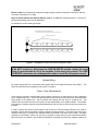
SCHOTT Solar, Inc. ASE-300-DGF/50 ASE 330,270,250 In this manual all references to ASE-300-DGF/50 refers to all the models listed above. Installation, Operation, and Maintenance Manual CONTENTS Read This First.............................................................................................................................. 1 Safety Instructions ........................................................................................................................ 2 Codes .............................................................................................................................................. 3 Applications - How Do I Position and Construct My PV System? .......................................... 4 Applications - How Do I Connect and Wire Up My PV System? ............................................ 7 Maintenance, Trouble-Shooting, & Repair .............................................................................. 11 Field Installation of Mounting Pins........................................................................................... 14 Product Specifications and IV Curve........................................................................................ 19 PM-00-003 Rev G ASE-300 Manual Read This First Thank you for buying a SCHOTT Solar Photovoltaic (PV) module. SCHOTT Solar combines decades of experience in photovoltaics with a commitment to bringing the benefits of solar electricity to people around the world. The module you have chosen is highly efficient, uses unique proprietary technology, is extremely rugged, and is designed to provide the longest life span of any photovoltaic (PV) module in the industry. Before wiring, installing or using a module, it is important to read this manual and understand the instructions. Installers should understand the basic principles of electricity and electrical appliances and article 690 of the National Electric Code. Special attention should be given to the safety instructions. Disclaimer of Liability Since the use of this manual and the conditions or methods of installation, operation, use, and maintenance of the module are beyond the control of SCHOTT Solar, SCHOTT Solar does not assume responsibility and expressly disclaims liability for loss, damage, or expense arising out of or in any way connected with such installation, operation, use, or maintenance. No responsibility is assumed by SCHOTT Solar for any infringement of patents or other rights of third parties which may result from use of the modules. No license is granted by implication or otherwise under any patent or patent rights. Important Safeguards Read this section carefully before installing, using, repairing, or performing maintenance on your PV modules or PV power system. • WARNING Lethal voltages and/or shock hazard may be present in modules and arrays during sunlight hours, even at low light levels. This hazard increases when multiple modules are connected together to provide higher system voltage or current levels. Dangerous voltages may also be present at night from connections to batteries and feedback from inverters or other parts of the system. PM-00-003 F 1 ASE-300 Manual Safety Instructions • Do NOT attempt to service any portion of the PV system unless you understand the electrical operation and are fully qualified to do so. • Use modules for their intended use only. Follow all module manufacturers’ instructions. Do NOT disassemble the module, or remove any part installed by SCHOTT Solar. • Do NOT attempt to open the diode housing or junction box located on the back side of any factory wired ASE-300DG modules. There are no user serviceable parts inside. • Do NOT use modules in systems that can exceed 600 volts (1000 – Euro version) open circuit under any combination of solar irradiation and ambient temperature. • Do NOT connect or disconnect a module unless the array string is open circuited or all of the modules in the string are covered. • Do NOT install during high winds. • Do NOT drop, allow objects to fall on, or stand or step on modules. • Do NOT work on modules when modules are wet. If a wet module is cracked or broken the full system voltage may be present in the water. • Do NOT attempt to remove snow or ice from the module. • Do NOT direct artificially concentrated sunlight on the module. • Do NOT wear jewelry when working on the modules. • A two-person (“buddy” system) is recommended while performing field work on all energized equipment where the system open circuit voltage is 30 volts or greater. • Wear electrical insulating gloves rated at 1000 volts and suitable eye protection when working on systems where the system open circuit voltage is 30 volts or greater. • Do NOT touch terminals while the module is exposed to light without wearing electrical insulating gloves. • Have a fire extinguisher, first aid kit, and electrical hook or cane available when performing field work on all energized equipment where the system open circuit voltage is 30 volts or greater. • Since sparks may be produced, do not install module where flammable gasses or vapors are present. PM-00-003 F 2 ASE-300 Manual Codes Underwriters Laboratories (UL) ASE-300-DG module is UL listed (qualified to UL 1703, Flat-Plate Photovoltaic Modules and Panels). This UL Standard “covers flat-plate photovoltaic modules and panels intended for installation on or integral with buildings, or to be freestanding (that is, not attached to buildings), in accordance with the National Electrical Code, NFPA 70, and Model Building Codes.” ASE-300-DG modules have a Class “A” fire rating (qualified to UL 94A.1). National Electrical Code (NEC) The National Electrical Code (NEC) covers the installation of photovoltaic systems and should be adhered to when systems are designed and installed. Article 690, Solar Photovoltaic Systems, of the NEC applies “to solar photovoltaic electrical energy systems including the array circuit(s), power conditioning units(s), and controller(s) for such systems.” IEC Listing ASE-300-DG modules meet the IEC 61215. Local Codes and Permits Before installation of modules and/or PV systems, contact appropriate authorities to determine local codes, permit, installation, and inspection requirements which apply. PM-00-003 F 3 ASE-300 Manual Applications - How Do I Position and Construct My PV System? Mounting Dimensions & Hardware The ASE-300-DG/50 module has 8 mounting holes. Four (4) holes are provided on the two long back flanges and four (4) additional holes are provided on the two short back flanges (See Figure 1). Attachment of the module to the support structure should be made at four (4) of these holes, either at the pairs of holes opposite each other on the long flanges, 914.4 mm (36.0”) apart, or at the pairs of holes opposite each other on the short flanges, 641.1 mm (25.24”) apart, using M10 or 3/8” bolts, nuts, and lock washers. Attachment must be made at no more than four (4) holes and must be made exclusively in the holes in the side (long) flanges or the holes in the end (short) flanges. Mounting the modules using both side flanges and end flanges could impose significant stress on the module and possibly damage it. It is recommended that external tooth “star” type lock washers be used to enhance the system ground path rather than the split ring type. It is highly recommended that either galvanized or stainless steel bolts, nuts, and washers be used to mitigate corrosion. Holes are also provided, through the web of the module frame members, at the same locations as the holes through the back flanges, and there are additional holes (total of 4), 2” in from each corner through the web of the frame end caps (short sides). These holes are sized to accommodate mounting pin assemblies, making it possible to mount the module using various bracket assemblies such as SCHOTT SunRoof™ FS System. PM-00-003 F 4 ASE-300 Manual "B" 25.3 (642.6mm) "A" "A" "B" 19.25 (488.95mm) "A" "A" DIODE HOUSING 74.5 (1892.3mm) 36.00 (914.40mm) Ø.410 (Ø10.414mm) MOUNTING HOLES (8X) MARKED "A" 72.9 (1852.7mm) "A" "A" GROUND POINT 10-32 THD INSERT & LABEL (4X) MARKED "B" .78 TYP (19.81mm) "B" "A" 12.63 (320.80mm) "A" "B" 25.24 (641.10mm) 48.9 (1243.1mm) 3.50 TYP (88.90mm) .78 (19.81mm) 50.5 (1282.7mm) ASE-300 MECHANICAL LAYOUT tolerance of +/- 1/8” to overall module dimensions (74.5 and 50.5) Figure 1 - ASE-300-DGF/50 Mechanical Layout PM-00-003 F 5 ASE-300 Manual • CAUTION Never leave a module unsupported or unsecured. If a module should fall, the glass could break. A module with broken glass cannot be repaired and must not be used. Clearance between Modules A clearance of 6 mm (1/4”) between modules is sufficient in most installations to accommodate thermal expansion. However, the appropriate clearance is dependent upon many installation specific factors including the support structure, temperature at the site, and the maximum operating temperature of the module. Orientation, Tilt Angle, and Shading Photovoltaic modules generate maximum power when facing directly towards the sun. Since applications and needs are different it is recommended that you consult a PV system integrator or use a commercially available software program to determine the expected energy output. The following paragraphs list some general rules of thumb. To maximize annual energy output, point the array south in the northern hemisphere and north in the southern hemisphere. Tilt the array from horizontal equal to site latitude. Your direction and tilt can vary depending on when you wish to maximize power output. Note that these orientations are true, not magnetic North and South. Dirt tends to accumulate on modules installed at flatter angles and does not wash off as readily during rainfall. Dirt accumulation on the module will reduce its energy output. Modules should be located in an unshadowed location where they will receive maximum exposure to the sunlight for the longest possible time during the day. Shadowing caused by buildings, trees, utility poles, and other obstructions, may significantly reduce the module energy output. If it is not possible to place the array in a shadow-free location, a location should be selected where there is no shading between the hours of 9 AM and 3 PM. This is the most energy-productive part of the day. Keep in mind that the worst case shading will occur on December 21 in the northern hemisphere and June 21 in the southern hemisphere. In systems that are configured with multiple rows of modules, the rows should be spaced far enough apart to minimize the impact of rows shading other rows. This distance is very dependent on the latitude at which the system is installed. The closer to the equator, the smaller this distance. The further from the equator, the greater is this distance. If there are questions regarding the optimum configuration in which to arrange and wire the modules, it is recommended that you obtain assistance from your SCHOTT Solar dealer or distributor or retain an engineer familiar with the design of PV systems. PM-00-003 F 6 ASE-300 Manual Applications - How Do I Connect and Wire Up My PV System? National Electrical Code Your PV system should be installed in accordance with the most recent version of the National Electric Code (NEC) Article 690, “Solar Photovoltaic Systems.” A copy of the NEC should be available at your local library. Module to Module Series Interconnection ASE-300-DG modules have been designed to be easily interconnected in series. Each ASE-300-DGF/50 module has two output wires, one positive (+) and the other negative (-), that are connected to the module inside of the diode housing. All ASE-300-DG modules come with connectors attached to the output wires. One output wire is fitted with a plug and the other is fitted with a receptacle. Modules are interconnected by inserting the plug from one module into the receptacle of the next module in the array string. The mated connector pair is then securely attached to the inside flange of the module frame to protect it from damage. Single Pole System The wires that exit the diode housing are single conductor wires. Each conductor is attached to either the positive or negative terminal inside the diode housing. To series connect modules, the plug connector of one module is inserted into the receptacle connector of the adjacent module. A return wire is needed to run from one end of the string to the other. Figure 3 - Single Pin Connectors Wiring Configuration The ASE-300-DG modules are designed for rapid installation. The wires have been installed and clipped to the frame in the factory. This eliminates the time consuming task of running wires in the field. The standard wiring configuration is landscape orientation (end mount). The module output cables can be unclipped to allow the module to be deployed in a portrait (side-mount) orientation. PM-00-003 F 7 ASE-300 Manual Landscape (End Mount) Portrait (Side Mount) Mounting Pins (Optional) Figure 4 - Module Orientations Building Source Circuits and Configuring Modules PV arrays are comprised of source circuits (from one to dozens or hundreds, depending upon the desired power). Source circuits are comprised of PV modules connected in series. The number of modules in a source circuit can vary depending on the module voltage, ambient temperature range, and desired system voltage, provided the max system voltage does not exceed that allowed by NEC Section 690-7 (600 volts). When calculating the system operation voltage use the module Vp. However, when calculation the max system voltage for the NEC compliance, use Voc. When determining component voltage ratings, conductor ampacities, fuse sizes, and size of controls connected to PV output, use the values of Isc and Voc marked on the module or found in the module Spec Sheet. NOTE Under certain normal conditions, a photovoltaic module is likely to experience conditions that produce more current and/or voltage than reported at standard test conditions. Accordingly, the values of Isc and Voc marked on this module should be multiplied by a factor of 1.25 (see Section 690-8 of the National PM-00-003 F 8 ASE-300 Manual Electric code) when determining component voltage ratings, conductor ampacities, fuse sizes, and size of controls connected to PV output. Refer to Section 690-8 of the National Electric code for an additional multiplying factor of 1.25 percent (80 percent derating) which may be applicable. An example for each module type follows: 400 Volt Array for 350 Volt Inverter 8 Module Source Circuit Combiner Box Figure 5 - Example of ASE-300-DG/50 Source Circuit • Do NOT connect or disconnect an ASE-300-DGF/50 module unless the array string is open-circuited or all of the modules in the string are covered. The ASE300-DGF/50 connectors are not designed to make or break the full system current. System Wiring All system wiring shall be in accordance with Section 690 of the National Electrical Code (NEC). The wires used should have a temperature rating of 90oC or higher. Fuses - Array Requirements Fuses may be required in a photovoltaic power system, both on the ac side and the dc side, depending on its complexity and size. This section will deal with the need for overcurrent devices in the photovoltaic array portion of the system only - that is between the modules and the array dc combiner box. The values of all overcurrent devices in the system are the responsibility of the system installer. The installer must install the module protective fuses described below and any other overcurrent devices required by the NEC. In order to protect the internal current paths of the module, an external module protective fuse must be installed in series with each module or string of series connected modules. The series fuse may have a maximum value up to 12 amps for the ASE-300-DG/50, as marked on the back of the module. If multiple modules are connected in series only one fuse is required for each string of series connected modules. When the fuses are located in the multiple string/module combining box where the separate modules or PM-00-003 F 9 ASE-300 Manual strings of modules are connected in parallel, then these fuses may also be used to provide the overcurrent protection for the module interconnections cables required by the NEC. The NEC requires that every ungrounded conductor be protected by an overcurrent device (fuse or circuit breaker). In a photovoltaic system with multiple sources of power (modules, batteries, battery chargers, generators, power conditioning systems, inverters, etc.) the overcurrent devices must protect the conductor from overcurrent from any source connected to that conductor. Blocking diodes, charge controllers, and inverters are NOT considered overcurrent devices and must be considered as zeroresistance wires. The main purpose for using over-current devices in an array field is to protect the wires interconnecting the modules, and the dc bus wires connecting groups of modules or sub-arrays, from seeing currents that exceed their ratings and pose a fire hazard. As the conductor size, used in the array wiring, increases to accommodate higher short-circuit currents of paralleled modules or groups of source circuits, each new conductor size must be protected by an appropriately sized overcurrent device. Bypass Diodes Each ASE-300-DGF/50 module comes with bypass diodes factory installed. These diodes protect the module against “hot-spot” heating. Hot spot heating occurs when a portion of a solar cell or cells are shaded or somehow isolated from the rest of the active cell or cells. A parked car or a person standing in front of the modules can cause a short term shading situation. Leaves or bird droppings can cause a long term shading situation. Independent tests show that a 25% shading of a solar cell can create the highest “hot spot” temperature. This means that 25% of the solar cell is inactive. The remaining 75% of the cell is active, but must run at an amperage (current) of a 100% active solar cell. The result is that that active part of the solar cell will dissipate heat. In the event of such a shading condition, the bypass diodes turn on and redirect the current around the string of cells that have the shaded condition. In effect, the bypass diode disconnects the string of cells from the rest of the circuit. It reduces the power output of the module but it also avoids the serious damage that can be caused by “hot-spot” heating. The bypass diodes are contained in the diode housing located on the back of the module. Regardless of the module type, SCHOTT Solar puts a bypass diode around every 18 connected series cell group. The number of parallel strings within a group differs between the module types. The chart below describes the differences: Module Type ASE-300-DG/50 No. of Diodes in Module No. of Parallel 18 Cell Strings per Diode 6 Amount of Power Reduction When One Diode Turns On 2 18.7% Blocking Diodes Blocking Diodes (also known as series or isolation diodes) are placed in series with a module or string of series-wired modules, to prevent current from flowing backwards through the modules. This is particularly important in systems with battery storage. At night or during inclement weather, the batteries may be drained by current flowing into the modules and dissipating as heat. A blocking diode will stop this. The number, capacity, and installation of the blocking diodes are the responsibility of the system designer, integrator, or installer. ASE-300-DGF/50 modules do not come with blocking diodes. Module Grounding Ground points are provided in the form of 10-32 threaded inserts, located on the bottom flanges of the module frame members, near the four corners, and are labeled with a “GR” symbol (see figure 1). PM-00-003 F 10 ASE-300 Manual A ground clamp, 10-32 hex bolt, and lock washer are provided with each module for use with one of the module ground points. The ground clamp should be installed from the bottom side of the frame using the lock washer and bolt. The hex bolt should be torqued to 50-70 in-lbs. This ground hardware can accommodate a #6 AWG through #12 AWG bare (stranded or solid) wire. See NEC Section 690-E for module grounding requirements. Maintenance, Trouble-Shooting, & Repair Maintenance The maintenance requirements for the modules are minimal. If the modules become dirty they may be washed off as the dirt reduces the power produced. The suggested method is to use the force of the water from a hose to remove the dirt. A mild non-abrasive detergent is optional. Cleaning modules is best done in the early morning or late afternoon when the modules are relatively cool. Spraying cold water on extremely hot modules could result in breakage due to thermal shock. If the water that is being used to clean the modules has a high mineral content, you may want to use a squeegee to clear excess water off the module in order to avoid the build up of mineral deposits. It is helpful to record the system performance before and after the cleaning in order to gauge the impact of the cleaning procedure. Keep in mind that the water will have a cooling affect on the modules, which will have a tendency to temporarily enhance performance figures until the module returns to normal operating temperature. Periodic visual inspection of the PV modules and their interconnections is recommended. Modules should be inspected for any damage including broken glass, or connector and wire damage. Damaged components should be repaired and broken modules replaced. A voltmeter is highly recommended for verifying that the system is operating properly and for checking system components. Troubleshooting A photovoltaic module will produce electricity when illuminated. Treat solar modules in the same way you would treat any electrical device. Only personnel trained in the use and handling of PV modules should attempt any diagnostic work. • WARNING Consult all Safety Instructions (see Important Safeguards section) and WARNINGS in this document before doing any work with the photovoltaic modules. Photovoltaic system malfunctions can, in rare cases, be caused by module failures. Therefore, it may become necessary to field check modules for proper operation. Field conditions vary widely. Since the module output is a function of sunlight and temperature, it can be difficult to determine what an appropriate field electrical reading should be. Subtle problems will not likely be determined in the field; however gross ones should be detectable. One of the best ways to determine if a module is malfunctioning is to compare readings between modules. Similar readings would indicate that the module in question is within specifications. Wide differences, >20%, would most likely indicate a module problem. PM-00-003 F 11 ASE-300 Manual There are two module electrical parameters that can be readily measured in the field that will give an indication if the module is functioning properly. These two parameters are the short circuit current (Isc) and the open circuit voltage (Voc). They are typically measured with a multimeter (an instrument that measures current, voltage, and resistance in circuits). Reading the voltage across the positive (+) and the negative (-) terminal/leads of the disconnected module will give the Voc. Shorting the leads together and placing an ammeter in the circuit will give you the Isc. Comparing these readings between several modules will identify any under or non performing module(s) CAUTION: Short-circuiting the output of a solar module, or group of modules, is a potentially hazardous operation. Observe proper safety procedures when working with high voltage direct current (wear high voltage gloves and eye protection, and work with a partner). Confirm that the multimeter is able to withstand the anticipated short-circuit current. It is also possible to compare these readings to the module specifications. However, the specifications are determined at a designated solar irradiance and a designated ambient temperature, e.g., “STC” (see prior section Specifications - Electrical Characteristics above). If the field measurements are not made under conditions which match STC, the Isc and Voc values will be different. For larger systems another useful test can be made using a current probe attachment for the multimeter. A current probe is a device that has jaws that open to allow it to be placed around the wire instead of inline with the wire. This device can measure current without breaking the circuit. The use of an inductive type current probe is preferred, and much safer than passing current directly through the multimeter. Using the current probe, currents can be easily measured in each source circuit in the array and compared one to one another. If they are the same it is likely the module(s) in question is functioning properly and if different, it is likely that the module(s) in question is not functioning properly. When evaluating the readings one should keep in mind that module current is directly proportional to the amount of solar irradiation and module voltage is dependent on the module temperature. The published specifications are referenced to STC conditions, 1000 W/m2, AM=1.5 spectrum, and a cell temperature of 25 oC. A decrease in light intensity of 50% will reduce the current by 50% with the voltage remaining essentially unchanged. An increase in the cell temperature by 10oC, caused by the sun striking the module or by the ambient air temperature rising, will reduce the voltage by 3.8% with the current remaining essentially unchanged. Abnormal readings should alert the user to possible module problems. Replacing suspicious modules with known good ones will help confirm the diagnosis. Any module problems should be brought to the attention of your installer, distributor, or SCHOTT Solar. PM-00-003 F 12 ASE-300 Manual Repair All module repairs must take place at the factory, or under the supervision of factory trained personnel. Before sending a module back, contact the module seller for authorization and return. Make sure you have the module serial number available (on the module label). • WARNING Consult all Safety Instructions (see Important Safeguard section) and WARNINGS in this document before doing any work with the photovoltaic modules. Do NOT connect or disconnect an ASE-300-DGF/50 module unless the array string is open circuited or all of the modules in the string are covered. The connectors on these modules are not designed to make or break the full system current. It should be noted that most problems that occur in a photovoltaic power system are not caused by the photovoltaic modules. The most common problem is a bad or improper connection. Before considering returning a suspect module to the factory, check the tightness of the connection to adjacent modules. Look for signs of arcing. If the connector or wiring appears to be damaged, a trained technician should be able to repair the module at the site. If connections and wiring look good but the module does not seem to be working properly, return the module to the seller. PM-00-003 F 13 ASE-300 Manual Field Installation of Mounting Pins The following instructions are provided to assist in the field installation of mounting pins on the ASE 300 module. These instructions show the proper installation as well as highlight possible safety hazards with incorrect mounting of pins. MATERIALS Each pin assembly consists of the following materials – Qty (1) Hex head bolt, 1/4-20 x 1-1/2” Qty (3) Washers, 1/4” Qty (1) Ferrule (sleeve) Qty (1) Hex nuts, Nylock, 1/4” EQUIPMENT / TOOLS The following tools are required – Box end wrench 7/16” Ratchet socket wrench with 7/16” INSTALLATION STEPS IMPORTANT! Read the instructions completely before installing the pins. Take care not to damage the module output cables between the washer and the inside module frame. Damaged electrical cables could create electrical shock hazards. Do not use a module with damaged output cables. The following steps illustrate how to install the mounting pins – The installation of the pin assemblies is easier if the module can be laid face-down on a non-scratch surface (such as clean cardboard without staples). However, the pin assemblies can be installed with the modules either face up or face down. For the FS mounting system, the pin assemblies go into the four holes on the short frames on the module. Assemble the mounting pin components and orient as shown in Figure 1. Note that from the outside of the module, the correct order is bolt head, washer, ferrule, washer, the module frame, washer and the nylock nut. Figure 1 – Mounting Pin Assembly PM-00-003 F 14 ASE-300 Manual When inserting and tightening the mounting pin parts, check to ensure that the washer and hex nut inside the module frame do not pinch or compress the cables. Pinching or compressing the cables can damage the wiring insulation and create electrical hazards. See Figures 4, 5 and 6 below. Tighten the bolt and nut until snug, but do not over-tighten. Over-tightening can crush the pin components or module frame. The mounting pin should look like Figure 2 when viewed from outside the frame. Figure 2 – Head of Mounting Pin Outside of Frame PM-00-003 F 15 ASE-300 Manual EXAMPLES OF CORRECT AND INCORRECT CABLE ROUTING Figure 3 –Washer and Nut Placement Inside Module Frame Figure 4 – Correct Routing of Cable over Washer Figure 5 – Correct Routing of Multiple Cables Figure 6 – Incorrect Routing (Cables pass over washer) (Cables are under washer) PM-00-003 F (Cable passes over washer) 16 ASE-300 Manual Double Glass Module Warranty Rev Date: April 4, 2006 [WA-MK-001 Rev. D] SCHOTT Solar, Inc. LIMITED WARRANTIES for Double Glass Modules (1) The limited warranties specified in paragraphs (2) and (3) below extend only to the first retail purchaser of the product(s), and subsequent owners of building(s) on which the product(s) is first installed (the "Buyer"). (2) SCHOTT Solar Inc. (“SCHOTT Solar”) warrants to Buyer that its standard solar cell modules (including diodes, wiring and accessories if supplied by SCHOTT Solar) furnished hereunder will, a) at the time of original shipment by SCHOTT Solar, be free and clear of all liens and encumbrances and, b) for a period of one (1) year from the date of purchase by Buyer, will be free from defects in material and workmanship and will conform to SCHOTT Solar’s applicable specifications. SCHOTT Solar’s obligations under this paragraph shall be limited, at its option, to repair, replacement or refund to Buyer of the purchase price of any defective or nonconforming product(s). (3) SCHOTT Solar further warrants to Buyer the specified power output of its standard solar cell modules for a period of twenty (20) years from the date of purchase by Buyer. During such time, SCHOTT Solar will at its option, subject to paragraph (4) below, repair, replace or add additional modules in order to make up for any power loss of greater than (i) Ten Percent (10%) during the first ten (10) years and (ii) twenty percent (20%) during the first twenty (20) years, (as determined by testing procedures approved by SCHOTT Solar and, at SCHOTT Solar’s option, tests conducted under the supervision of authorized SCHOTT Solar personnel) of the original SCHOTT Solar specified power output at time of shipment provided such power loss is determined by SCHOTT Solar to be due to defective materials or workmanship of the products supplied by SCHOTT Solar. (4) All claims under the warranties specified in paragraphs (2) and (3) above must be made in writing addressed to SCHOTT Solar Customer Service, 2260 Lava Ridge Court, Suite 102, Roseville, CA 95661, within ten (10) days after discovery of the basis for the claim and must set forth the complete details of such claim. Every claim under the limited warranties specified in paragraph (2) above shall be deemed waived by Buyer unless made in writing to SCHOTT Solar within one (1) year from the date of Buyer’s purchase of the product(s) to which such claim relates. Every claim under the limited warranties specified in paragraph (3) shall be deemed waived by Buyer unless made in writing to SCHOTT Solar within (i) ten (10) years for claims under paragraph (3)(i) above, and (ii) twenty (20) years for claims under paragraph (3)(ii) above, from the date of Buyer’s purchase of the product(s) to which such claim relates. No product(s) may be returned to SCHOTT Solar without written authorization from SCHOTT Solar. Authorized returns must be made to SCHOTT Solar at the following address: SCHOTT Solar, 4 Suburban Park Drive, Billerica, MA 01821. All shipping costs for returns must be prepaid by Buyer, within thirty (30) days of a written return authorization. SCHOTT Solar will pay shipping costs for return to Buyer of any product(s), which is (are) repaired or replaced under the terms of this limited warranty. However, if product(s) returned to SCHOTT Solar is (are) found not to be defective or the warranties have expired, Buyer is responsible to pay for return shipping costs. Unless made in conformance with this paragraph, any claims hereunder shall be deemed waived by Buyer and void. (5) The warranties of paragraphs (2) and (3) shall not apply to any products which SCHOTT Solar determines have been subjected to: any assembly or processing that alters physical or electrical properties; improper installation, maintenance or use; mishandling; abuse; neglect; vandalism; improper testing; repair; alteration; damage; fire; flood; civil disturbances; war; or other acts or omissions which alter physical or electrical properties. The warranties also shall not apply to any use of the products in automotive or recreational vehicle applications. The warranties shall not apply to product(s) installed at any location other than North America and South America, unless expressly granted in writing by SCHOTT Solar. (6) The warranties of paragraphs (2) and (3) are in lieu of all other warranties. WARRANTIES IMPLIED BY LAW, IF ANY, INCLUDING BUT NOT LIMITED TO ANY IMPLIED WARRANTIES OF MERCHANTABILITY AND FITNESS FOR A PARTICULAR PURPOSE, ARE HEREBY LIMITED IN DURATION TO ONE (1) YEAR FROM THE DATE OF PURCHASE BY BUYER. SOME STATES DO NOT ALLOW LIMITATIONS ON HOW LONG AN IMPLIED WARRANTY LASTS, SO THE ABOVE LIMITATION MAY NOT APPLY TO YOU. (7) SCHOTT Solar’s entire liability to Buyer under these warranties is expressly limited to performance of the remedies specified herein and shall not exceed Buyer’s purchase price for the product(s). IN NO EVENT SHALL SCHOTT SOLAR BE LIABLE UNDER THIS WARRANTY FOR PERSONAL INJURY OR PROPERTY DAMAGE OR FOR INCIDENTAL OR CONSEQUENTIAL DAMAGES OR LOST PROFITS, WHETHER SUCH DAMAGES ARE BASED ON NEGLIGENCE, CONTRACT, TORT, STRICT LIABILITY OR OTHERWISE. SOME STATES DO NOT ALLOW THE EXCLUSION OR LIMITATION OF PERSONAL INJURY OR PROPERTY DAMAGES OR OF INCIDENTAL OR CONSEQUENTIAL DAMAGES, SO THE ABOVE LIMITATIONS OR EXCLUSIONS MAY NOT APPLY TO YOU. (8) NO OTHER WARRANTIES. SCHOTT Solar does not warrant or guarantee any products, services, materials, goods or accessories except as specifically set forth in this warranty statement, including but not limited to any products covered by this quotation that are not manufactured by SCHOTT Solar. IN ANY EVENT, SCHOTT SOLAR SHALL NOT BE LIABLE FOR ANY CLAIMS OR DAMAGES, WHETHER BASED UPON BREACH OF EXPRESS OR IMPLIED WARRANTIES, NEGLIGENCE OR OTHERWISEINCLUDING ANY LIABILITY FOR CONSEQUENTIAL, INDIRECT OR SPECIAL DAMAGES OR FOR ANY EXPENSE INCURRED BY REASON OF THE USE, SALE, SERVICING OR FABRICATION OF SUCH PRODUCTS. PM-00-003 F 17 ASE-300 Manual (9) THIS WARRANTY GIVES YOU SPECIFIC LEGAL RIGHTS, AND YOU MAY ALSO HAVE OTHER RIGHTS WHICH VARY FROM STATE TO STATE. For additional information: For a list of local dealers and distributors Visit our website at www.us.schott.com/solar or contact our sales office at: SCHOTT Solar, Inc. Mail: 2260 Lava Ridge Court, Suite #102, Roseville, CA 95661 Email: [email protected] Phone: (888) 45-SOLAR or (916) 774-3000 Copyright 2006 SCHOTT Solar, Inc. All rights reserved. Printed in U.S.A. 8/15/06 PM-00-003 F 18 ASE-300 Manual Product Specifications and IV Curve ASE-300-DGF/50 Product Specification Sheet Construction Solar Cells 100 mm sq Crystalline Number of Cells 216 Encapsulant Advanced Front Cover 3 mm(1/8”) tempered low iron glass Back Cover 3 mm(1/8”) tempered glass Frame Mill finish Aluminum By-pass diodes 6 Termination 10AWG w/Single Pole Quick Connects Physical Length mm (in) Width mm (in) Weight kg (lbs) Wire Length 1892.3 (74.5”) 1282.7 (50.5”) 46.2 +/- 2 kg (107 +/- 5 lbs) (+) 2845(112”) (-) 1448 (57”) Dimensional tolerances are +/- 3.0 mm (1/8”) Warranty and Certifications UL 1703 Yes Fire Rating Class A IEC 61215 Yes IEEE 1262 Yes Schutzkasse II Yes Warranty 10 yr/10% & 20 yr/20% Electrical Conditions HiPot Voltage Max System Voltage 2200 Volts 600 Volts Environmental Conditions Max Cell temp** Min Cell Temp Relative Humidity Tested Wind Conditions 90 C -40C 0-100% 192kn/hr (120mph) equivalent ** Under full sunlight, cell temperature is typically 25-30C above ambient PM-00-003 F 19 ASE-300 Manual Product Specifications and IV Curve ASE-300-DGF/50 Product Specification Sheet (continued) Cell temperature coefficients Power Pp -.047%/°C Open-circuit Voltage Voc -.038%/°C Short-circuit Current Isc +.10%/°C Electrical Conditions Model No. ASE-250DGF/50 CEC Model No. ASE-250DGF/50-230 Pp Range Voc Isc Vp Ip Label Watts DC 225 Volts DC Amps DC Volts DC Amps DC 59.3 5.5 47.5 4.8 59.8 5.6 47.9 5.0 60.3 5.8 48.3 5.2 60.8 5.9 48.7 5.3 61.3 6.1 49.1 5.5 61.9 6.2 49.6 5.7 62.5 6.4 50.1 5.8 63.2 6.5 50.6 5.9 63.8 6.7 51.1 6.1 64.4 6.8 51.6 6.2 65.0 7.0 52.1 6.3 65.7 7.1 52.6 6.5 66.3 7.3 53.1 6.6 230 235 ASE-250DGF/50 ASE-250DGF/50-240 240 245 ASE-250DGF/50 ASE-250DGF/50-250 250 255 ASE-270DGF/50 ASE-270DGF/50-260 260 265 ASE-270DGF/50 ASE-270DGF/50-270 270 275 ASE-300DGF/50 ASE-300DGF/50-280 280 285 ASE-300DGF/50 ASE-300DGF/50-290 290 295 ASE-300DGF/50 ASE-300DGF/50-300 300 305 ASE-300DGF/50 ASE-300DGF/50-310 310 315 ASE-300DGF/50 ASE-300DGF/50-320 320 325 ASE-330DGF/50 ASE-330DGF/50-330 330 335 ASE-330DGF/50 ASE-330DGF/50-340 340 345 ASE-330DGF/50 ASE-330DGF/50-350 Standard Packaging Qty Crate weight – kg (lbs) Crate height – m (in) Crate width – m (in) Crate length – m (in) PM-00-003 F 350 20 1088 KG (2400 lbs) 2.08m (83”) 1.13m (44.5”) 1.38 m(54.5”) 20 ASE-300 Manual Product Specifications and IV Curve ASE-300-DGF/50 Product Specification Sheet (continued) Typical I-V Curve ASE 300-DGF/50-300 watt PM-00-003 F 21 ASE-300 Manual