1
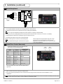
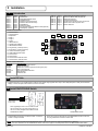
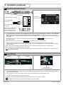
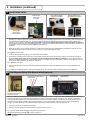
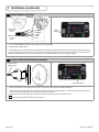
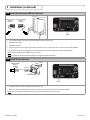
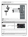
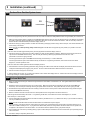
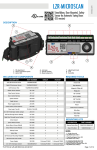
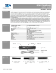
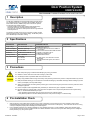
Door Position System USER’S GUIDE PROGRAMMABLE LOCKOUT MODULE WITH DOOR POSITION 1 Description The DP-Hub (10DPHUB) is a programmable lockout module used for any automatic swing door in conjunction with the EDPS, Enhanced Door Position Sensor, (10EDPS) to provide accurate door position. The accurate door position provides: - Automatic inhibiting of the safety side Door Mounted Sensor(s) without the need for an external mechanical limit switch. - A manual push of the door or stack pressure will no longer effect the overhead presence. The hub also provides sensor plug-in connectors, and easy 2-button digital programming with a user-friendly display. The DP-Hub product line is identified by a solid black housing. 2 Specifications DESCRIPTION SPECIFICATION COMPONENT INPUTS COMPONENT OUTPUTS Supply voltage 12 to 24 VAC/VDC: +/- 10% (2) Door Control Power consumption 80mA max. (hub only) Temperature range -20°F to +150°F Dimensions 4.5” W x 2.5” D x 1.25” H Housing material ABS – Solid Black (2) Eagle Motion Sensors (1) BodyGuard Sensor */** (2) Pair of Door Mounted Sensors w/ EDPS & Home switch (2) Manual Door Mounted Stall Inhibit Terminals (1) Auxiliary: Push Plates, RF, etc. (1) SBK 30 Photo Beam pair (1) ON/OFF/HOLD Switch Relay Specifications 2A, 30 VDC .3A, 110 VDC .5A, 125 VAC * For dual egress, use Y-harness for second BodyGuard. ** For independent dual egress, two hubs are required. 3 Precautions Shut off all power going to header before attempting any wiring procedures. Maintain a clean & safe environment when working in public areas. Constantly be aware of pedestrian traffic around the door area. Always stop pedestrian traffic through the doorway when performing tests that may result in unexpected reactions by the door. ESD (electrostatic discharge): Circuit boards are vulnerable to damage by electrostatic discharge. Before handling any board ensure you dissipate your body’s ESD charge. Always check placement of all wiring before powering up to ensure that moving door parts will not catch any wires and cause damage to equipment. Ensure compliance with all applicable safety standards (i.e. ANSI A156.10) upon completion of installation. DO NOT attempt any internal repair of the components. All repairs and/or component replacements must be performed by BEA, Inc. Unauthorized disassembly or repair: 1. May jeopardize personal safety and may expose one to the risk of electrical shock. 2. May adversely affect the safe and reliable performance of the product resulting in a voided warranty. 4 Pre-Installation Check 1. When preparing to wire multiple devices together for a ‘system’ configuration, it is best to ensure the correct operation of each device independently before starting thereby reducing troubleshooting time later in the event of a discrepancy. Thus make sure the door is running correctly and adjusted properly before installing Door Position System. 2. Prior to installing equipment on an existing installation or when installing equipment on a new installation, utilizing new electrical supply circuits, always ensure the correct line voltage exists and is stable. Remember to disconnect the power after checking the line voltage and before performing any wiring to the system. 75.5652.03 20130617 Page 1 of 16 5 Installation (continued) 4 Install BodyGuard RED BLACK WHITE GREEEN BodyGuard Cable Route to ‘BG’ BROWN BLUE 1 PWR 2 PWR 3 COM 4 NO 5 NC 6 IN 7 IN + 10 PIN BodyGuard 10 PIN 1. For complete installation instructions refer to BodyGuard User’s Guide (75.5134). NOTE: BEA recommends the use of the Bodymount during all Bodyguard installations. NOTE: On a single door installation the Bodyguard should be angled to 10 degrees (5 degrees default). 2. Plug ten pin connector into BodyGuard as shown above (hard wire as shown above only if ten pin connector is not available). 3. Route BodyGuard Cable Harness (20.5082) through door header to DP-Hub. 4. Plug BodyGuard Cable into DP-Hub at location labeled ‘BG’. NOTE: For dual egress use Y-harness for second BodyGuard. NOTE: For independent dual egrees, two DP-Hubs are required. 5 NOTE: BodyGuard Jumper (BodyGuard plug with orange jumper wire) can be used to setup the system when the BodyGuard is on the door header cover. It can also be used in low energy applications. Install Door Control Harness(s) The DP-Hub provides two door control outputs for door controls that cannot be paralleled together. WIRE OUTPUT Green Activation NO Yellow Activation NC ‘TYPICAL’ DOOR CONTROL White Activation COM COM Safety NO SAFETY Yellow/Black Safety NC White/Black Safety COM COM STALL Green/Red Stall NO Stall NC White/Red Stall COM Door Control 2 ACTIVATION Green/Black Yellow/Red Door Control 1 STALL COM For a list of specific door control connections please refer to Appendix B. 1. Make connections to the door control(s) as displayed above. 2. Route wiring harness(s) (20.5222) from door control to DP-Hub and plug into DP-Hub at location marked ‘CONTROL 1’ and/or ‘CONTROL 2’. NOTE: Typically on the door control, the common (COM) for the Stall input is isolated from the common for Activation and Safety. If the door control has one common input, tie all the common outputs from the DP-Hub together. 75.5652.03 20130617 Page 3 of 16 5 Installation 1 Introduction STEP 1 : STEP 2 : STEP 3 : STEP 4 : STEP 5 : STEP 6 : STEP 7 : STEP 8 : STEP 9 : STEP 10: Page 2: Page 2: Page 2: Page 3: Page 3: Page 4: Page 4: Page 5: Page 5: Page 6: Introduction Install DP-Hub Install ON/OFF/HOLD Switch Install BodyGuard Install Door Control Harness(s) Install Door Mounted Sensor(s) Install EDPS(s) Install Home Switch Door Mounted Safety Side Manual Inhibit (optional) Install Eagle(s) (optional) STEP 11: STEP 12: STEP 13: STEP 14: STEP 15: STEP 16: STEP 17: Page 6: Page 7: Page 7: Page 8: Page 8: Page 9: Page 9: Install Auxiliary/Push Plate(s) (optional) Install Photo Beams SBK-30 (optional) Install Power Harness Configure BodyGuard III Check Function Number of Doors on DP-Hub Perform Door Position System Learn Perform Walk Test CONNECTION DIAGRAM: 1 2 3 4 5 6 7 8 9 10 11 12 13 14 15 16 17 Door Mounted 1 Door Mounted 2 BodyGuard Eagle 1 Eagle 2 Power SBK-30 Beams Auxiliary/Push Plate(s) ON/OFF/HOLD Switch Programming - FUNC (Function) Programming - INCR (Increment) Learn/Home/Tracking LEDs Safety/Stall/Activation LEDs Door Control 2 Door Control 1 Door Mounted 2 Manual Inhibit Door Mounted 1 Manual Inhibit 16 17 15 14 13 12 1 2 11 3 4 10 5 6 7 8 9 INSTALLATION HARNESSES: BEA P/N: 20.5078.02 20.5082 20.5083 20.5222 20.5215.02 20.5096 20.5095 2 DESCRIPTION: ON/OFF/HOLD Switch Harness BodyGuard Harness BodyGuard Y Harness (optional for dual egress pair) Door Control Harness Door Mounted/EDPS Harness Eagle Harness Power Harness Install DP-Hub 1. Install the DP-Hub in an accessible location inside the door header using supplied velcro strips. Allow adequate space to easily see the DP-Hub display, to access the push buttons and to access all connectors. 3 Install ON/OFF/HOLD Switch Switch Cable Route to ‘SW’ WHITE BLACK RED When upgrading from an LO-Linx make sure that the wire colors are in the order shown above, as the LO-Linx was packaged with a different model ON/OFF/HOLD Switch. 1. Install ON/OFF/HOLD Switch in desired location. Ensure the location is easily accessible. ON/OFF/HOLD Switch 2. Route wiring harness (20.5078.02) from ON/OFF/HOLD Switch to DP-Hub and plug into DP-Hub at location marked ‘SW’. NOTE: When changing the state of the ON/OFF/HOLD switch, the door will not open or close if the Bodyguard is in detection. NOTE: If the door control also has an ON/OFF/HOLD switch, make sure to jump it to the ON position and use the BEA ON/OFF/HOLD Switch. Page 2 of 16 75.5652.03 20130617 5 Installation (continued) 6 Install Door Mounted Sensor(s) Door Mounted 1 Door Mounted 2 EMPTY 1 (SuperScan shown in example) INHIB GND 2 INHIB + 3 N.O. 4 Door Mounted 1 Cable Route to ‘DM 1’ Door Mounted 2 Cable Route to ‘DM2’ Make sure to set the SuperScan’s JP2 to the default (as shown) to make the SuperScan have a closed contact during detection. GREEN N.C. 5 WHITE COM 6 BLACK PWR 7 RED PWR 8 Led Pot JP2 1. For complete installation instructions refer to appropriate Door Mounted Sensor User’s Guide (SuperScan or QuadScan). For a new install, please make sure to use the DPS Door Mounted Sensor Extrusion Mounting Template, in order to get the extrusion(s) with end caps installed, approximately 1” apart. For a retro fit where the 1” apart cannot be obtained or for more precise Home Switch installation, please refer to Appendix C. 2. Wire Door Mounted Sensor (SuperScan displayed in this example) harness labeled Door Mounted Sensor. 3. Wire Door Mounted Sensor harness labeled to the approach/push side to the safety/swing side Door Mounted Sensor. 4. Route wiring harness (20.5215.02) from the Door Mounted Sensor to DP-Hub and plug into DP-Hub at location marked ‘DM1’. Also note that the extra ten pin connector on the harness should also be routed to the safety side of the door as it will be used for the EDPS installation in Step 7. For a two door system, repeat steps above with the second door, except route the second wiring harness from the Door Mounted Sensor to DP-Hub and plug into DP-Hub at location marked ‘DM2’. NOTE: If the door system has reflective guide rails (for example; stainless steel) set the hold time on the safety side door mounted sensor(s) to approximately one second. 7 Install EDPS(s) SuperScan EDPS SuperScan SuperScan (shown in example) 10 pin plug from Door Mounted Sensor Cable 1. Install the EDPS (Enhanced Door Position Sensor) into the safety side Door Mounted Sensor extrusion as close to the center as possible as shown above with SuperScans. 2. Plug the previously routed ten pin connector in Step 6 from wiring harness (20.5215.02) into EDPS as shown above. For a two door system, repeat steps above with the second door. NOTE: When the DP-Hub is powered the EDPS green LED will illuminate to let you know that it is powered. NOTE: The EDPS must be placed at the 0 degree angle (horizontal) in the clips as shipped. Page 4 of 16 75.5652.03 20130617 5 Installation (continued) 8 Install Home Switch Magnetic reed switch wired into EDPS Surface Mount Adapter exploded and Installed Magnet installed in end cap exploded and installed End cap with Home Switch Collar exploded 1. Snap the Home Switch Collar with the magnetic reed switch into the correct end cap and install the end cap on the Door Mounted Sensor extrusion. For a one door system, the correct end cap will be the cap on the leading edge of the door. For a two door system, the correct end cap will be the leading edge or either door. The default installation will have the magnetic reed switch flush with the collar, however some adjustment may be required. For a new install, please make sure to use the DPS Door Mounted Sensor Extrusion Mounting Template, in order to get the extrusion with end cap installed approximately 1” apart from the surface mount adapter. For a retro fit where the 1” apart can not be obtained or for more precise Home Switch installation, please refer to Appendix C. 2. Route the two wires from the magnetic reed switch to screw terminal on the previously installed EDPS ensuring that the wires are out of the Door Mounted Sensor’s pattern (orientation of the two wires to the screw terminal does not matter). For a typical one door system: 3. Press the supplied magnet into the top piece of the surface mount adapter. 4. Press the top and bottom pieces of the surface mount adapter together and install on the door jamb, using the two screws as shown above. For a new install, please make sure to use the DPS Door Mounted Sensor Extrusion Mounting Template, in order to get the extrusion with end cap installed approximately 1” apart from the surface mount adapter. For a retro fit where the 1” apart can not be obtained or for more precise Home Switch installation, please refer to Appendix C. For a typical two door system: 3. Snap the supplied magnet into the second Door Mounted Sensor extrusion end cap and install the end cap on the Door Mounted Sensor extrusion. If you cannot use the typical installation, there are several alternatives. For more Home Switch information please refer to Appendix C. 9 Door Mounted Safety Side Manual Inhibit (optional) Door Mounted Sensor Manual Inhibit Jumper Door Mounted 1 Manual Inhibit Door Mounted 2 Manual Inhibit Door Mounted Sensor needs inhibited automatically by DP-Hub or manually Manually inhibiting the Door Mounted Safety Side Sensor(s) is completely optional due to the fact the DP-Hub will automatically learn the location at which those sensor(s) go into detection during the learn cycle and then inhibit them during all consequent cycles. However if preferred to manually inhibit those sensors using a mechanical limit switch, there are two positions available on the DP-Hub. The switch(es) must open its contacts at the desired point of inhibiting. When these terminals are not used, they should be jumpered using the jumper included with the package. If manually inhibiting of a Door Mounted Safety Side Sensor(s) is desired at some point in the opening cycle: 1. Cut the grey jumper wire for ‘MANUAL Stall Inhibit 1’. 2. Wire the mechanical inhibit switch to the previously cut jumper wires and wire nut. For a two door system, repeat steps above using the orange jumper wire. NOTE: See Programming Parameter FM on page 10 section 6-1. 75.5652.03 20130617 Page 5 of 16 5 Installation (continued) 10 Install Eagle(s) (optional) Eagle 1 Cable Route to ‘EG 1’ RED BLACK WHITE GREEN Eagle 2 Cable Route to ‘EG 2’ 1 2 3 4 5 POWER POWER COM N.O. N.C. Eagle 1 Eagle 2 1. For complete installation instructions refer to Eagle User’s Guide (75.0058). 2. Wire Eagle as displayed above. 3. Mount Eagle Sensor to door header and route Eagle harness (20.5096) through door header and plug into DP-Hub at location marked ‘EG1’. For two way traffic, repeat the steps above on the opposite side of the door and plug into DP-Hub at location marked ‘EG2’ and make sure that the Eagle is installed beyond the swing of the door so that the normal operation of the door does not trigger the Eagle. 11 Install Auxiliary/Push Plate(s) (optional) Push Plate Wire Route to ‘AUX’ COM NO NC Auxiliary/Push Plate 1. Mount Push Plate(s) or other Knowing Act device(s) to wall, jamb or desired location accessible to traffic flow. 2. Route two wires from Push Plate to DP-Hub and fasten one leg of Push Plate at the first location of screw terminal marked ‘AUX’ on DP-Hub and the second leg of Push Plate to second location marked ‘AUX’ on DP-Hub. NOTE: Make sure the device is wired to the normally-opened (NO) and common (COM) contacts of the device. NOTE: See Programming Parameter FA on page 10 section 6-1. Page 6 of 16 75.5652.03 20130617 5 Installation (continued) 12 Install Photo Beams SBK-30 (Optional) Beams TX Cable Route to ‘BEAMS’ Beams RX Cable Route to ‘BEAMS’ Beams 1. For complete installation instructions refer to Beams SBK-30 Users Guide (75.5179). 2. Install Beam Transmitter. 3. Install Beam Receiver. 4. Route wiring harness (20.5099) from the Transmitter to DP-Hub and plug into DP-Hub at either one of the locations marked ‘BEAMS’. 5. Route wiring harness (20.5100) from the Receiver to DP-Hub and plug into DP-Hub at the other location marked ‘BEAMS’. NOTE: See Programming Parameter FB on page 10 section 6-1. NOTE: If using beams, the DP-Hub will automatically be set to Advanced BodyGuard Safety. 13 Install Power Harness POWER CABLE Route to POWER RED RED BLACK 115 VAC RED 24 VAC BLACK BLACK 24 V TRANSFORMER Power 1. Install transformer in an easily accessible location to the DP-Hub. 2. Route wiring harness (20.5095) from the Transformer to DP-Hub and plug into DP-Hub at location marked ‘POWER’. NOTE: Alwasy use the BEA supplied transformer and never power the DP-Hub from the door control. 75.5652.03 20130617 Page 7 of 16 5 Installation (continued) 14 Configure BodyGuard III BODYGUARD III 1. Unlock BodyGuard Sensor 2. Set Output Configuration to 3. Lock Sensor by pressing Lock 2 Normally Closed OUTPUT CONFIGURATION twice 1 2 - Normally OPEN Relay (default) 1 2 3 4 5 6 7 8 9 F1 0 F2 - Normally Closed Relay + ? CAUTION: When using the remote control to adjust the Bodyguard, make sure you do not accidentally change the settings on any other sensors. NOTE: You may or may not need to adjust the BodyGuard pattern width. For instance if you are using a one door system, you must set the pattern to ‘Center Narrow’. However if you are using a two door system, the default BodyGuard pattern will suffice. Please refer to BodyGuard User’s Guide (75.5134) as necessary. 15 Check Function Number of Doors on DP-Hub Fd = 01 Fd = 02 ONE DOOR TWO DOORS One door system: 1. S et ‘FUNCT’ Fd to ‘INCR’ 01 by first pressing the ‘FUNCT’ button until DP-Hub display shows Fd then press ‘INCR’ button until display shows 01. Two door system: 1. S et ‘FUNCT’ Fd to ‘INCR’ 02 (default) by first pressing the ‘FUNCT’ button until DP-Hub display shows Fd then press ‘INCR’ button until display shows 02. NOTE: The above step for showing how to check and/or change a function is the same procedure for checking all functions listed in Section 6 Programming the DP-Hub. Please check all Programming Parameters in Section 6 before proceeding to Step 16 - Perform Door Learn. In most applications, changing Fd will be the only necessary adjustment. Page 8 of 16 75.5652.03 20130617 5 Installation (continued) 16 Perform Door Position System Learn Ln LEARN MODE After all of the programming has been performed to the DP-Hub, make sure that there is NO pedestrian traffic for approximately two minutes and: 1. M ake sure orange Home LED is on. Make sure the ON/OFF/HOLD Switch is set to ON. Then set the DP-Hub into Learn Mode by first pressing the ‘FUNCT’ and ‘INCR’ buttons simultaneously until the blue LED comes on and then release both buttons. After two seconds (in which the DP-Hub will learn the EDPS baseline) the DP-Hub display shows LN. 2. Activate the door(s) by holding activation on either the Push Plate(s) or Eagle(s) until the door(s) reaches full open, then release activation and let the door(s) come closed. NOTE: The DP-Hub is NOT providing safety on this first cycle as the DP-Hub is simply learning door position (very similar to most door controls). If the Learn was successful (approximately twenty seconds) signified as the DP-Hub display shows dP: 3. Activate the door(s) for a second time by holding activation on either the Push Plate(s) or Eagle(s). Make sure that the door(s) reaches full open and that it does NOT stall erroneously. This can easily be verified by observing the yellow LED on the DP-Hub. If the yellow LED is lit, the door is going into stall. If the door(s) reached full open and did NOT stall erroneously proceed to Step 17 - Perform Walk Test. If the door(s) reached full open and did stall erroneously see Section 6 - Programming the DP-Hub, and increase the Function Inhibit Degrees, Fi, and then repeat the Learn. If the Learn was unsuccessful signified as the DP-Hub display shows Er: 3. Set the DP-Hub to show the operating parameters dE by pressing the ‘FUNCT’ button until DP-Hub display shows DE and observe the error code(s) that will be displayed by toggling every second. The error codes are described in detail in Section 6 and Section 8. 4. Take the corrective action(s) to fix the error(s). 5. Exit the Display Errors mode, dE, by pressing the ‘FUNCT’ button until DP-Hub display shows Fd. Wait five seconds for the display to become inactive by showing Er, and then repeat the Learn. 17 Perform Walk Test 1. Make sure that when the door(s) is closed the orange LED for the Home Switch on the DP-Hub is lit. This signifies that the Home Switch is installed correctly. 2. Activate the door(s) several times from the door closed position. Make sure that the door(s) reaches full open and that it does NOT stall erroneously. This can easily be verified by observing the yellow LED on the DP-Hub. If the yellow LED is lit, the door is going into stall. 3. Re-activate the door(s) several times this time not letting it make it to the door closed position. Make sure that the door(s) reaches full open and that it does NOT stall erroneously. 4. Make sure that each time the door does reach the closed position that the orange LED for the Home Switch is lit. If the door(s) did stall erroneously see Section 7 - Programming the DP-Hub, and increase the Function Inhibit Degrees, Fi, and then return to Step 16 - Learn the Door. 4. Test the safety side Door Mounted Sensors to make sure that they will stall the door. Try to stall the door early in cycle to make sure that they are not yet inhibited by the DP-Hub. NOTE: The DP-Hub will NOT allow the Door Mounted Sensors to inhibit before sixty-five degrees. 5. Test the accuracy of the Home Switch by slowly pushing the door(s) open and observe that the orange LED for the Home Switch turns off before the red LED for Safety turns on. If you get the red LED for safety before the orange LED for the Home Switch turns off, please refer to Appendix C for adjustment of the Home Switch. Once the Home Switch is adjusted correctly, jump back to Step 16. 6. Test a manual push of the door by manually pushing it open and then attempt to activate the door and ensure that it opens (assuming that you have Fs turned off.. 7. Test all door safety as required by ANSI 156.10. 75.5652.03 20130617 Page 9 of 16 6 Programming the DP-Hub Very little programming is required on the DP-Hub as the default parameters should suffice for most systems. The DP-Hub can display two sets of information to the user. These sets are programming parameters and operating parameters. 1 1. Programming Parameters (Adjustable) The first set of parameters is for programming the hub and allows the user to access and change the values as needed. The chart below explains each function and the possible values for each. For a typical application on most operators, the default settings (in bold) should suffice. Once one of the programming parameters has been selected, the display will remain active for 5 seconds after the last button has been pressed. The display will then become inactive, which is signified by dP and the programming parameters will be saved. NOTE: F unction displays are accessed by momentary presses of the ‘FUNCT’ function button and values are changed by momentarily pressing the ‘INCR’ increment button. NOTE: Make sure the display shows dP before completing all work. DISPLAYS DESCRIPTION Fd 01 = One door system 02 = Two door system Function Doors - This setting switches between a one door system and a two door system. FL 01 = New lockout data 02 = Old lockout data Function Lockout - This setting switches between Old Data and New Data. New data is required when using QuadScans, otherwise use the default of Old Data. FA 00 = Normal Operation 01 = Knowing Act Function Knowing Act - This setting allows the ability to ignore the Eagle and Approach SuperScan inputs when the door is closed (Quadscans are always off when the door is closed). NOTE: If FA = 01 ensure Fh = 05 for ANSI compliance. FB 00 = No Beams 01 = Beams Installed Function Beams - This setting enables use of SBK-30 photoelectric beams. Fn 00 to 30 - Time in seconds (10 seconds) Function Not Closed Timer - This setting provides the amount of time that will be required to switch to the ‘NOT CLOSED’ state. This time is the amount that the door(s) has been allotted by the DP-Hub for it to reach the ‘CLOSED’ state from ‘OPENED’ or ‘MANUAL’ states. FN is unused when FS = 01. See FS below for further description. FM 00 = Automatic Inhibit 01 = Manual Inhibit Function Manual Inhibit - This setting disables the automatic inhibiting of the Door Mounted Sensors during the opening cycle. The typical reason for performing a manual inhibit is that you are replacing a legacy product that already had the sensors inhibited mechanically by a limit switch and want to keep that installation. Fi 05 to 10 - Buffer in degrees (07 degrees) Function Inhibit Buffer - This setting provides the number of degrees that will be used as a buffer to inhibit the safety side Door Mounted Sensors during the opening cycle. Fp 00 = Normal Operation 01 = Push and Go Function Push-and-Go - This setting enables Push-and-Go. Push-and-Go is a feature that when the door(s) is started to be pushed manually, the DP-Hub will recognize that push and then send an activation thus making the door(s) run automatically. Fh 00 to 30 - Time in seconds (01 seconds) Function Activation Hold Timer - This setting provides the amount of time that a momentary activation will be held on the Activation Output. FS 00 = Standard Safety 01 = Advanced Safety Function BodyGuard Safety - This setting determines the BodyGuard safety level. If this feature is turned off (00), the doors will be allowed to activate when the doors are removed from home (push or stack pressure) when the BodyGuard is in detection. In this state safety will be provided by the SuperScans. However if this feature is turned on (01), the DP-Hub will provide safety and NOT allow the door to activate (similar to our current lockouts). Page 10 of 16 75.5652.03 20130617 6 Programming the DP-Hub (continued) 2 Operating Parameters (Troubleshooting) 1. The second set of parameters provides a set of real-time operating parameters for troubleshooting. These displays are available only to view, with no user interaction possible. They merely provide the operating status of the system. The chart below shows these displays. Once one of these operating parameters has been selected, the display will remain active on that parameter and NOT time out, thus NOT saving any programmed parameters until one of the programming parameters has been selected. DISPLAYS Dr DESCRIPTION Display Relay – Displays the active DP-Hub relay(s): Ac - Activation Sf - Safety DD Display Door – Displays current state of door: op - Opening Do - Opened ho - Hold Open (3-position switch in ‘H/O’ position) Mn - Manual (door(s) was pushed open manually) DS Dc - Closed cL - Closing oF - Off (3-position switch in ‘OFF’ position) nc - Not Closed nL - Not Learned Display Sensors – Displays which sensor(s) are in detection: AE - Activation Eagle AP - Activation Push Plate/AUX AS - Activation Door Mounted ho - Home Switch d SS - Stall -- - None S1 - Safety Side Door Mounted 1 S2 - Safety Side Door Mounted 2 SB - Safety BodyGuard SP - Safety Photoelectric Beams -- - None Display Door 1 Position – Displays current position of door 1: 00 to 99 - Degrees or “─ digit” = 100 to 109 or “─ ─” = greater than 109, example: ─ 2 = 102 d Display Door 2 Position – Displays current position of door 2: 00 to 99 - Degrees or “─ digit” = 100 to 109 or “─ ─” = greater than 109, example: ─ 2 = 102 d Display Door Mounted 1 Position – Displays learned position of detection of safety side Door Mounted Sensor 1: 00 to 99 - Degrees or “─ digit” = 100 to 109 or “─ ─” = greater than 109, example: ─ 2 = 102 D -- - Not learned Display Door Mounted 2 Position – Displays learned position of detection of safety side Door Mounted Sensor 2: 00 to 99 - Degrees or “─ digit” = 100 to 109 or “─ ─” = greater than 109, example: ─ 2 = 102 dE -- - Only one door system -- - Not learned Display Learn Errors – Displays errors generated during door(s) learn: For further explanation of the error codes and corrective actions, please refer to Section 8 - Troubleshooting. E1 - EDPS 1 baseline too low E2 - EDPS 1 baseline too high E3 - EDPS 2 baseline too low E4 - EDPS 2 baseline too high E5 - Door 1 door opened degrees too low (80 minimum) E6 - Door 1 door opened degrees too high (110 maximum) E7 - Door 2 door opened degrees too low (80 minimum) E8 - Door 2 door opened degrees too high (110 maximum) E9 - Safety Side Door Mounted 1 detection degrees too low (65 minimum) EA - Safety Side Door Mounted 2 detection degrees too low (65 minimum) NOTE: Remember when troubleshooting, these displays can be extremely helpful in quickly identifying possible error conditions. NOTE: Make sure the display shows dp before completing all work. 7 Documentation 1. D ocument all work. For future reference, be sure to record the DP-Hub serial number on your work order. It is also a good idea to record all function settings (on your work ticket) that were programmed into the DP-Hub. 2. Be sure to obtain signatures on your work order for all work accomplished. 75.5652.03 20130617 Page 11 of 16 8 Troubleshooting If the DP-Hub is powered on and acting erratically, the best solution is to first use the ‘Operating Parameters’ in conjunction with the ‘Programming Parameters” as described in Section 6 - Programming the DP-Hub for troubleshooting. The information obtained can also be used with the six LEDs on the DP-Hub. The description of the LEDs is shown below. Once the problem is determined the corrective actions can be taken as specified by the second table. Finally if you cannot solve the problem on your own, you can contact BEA Technical Support whose contact information is provided in Section 9. LED DESCRIPTION Green DP-Hub activation relay is active Yellow DP-Hub stall relay is active Red DP-Hub safety relay is active Orange DP-Hub home switch is active (contact is closed) Blue DP-Hub is in Learn mode White EDPS baseline is being tracked NOTE: If the display goes blank but you have HOME, LEARN and TRACKING, the DP-Hub is relearning the sensor baseline for approximately one second - this is normal. NOTE: When troubleshooting with error codes, the lower error code number is a higher priority error. Fixing the lowest error code number first may resolve subsequent errors. PROBLEM PROBABLE CAUSE CORRECTIVE ACTION DP-Hub is not showing any display No input power Check input power as it must be 12 to 24 VAC/VDC: +/- 10%, do not power from the door control Faulty DP-Hub Replace DP-Hub Door will not open or close Door control issue Remove the DP-Hub from the door control by unplugging the Door Control Harness(es). Attempt to open the door via the door control. If door does NOT open, troubleshoot door control No inputs or outputs connected Connect (as a minimum) the ON/OFF/HOLD Switch in the ON position, the BodyGuard, the EDPS(s), an activation device and door control BodyGuard data and/or relay configuration and/or pattern width is incorrect Verify BodyGuard relay configuration, BodyGuard data type matches DP-Hub and pattern width is set correctly DP-Hub function FA set to 01 when no AUX is used Check function FA at the hub. If no AUX device is used, value should be set to 00 Safety Beam input Fb is set incorrectly Check function Fb at the hub. If no SBK-30 beams are plugged into the hub, value should be set to 00 SBK-30 Beams misaligned Align SBK-30 Beams SBK-30 Beams faulty Replace SBK-30 Beams Door Mounted Sensor wiring is incorrect Check wiring of Door Mounted Sensors (Section 5-6) Door keeps recycling open (ghosting). Activation sensor ‘seeing’ the door movement. Adjust motion sensor or door mounted sensor at non-safety side. BodyGuard flashing orange Bodyguard data is incorrect Check and change F1 at BodyGuard if needed Error codes E1 & E3 EDPS is not connected to DP-Hub Check wiring of EDPS (Section 5-7) EDPS is configured for 2 doors but is installed on a 1 door system Check function Fd at the hub. If it only a 1 door system, value should be set to 01 Faulty EDPS Replace EDPS Faulty DP-Hub Replace DP-Hub EDPS is not connected correctly to DP-Hub Check wiring of EDPS (Section 5-7) Faulty EDPS Replace EDPS Faulty DP-Hub Replace DP-Hub Check and change FL at DP-Hub if needed Check wiring of BodyGuard (Section 5-4) Error codes E2 & E4 Page 12 of 16 75.5652.03 20130617 8 Troubleshooting (continued) PROBLEM PROBABLE CAUSE CORRECTIVE ACTION Error codes E5 & E7 Door did not make it fully opened Check and change Fh at DP-Hub if needed to make the door reach full open or adjust door so that it opens at least 80 degrees Bad learn Perform a new DP-Hub learn Home Switch is breaking too late, or is wired incorrectly, or is faulty Check Home Switch (Section 5-8) Faulty EDPS Replace EDPS Faulty DP-Hub Replace DP-Hub Door opened too far Adjust door so that it opens less than 110 degrees Bad learn Perform a new DP-Hub learn Faulty EDPS Replace EDPS Faulty DP-Hub Replace DP-Hub Door Mounted Sensor going into detection too soon Check the Door Mounted Positions using the Operating Parameter and if the degree is greater than 0 but less than 65, adjust the sensor by angling it in closer to the door or raise the detection threshold from the floor Door Mounted Sensor wiring is incorrect Check the Door Mounted Positions using the Operating Parameter and if the degree is 0, check wiring of Door Mounted Sensors Error codes E6 & E8 Error codes E9 & EA 9 ANSI / AAADM Compliance 1. Upon finishing of the installation perform at a minimum a daily safety check in accordance with the minimum inspection guidelines provided by AAADM, provide each owner with an owner’s manual that includes a daily safety checklist and contains at a minimum the information recommended by AAADM, and offer a familiarization session with the owner explaining how to do daily inspections and calling out location of cutoff switches to put equipment out of service if a deficiency is noted. The equipment should be inspected in accordance with the minimum inspection guidelines annually. A safety check that includes at a minimum the items listed on the safety information label must be performed during each service call. If you are not an AAADM certified inspector BEA strongly recommends to have an AAADM certified inspector perform an AAADM inspection and placing a valid inspection sticker below the safety information label prior to placing the equipment into operation. 10 Company Contact 75.5652.03 20130617 Page 13 of 16 7 POWER 6 COM WHITE 5 N.O. GREEN 4 N.C. 3 INHIBIT + EAGLE 2 EAGLE 1 RED BLACK WHITE GREEN BROWN BLUE RED BLACK WHITE GREEN N.C. N.O. COMMON RED BLACK 1 EMPTY INHIBIT GND 2 BLACK BLACK FUNC 4 N.C. 3 INHIBIT + AUX 24 V TRANSFORMER RED RED RED OFF HOLD OPEN BLACK ON Pre-wired switch assembly WHITE SW INCR 5 N.O. CONTROL 2 6 COM WHITE GREEN BEAMS CONTROL 1 N.C. N.O. COMMON 7 POWER ALL ACTIVATIONS FROM EXTERNAL DEVICES MUST GO THROUGH THE DP-HUB 12-24 AC/DC POWER EG2 EG1 BG DM2 DM1 MANUAL EDPS GREEN 4 N.C. 3 INHIBIT + DOOR CONTROL DOOR CONTROL EDPS DOOR HOME SW. A SIZE: PART NO: DRAWN BY: REV BY: WJR SCALE: SHEET DATE: NONE 31 MARCH 2010 1 OF 1 80.0333.00 TITLE: GENERAL DP-HUB SYSTEM 100 ENTERPRISE DRIVE PITTSBURGH, PA 15275 PHONE: (412) 249-4100 FAX: (412) 249-4101 EMAIL: www.beasensors.com 5 N.O. 8 POWER RED 7 POWER BLACK 6 COM WHITE 5 N.O. GREEN 4 N.C. 3 INHIBIT + INHIBIT GND 2 DOOR MTD SENSOR SAFETY SIDE 6 COM WHITE DOOR MTD SENSOR APPROACH SIDE 7 POWER DOOR MTD SENSOR SAFETY SIDE * INHIBIT GND 2 RED 1 EMPTY SET OUTPUT CONFIGURATION TO 2 8 POWER RED BLACK BROWN GREEN GREEN 8 POWER RED BLACK N/O BLUE WHITE WHITE 1 EMPTY BLACK BLACK Page 14 of 16 RED 1 EMPTY COM 8 POWER RED BLACK DOOR MTD SENSOR APPROACH SIDE Appendix A - Wiring Diagram 75.5652.03 20130617 INHIBIT GND 2 Appendix B - Door Controls DP-Hub Wire Color Door Control Green Yellow White Green/ Black Yellow/ Black White/ Black Green/ Red Yellow/ Red White/ Red ACT NO ACT NC ACT COM SAFE NO SAFE NC SAFE COM STALL NO STALL NC STALL COM 15 16 Besam 300 / ETIK 13 12 11 12 N/A Besam MP/CUP 3 4 9 4 5 Besam SM900/CU2 4 1 3 2 3 5 3 Yellow Grey Blue Grey Purple Grey Dorma 400/700 TRIG GND PRES GND SWING GND Gyrotech 300/400 Black Red White Red White Red 6 Black 5 Red 4 White 5 Red 3 Violet 5 Red Door O Matic Gyrotech MAG Horton 4190 Hunter Keane Monroe K Record 6000/8000 Stanley L 2 3 4 3 10 3 ACT RTN SAF 1 RTN SAF 2 RTN Green White Red White Yellow 2 1 8 4 N/A White 10 11 Orange Yellow Red Yellow Blue Yellow Stanley MP 2 8 7 8 7 8 Stanley 521 TB4-4 TB4-3 TB3-8 TB4-3 TB3-4 TB3-3 NOTE: If your door control is not shown above please refer to appropriate installation manual as this system will work on any door. Appendix C - Home Switch 1 Retro Fit or Precision Install Home Switch Extended Home Switch LED (orange) Home Switch Default In some cases it may be necessary to adjust the Home Switch for a retro fit application where the Door Mounted Sensor Extrusions were previously installed and are not close to the ideal mounting location of approximately 1” apart, or if you just want to make the install as precise as possible. If the extrusions are too close, the Home Switch will open too late and it’s possible that the BodyGuard may still see the door(s) on a manual push or stack pressure before the switch opens, thus causing safety. Conversely if the extrusions are too far apart, the Home Switch may not close at door closed. To precisely adjust the Home Switch you have two options. First you can use the Home Switch LED (orange) on the DP-Hub. To use the Home Switch LED the DP-Hub must be powered, the magnetic reed switch must be wired into the EDPS and the EDPS must be plugged into the DP-Hub. Alternatively if you have a multimeter with continuity, all you will need to do is remove the magnetic reed switch wires from the EDPS and connect them to your meter with it set to continuity. 1. L oosen the set screw from the Home Switch collar and pull out or push in the magnetic reed switch in the collar so that it corrects your Home Switch problem. If the extrusions are less than 1” apart, you will need to pull out the magnetic reed switch from the collar. Conversely if you the extrusions are greater than 1” you will have to push in the magnetic reed switch into the collar. Note that the absolute maximum range of the magnetic reed switch is 1 1/2”, thus if you are further than that apart you will have to re-install the extrusions or select an alternative solution as described in the next section. 2. Check the Home Switch precision using either the Home Switch LED or your meter. You want the switch to be closed when the door(s) is closed, but you want to switch to open within a few degrees when the door(s) are off of your desired home. Repeat until your desired location is found. A simple way to perform this with the meter is to pull the switch out until you lose continuity, the push it back in slightly. 3. Tighten the set screw on the Home Switch collar and jump back to the previous installation step. 75.5652.03 20130617 Page 15 of 16 Appendix C - Home Switch (continued) 2 Alternative Solutions Magnetic bullet switch in the nose of the door Mechanical limit switch on operator If you cannot use the typical installation, perhaps due to vertical rods or the customer does not like the look of the Surface Mount Adapter, there are several alternatives. All you simply need is to connect a DRY contact switch that is closed when the door is closed. For example you could use a magnetic bullet switch in the nose of the door with the magnet in the jamb or the other door. Here you could drill a hole through the extrusion and frame and route the wires into the extrusion, then into the EDPS. Another example would be to use the mechanical limit switch(es) on an equipped operator. You could install separate wires and route them through the door to the EDPS or you could simply splice into the 8-pin connector on one of the EDPS harnesses at the DP-Hub at the orange (pin 3) and orange/black (pin 4) wires. Note that if using the limit switches on a pair of doors, the switches would need to be wired in series. Those are only a few examples as the possibilities are endless. NOTE: You only need to connect the alternative solution into one EDPS or one EDPS harness. Page 16 of 16 75.5652.03 20130617