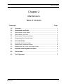
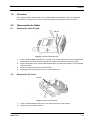
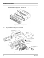
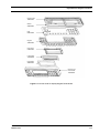
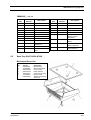
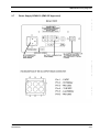
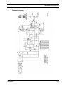
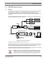
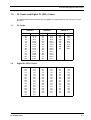
1
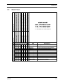
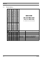
GM1200E
Mobile Radio
Basic Service Manual
68P64115B12
European Publications Department (RPG) Fleet, Hampshire, England
Issue: May 1998
ii
Cautions and Warnings
CAUTION
ELECTROSTATIC SENSITIVE DEVICES
PRECAUTIONS SHOULD BE TAKEN TO MINIMIZE THE RISK OF DAMAGE BY
ELECTROSTATIC DISCHARGE TO ELECTROSTATIC SENSITIVE DEVICES (ESDs).
ANY DEVICES EMPLOYING METAL OXIDE SILICON (MOS) TECHNOLOGY ARE
PARTICULARLY SUSCEPTIBLE.
CIRCUIT DIAGRAMS MARKED WITH THE ABOVE SYMBOL INDICATE ELECTRONIC
CIRCUITS (PECs) FOR WHICH ESD HANDLING PRECAUTIONS ARE NECESSARY.
THE USER SHOULD REFER TO BS5783, 1984: HANDLING OF ELECTROSTATIC
SENSITIVE DEVICES. THIS BRITISH STANDARD SUPERSEDES DEF STAN 59-98,
ISSUE 2.
iii
Cautions and Warnings
iv
Cautions and Warnings
WARNING
SAFETY WARNINGS
THE ELECTRICAL POWER USED IN THIS EQUIPMENT IS AT A VOLTAGE HIGH
ENOUGH TO ENDANGER LIFE.
BEFORE CARRYING OUT MAINTENANCE OR REPAIR, PERSONS CONCERNED
MUST ENSURE THAT THIS EQUIPMENT IS ISOLATED FROM THE ELECTRICAL
SUPPLY AND TESTS ARE MADE TO ENSURE THAT ISOLATION IS COMPLETE.
WHEN THE SUPPLY CANNOT BE ISOLATED, MAINTENANCE AND REPAIR MUST BE
UNDERTAKEN BY PERSONS WHO ARE FULLY AWARE OF THE DANGERS INVOLVED
AND WHO HAVE TAKEN ADEQUATE PRECAUTIONS TO PROTECT THEMSELVES.
COMPONENTS CONTAINING BERYLLIUM OXIDE ARE USED IN THIS EQUIPMENT.
DUST FROM THIS MATERIAL IS A HEALTH HAZARD IF INHALED OR ALLOWED TO
COME INTO CONTACT WITH THE SKIN.
GREAT CARE MUST BE TAKEN WHEN HANDLING THESE COMPONENTS WHICH
MUST NOT BE BROKEN OR SUBJECTED TO EXCESSIVE HEATING. DEFECTIVE
COMPONENTS MUST BE DISPOSED OF IN ACCORDANCE WITH CURRENT
INSTRUCTIONS.
LEAD ACID BATTERIES MAY BE FITTED AS THE STANDBY BATTERY. CARE MUST BE
TAKEN WHEN REMOVING OR INSTALLING THESE BATTERIES TO:
1. ENSURE THAT THE TERMINALS ARE NOT SHORTED TOGETHER.
2. PREVENT SPILLAGE OF THE CORROSIVE ELECTROLYTE.
v
Cautions and Warnings
vi
Contents
Basic Service Manual
Contents
Chapter
1.0
General
Gives a brief introduction into the manual; the service policy, models and
technical specifications.
2.0
Maintenance
Describes how to disassemble/assemble the radio for maintenance purposes
and provides lists of test equipment.
3.0
Accessories
Gives service details and provides a list of accessories available for the radio.
4.0
Radio Tuning Procedure
Provides detailed radio tuning procedure for all bands available.
Appendix
A.0
PL (CTCSS) / DPL Codes
B.0
External Device Connectors
C.0
Non Prescribed Data (NPD) Application Notes
Basic Service Manual
vii
Contents
viii
Basic Service Manual
Table of Contents
Chapter 1
General
Table of Contents
Paragraph
Page
1.0
Introduction ................................................................................................ 1
2.0
Scope of Manual ........................................................................................ 1
3.0
How to Use This Manual ............................................................................ 1
4.0
Warranty and Service Support ................................................................. 1
4.1
Warranty Period........................................................................................... 1
4.2
4.3
4.4
4.5
After Warranty Period ..................................................................................
Piece Parts ..................................................................................................
Technical Support........................................................................................
Associated Documentation ..........................................................................
5.0
Model Chart ................................................................................................ 3
5.1
Service Options ........................................................................................... 4
6.0
Technical Specifications ........................................................................... 5
6.1
6.2
6.3
6.4
General ........................................................................................................
Transmitter...................................................................................................
Receiver.......................................................................................................
Self-Quieting Frequencies ...........................................................................
General
2
2
2
2
5
5
6
6
1-i
Table of Contents
1-ii
General
Introduction
1
1.0
Introduction
This chapter outlines the scope and use of the basic service manual and provides an overview of
the warranty and service support.
2.0
Scope of Manual
This manual is intended for use by technicians familiar with similar types of equipment. It contains
levels 1 and 2 service information required for the equipment described and is current as of the
printing date. Changes which occur after the printing date maybe incorporated by a complete Basic
Service Manual revision to your Product Manual or alternatively as additionson a chapter basis.
3.0
How to Use This Manual
The basic service manual contains a general chapter giving information on warranty and support,
model charts and technical specifications. Chapters 2 and 3 contain level 1 and level 2 service
information for the radios and accessories respectively. Chapter 4 contains radio tuning procedures.
Refer to the Table of Contents for a general overview of the manual.
4.0
Warranty and Service Support
Motorola offers long term support for its products. This support includes full exchange and/or repair
of the product during the warranty period, and service/ repair or spare parts support out of warranty.
Any "return-for-exchange" or "return-for-repair" by an authorised Motorola Dealer must be
accompanied by a Warranty Claim Form. Warranty Claim Forms are obtained by contacting an
Authorised Motorola Dealer.
4.1
Warranty Period
The terms and conditions of warranty are defined fully in the Motorola Dealer or Distributor or
Reseller contract. These conditions may change from time to time and the following notes are for
guidance purposes only.
In instances where the product is covered under a "return for replacement" or "return for repair"
warranty, a check of the product should be performed prior to shipping the unit back to Motorola. To
ensure the product has been correctly programmed or has not been subjected to damage outside
the terms of the warranty.
Prior to shipping any radios back to the appropriate Motorola warranty depot, please contact
Customer Services. All returns must be accompanied by a Warranty Claim Form, available from
your Customer Services representative. Products should be shipped back in the original packaging,
or correctly packaged to ensure no damage occurs in transit.
General
1-1
Warranty and Service Support
4.2
After Warranty Period
After Warranty period, Motorola continues to support products in two ways.
Firstly, Motorola's Radio Parts and Service Group (RPSG) offer a repair service to both end users
and dealers at competitive prices.
Secondly, RPSG supplies individual parts and modules that can be purchased by dealers who are
technically capable of performing fault analysis and repair. To assist in this level of service, a
Detailed Service Manual containing level 3 repair information may be purchased separately.
4.3
Piece Parts
Some replacement parts, spare parts, and/or product information can be ordered directly. If a
complete Motorola part number is assigned to the part, it is available from Motorola Radio Parts and
Service Group (RPSG). If a generic part is listed or only a part description is listed, the part is not
normally available from Motorola. If a parts list is not included, this generally means that no userserviceable parts are available for that kit or assembly.
All orders for parts/information should include the complete Motorola identification number. All part
orders should be directed to your local RPSG office.
Head Office
Motorola G.m.b.H.
European Parts Department
65232 Taunusstein
Germany
4.4
Technical Support
Motorola Product Services is available to assist the dealer/distributors in resolving any malfunctions
which may be encountered. Initial contact should be by telephone whenever possible. When
contacting Motorola Technical Support, be prepared with the product model number and the unit’s
serial number.
4.5
1-2
Associated Documentation
Publication Number
Description
68P64115B15
GM1200E Detailed Service Manual (for Level 3 repair only)
68P64117B01
Shared Mobile Radio Systems (SMR) using MPT1327
A System Integrators Cookbook
68P02900X57-A
Data Application Notes for 1200 Series Radios
ELN4683A
1200 Series Product Manual
General
Model Chart
Description
GM1200E 403-470MHz 12.5kHz 25W DB
GM1200E 403-470MHz 25kHz 25W DB
GM1200E 403-470MHz 12.5kHz 25W KD
GM1200E 403-470MHz 25kHz 25W KD
GM1200E 136-174MHz 12.5kHz 25W DB
GM1200E 136-174MHz 25kHz 25W DB
GM1200E 136-174MHz 12.5kHz 25W KD
GM1200E 136-174MHz 25kHz 25W KD
M08RHA4CK5_N
M08RHA6CK5_N
M08RHH4CK6_N
M08RHH6CK6_N
M08KHA4CK5_N
M08KHA6CK5_N
M08KHH4CK6_N
M08KHH6CK6_N
Model Chart
Model
5.0
GM1200E
403-470 MHz UHF
136-174 MHz VHF
X = Indicates one of each required
Item
X
X
X
X
X
X
X
X
X
X
GCN6109_
Control Head Model K5 Blank
X
GCN6110_
Control Head Model K6 Keypad/Display
X
X
X
X
GMN6146_
Enhanced Compact Microphone
X
GLN7324_
Low Profile Trunnion Kit
GUE1124_
RF & HSG UHF 12.5kHz 5-25W
GUE1125_
RF & HSG UHF 25kHz 5-25W
GUD1326_
RF & HSG VHF 12.5kHz 5-25W
X
GUD1327_
RF & HSG VHF 25kHz 5-25W
X
X
GKN6270_
Power Cable
X
X
68P64110B08
GM1200E User Guide M/L
X
X
X
X
X
X
General
Packaging Kit
X
X
X
GBN6147_
X
X
X
X
X
X
X
X
Description
X
X
X
X
X
X
1-3
Model Chart
Description
GM1200E 403-470MHz 12.5kHz 25W DB
GM1200E 403-470MHz 25kHz 25W DB
GM1200E 403-470MHz 12.5kHz 25W KD
GM1200E 403-470MHz 25kHz 25W KD
GM1200E 136-174MHz 12.5kHz 25W DB
GM1200E 136-174MHz 25kHz 25W DB
GM1200E 136-174MHz 12.5kHz 25W KD
GM1200E 136-174MHz 25kHz 25W KD
M08RHA4CK5_N
M08RHA6CK5_N
M08RHH4CK6_N
M08RHH6CK6_N
M08KHA4CK5_N
M08KHA6CK5_N
M08KHH4CK6_N
M08KHH6CK6_N
Service Options
Model
5.1
GM1200E
403-470 MHz UHF
136-174 MHz VHF
X = Indicates one of each required
Item
X
X
X
X
X
X
X
X
1-4
Description
ENUD1061AS
GM1200E UHF 12.5kHz MD534AD
ENUD1062AS
GM1200E UHF 25kHz MD514AD
ENUD1063AS
GM1200E UHF 12.5kHz MD534AE
ENUD1064AS
GM1200E UHF 25kHz MD514AE
ENUE1071AS
GM1200E VHF 12.5kHz MD334AD
ENUE1072AS
GM1200E VHF 25kHz MD314AD
ENUE1073AS
GM1200E VHF 12.5kHz MD334AE
ENUE1074AS
GM1200E VHF 25kHz MD314AE
General
Technical Specifications
6.0
Technical Specifications
6.1
General
SPECIFICATION ITEM
Frequency Range
UHF: 403-470 MHz
VHF: 136-174 MHz
Channel Spacing
12.5 kHz or 20/25kHz
Frequency Stability
± 2ppm (UHF) / ± 5ppm (VHF)
Power Supply
10.8 to 15.6V dc, negative earth
Dimensions
K5 Model - 44x168x160 mm (HxWxD)
K6 Model - 55x185x167 mm (HxWxD)
Weight
1030g
Operational Temperature
- 25°C to + 55°C
Storage Temperature
- 40°C to + 85°C
Antenna Connection
50Ω BNC
Environmental
- Mechanical
- Electrical
6.2
TYPICAL VALUE
Vibration IEC 68/2/27 and Shock IEC 28/2/6
European Dust & Water protection IP54
ETS300-086
ETS300-113
ETS300-279
ETS300-219
Transmitter
SPECIFICATION ITEM
General
RF Specifications
Cyclic Keying Requirements
EMC Requirements
Signalling
TYPICAL VALUE
Channel Spacing
12.5kHz or 20/25kHz
Output Power
5-25W
Modulation Limiting
<± 2.5kHz (12.5kHz); <± 4kHz (20kHz);
<± 5kHz (25kHz)
FM hum & noise (CCITT)
>40dB (12.5kHz); >45dB (20/25kHz) CCITT
Conducted/Radiated Emission
<0.25µW (0.1...1000MHz); <1µW (1...4GHz)
Adjacent Channel Power
<-60dB (12.5kHz); <-70dB (20/25kHz)
Audio Response (300 - 3000 Hz)
Flat or pre-emphasised
Audio Distortion
<5% @ 1kHz, 60% deviation
Transmit turn on time
<25msec
1-5
Technical Specifications
6.3
Receiver
SPECIFICATION ITEM
6.4
TYPICAL VALUE
Channel Spacing
12.5kHz or 20/25kHz
Sensitivity @ 12.5kHz or 20/25kHz
< 0.35µV (12dB SINAD)
Intermodulation
>65dB ETS; >70dB with Base Option
Adjacent Channel Selectivity
>60dB (12.5kHz); >70dB (20/25kHz) ETS
Spurious Rejection
>70dB ETS
Audio Distortion @ Rated Audio
<5%
Hum and Noise (CCITT)
>40dB (12.5kHz); >45dB (20/25kHz) CCITT
Audio Response (300 - 3000 Hz)
Flat or De-Emphasised
Co-channel Rejection
<12dB (12.5kHz); <8dB (20/25kHz) ETS
Conducted /Radiated Emission
<2nW (0,1..1000MHz); <20nW (1..4GHz)
Receive after transmit time
<25msec
Audio Output Power
<13W external
Self-Quieting Frequencies
Self-quieting frequencies are frequencies that are also generated by the radio and cause internal
interference. On these frequencies the interference caused by the self-quieter spur is great enough
that a radio will not meet its receiver sensitivity specification.
The frequencies are:
1-6
UHF 403.2, 420, 436.8 and 453.6MHz.
VHF 151.2 and 168MHz.
General
Table of Contents
Chapter 2
Maintenance
Table of Contents
Paragraph
Page
1.0
Overview ..................................................................................................... 1
2.0
Disassemble the Radio ............................................................................. 1
2.1
2.2
2.3
2.4
Remove the Control Head ...........................................................................
Remove the Top Cover................................................................................
Remove the Transceiver Board ...................................................................
Disassemble the Control Head ....................................................................
3.0
Assemble Radio ......................................................................................... 4
3.1
3.2
3.3
Assemble the Control Head......................................................................... 4
Replace the Transceiver Board ................................................................... 4
Replace the Top Cover and Control Head................................................... 4
4.0
Exploded View Diagrams and Parts ......................................................... 5
5.0
Service Aids ............................................................................................... 7
6.0
Test Equipment .......................................................................................... 8
Maintenance
1
1
2
3
2-i
Table of Contents
2-ii
Maintenance
Overview
2
1.0
Overview
This chapter explains, step by step, how to disassemble and assemble the radio, to transceiver
board level. The chapter also contains a list of test equipment required to service the radio.
2.0
Disassemble the Radio
2.1
Remove the Control Head
Recess
Figure 2-1 Control Head Removal.
2.2
1.
Insert a small flat blade screw driver, or similar, in the recess between the control head and the
transceiver (to minimise cosmetic damage to the radio cover start from the bottom side).
2.
Press until the side of the control head releases and then repeat the operation on the opposite
side of the radio.
3.
Pull the control head away from the transceiver.
4.
Remove the flex from the socket on the control head board.
Remove the Top Cover
Recess
Figure 2-2 Top Cover Removal.
1.
Insert a small flat blade screw driver in the side recess of the radio chassis.
2.
Lift the top cover over the chassis.
Maintenance
2-1
Disassemble the Radio
2.3
Remove the Transceiver Board
Protruding Tabs
Flex
Clip
Recess
Clip
Recess
Chassis
Transceiver Board
Top Cover
Figure 2-3 Transceiver Board Removal.
1.
Remove the power and antenna connector retaining clips by inserting a small flat blade screw
driver between the clip and the top of the chassis wall and gently prying the clip upwards.
2.
Remove 13 screws from the transceiver board using a T8 TORX driver.
3.
Carefully remove the transceiver board by rotating it out of the chassis:
Slowly lift the board on the front edge, the side with the connector that mates with the control
head, and pull gently toward the front of the radio.
CAUTION:
2.4
2-2
The thermal grease can act as an adhesive and cause the leads of the heat
dissipating devises to be over stressed if the board is lifted too quickly.
Disassemble the Control Head
1.
To remove the printed circuit board from the control head front housing, first split control head
into front and rear housing. In the front housing, insert a small blade screw driver in the side
groove near the four protruding tabs of the printed circuit board. Remove the board from the
control head front housing.
2.
Remove the keypad from the control head housing by lifting up the rubber keypad. Care should
be taken not to touch or get other contaminates on the conductive pads on the under side of
the keypad or conductive contacts on the printed circuit board.
3.
Remove the LCD module fom the LCD frame attached to the PCB.
Maintenance
Assemble Radio
Control Head
Housing
LCD Module
Recess
Keypad
Recess
Protruding
Tabs
Printed
Circuit
Board
Control Head
Housing Back
LAPD0014
Figure 2-4 Control Head Assembly.
3.0
Assemble Radio
3.1
Assemble the Control Head
3.2
3.3
1.
Ensure that the LCD module and frame are correctly positioned on the PCB.
2.
Place the keypad onto the board assembly, making sure the keypad is flush with the board.
3.
During the installation of the printed circuit board, ensure the four protruding tabs snap into the
recesses.
Replace the Transceiver Board
1.
Inspect and if necessary, reapply thermal grease to the heatsinking pads in the chassis.
2.
Before installing the connector retaining clips, ensure that the board is sitting flush on the
chassis mounting surface.
3.
Install the 13 screws with 0.4 -07 NM (4-6 in lbs) of torque using a T8 TORX driver.
Replace the Top Cover and Control Head
1.
Position the top cover over the chassis and replace. Ensure that the cross snaps into the
recesses.
2.
Connect the control head to the radio by the flex.
Maintenance
2-3
Exploded View Diagrams and Parts
3.
Press the control head onto the radio chassis until the protruding tabs on the chassis snap into
the recesses inside the control housing, see Figure 2-5.
Recess
Figure 2-5 Control Head Replacement.
4.0
Exploded View Diagrams and Parts
Cover Chassis 1502609Y01
incl. Gasket Chassis
3202619Y01
Shield
2602640Y02
Screw M3x10
0310911A12
Shield
2602639Y01
Main
PCB
Accessory Conn. 16Pin
2804503J01
Controlhead K6
Power Conn. 0905902V04
Gasket 3205930V01
Flex
8402618Y01
Clip 4205938V01
Pad
7502618Y01
Gasket
Controlhead
3202620Y01
Connector 1580922V01
Antenna Conn.
0905901V02
incl. Gasket
3205929V01
Gasket Accessory Conn.
3202606Y01
Chassis
2702608Y02
Gasket Cover
3202607Y01
Figure 2-6 Radio Exploded View Diagram.
2-4
Maintenance
Exploded View Diagrams and Parts
Housing, back
1586001B01
Gasket
3286006B01
PCB
8486015B04
Keypad
7586002B01
LCD Frame
0786004B01
LCD Module
7286003B01
LCD Gasket
3286005B01
Housing, front
Control head
1586000B01
Figure 2-7 Control Head for Display/Keypad Radio Model.
Maintenance
2-5
Service Aids
5.0
Service Aids
The list in table 2-1 includes service aids recommended for working on the GM1200E radio.
Table 2-1 Service Aids.
PART No.
2-6
DESCRIPTION
APPLICATION
GTF376
Test Box Cable
Connects radio to GTF180 test box.
GTF374
Combined Interface
Cable
Connects radio to RLN4008 RIB.
GTF377
Combined Interface
Cable
Connects Databox radio to RLN4008 RIB.
GPN6133
Power Supply
Used to supply power to the radio.
GKN6266
DC Power Cable for radio
Interconnects radio to power supply.
GTF180
Test Box
Enables connection to the universal connector. Allows
switching for radio testing.
RLN4008
Radio Interface Box
Enables communications between the radio and the
computer’s serial communications adapter.
EPN4040
Power Supply
Used to supply power to the RIB (240 VAC).
EPN4041
Power Supply
Used to supply power to the RIB (220 VAC).
3080369B72
Computer Interface Cable
Connects the computer’s serial communications adapter
(9 pin) to the RIB.
3080369B71
Computer Interface Cable
Connects the computer’s serial communications adapter
(25 pin) to the RIB.
ENVN4001
MPT1327 1200E Series
DPS Dealer Software, 3.5” floppy disks.
ENVN4002
MPT1327 1200E Series
DPS Network Software, 3.5” floppy disks.
Maintenance
Test Equipment
6.0
Test Equipment
The list in table 2-2 includes all standard test equipment required for servicing two-way mobile
radios, as well as several unique items designed specifically for servicing the GM1200E radio.
Battery-operated test equipment is recommended when available. The “Characteristics” column is
included so that equivalent equipment may be substituted; however, when no information is provided
in this column, the specific Motorola model listed is either a unique item or no substitution is
recommended.
Table 2-2 Recommended Test Equipment.
MODEL No.
DESCRIPTION
CHARACTERISTICS
APPLICATION
This monitor will
substitute for items with
an asterisk (*)
Frequency/deviation meter
and signal generator for widerange troubleshooting and
alignment.
R2000 Series
System Analyser
*R1150C
Code Synthesizer
*S1053D
*HM-203-7
*SKN6008A
*SKN6001A
220 VAC Voltmeter
110 VAC Voltmeter
Power Cable for Meter
Test Leads for Meter
1mV to 300V, 10MΩ
Input impedance
Audio voltage measurements
*S1350C
*ST1213B (VHF)
*ST1223B (UHF)
Watt Meter
Plug-in Element
RF Dummy Load
50 ohm, ±5% accuracy
10 Watts, maximum
0-1000 MHz, 300W
Transmitter power o/p
measurements
R1065A
Load Resistor
10-watt Broadband
For use with Wattmeter
S1339A
RF Millivolt Meter
10kHz to 1.2 GHz
100µV to 3V RF
RF level measurements
*R1013A
SINAD Meter
S1347D or
S1348D
(programmable)
DC Power Supply
Injection of audio and digital
signalling codes
Receiver sensitivity
measurements
0-20Vdc, 0-5 Amps
Bench supply for 13.2Vdc
current limited
* Any of the R2000 Series system analysers will substitute for items with an asterisk (*)
Maintenance
2-7
Test Equipment
2-8
Maintenance
Table of Contents
Chapter 3
Accessories
Table of Contents
Paragraph
Page
1.0
GM1200E Accessory Connector Plan...................................................... 1
2.0
GM1200E Accessory Diagrams ................................................................ 2
2.1
2.2
2.7
2.8
Speaker GSN6059 5.5ins/130mm, 13 Watts............................................... 2
Handset HMN9416 (P/O HMN3141)
Mechanical Exploded View.......................................................................... 3
Enhanced Compact Microphone GMN6146
Mechanical Exploded View.......................................................................... 5
DTMF Microphone GMN6148
Mechanical Exploded View.......................................................................... 7
Base Tray GLN7318/GLN7326.................................................................. 11
Remote Mount Front / Rear Housing Kits GLN7331 / GLN7332
Mechanical Exploded View........................................................................ 12
Power Supply GPN6133 (EMC/CE Approved) .......................................... 13
Power Supply HPN8393 (Not EMC Approved).......................................... 14
3.0
List of Accessories.................................................................................. 16
2.3
2.4
2.5
2.6
Accessories
3-i
Table of Contents
3-ii
Accessories
GM1200E Accessory Connector Plan
3
1.0
GM1200E Accessory Connector Plan
CAUTION:
The accessory connections shown are not compatible to some other models of
Motorola radios. Check the appropriate accessory or technical manual for further
information.
+12V
86
87
85
30
Alternative
Alarm
Relay
+12V
4
+12V
86
87
85
30
Alternative
Alarm
Relay
+12V
4
CAUTION:
1. DO NOT short pin 1 or 16 on the accessory connector to ground, this may
damage the radio.
CAUTION:
Ensure correct position of the accessory connector.
Accessories
3-1
GM1200E Accessory Diagrams
2.0
GM1200E Accessory Diagrams
2.1
Speaker GSN6059 5.5ins/130mm, 13 Watts
130.0
130.0
100.0
55.0
1 + 16 connected
Cable
Length
2540 mm
135.0
30.0
80.0
3-2
Accessories
GM1200E Accessory Diagrams
2.2
Handset HMN9416 (P/O HMN3141)
Mechanical Exploded View
Mechanical Parts List
Ref
No.
1
2
3
4
5
6
7
8
9
10
Accessories
Motorola
Part No.
13-80928W01
15-82281R01
75-80927W01
30-06418T01
07-80148G02
15-84795P04
03-10908A91
03-10913B37
Description
Escutcheon
Top Housing
Top Housing Pad
Coil Cord Cable
Mic Cartridge (MK101)
Mic Gasket Bracket
Bottom Housing
Machine Screw
Tapping Screw
PTT Dome Switch (S11)
Ref
No.
11
12
13
14
15
16
17
18
19
20
Motorola
Part No.
38-84658P01
32-80272F16
03-10944A03
43-84312N01
01-80701Y77
75-80926W01
32-80282F02
61-80266F10
Description
PTT Button
Speaker (LS10)
Microphone Gasket
Not used
Tapping Screw
Reed Switch Spacer
Circuit Board Assembly
Circuit Board Pad
Lens Gasket
Display Lens
3-3
GM1200E Accessory Diagrams
2.2.1
Description
The HMN3141 Handset and hang-up cup is a slimline telephone handset with push to talk (PTT)
button. It is used in place of, and operates similar to, the standard mobile microphone.
2.2.2
Installation
General
When planning the installation of your handset, it is important that it does not interfere with the
operation of the vehicle or its accessories, nor disturb passenger seating or leg space. The handset
must be within convenient reach to the user. In general terms, the location of the handset should be
similar to the standard mobile microphone.
Adjustable Angle Bracket
3-4
1.
Verify that the selected mounting surface is strong enough to support the mounting hardware.
2.
Use the base of the adjustable angle bracket as a template, then centre punch and drill four
3.4mm diameter holes. Be careful not to damage any wires or other vital vehicle components
when drilling the holes.
3.
Use the four M4x20mm tapping screws and the internal star lockwashers to mount and
secure the bracket.
4.
Place the hang-up cup on top of the mounting surface of the mounting bracket and secure it
using the four M3.5x0.6x20mm machine screws, lockwashers, and hex nuts provided.
5.
Select the angle between the two bases of the adjustable angle bracket (from 0 to 110
degrees) and tighten the two adjusting screws.
Accessories
GM1200E Accessory Diagrams
2.3
Enhanced Compact Microphone GMN6146
Mechanical Exploded View
4
6
5
1
7
2
3
Mechanical Parts List
Ref
No.
1
2
3
4
Motorola
Part No.
0180704Y99
0311994A23
5480104R12
5480104R02
1580566B02
Description
Rear Housing assembly
Screw (3 used)
Model Label (GMN6146C)
Model Label (GMN6146B)
Front Housing
Ref
No.
5
6
7
Motorola
Part No.
3880568B01
7580983Z03
4180150R01
3280565B01
3002593Y02
Description
PTT Button
Rubber Spacer
Spring Tension
Gasket MIC
Coiled Cord
Hang-Up Clip Parts List
Ref
No.
9
10
Accessories
Motorola
Part No.
03-00139913
01-80743T91
Description
Screw, 8-18x1/2 (3 used)
Hang-up clip
3-5
GM1200E Accessory Diagrams
Schematic Diagram
Electrical Parts Lists
Circuit
Ref
3-6
Motorola
Part No.
Description
Circuit
Ref
Motorola
Part No.
Description
R1300
1805500L04
RES VAR 2.2k (not
used)
C1306
2113741A21
CAP CHIP CL2 X7R 1n
C1307
2113741A21
CAP CHIP CL2 X7R 1n
R1301
0660076A57
RES CHIP 2.2k 5 1/8
C1308
2311049J26
R1302
0660076A43
RES CHIP 560 5 1/8
CAP TANT CHIP 10uF
16V
R1303
0660076A65
RES CHIP 4.7k 5 1/8
C1309
2311049J26
R1304
0660076A43
RES CHIP 560 5 1/8
CAP TANT CHIP 10uF
16V
R1305
0660076B05
RES CHIP 150k 5 1/8
C1310
2113741A21
CAP CHIP CL2 X7R 1n
R1306
0660076B13
RES CHIP 330k 5 1/8
C1311
2113743F12
CER CHIP CAP 330n
R1307
0660076A75
RES CHIP 12k 5 1/8
C1314
2113741A21
CAP CHIP CL2 X7R 1n
R1308
0660076A47
RES CHIP 820 5 1/8
C1315
2113741A21
CAP CHIP CL2 X7R 1n
2113741A21
CAP CHIP CL2 X7R 1n
R1309
0660076A51
RES CHIP 1.2k 5 1/8
C1316
R1310
0660076A51
RES CHIP 1.2k 5 1/8
Q1301
4813824A10
XSTR NPN 40V .2A
Q1302
4813824A10
XSTR NPN 40V .2A
D1301
4880140L15
DIODE SOT ZENER
10V
D1302
4880140L07
DIODE SOT ZENER
5.6V
4080164S01
SWITCH,PTT
5080258E04
ELECTRET MIC CTRG
8402571Y01
PCB RENA MIC BLK
C1301
2113740A38
CAP CHIP CL1 24p
C1302
2113741A21
CAP CHIP CL2 X7R 1n
C1303
2113741A61
CAP CHIP CL2 X7R
47n
C1304
2113741A51
CAP CHIP CL2 X7R
18n
C1305
2113741A21
CAP CHIP CL2 X7R 1n
Accessories
GM1200E Accessory Diagrams
2.4
DTMF Microphone GMN6148
Mechanical Exploded View
Mechanical Parts List
Ref
No.
1
2
3
4
5
6
7
8
9
10
11
12
13
Accessories
Motorola
Part No.
15-80652D02
32-80565B01
75-80983Z03
38-80654D01
41-80658D01
35-80089D02
75-80655D01
01-80707Y77
42-80656D01
01-80707Y78
01C80669D01
54-80104R10
03-139959
Description
Microphone front housing
Microphone gasket
Rubber Spacer, Switch
Button, push to talk
Spring, PTT
Felt baffle
Keypad
DTMF Encoder board assy
Spacer
Switch/Sidetone board assy
Microphone rear Housing
Mic label
Screw, thread forming
1
abc 2
def 3
5
mno 6
ghi
4
j kl
prs
7
tuv 8
wxy
opr 0
#
9
3-7
GM1200E Accessory Diagrams
Schematic Diagram
3-8
Accessories
SW0
SHOWN FROM SOLDER SIDE
SW
SW
8402685Y01 GEPD 5470
DS10
SW9
SW8
SW7
DS11
SW6
SW5
DS13
SW3
SW4
DS12
SW2
C26
C1301
R42
U3
R43
R7
C17
R33
R12
R23
Q1
R11
U1
R32
C1302
CR1
Q1304
C1305
C20
R5
C3
C1306
R3
Q1303
VR1301
R20
R22
R15
C8
R14
C7
R21
C12
C11
C13
R24
8402685Y01 GEPD 5469
C1314
VR1302
Q2
R2
U5
C6
C9
C1308
C1313
U2
CR1301 R1307
C2
C19
R4
C1
R6 C5
R9
U4
R1309
Q1302 R1306 C1307
C1312
C1304
SHOWN FROM COMPONENT SIDE
C29
C16
Y1
C15
VR5
C23
C24
Q6
C18
R1308
SW1
C14
R44
R16
R1303
R10
C1310
R13
R1305
R1
R1310
C1309
R17
R1302
R19
C1311
R18
Accessories
C10
R40
GM1200E Accessory Diagrams
PCB Layout
3-9
GM1200E Accessory Diagrams
Electrical Parts List
GMN6148_
Circuit
Ref
3-10
Motorola
Part No.
Description
Circuit
Ref
Motorola
Part No.
Description
C1
23-11049A07
1uF; 16V, 10%, TANT
CR12
48-83636N18
LED; GREEN, SMD
C2
21-13740A73
560pF
CR13
48-83636N18
LED; GREEN, SMD
C3
23-11049A59
10uF; 6V,10%, TANT
CR1301
48-13833C04
BAV70LT1
C5
21-13740A59
150pF
Q1
4880214G02
MMBT 3904
C6
21-13741A45
0.01uF
Q2
4880214G02
MMBT 3904
C7
21-13741A45
0.01uF
Q6
4880214G02
MMBT 3904
C8
21-13741A45
0.01uF
Q1302
48-80214G02
MMBT 3904
C9
21-13740A59
150pF
Q1303
48-05128M19
MMBTA 13
C10
21-60521G37
0.1uF
Q1304
48-05128M16
MMBT 3906
C11
23-11049A07
1uF; TANT
R1
06-60076B01
100K
C13
21-13740A59
150pF
R2
06-60076B03
120K
C14
21-60521G37
0.1uF
R3
06-60076A87
39K
C15
21-13740A40
30pF
R4
06-60076A87
39K
C16
21-13740A40
30pF
R5
06-60076A73
10K
C17
23-11049A07
1uF; TANT
R6
06-60076B05
150K
C18
21-13741A45
0.01uF
R7
06-60076B25
1Meg
C19
21-13740A59
150pF
R9
06-60076B01
100K
C20
21-13741A45
0.01uF
R10
06-60076A73
10K
C23
23-11049A30
33uF, 6V, 10%, TANT
R11
06-60076B01
100K
C24
21-13740A79
1000pF
R12
06-60076A89
47K
C26
21-13740A79
1000pF
R13
06-60076A47
820
C29
23-11049A07
1uF; TANT
R14
06-60076A47
820
C1301
21-13740A39
27pF, 50V, NPO.
R15
06-60076A93
68K
C1302
21-13740A79
1000pF
R16
06-60076A73
10K
C1304
23-11049A59
10uF; 6V, 10%, TANT
R17
06-60076A87
39K
C1305
21-13743B23
0.330uF
R18
06-60076A89
47K
C1306
21-13740A59
150pF
R19
06-60076A73
10K
C1307
21-13740A79
1000pF
R20
06-60076A73
10K
C1308
21-11032B14
0.15uF
R21
06-60076B01
100K
C1309
21-13740A59
150pF
R22
06-60076A89
47K
C1310
21-13740A59
150pF
R23
06-60076A65
4.7K
C1311
21-13740A59
150pF
R24
06-60076A87
39K
C1312
21-13740A59
150pF
R32
18-60502A13
10K VAR; SMD
C1313
21-13740A59
150pF
R33
06-60076A63
3.9K
C1314
21-13741A45
0.01µF
R40
06-60076A65
4.7K
CR1
48-84336R03
MMBD 7000
R42
06-60076A84
30K
CR10
48-83636N18
LED; GREEN, SMD
R43
06-60076A84
30K
CR11
48-83636N18
LED; GREEN, SMD
R44
06-60076A25
100
Accessories
GM1200E Accessory Diagrams
GMN6148_ continued,
Circuit
Ref
2.5
Motorola
Part No.
Description
Circuit
Ref
Motorola
Part No.
Description
R1302
06-60076A57
2.2K; 5%, 1/8W
VR5
48-80140L05
4.7V; 5%, ZENER
R1303
06-60076A49
1K; 5%, 1/8W
VR1301
48-80140L17
12V; 5%, ZENER
R1305
06-60076B05
150K; 5%, 1/8W
VR1302
48-80140L17
12V; 5%, ZENER
R1306
06-60076M01
0; RES. JUMPER
Y1
48-80915W02
3.58 MHZ Resonator
R1307
06-60076B01
100K; 5%, 1/8W
Y2
50-80121L01
Transducer
R1308
06-60076A81
22K; 5%, 1/8W
50-13920A04
R1309
06-60076B01
100K; 5%, 1/8W
R1310
06-60076B01
100K; 5%, 1/8W
ADHESIVE, MIC
SHIELD, DTMF
ENCODER
SW1301
40-80164S01
SWITCH, PTT
30-02593Y02
COIL CORD W. IP54
BOOT
U1
51-80662D01
MK53731D DTMF
DIALER I.C.
84-02685Y01
Circuit Board
EURO DTMF MIC
U2
51-13819A02
LM2902D OPAMP
84-80661D01
U3 to
U5
51-80159R01
DUAL TRANSISTOR;
IMX1
Circuit Board,
Switch/sidetone
Base Tray GLN7318/GLN7326
Mechanical Parts List
Ref
No.
1
2
3
4
5
6
Accessories
Motorola
Part No.
1580155J02
7510606A06
0384725C09
4205722C02
1580154J02
7510606A13
5080085D03
Description
Base housing
Bumper RBR black
Screw 4.2x16
Clamp fastener
Cover base housing
Bumper black
Speaker (GLN7326)
Not shown
3-11
GM1200E Accessory Diagrams
2.6
Remote Mount Front / Rear Housing Kits GLN7331 / GLN7332
Mechanical Exploded View
GLN7331_
Remote Front Housing
Remote
mount
radio
Front housing PCB
GLN7333
Pad
7586011B01
External spe
connector
Remote mount
Radio front housing
1586010B01
Gasket for
Remote cable so
3205789W01
Flex connector
0902636Y01
Gasket
3205789W01
Remote cable
HKN6097 3m (3005825X02)
HKN6098 5m (3005825X01)
HKN6099 7m (3005825X03)
Remote Controlhead
back housing
1586012B01
Flex connector
interface
8402680Y02
External speaker
connector
Gasket for
Remote cable socket
3205789W01
Flex connector
0902636Y01
Remote Controlhead
back housing
1586012B01
Flex connector
interface
8402680Y02
5X02)
5X01)
5X03)
Controlhead
PCB
Controlhead
3-12
Gasket
Controlhead
3202620Y01
Remote mount
Bracket
0702457Y02
GLN7332_
Remote Back Housing
Accessories
GM1200E Accessory Diagrams
2.7
Power Supply GPN6133 (EMC/CE Approved)
Accessories
3-13
GM1200E Accessory Diagrams
2.8
Power Supply HPN8393 (Not EMC Approved)
Electrical Characteristics
Input Voltages:
105-125VAC; 210-250VAC, 47-63Hz
Output Voltage:
13.8VDC ±0.1 volts
(internally adjustable 11-15VDC)
Ripple:
less than 5mV peak to peak
(full load and low line)
Provides 8 amps continuous duty and 14 amps intermittent duty over an ambient temperature range
of -30 to +60°C .
(4 Pos) Positions 1 and 2 are positive power output terminals and positions 3 and 4 are for negative power output terminals for 14 amp max. current.
(6 Pos) Position 1 is negative power output terminal for 3 amp max current. Positions 2,3,6 are empty. Position
4 is positive 13.8VDC power output terminal. Position 5 is positive trickle charge output terminal.
3-14
Accessories
GM1200E Accessory Diagrams
Schematic Diagram
Accessories
3-15
List of Accessories
3.0
List of Accessories
Mechanical Hardware Kits:
GLN7324
GLN7317
GLN7320
GLN7325
HLN9457
Low Profile Trunnion Kit (Standard)
High Profile Trunnion Kit
In-Dash Mount, DIN install. Kit
IP54 seal, accessory connector
Accessory Connector Facility Kit
Microphones:
GMN6146
GMN6148
HMN3141
HMN3000
Enhanced Compact Microphone (Standard)
DTMF Microphone
Handset with Hang-up cup
Desk Microphone
Speakers:
Speaker connecting cables are provided with a 16-pin accessory connector plug.
GSN6059
13 W External Speaker, square
Cables:
GKN6270
GKN6271
ENKN4000
Battery power cable 3m, 10A fuse (Standard)
Ignition switch cable
MAP27 Interface Cable
Other
GKN6272
GLN7323
GLN7326
GPN6126
GPN6127
GPN6133
HPN4002
HPN8393
3-16
Alarm, Relay and Cable Kit
External PTT
Base Tray (with internal speaker)
24/12V DC Converter, 6A
24/12V DC Converter, 15A
EMC approved Power Supply
Non-EMC approved Power Supply
Non-EMC approved Power Supply
Accessories
Table of Contents
Chapter 4
Radio Tuning Procedure
Table of Contents
Paragraph
Page
1.0
GM1200E Tuning Procedure...................................................................... 1
1.1
1.2
1.3
1.4
1.5
1.6
1.7
1.8
1.9
1.10
1.11
1.12
General ........................................................................................................
PA Bias Voltage...........................................................................................
Battery Threshold ........................................................................................
Transmitter Power .......................................................................................
Reference Oscillator ....................................................................................
Front-End Pre-Selector................................................................................
Rated Volume ..............................................................................................
Squelch........................................................................................................
Transmit Voltage Limit .................................................................................
Transmit Deviation Balance (Compensation) ..............................................
Transmit Deviation Limit ..............................................................................
Signalling Alignments ..................................................................................
Radio Tuning Procedure
1
2
3
3
4
4
5
6
6
6
7
7
4-i
Table of Contents
4-ii
Radio Tuning Procedure
GM1200E Tuning Procedure
4
1.0
GM1200E Tuning Procedure
1.1
General
The recommended hardware platform is a 386 or 486 DX 33 PC (personal computer) with 8 Mbytes
RAM, MS DOS 5.0™, Windows 3.1™, and DPS (Dealer Programming Software). These are
required to align the radio. Refer to your DPS Installation Manual for installation and setup
procedures for the required software; the user manual is accessed (and can be printed if required)
via the DPS.
To perform the alignment procedures, the radio must be connected to the PC, RIB (Radio Interface
Box), and Universal Test Set as shown in figure 4-1.
30 dB PAD
SERVICE MONITOR
OR COUNTER
30 dB PAD
WATTMETER
TRANSMIT
BNC
RF GENERATOR
SMA-BNC
58-80348B33
RECEIVE
AUDIO IN
MIC IN
TX
AUDIO GENERATOR
TEST SET
RTX4005/
GTF180
RADIO
RX
TEST CABLE
GTF-376
SINAD METER
AC VOLTMETER
Note: Battery can be used in RIB
making power supply optional
25PIN
PROGRAM/TEST CABLE
GTF377 (Databox Radios only)
or GTF374
COMPUTER
15PIN
DATA
RIB
RLN-4008B
GND
COMPUTER INTERFACE CABLE
30-80369B72 (IBM "AT" 9PIN ONLY)
30-80369B71 (IBM "XT" 25PIN ONLY)
RIB POWER SUPPLY
EPN4041 (230 VAC. Euro)/
EPN4040 (230 VAC. UK)
Figure 4-1 Radio Alignment Test Setup
All tuning procedures are performed from the Service menu.
Before going into the Service menu, the radio must first be read using the File / Read Radio menu (if
the radio has just been programmed with data loaded from disk or from a newly created codeplug,
then it must still be read so that the DPS will have the radio’s actual tuning values).
All Service windows read and program the radio codeplug directly; you do NOT have to use the DPS
Read Radio / Write Radio functions to program new tuning values.
CAUTION:
Radio Tuning Procedure
DO NOT switch radios in the middle of any Service procedure. Always use the
Program or Cancel key to close the tuning window before disconnecting the radio.
Improper exits from the Service window may leave the radio in an improperly
configured state and result in seriously degraded radio or system performance.
4-1
GM1200E Tuning Procedure
The Service windows introduce the concept of the “Softpot”, an analog SOFTware controlled
POTentiometer used for adjusting all transceiver alignment controls. A softpot can be selected by
clicking with the mouse at the value or the slider or by hitting the TAB key until the value or the slider
is highlighted.
Each Service window provides the capability to increase or decrease the ‘softpot’ value with the
mouse, the arrow keys or by entering a value with the keyboard. The window displays the minimum,
maximum, and step value of the softpot. In addition transmitter tuning windows indicate the
transmitter frequency and whether the radio is keyed.
Adjusting the softpot value sends information to the radio to increase (or decrease) a DC voltage in
the corresponding circuit. For example, increasing the value in the Reference Oscillator tune window
instructs the radio microprocessor to increases the voltage across a varactor in the reference
oscillator to increase the frequency. Pressing the Program button stores all the softpot values of the
current window permanently in the radio.
In ALL cases, the softpot value is just a relative number corresponding to a D/A (Digital-to-Analog)
generated voltage in the radio. All standard measurement procedures and test equipment are
similar to previous radios.
Refer to the DPS on-line help for information on the tuning software.
Perform the following procedures in the sequence indicated.
Note:
1.2
All tuning procedures must be performed at a supply voltage of 13.2V unless otherwise
stated.
The Modulation Analyzer to measure the deviation should be set to frequency modulation
with de-emphasis switched off and all high pass filters switched off.
PA Bias Voltage
Adjustment of the PA Bias is critical for proper radio operation. Improper adjustment will result in
poor operation and may damage the PA FET device. For this reason, the PA bias must be set before
the transmitter is keyed the first time.
Note:
4-2
For certain radio models there are two bias voltage settings. For these radios both ‘ Bias 1
Voltage ’ and ‘ Bias 2 Voltage ‘ need to be adjusted when aligning the PA Bias. For models
that only have one bias voltage setting, the ‘ Bias 2 Voltage ‘ will be shown in grey on the
service menu.
1.
From the Service menu, select Transmitter Alignment.
2.
Select Bias Voltage Tuning to open the bias voltage tuning window. If the control voltage is out
of range, an error message will be displayed. In this case the radio hardware has a problem
and tuning must be stopped immediately.
3.
Click the button labelled “0” to set the quiescent current temporarily to 0 mA
4.
Measure the DC current of the radio. Note the measured value and add the specified quiescent
current shown in table 4-1. The result is the tuning target.
5.
Adjust the current per the target calculated in step 4.
6.
Click the Program button to store the softpot value.
Radio Tuning Procedure
GM1200E Tuning Procedure
Table 4-1 Quiescent Current Alignment
1.3
RF-Band
Target
UHF
VHF / 300-390MHz
440mA±10%
150mA±15%
Battery Threshold
The radio uses 2 battery threshold levels Tx High and Tx Low to determine the battery condition.
The Program buttons must only be activated when the power supply is set to the indicated voltage. If
the DPS detects that the voltage is not within the expected range for the threshold in question then a
message will be displayed to warn that the radio may not be set up correctly for the alignment
operation.
CAUTION:
1.4
Inadvertant use of the program buttons may result in radio failure.
1.
From the Service menu, select Transmitter Alignment.
2.
Select Battery Threshold to open the battery threshold tuning window. The current softpot
values are displayed for information only and cannot be edited.
3.
Set the supply voltage to the value indicated for TX High.
4.
Click the TX High Program button to store the softpot value for TX High.
5.
Set the supply voltage to the value indicated for TX Low.
6.
Click the TX Low Program button to store the softpot value for TX Low.
7.
Close the window by clicking Cancel.
Transmitter Power
The radio has two power level settings, a high power level setting, and a low power level setting.
IMPORTANT: To set the transmitter power for customer applications use the Common Radio
Parameters window under the Edit menu and set the “Low Power Level” and “High Power Level”
powers to the desired values. Only if the transmitter components have been changed or the
transmitter does not transmit with the power set in the Common Radio Parameters window the
following procedure should be performed.
CAUTION:
When setting the Transmitter Power DO
RECOMMENDED POWER SET LIMITS of 25W.
NOT
EXCEED
THE
The advanced power setting technology employed in the radio makes use of two reference power
level settings along with parameters describing the circuit behaviour. To determine these parameters
the DPS requires the power values measured for two different settings.
Radio Tuning Procedure
4-3
GM1200E Tuning Procedure
1.
From the Service menu, select Transmitter Alignment.
2.
Select RF Power Tuning to open the RF power tuning window. The window will indicate the
transmit test frequencies to be used.
3.
Select Point 1 value of the first frequency.
4.
Click Toggle PTT to key the radio. The status bar will indicate that the radio is transmitting.
5.
Measure the transmitter power on your power meter.
6.
Enter the measured value in the box Point 1.
7.
Select Point 2 value of the first frequency.
8.
Measure the transmitter power on your power meter.
9.
Enter the measured value in the box Point 2.
10. Click Toggle PTT to dekey the radio.
11. Repeat steps 3 - 10 for all test frequencies shown in the window.
12. Click Program to store the softpot values.
1.5
Reference Oscillator
Adjustment of the reference oscillator is critical for proper radio operation. Improper adjustment will
not only result in poor operation, but also a misaligned radio that will interfere with other users
operating on adjacent channels. For this reason, the reference oscillator should be checked every
time the radio is serviced. The frequency counter used for this procedure must have a stability of 0.1
ppm (or better).
1.
From the Service menu, select Transmitter Alignment.
2.
Select Reference Oscillator to open the reference oscillator tuning window. The tuning window
will indicate the target transmit frequency.
3.
Click Toggle PTT to key the radio. The status bar will indicate that the radio is transmitting.
4.
Measure the transmit frequency on your frequency counter.
5.
Adjust the reference oscillator softpot in the tuning window to achieve a transmit frequency
within the limits shown in table 4-2.
6.
Click Toggle PTT again to dekey the radio and then press Program to store the softpot value.
Table 4-2 Reference Oscillator Alignment
1.6
RF-Band
Target
All bands
±150 Hz
Front-End Pre-Selector
Alignment of the front-end pre-selector is normally not required on these radios. Only if the radio has
poor receiver sensitivity or the pre-selector parts has been replaced the following procedure should
be performed. The softpot value sets the control voltage of the pre-selector. Its value needs to be set
at 7 frequencies across the frequency range.
4-4
1.
Set the test box (GTF180) meter selection switch to the "Audio PA" position and connect a
SINAD meter to the "METER" port.
2.
From the Service menu, select Receiver Alignment.
3.
Select Front End Filter to open the pre-selector tuning window. The window will indicate the
receive test frequencies to be used.
Radio Tuning Procedure
GM1200E Tuning Procedure
4.
Select the first test frequency shown, and set the corresponding value to the start value shown
in table 4-4.
5.
Set the RF test generator to the receive test frequency, and set the RF level to 10µV modulated
with a 1 kHz tone at the normal test deviation shown in table 4-3.
6.
Measure the RSSI voltage at accessory connector pin 15 with a dc voltmeter capable of 1 mV
resolution.
7.
Change the softpot value by the stepsize shown in table 4-4 and note the RSSI voltage.The
target softpot value is achieved when the measured RSSI voltage change between step 6 and
step 7 is lower than the tuning target for the first time. The tuning target, shown in table 4-4, is
expressed as the percentage of the measured RSSI voltage and must be recalculated for every
tuning step. If the measured RSSI voltage decreases before the target value has been
achieved, approximation should be stopped and the current softpot value should be used as
target value. Set test box (GTF180) audio switch to the “SPKR” position. The 1 kHz tone must
be audible at the target value to make sure the radio is receiving.
8.
Repeat steps 4 - 7 for all test frequencies shown in the window.
9.
Click the Program button to store the softpot values.
Table 4-3 Normal Test Deviation.
Channel Spacing
Deviation
12.5 kHz
20 kHz
25 kHz
1.5 kHz
2.4 kHz
3 kHz
Table 4-4 Start Value for Front-End Pre-selector Tuning.
1.7
RF-Band
Target
Stepsize
Start Value
UHF
VHF
300-350MHz
336-390MHz
0.42%
0.5%
0.84%
0.31%
-2
+2
-2
-2
Maximum
Minimum
Maximum
Maximum
Rated Volume
The rated volume softpot sets the volume at normal test modulation.
1.
Set test box (GTF180) meter selection switch to the “AUDIO PA” position and the speaker load
switch to the "MAXAR" position. Connect an AC voltmeter to the test box meter port.
2.
From the Service menu, select Receiver Alignment.
3.
Select Rated Volume to open the rated volume tuning window. The screen will indicate the
receive test frequency to be used.
4.
Set the RF test generator to the receive test frequency, and set the RF level to 1mVolt
modulated with a 1 kHz tone at the normal test deviation shown in table 4-3. Set test box
(GTF180) audio switch to the “SPKR” position. The 1 kHz tone must be audible to make sure
the radio is receiving.
5.
Adjust the value of the softpot to obtain rated audio volume (as close to 3.87 Vrms).
Note:
6.
The voltage at the meter port of the testbox GTF180 is only half the voltage at the speaker.
Click the Program button to store the softpot value.
Radio Tuning Procedure
4-5
GM1200E Tuning Procedure
1.8
Squelch
The squelch softpots set the signal to noise ratio at which the squelch opens. The squelch value
needs to be set at 7 frequencies across the frequency range.
1.9
1.
Set the test box (GTF180) meter selection switch to the "Audio PA" position and connect a
SINAD meter to the "METER" port.
2.
From the Service menu, select Receiver Alignment.
3.
Select Squelch Attenuation to open the squelch attenuation tuning window. The window will
indicate the receive test frequencies to be used.
4.
Select the first test frequency shown, and set the corresponding value to 0.
5.
Set the RF test generator to the test frequency and modulate the signal generator at the normal
test deviation shown in table 4-3, with 1 kHz tone. Adjust the generator for a 8-10 dB SINAD
level (weighted with psophometric filter).
6.
Adjust the softpot value until the squelch just closes.
7.
Monitor for squelch chatter; if chatter is present, repeat step 6.
8.
When no chatter is detected, select the next softpot and repeat steps 4 - 7 for all test
frequencies shown in the window.
9.
Click the Program button to store the softpot values.
Transmit Voltage Limit
The transmit control voltage limit softpot sets the maximum power control voltage. All 7 voltage limit
softpots are tuned and programmed automatically when the Program button is clicked.
1.10
1.
From the Service menu, select Transmitter Alignment.
2.
Select Voltage Limit to open the voltage limit tuning window.
3.
Set the Power Factor to 1.3.
4.
Click the Program button to store the softpot values.
Transmit Deviation Balance (Compensation)
Compensation alignment balances the modulation sensitivity of the VCO and reference modulation
(synthesiser low frequency port) lines. Compensation algorithm is critical to the operation of
signalling schemes that have very low frequency components (e.g. DPL) and could result in
distorted waveforms if improperly adjusted. The compensation value needs to be set at 7
frequencies across the frequency range.
4-6
1.
From the Service menu, select Transmitter Alignment.
2.
Select Modulation Attenuation to open the deviation balance tuning window. The window will
indicate the transmit test frequencies to be used.
3.
Set the Test Box (GTF180) meter selector switch to the “GEN” position, and inject a 80 Hz tone
at 200 mVrms into the "Audio In" port. (The deviation measured at step 6 should be about
1-4kHz.) Connect an AC meter to the meter port to insure the proper input signal level.
4.
Select the first test frequency shown in the window.
5.
Click Toggle PTT to key the radio. The status bar will indicate that the radio is transmitting.
6.
Measure the transmitter deviation.
Radio Tuning Procedure
GM1200E Tuning Procedure
7.
Change the input tone to 3 kHz, 200 mVrms.
8.
Adjust the deviation to within ±2% of the value recorded in step 6.
9.
Check the deviation at 80 Hz again and repeat step 7-8, if it has changed since step 6.
10. Click the Toggle PTT to dekey the radio.
11. Repeat steps 3 - 10 for the remaining test frequencies.
12. Click the Program button to store the softpot values.
Note:
1.11
The step size change for step 8 is approximately 2.5% softpot value.
Transmit Deviation Limit
The transmit deviation limit softpot sets the maximum deviation of the carrier. The deviation value
needs to be set at 7 frequencies across the frequency range.
1.
From the Service menu, select Transmitter Alignment.
2.
Select Reference Attenuation to open the reference attenuation tuning window.
3.
Set the maximum value and press Program to store the softpot value.
4.
From the Service menu, select Transmitter Alignment.
5.
Select VCO Attenuation to open the deviation limit tuning window. The window will indicate the
transmit test frequencies to be used.
6.
Set the Test Box (GTF180) meter selector switch to the “GEN” position, and inject a 1 kHz tone
at 800 mVrms into the "Audio In" port. Connect an AC meter to the meter port to ensure the
proper input signal level.
7.
Select the first test frequency shown in the window.
8.
Click the Toggle PTT to key the radio. The status bar will indicate that the radio is transmitting.
9.
Adjust the transmitter deviation to the value shown in table 4-5.
10. Click the Toggle PTT to dekey the radio.
11. Repeat steps 8 - 10 for the remaining test frequencies.
12. Click the Program button to store the softpot values.
Table 4-5 Transmitter Deviation
1.12
Signalling Alignments
1.12.1
MPT RSSI Threshold Level
Channel Spacing
Deviation
12.5 kHz
2.2-2.3 kHz
20 kHz
3.4-3.6 kHz
25 kHz
4.3-4.6 kHz
The Program buttons must only be activated when the required signal is input to the radio and the
radio is receiving. If the DPS detects that the input signal is not within the expected range for the
RSSI level in question then a message will be displayed to warn that the radio may not be set up
correctly for the alignment operation.
Radio Tuning Procedure
4-7
GM1200E Tuning Procedure
CAUTION:
1.12.2
Inadvertant use of the program buttons may result in radio failure.
1.
Set test box (GTF180) meter selection switch to the “AUDIO PA” position and the speaker load
switch to the "MAXAR" position.
2.
From the Service menu, select Receiver Alignment.
3.
Select RSSI to open the RSSI tuning window. The screen will indicate the receive test
frequency to be used.
The softpot values are displayed for information only and cannot be edited.
4.
Set the RF test generator to the receive test frequency, and set the RF level to the value
indicated for RSSI Level 0, modulated with a 1 kHz tone at the normal test deviation shown in
table 4-3. Set test box (GTF180) audio switch to the “SPKR” position. The 1 kHz tone must be
audible to make sure the radio is receiving.
5.
Click the Program button to store the softpot value for RSSI Level 0.
6.
Repeat steps 4 - 5 for the remaining RSSI levels.
7.
Click the Cancel button to close the window.
MPT1327 Transmit Deviation / DTMF Transmit Deviation
The MPT1327 Deviation Softpot is used to tune the FFSK signalling deviation. Tuning is performed
at one frequency. The radio generates an alternating bit pattern for tuning. Values for other
frequencies are calculated by the radio software.
The DTMF Deviation Softpot is used to tune the DTMF signalling deviation. Tuning is performed at
one frequency. The radio generates a DTMF signal for tuning. Values for other frequencies are
calculated by the radio software.
1.
From the Service menu, select Transmitter Alignment.
2.
Select Signalling Deviation to open the signalling deviation tuning window.
3.
Select the MPT value and click the Toggle PTT to key the radio. The status bar will indicate that
the radio is transmitting.
4.
Adjust the transmitter deviation to the value shown in table 4-6.
5.
Click the Toggle PTT to dekey the radio.
6.
Repeat steps 3 - 5 for DTMF deviation.
7.
Click the Program button to store the softpot value.
Table 4-6 Signalling Deviation
4-8
Channel Spacing
MPT 1327
Deviation
12.5 kHz
1.4-1.6 kHz
1.5-1.8 kHz
20 kHz
2.2-2.6 kHz
2.4-2.8 kHz
25 kHz
2.8-3.2 kHz
3.0-3.4 kHz
Radio Tuning Procedure
Table of Contents
Appendix A
PL/DPL Codes
Table of Contents
Paragraph
Page
1.0
PL Codes and Digital PL (DPL) Codes . . . . . . . . . . . . . . . . . . . . . . . . . . . . 1
1.1
1.2
PL Codes. . . . . . . . . . . . . . . . . . . . . . . . . . . . . . . . . . . . . . . . . . . . . . . . . . . . . 1
Digital PL (DPL) Codes . . . . . . . . . . . . . . . . . . . . . . . . . . . . . . . . . . . . . . . . . . 1
PL (CTCSS) Codes
A-i
Table of Contents
A-ii
PL (CTCSS) Codes
PL Codes and Digital PL (DPL) Codes
1.0
PL Codes and Digital PL (DPL) Codes
The following have been tested and are acceptable for programming into any transmit or receive
frequency.
1.1
PL Codes
GROUP A
1.2
GROUP B
GROUP C
Code
Freq
Code
Freq
Code
Freq
XZ
XB
YB
1Z
1B
2A
3Z
3B
4A
5Z
6A
7Z
M1
M3
67.0
77.0
88.5
100.0
107.2
114.8
123.0
131.8
141.3
151.4
173.8
186.2
203.5
218.1
XA
YZ
ZA
1A
2Z
2B
3A
4Z
4B
5A
6Z
6B
7A
M2
71.9
82.5
94.8
103.5
110.0
118.8
127.3
136.5
146.2
156.7
167.9
179.9
192.8
210.7
WZ
WA
WB
YA
ZZ
ZB
5B
8Z
69.3
74.4
79.7
85.4
91.5
97.4
162.2
206.5
026
051
073
125
152
174
243
255
274
332
365
431
455
506
565
632
723
031
053
074
131
155
205
244
261
306
343
371
432
462
516
606
654
731
032
054
114
132
156
212
245
263
311
346
411
445
464
523
612
662
732
036
065
115
134
162
223
246
265
315
351
412
446
465
526
624
664
734
Digital PL (DPL) Codes:
023
043
071
116
143
165
225
251
266
325
356
413
452
466
532
627
703
743
PL (CTCSS) Codes
025
047
072
122
145
172
226
252
271
331
364
423
454
503
546
631
712
754
A-1
PL Codes and Digital PL (DPL) Codes
A-2
PL (CTCSS) Codes
Table of Contents
Appendix B
NPD Application Notes
Table of Contents
Paragraph
Page
1.0
Non Prescribed Data (NPD) Calls............................................................. 1
2.0
Calls with DTE connected to External Data Connector
(Radio Accessory Connector) .................................................................. 1
2.1
2.2
DTE Initiated Call (Outgoing Calls).............................................................. 1
Calls Initiated by another Radio Unit (Incoming Calls) ................................ 1
3.0
Calls with DTE connected to Internal Data Connector
(Radio Option Connector)......................................................................... 1
3.1
3.2
DTE Initiated Call (Outgoing Calls).............................................................. 1
Calls Initiated by another Radio Unit (Incoming Calls) ................................ 2
4.0
Other Calls.................................................................................................. 2
4.1
4.2
4.3
Voice Calls................................................................................................... 2
Status Calls.................................................................................................. 2
Mixed Calls .................................................................................................. 2
NPD Application Notes
B-i
Table of Contents
B-ii
NPD Application Notes
Non Prescribed Data (NPD) Calls
1.0
Non Prescribed Data (NPD) Calls
Non Prescribed Data calls utilising external Data Terminal Equipment (DTE) can be made using the
GM1200E Databox radio as the carrier.
Call protocol is by a combination of control line handshakes, the complexity of which depends on the
intelligence of the DTE.
2.0
Calls with DTE connected to External Data Connector
(Radio Accessory Connector)
2.1
DTE Initiated Call (Outgoing Calls)
■
■
■
■
2.2
Call set-up is initiated on ‘Call 1’ which should be programmed with an address including the
‘Non Prescribed Data’ (NPD) call modifier (*31*).
When the traffic channel data path is set up, the radio will enable the audio input and output
lines (with the microphone and loudspeaker lines disabled) and then signal that the DTE is
Clear to Send (CTS).
The DTE will send and receive audio signals using the PTT line as direction control.
Call clear can be from either DTE or radio.
DTE will remove the signal from ‘Call 1’ or signal on ‘Call Clear’.
Radio will remove the CTS line signal.
Calls Initiated by another Radio Unit (Incoming Calls)
■
■
■
Incoming calls will be indicated by a signal on the CTS.
The call will be “answered” by the DTE signalling on ‘Call 1’.
The call will continue and clear as described above in section 2.1
3.0
Calls with DTE connected to Internal Data Connector
(Radio Option Connector)
3.1
DTE Initiated Call (Outgoing Calls)
It is possible for the radio to call up to 3 different destinations (addresses) by using a combination of
Call 1 and Call 2 lines to signal one of three possibilities (Call N).
■
■
■
■
Call set-up is initiated on ‘Call N’ which should be programmed with an address including the
‘Non Prescribed Data’ (NPD) call modifier (*31*).
When the traffic channel data path is set up, the radio will enable the audio input and output
lines (with the microphone and loudspeaker lines disabled) and then signal that the DTE is
Clear to Send (CTS).
The DTE will send and receive audio signals using the PTT line as direction control.
Call clear can be from either DTE or radio.
DTE will remove the signal from ‘Call N’ or signal on ‘Call Clear’.
Radio will remove the CTS line signal.
NPD Application Notes
B-1
Other Calls
3.2
Calls Initiated by another Radio Unit (Incoming Calls)
■
■
■
Incoming calls will be indicated by a signal on the CTS.
The call will be “answered” by the DTE signalling on ‘Call 3’ (i.e.Call 1 and Call 2 lines both
enabled).
The call will continue and clear as described above in section 3.1
4.0
Other Calls
4.1
Voice Calls
It is possible to set up voice calls internally or externally using the procedures described above by
omitting the NPD call modifier from the called address. In this case the audio paths will be set up to
use the external microphone and loudspeaker with the volume pre-set. It is not possible to adjust the
volume from inside the radio.
4.2
Status Calls
It is possible to signal status calls internally or externally.
■
■
■
4.3
Status is sent by signalling on ‘Call N’ to a pre-set address using the Status call modifier.
The radio will send the pre-set status call to the pre-programmed address.
Call “success” will be signalled with a pulse on the CTS line.
Mixed Calls
Due to the ambiguity necessarily introduced by the very simple handshaking techniques employed,
users should only consider mixing Data/Voice/Status calls if they are confident that their DTE is
capable of correctly interpreting the handshakes under all conditions for all incoming and outgoing
call types likely to be encountered.
B-2
NPD Application Notes