
1
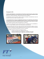
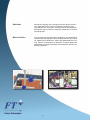
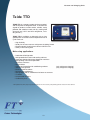
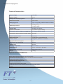
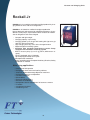
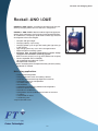
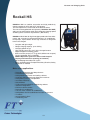
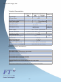
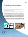
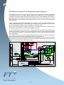
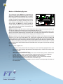
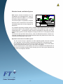
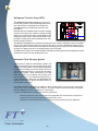
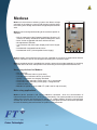
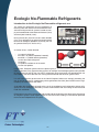
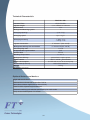
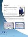
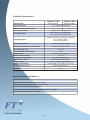
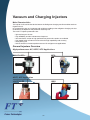
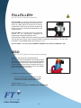
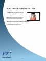
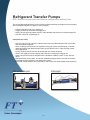
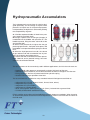
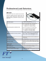
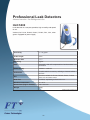
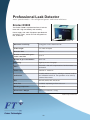
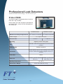
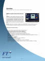
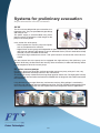
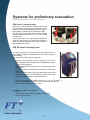
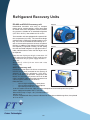
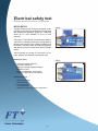
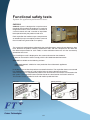
Master Catalog
2015/2016
Via delle Sorgenti, 5
58033 Castel del Piano GR ITALY
tel:
FAX:
email:
internet:
+39 0564 957385
+39 0564 957397
[email protected]
www.ftonweb.com
Main Index
Page 7
Page 9
Page 11
Page 13
Page 15
Page 17
Page 19
Page 21
Page 23
Page 29
Page 31
Page 33
Page 35
Page 37
Page 39
Page 41
Page 45
Page 47
Page 49
Page 50
Page 51
Page 52
Page 53
Page 55
Page 57
Page 58
Page 59
Page 61
Page 62
Page 63
Company Profile
Main Customers References
Vacuum and Charging units
Vacuum and Charging Unit Teide TTD
Vacuum and Charging Unit Rockall Jr
Vacuum and Charging Unit Rockall
Vacuum and Charging Unit Rockall HS
Vacuum and Charging Unit Dempo
HC Refrigerants treatment systems
HC Vacuum and Charging Unit Rockall HC
HC Vacuum and Charging Unit Etna
Environment Monitoring System Medusa
Not Flammable Ecologic Refrigerants
Vacuum and Charging Unit Rockall CO2
Smart Vacuum and Charging units iRockall
Vacuum and Charging Injectors
Refrigerant Transfer Pumps
Hydropneumatc Accumulator
Portable Leak detectors for mixuters and tracer Gas MTD92
Industrial Leak detectors for mixuters and tracer Gas MTD95
Infra- RedLeak detectors for refrigerant fluid HLD5000
Mass spectrometer leak detector for refrigerant and trace Gas E3000
Quartz window leak detector for He trace gas P3000
Vacuum and pressurization unit with Nitrogenum and/or tracer Gas Amiata
Pre-Evacuation Unit GV-XX
Expert Pumping System EPS-XX
Refrigerant Recovery system RG-69x / UCRTO
Automatic Electric safety system MP500 / MP510
Automatic Electric safety system ESC
Automatic Functional safety system CAR1000
5
6
Company Profile
FT Future Technologies S.r.l. was founded in 1995, basing on more than twenty years of professional skills of its associates and managers about vacuum technology, filling of refrigerants, brake
fluid circuits, industrial automation, data processing and communications.
FT headquarters and new production 1000 sqm facility are located in Castel del Piano, a town of
the Mount Amiata close to Siena and Florence cities.
FT is the ideal partner for Vacuum and Refrigerant treatment in the Cold Industry. All equipments
and related services are completely designed inside our facility. Customer Engineering is at best
standardized levels thanks to its continous Research and Develop that lead to improve the application related to the specific design requested from all customers.
Hundreds of FT equipments are now working 24h per day, 365 days per year in all worldwide customers, with high affidability, performances and quality of cycle production.
FT specialized technicians are every ready to reach each part of the world to support our directional customers, starting from the offer engineering up to the commissioning. And all our products
and services have improved the production lines of our Customers.
Our key words: Refrigerants Pump and Charging machines Ecologic and Hydrocarbons Refrigerant treatment Design and integration of production lines - Installation and startup Control Process Automation - Maintenance and Technical Support
7
Solutions
Refrigerant charging units, Refrigerant transfer pumps, Preliminary evacuation units, Smart HC Monitoring systems, Tight
tests Stations with tracer gas, Charging Units for leak detection
Refrigerant recovery devices, Safety test equipment, Functional
test equipments
Main Activities
Line engineering and integration, Production and assembling,
Customer pre-sale support, Commissioning and start-up, Technical support and maintenance, Basic and Specialized level Training, Special customization on demand, Customer production
optimization, Continuous Research & Development, Quality production procedures
8
Main Customer
Apps
Domestic refrigerators and freezers
Professional refrigerators
Refrigerators/food sales point
Refrigerating units in transportation
Machinery for ice cream
Chillers, Dehydrating systems
Domestic air conditioning/heat pumps
Car/truck air conditioning systems
Centralised air conditioning station
Main References
9
Main References
Actron Air ** Agritalia ** Ali ** Asfri ** Autoclima ** Berjaya Steel ** Bev Service
Blue Box ** BSH ** Cannon Far East ** Climaveneta ** Condor B ** Cosmetal ** De Blasi
Denso ** Efficold ** Electrolux ** Emerson Network Power ** Energy Panel ** Eurocryor
Evobus ** Fas International ** Fiat Power Train ** FPG ** Fresh ** Friemo ** Frigeria
Frigogelo ** Frigomar ** Frigomat ** Frigomeccanica ** Frigomeuble ** Frigosystem
Frimec ** Friulinox ** G.I. Industrial Holding ** Green One Tec
Hangzhou Yin Du Kitchen ** Hefei Meiling ** Hefei Rongshida ** Sanyo Electric ** Hidros
Hiref ** Iarp ** IDM ** IFI ** Iglu Cold Systems ** Indel B ** Indel Webasto Marine
Indesit Company ** Irinox ** ISA ** Italproget ** Italbedis ** Kelvin ** Lennox
Longoni ** Mercedes-Benz Türk ** Michelini Automotive ** Midea ** Misa ** Modular ** MTA
Novafrigo ** Oscartielle ** Parker Hannifin ** Power Cool Equipments
PPJ Engineering ** R&I Electrical Appliances ** RC Group ** Refrig Co Industrial
Rheem ** Rittal Corporation ** Rittal Electro-Mechanical Technology ** Rittal GmbH
Rivacold ** Schneider Electric ** Stride Tool ** Tecnoclima ** Tecnogas ** Teco
Toyota South Africa ** Vitrifrigo ** Vulkan Lokring ** Welbilt Manufacturing
Wuxi Vulkan Technologies ** Zanotti
10
Vacuum and Refrigerant Charging
The FT Vacuum and Refrigerants charging Units represent for the worldwide cold industry market
an essential reference for the production of any industrial or domestic device that works with Refrigerant Gases.
The FT Vacuum and Refrigerants charging Units are designed to meet the highest standards of
quality and performance that modern industry can require.
The main function of the vacuum and charging unit is to perform and control the vacuum inside
the refrigeration circuits , and then make the refrigerant charge according with the design requirements of the constructor. For this process the FT Vacuum and Refrigerant charging Units perform automatic and configurble functions that are fully integrated to the production automation of
the Customer Industry, leading a significant contribution to the quality of it.
The FT Vacuum and Refrigerants charging Units are continuously updated in terms of design according to the international guidelines on the refrigerant gases use. Therefore, they are ready to
be used with modern and future refrigerants so to fullfil a wide range of processes during the entire
life of the unit.
Who uses the FT Vacuum and Refrigerants charging Units, has the ability to integrate into the
production schedule relevant information of each cycle on their tools in order to have accurate report of each job.
All FT Vacuum and Refrigerants charging Units are available with touch panel controls operated by modern operating systems that enable an intelligent display of processing cycles
a fast reporting directly downloadable in remote PCs production lines and a telecare postsale services.
FT is able to find "ad hoc " solutions for the customer so as to satisfy any requests for personalizations.
11
12
Vacuum and Charging Units
Teide TTD
TEIDE TTD is a compact system for the evacuation*
and the injection of refrigerant fluids . It has been designed to perform excelent works, reliable, easily
portable and suitable to work with any cooling fluid
of normal use ( HCFC and HFC refrigerants , including R410A ).
TEIDE TTD is available, on demand, with an integrated printer to record results and performances of
cycle works run.
• High flexibility
• Ready for the most common refrigerants including R410A
• Electromagnetic Head Injector control VORTFILLER
• Safety in the working area
Main using applications
•
•
•
•
•
•
•
•
•
•
•
•
•
•
Professional Refrigeration
Refrigerated show cases and cooling cabinets
Automatic food and beverage dispenser machines
Refrigerating units for transportation
Ice-cream machines
Dehumidifiers
Chillers and centralized air conditioning stations
Industrial refrigeration
Electrical cabinet coolers
Domestic air conditioners
Refrigerators and air conditioners for boats or caravans
IT coolers
Compressed air driers
Condensing units
(only refrigerant charging)
(only refrigerant charging)
* with optional vacumm pump not provided with the unit. For vacuum pump delivery please contact FT sales Service
13
Vacuum and Charging Units
Technical Characteristics
Injectors/Type
1/Vortfiller
Injector length
2,5 m
Refrigerant metering systems
1
Charging capacity
up to 10 kg
Charging speed
up to a 10 g/s (25 g/s with RTP and accumulator)
Charging accuracy
< 200 g: ±1 g
> 200 g: ±0,5%
Heating belt
Available as optional
Injector connection
¼” Hansen F (ISO 7241B)
Connection to the refrigerant supply line
¼” Hansen M (ISO 7241B)
Connection to the external vacuum pump
DN16KF
Pirani vacuum sensor
Integrated
On-board alarms
3 light alarms (green/white/red)
Acustic alarm
Integrated, activable via software
Programmable work cycles
50
Connection to external PC
RS232
Control unit
EC709
Working temperature
5 °C .. 45 °C
Power Supply
230 V – 50/60 Hz – 1ph+terra
Dimensionis (L x D x H)
560 x 420 x 300 mm
Weight
~20 kg
Optional features and devices
DCA (Data Collector Application per RS232/USB)
Refrigerant metering system up to 35 g/s (with RTP and accumulator)
Heating Belt 400W RHP20
Refrigerant tank connection kit
Vacuum connection kits
Charging only machine on request
Automatic working cycle selection performed by barcode reader
Printer
14
Vacuum and Charging Units
Rockall Jr
ROCKALL Jr is a modular evacuation and high productivity charging station for HFC and HCFCrefrigerants.
ROCKALL Jr is ideal for medium throughput production
lines of domestic and commercial refrigerators/freezers, air conditioners, heat pumps, liquid coolers where amounts of medium
size of refrigerant have to be charged.
• Compact and light weight
• Charging capacity: up to 10 kg
• Charging speed: up to 10 g/s with heating belt (up to 25 g/s
with RTP and accumulator)
• High charging accuracy: 0,5% of the charged amount
• Digital refrigerant metering system
• Available with integrated Refrigerant transfer Pump
equipped with volumetric metering system
• Built-in vacuum pump (8,5 m3/h @ 50 Hz, different on request)
• TOUCH keyboard with LCD display
• Up to 50 programmable work cycles
• Microprocessor controlled
• Built in according to the European Machinery Directive, Safety
standards CE marked
Main using applications
•
•
•
•
•
•
•
•
•
•
•
•
Professional Refrigeration
Refrigerated show cases and cooling cabinets
Automatic food and beverage dispenser machines
Refrigerating units for transportation
Ice-cream machines
Dehumidifiers
Electrical cabinet coolers
Domestic air conditioners
Refrigerators and air conditioners for boats or caravans
IT coolers
Compressed air driers
Condensing units
15
Vacuum and Charging Units
Technical Characteristics
Injectors/Type
1/Vortfiller
Injector length
2,5 m
Refrigerant metering systems
1
Charging capacity
up to 10 kg
Charging speed
up to a 10 g/s (25 g/s with RTP and accumulator)
Charging accuracy
< 200 g: ±1 g
> 200 g: ±0,5%
Heating belt
Available as optional RHP20, 400 W
Injector connection
¼” Hansen F (ISO 7241B)
Connection to the refrigerant supply line
¼” Hansen M (ISO 7241B)
Nominal Vacuum pump rate
8,5 m3/h
Pirani vacuum sensor
Integrated
On-board alarms
3 light alarms (green/white/red)
Acustic alarm
not available as standard delivery
Programmable work cycles
50
Connection to external PC
not available as standard delivery
Control unit
EC709
Working temperature
5 °C .. 45 °C
Power Supply
230 V – 50/60 Hz – 1ph+terra
Dimensionis (L x D x H)
1500 x 600 x 850 mm
Weight
~120 kg
Optional features and devices
DCA (Data Collector Application per RS232/USB)
Light and acoustic alarm
On Board RTP kit including suction line, protection filter, 0,7 l accumulator
Customizable VORTFILLER injector length
DC.16D vacuum pump
PHV20 vacuum pump with TMF36 oil mist filter
Automatic working cycle selection performed by bar code reader
Refrigerant metering system for up to 35 g/s with RTP and accumulator
Printer
VORTFILLER 3/8” Hansen, 2,5 m
16
Vacuum and Charging Units
Rockall -UNO /-DUE
ROCKALL-UNO /-DUE is a modular evacuation and high productivity charging station for HFC and HCFC refrigerants.
ROCKALL -UNO /-DUE is ideal for medium/high throughput production lines of domestic and commercial refrigerators/freezers,
air conditioners, heat pumps, liquid coolers where high amounts
of refrigerant have to be charged.
• Compact and light weight
• Charging capacity: up to 10 kg
• Charging speed: up to 10 g/s with heating belt (up to 65 g/s
in HS version)
• High charging accuracy: 0,5% of the charged amount
• Digital refrigerant metering system
• Available with integrated Refrigerant transfer Pump
equipped with volumetric metering system*
• Built-in vacuum pump (17 m3/h @ 50 Hz, different on request)
• TOUCH keyboard with LCD display
• Up to 200 programmable work cycles
• Microprocessor controlled
• Built in according to the European Machinery Directive, Safety
standards CE marked
Main using applications
•
•
•
•
•
•
•
•
•
•
•
•
•
Professional Refrigeration
Refrigerated show cases and cooling cabinets
Automatic food and beverage dispenser machines
Refrigerating units for transportation
Ice-cream machines
Dehumidifiers
Centralized Conditionining stations and refrigerators
Electrical cabinet coolers
Domestic air conditioners
Refrigerators and air conditioners for boats or caravans
IT coolers
Compressed air driers
Condensing units
* Only Rockall UNO version
17
Vacuum and Charging Units
Technical Characteristics
Rockall UNO
Rockall DUE
1/Vortfiller+
Injectors/Type
2/Vortfiller+
3,3 m
Injector length
1
Refrigerant metering systems
2
up to 10 kg
Charging capacity
up to 35 g/s
Charging speed
< 200 g: ±1 g
> 200 g: ±0,5%
Charging accuracy
Injector connection
¼” Hansen F (ISO 7241B)
Refrigerant supply connection
¼” Hansen M (ISO 7241B)
HFC, HCFC
Refrigerants
6÷7 bar not lubricated
Working compressed air
3 light alarms (green/white/red) on column
On-board alarms
option
Heating belt
Programmable work cycles
fino a 200
Nominal Vacuum pump rate
17 m3/h
Control unit
EC709
5 °C ... 45 °C
Working temperature
400 V – 50/60 Hz – 3ph+N+earth
Power Supply
1500x600x850 mm / depending on configuration
Dimensions(L x D x H)
~120 kg
Weight
Optional features and devices
Light and acoustic alarm
DCA (Data Collector Application for RS232/USB)
On Board RTP kit including suction line, protection filter, 0,7 l accumulator
Only vacuum extension Injector Head
ISSO Injector extension
ISSO Injector with 1/4” SAE Auto connector
ISSO Injector with 1/4” Schrader connector
ISSO Injector withi 3/8” Hansen connector
Automatic working cycle selection performed by bar code reader
Printer
Only Vacuum Heads with 1/4” Hansen or 1/4” SAE Schrader connections
18
Vacuum and Charging Units
Rockall HS
ROCKALL HS is a modular evacuation and high productivity
charging station for HFC and HCFC refrigerants.
The unit represent the TOP model of the Rockall Series.
The unit can be supplied with two injectors ( ROCKALL HS /DUE)
and it can be configured to satisfy high refrigerant charging speed
according to the customer requirements ( XS version).
ROCKALL HS is ideal for high throughput production lines of domestic and commercial refrigerators/freezers, air conditioners,
heat pumps, liquid coolers where high amounts of refrigerant
have to be charged.
•
•
•
•
•
•
•
•
Compact and light weight
Weight charging capacity: up to 100 kg
Charging speed: 65 g/s
High charging accuracy: 0,5% of the charged amount
Digital refrigerant metering system
Built-in vacuum pump (17 m3/h @ 50 Hz, different on request)
TOUCH keyboard with LCD display
SMART Operative System on demand with Graphic
Display and Interactive reporting (on demand)
• Up to 200 programmable work cycles
• Built in according to the European Machinery Directive, Safety
standards CE marked
Main using applications
•
•
•
•
•
•
•
•
•
•
•
•
•
•
•
•
Domestic refrigerators and deep freezers
Professional Refrigeration
Refrigerated show cases and cooling cabinets
Automatic food and beverage dispenser machines
Refrigerating units for transportation
Ice-cream machines
Dehumidifiers
Chillers and centralized air conditioning stations
Industrial refrigeration
Electrical cabinet coolers
Domestic air conditioners
Car, bus, truck, tractors air conditioners
Refrigerators and air conditioners for boats or caravans
IT coolers
compressed air driers
Condensing units
19
Vacuum and Charging Units
Technical Characteristics
Rockall HS
UNO
Rockall HS
DUE
Rockall HS
Test Gas
Rockall XS
1/ISSO
2/ISSO
1/ISSO
1 o 2/ISSO
Injector/Type
3,3m
Injector lenght
Refrigerant metering systems
1
2
1
Tracer Gases System
-
-
1, up to 20 bar test
1o2
-
up to 100kg
Charging capacity
Charging speed
Charging accuracy
up to65 g/s
up to 260 g/s
< 400 g: ±2 g
> 400 g: ±0,5%
< 1000 g: ±5 g
>1000g:±0,5%
400 V – 50 Hz – 3ph+N+earth
Power supply
Injector connection
¼” Hansen F (ISO 7241B)
¼” Schrader F ¼” Hansen F
Refrigerant supply connection
¼” Hansen M (ISO 7241B)
¼” Schrader M ¼” Hansen M
17 m3/h
Vacuum pump rate
400
200
Programmable work cycles
EC709
Control unit
Working temeprature
5 ÷ 45 °C
Power consumption
0,9 kW
6 ÷ 7 bar - filtered - not lubricated
Operative compressed air
1500 x 600 x 850 mm / 140 kg
Dimensions(L x D x H)/Weight
Optional features and devices
Light and Acustic Alarm
DCA (Data Collector Application for RS232/USB)
Only vacuum extension Injector Head
ISSO Injector extension
ISSO Injector with 1/4” SAE Auto connector
ISSO Injector with 1/4” Schrader connector
ISSO Injector withi 3/8” Hansen connector
Automatic working cycle selection performed by bar code reader
Printer
Only Vacuum Heads with 1/4” Hansen or 1/4” SAE Schrader connections
20
HC Refrigerants treatment Systems
About Hydrocarbons (HC)
The interest and the application for Hydrocarbons (HC) refrigerants is growing more and more,
especially now that the impact of global warming refrigerants has acquired an important role in
the industry of refrigeration and air conditioning.
Natural refrigerants ecological as the HC (Propane and Isobutane R600a R290), ammonia and
carbon dioxide are now all available as mature technologies for most applications.
It is widely recognized that hydrocarbons HC refrigerants are excellent in terms of performance,
but also that they have negatives features for their environmental use in terms of flammability.
FT srl is sensitive to the subject of the design of systems for the industrial treatment of HC and
has developed over the years a range of products and projects dedicated exclusively to the treatment of this class of Refrigerants. This range of products is achieved by following suitable criteria
for safety in the workplace for potentially explosive environments in which they are taken as a
source of explosion due to involountary refrigerant leaks during the manufacturing processes of
refrigerators.
FT srl realizes specialized secure systems for testing, evacuation and charging with HC refrigerants of the refrigerant circuits, providing fa special commissioning of appropriate working areas
equipped with auxiliary forced ventilation systems and monitored by means of leak Gas sensors
detecting leaks to safeguard the safety of the operator according to existing rules on the prevention
of possible explosion.
21
Description of a typical FT HC Refrigerants treatment System
The equipment for the final vacuum and the charge of HC refrigerants are realized according to
ATEX Directive 99/92 / EC, inside a proper workspace for refrigeration units to be loaded with
flammable gas R290 or R600a. Within that area flames or wells are not allowed, and smoking is
prohibited. The area is delimited by walls and ventilation ducts. For security reasons, sources of
potential danger to the fire ignition should be placed not less than 2-3 meters from the perimeter
of the work area.
Usually a bounded working area is provided by an enclosure in which, the cooling units to be treated are moved inside through a sliding door. The same door is the access point to the work area
by the staff engaged. The door can be controlled by microswitch timed.
The size of the charging Area is approximately 20 m2, with height of 1 meter from the floor and is
enclosed by fireproof panels, which are also supplied by FT srl.
On the internal perimeter of the working area, a supply of forced ventilation is installed, which provides for the necessary change of air, so as to keep under control the concentration of hazardous
gas. Inside of this area work it is placed and fixed the HC vacumm and charging machine with
one / two injectors.
The refrigerant tank in use, can be installed inside another area and it can deliver the refrigerant
to the charging station by means of Refrigerant Transfer Pump systems.
The devices to check the the environmental safety are installed in the vicinity of the outer walls of
the charging area, while the ventilation unit with variable speed is located on the wall perimeter of
the plant, in correspondence of the charging area.
Full layout example of a FT HC systems installation
22
FT System components for HC refrigerants treatment
FT srl can supply a full and customizable components pack that realize a full HC system.
Every FT srl component system respects the Electrical security normatives (EN 60529, EN60204-1),
Hydraulic mechanics and working places safety normatives.
Every FT srl component system is delivered with relevant test certification and user manual that
describe the all the necessaries steps to follow in order to work with high performances and security conditions during use and maintenance.
Every FT srl component system has been realized according to standardized production and testing procedures .
In this section there is a summary description of the functional characteristic of every FT srl component system. For a more detailed description please look at the relevant technical table.
Vacuum and Charging Machine (ROCKALL HC)
ROCKALL HC realizes the vacuum, a preliminary test
leaks and Refrigerant ( in liquid status ) on the cooler
circuits.
ROCKALL HC is designed to work inside a potential
dangerous Area classified as zone 2, according to the
CEI EN 60079-10 normative.
ROCKALL HC is realized with a unic cabinet internally
separated by two separated volumes:
Electric Unit - it contains the all electrical components with electric valves connections with relevant power supply, sensors, transformers, safety relays to limit over possible current conditions
and the main Electronic Control Unit.
The electric unit is also equipped with a door microswitch in order to cut the power supply to the
unit when the door is opened.
Hydraulic Unit - it is contained under the Electrin Unit and it is generally composed by:
•
•
•
•
•
•
•
Refrigerant supply line
Refrigerant pipes
Refrigerant metering system ( Volumetric or by RTP automatic dosator )
Injector refrigerant line
Pneumatic vacuum pump for Injector internal vacuum
Sensor to detect refrigerant leaks
Sensor to detect internal forced ventilation
All components of each line of refrigerant charge are sectioned by type of quick couplings Hansen
or Faster, which simplify the replacement procedure of every component, making it easier and
safer.
Each line also sectioned by two normally closed valves, one on the injector, the other on the refrigerant metering system which limit the amount of refrigerant lost, in case of leakage or malfunction of the sealing devices to the outside.
23
Medusa Jr Monitoring System
The monitoring system Medusa Jr represents the
general central control and command of the entire
plant for the treatment of refrigerant gas. It is essentially composed by electrical panel with electronic
control unit and gas concentration detection sensors
installed inside the charging working area, one of
which directly installed inside the station Vacuum
and Charging. The Medusa Jr system provides to
control a forced ventilation system (see Eolo system)
so to enhance the air flow rate in the presence of
dangerous concentrations.
Medusa provides to give the Vacuum and Charging unit power supply electrical permission and
the relevant Refrigerant Transfer pumps connected tothe delivery line.
The electrical permission is real time dermined according to the continous monitoring of the refrigerant concentration detected from the sensors and a ventilation level detected from relevant differential pressure switches installed on the charging area ventilation circuit.
Medusa provides to alert operators and supplies additional ventilation, when the gas concentration
reaches 15% of the Lower Flammability. The system will cut power to the vacuum system and
charge, putting it in a stand-by safety, if the concentration exceeds 30% of the Lower Flammability.
At this point is also given the warning sound on remote (optional) light columns to advise the operators to leave the working area and all fire prevention devices are run into execution. In case of
lowering the level of concentration below the threshold value, the system must be reset manually
by the operator.
Medusa is also supplied with:
•
•
•
•
•
•
•
control box valves placed inside the storage box, each essentially equipped with a valve
of the barrier pneumatically operated with relevant pilot valve, manual valve, safety valve
and accumulator
safety valves for the refrigerant lines,
valves control box placed in the supply room, each with sectioning valves, solenoid and
manual, to stop, in case of need the power supply the power lines of the refrigerant
box fire alarm, placed in proximity of the two doors of the storage box
differential pressure switch for continuous efficiency check of the forced ventilation
column indicating abnormal concentration of hazardous gas
alarm indicators door or fan, in addition to the microswitch control opening of the doors of
the storage box.
24
Eolo the forced ventilation System
Eolo System consists essentially of a fan
soundproof / free multispeed in Ex, rated capacity up to more than 4000 m3 / h, controlled
by sensors, pressure differentials.
The control system is regulated by a special
electrical panel, interfaced with the Medusa
monitoring system and with the charging unit
Rockall HC
The ventilation pumped by the Eolo system is routed in a pipe appropriately sized according
to the factory layout. If the ventilation system ends to work (broken fan motor, accidental
clogging ducts etc. ..) the Medusa system activates a procedure for disarming of the refrigerant pumping systems and the refrigerant charging machine as it no longer guaranteed
safety.
The control of the operation takes place by means of differential pressure switches connected to the Medusa system that is dimensioned to detect the presence of air flow in the
ventilation areas potentially more critical.
Operation Constraints of the Eolo System:
• The fan must be always in operation, the lower operating speed, when the machines
are in operation, so as to maintain a continuous change of air in the working area
• the ventilation flow rate is set at the maximum speed, when one or more sensors detect
a gas concentration greater than 15% of the Lower Flammability.
• The fan continues to run at full capacity even when, exceeded the threshold of 30% of
the Lower Flammability, the power to the charging unit is cut and is given indication that
you are in an emergency situation.
25
Refrigerant Transfer Pump (RTP)
The Refrigerant Transfer Pumps are volumetric
pumps with cylindric movement designed to presurize and transfer in liquid phase the refrigerant.
The RTP actioning is realized by means of compressed air.
Basically they are installed close to a tank or storage
systems from which they aspire the refrigerant fluid
thank to the cylinders moved by compressed air and
proper pneumatic valves. After that the fluid is compressed in liquid phase and transfered to the refrigerant charging machine.
The RTP are equipped on the refrigerant sending line with a barrier relized by means of unidirectional valves that avoid the fluid return towards the pump. As all the Refrigerant fluid tend to increase their specific volume with the temperature increasing, some events of uncontrolled pressure
increase can appear due to the incompressibility of the fluid itself.
The RTP have a safety valve settled at 40 Bar that allows to discharge on the atmosphere eventual
overpressure events on the sending outlel line.
Automatic Tank Changer System
This system is used to automatically replace the
supply of refrigerant gas to the transfer pump when
the tank runs out of stock. The principle of operation
is based on monitoring of the movement of the piston of the pump RTP that in case of lack of refrigerant in the cylinder, tends continuously to make
extraction cycles at a frequency much higher than
that of normal use. The monitoring takes place by
means of electrical signals from the appropriate limit
sensors which close an electrical contact shown on
the electronic control unit.
The TCS provides automatically to supply an alarm sound when the current tank is going to be
empty and it must be replaced with a full tank. The alarm sound is also emitted with a red alarm
light that (optionally) can be installed in a remote place.
As soon the TCS detects a empty tank status it provides to:
•
•
close the pneumatic valve of the empty tank aspiration line and switch the suction line
to the filles tank by opening the relevant pneumatic valve
indicates the relevant procedures to restart the suction process from the filled tank.
26
Rockall HC
ROCKALL HC is an evacuation charging station for HCFC, HFC,
HC and HFO refrigerants. It is an easy and effective to handle
machine with a top charging accuracy.
ROCKALL HC is for medium and high throughput production
lines of domestic and commercial refrigerators / freezers and
other fields of application making use of isobutane (R600a) and/or
propane (R290). Assembly lines making use of most recent refrigerants as R1234yf and R1234ze are also the natural workplace
for ROCKALL HC
• Microprocessor or smart OS (optional) controlled
• Charging speed: up to 25 g/s for HC/HFOrefrigerants and up
to 40 g/s for HCFC/HFC refrigerants
• Charging capacity: up to 310 g for HC refrigerants ( according
toTÜV/Germany recommendations) or according to local limitations
• High charging accuracy
• Built-in vacuum pump (14,2 m3/h)
• Digital or volumetric refrigerant metering system
• Touch panel and LCD display
• Built in agreement to the European Machinery Directive, CEmarked, CE Safety standards for potential dangerous areasü
• 200 programmable cycles
Main using applications
•
•
•
•
•
•
•
Domestic refrigerators and deep freezers
Professional Refrigeration
Refrigerated show cases and cooling cabinets
Automatic food and beverage dispenser machines
Ice-cream machines
Dehumidifiers
Domestic air conditioners
The equipments for vacuum and HC-R600a and R290 charge are designed and assembled for
the construction of areas of assembly of refrigeration units to be charged with flammable gases
according to the indications of the ATEX Directive 99/92 / EC. As the working areas are classified
as hazardous, these equipments must be installed within an enclosure and ventilated able to withhold any refrigerant leaks. The electric and hydraulic components of the vacuum and charging
station have been chosen by FT to comply with ATEX for the classification of areas at high risk of
explosion and thus make the whole system suitable for working with flammable liquids.
27
Technical Characteristics
ROCKALL HC UNO
ROCKALL HC DUE
1/FULLFILLER+
2/FULLFILLER+
3,3 m, different on demand
1
2
310 g for HC* / 10 kg for HFC
Injectors/Type
Injectors Lenght
Refrigerant metering system
Charging capacity
up to 25 g/s (HC refrigerants)
up to 40 g/s (HFC refrigerants)
Charging speed
±0,5 g (<100 g HC), ±0,5 % (>100 g HC)
±1,0 g (<200 g HFC),
±0,5 % (>200 g HFC)
Charging accuracy
Injector connection
¼” Hansen F (ISO 7241B)
Connection to the refrigerant supply line
¼” Hansen M (ISO 7241B)
14,2 m3/h
Vacuum pump capacity
Number of programmable working cyles
Control Unit
Working temperature
Compressed air supply
Requested Refrigerant supply
Power Supply
Power consumption
Dimensions (h x w x l)
Weight
200
EC709
5 ÷ 45 °C
6 ÷ 7 bar not lubricated
Pressurized, in liquid phase
400 V – 50 Hz – 3ph+N+earth
0,6 kW, with 14,2 m3/h vacuum pump
1500 x 600 x 850 mm
150 kg
Optional features and devices
Light and Acustic Alarm
Iniettore FULLFILLER+ 3/8”
DCA (Data Collector Application for RS232/USB)
20,5 m3/h Vacuum pump
Automatic working cycle selection performed by bar code reader
28
Medusa
Medusa is the ambient monitoring system that allows to keep
constantly in the safety the vacuum and charging machine within
the working area storage area and the refrigerant pressurization
area.
Medusa can be configured according to the customer specific installation:
• Built in agreement to the European Machinery Directive, CE
marked, CE Safety standards for potential dangerous areas
• Basic version suggested with three ambient sensors
• Microprocessor controller
• User interface with alarm lights, display and TOUCH keyboard
• Provided with integrated Acoustic Alarm
• Provided with UPS ( Uninterruptible Power Supply )
Medusa supply and control the EOLO fan rate ventilation by means of a proper Power Electric
cabinet. The Power rate can be configured according to the customer layout.
Medusa standard version is provided with catalytic sensors that include (optionally) a sensitivity
calibration device to check their performances according to the European Machine Directive.
Necessary devices for Medusa
•
•
•
•
•
•
•
•
Fire alarm box
Gas alarm indicators column (up to three)
Fan/door alarm indicators column (up to three)
Spring + microswitch for charging room door
Pneumatic, hand and safety valves group + 0,7 l accumulator
Pneumatic, hand and safety valves group + refrigerant filter
30/40 bar safety valve
EOLO multi speed fan up to 4000 m3/h (400 V–50 Hz–3ph+N+earth)
Main using applications
Medusa advise operators and initiate additional ventilation, when the concentration of
Isobutane/Propane reaches 15% of the Lower Flammability. The system provides to cut the power
supply to the vacuum and charging unit, putting it in a safety position, where the concentration
exceeds 30% of the Lower Flammability. At this point is also given the Alarm because the operators
to leave the working area and activate all systems of fire prevention.
29
Technical Characteristics
From 3 to 5
Environment sensors
Catalytics
Type of environment sensors
2 or 4
EOLO fans monitored
1 or 2
Differential pressure switches
Available Outputs to
• cut the supply to the charger, to tank changer system, to the vacuum pump in the repair area, to the
refrigerant delivery line from the transfer pump
• audible and light alarms
• opening delivery valve for “anti-fire agent”
Available Inputs to
• state (ON/OFF) of charger
• state (Open/Closed) of working area door
• state (Activated/Not activated) of fire alarm push button
EC709
Control Unit
5 ÷ 45 °C
Working temperature
400 V – 50 Hz – 3ph + N + earth
Power supply
~ 7 A controlling 2 ventilation units
~ 14 A controlling 4 ventilation units
Rated electric current
800 x 600 x 250 mm
Dimensions
45 kg
Weight
Optional features and devices
Calibration kit for HC sensors
IR environment sensors
Medusa and Eolo control Panel
Eolo Fan Unit
30
Ecologic No-Flammable Refrigerants
Introduction to the Ecologic No-Flammable refrigerants use
The market for refrigeration and air conditioning is
focusing more and more on issues related to the environmental impact of their systems in order to comply with estabilished of the Montreal Protocol (1987)
and the Kyoto Protocol (1997).
During the last ten years the use of Carbon Dioxide
(CO2) as a refrigerant has gained renewed interest
because of ecological problems caused by the use
of synthetic fluids (CFC-HCFC-HFC).
As matter of fact, Carbon Dioxide
•
•
•
•
•
•
•
is a natural refrigerant
has ODP = 0 (Ozone Depletion Potential)
has GWP = 1 (Global Warming Potential)
is not a flammable refrigerant
is not toxic
is a product available in all the world
is a low cost product
Furthermore, European governments are planning the progressive restriction of the use of synthetic refrigerants in any type of heating system: for example, the Norwegian government provides
for the payment of fees for the use of HFC refrigerants while the Austrian has prohibited the use
from 2008; in the same direction are moving the Switzerland and Denmark governments.
It is still a fact that the governments of the North-European Nations are strongly promoting the
use of natural refrigerants, collaborating with organizations like NGO (Non Governmental Organizations) as Greenpeace and UNEP.
As of today the challenge that leads to the use of air conditioning and refrigeration without HFC
and HCFC was already full collected by famous multinationals that are making several thousand
Field Test worldwide.
FT srl works every day to encourage and provide industrial solutions that relate to the processing
of refrigerant gases in total respect of the environment and according to international protocols
that have been adopted over the years.
31
32
Rockall CO2
Rockall CO2 is the most recent FT srl solution for vacuum and
Carbon Dioxide chrefrigerant charging.
Rockall CO2 is dedicated to the most recent production lines for
commercial and domestic refrigerators/freezers, conditioners,
heating pumps, liquid cooler where the production is realized with
vapour Carbon Dioxide.
•
•
•
•
•
•
•
•
•
•
Compact and light weight design
Charging capacity: up to 10 kg
Charging speed: up to 10 g/s withCO2 in vapour phase
Charging accuracy: 1% of settled dose
Refrigerant Metering system realized by massic flowmeter
Built-in vacuum pump (17,0 m3/h @ 50Hz, different on request)
TOUCH keyboards with LCD display
Up to 200 programmable work cycles
Microprocessor controlled User Interface
Designed and assembled according to the European Machinery Directive, Safety standards CE marked
Main using applications
•
•
•
•
•
•
•
•
Domestic refrigerators and deep freezers
Professional Refrigeration
Refrigerated show cases and cooling cabinet
Domestic air conditioners
Heat pumps
IT coolers
compressed air driers
Condensing units
33
Technical Characteristic
ROCKALL CO2
1/FULLFILLER+
3,3 m, different on demand
CO2
Injectors/Type
Injector lenght
Refrigerants
1
Refrigerant Metering system
up to 10 kg
Charging capacity
up to 10 g/s*
Charging speed
< 300 g: ±1 g
> 300 g: ±1 %
Charging accuracy
Injector connection
¼” Hansen F (ISO 7241B)
Refrigerant delivery line connection
¼” Hansen M (ISO 7241B)
17 m3/h
200
EC709
Vacuum pump rate
Programmable cycle number
Control Unit
Working Temperature
5 ÷ 45 °C
Refrigerant delivery
Power supply
Power consumption
Dimensions (h x w x l)
pressurized in vapour phase
400 V – 50 Hz – 3ph+N+earth
0,7 kW with 17,0 m3/h vacuum pump
1500 x 600 x 850 mm
140 kg
Weight
*CO2 charged in vapur phase
Optional features and devices
Light and Acustic Alarm
PHV20 Vacuum Pump with Oil Mist filter TMF36
DCA (Data Collector Application for RS232/USB)
FULLFILLER+ Injector lenght on demand
Automatic working cycle selection performed by bar code reader
Only vacuum head Injector 1/4” Hansen
34
iRockall
New Smart Digital Units generation
iRockall is designed to fulfill the highest standards of the processing requirements of the processes of vacuum and refrigerant
charge.
iRockall is equipped with an electronic control of the latest generation, high computing capacity and memory, and is able to be
managed by a smart operating system and easily interactive with
the user.
The intelligent electronic control of iRockall allows interactivity
with the same philosophy and simplicity to to operate a modern
Tablet / PC with a touchscreen display.
FT has maintained from the point of view electromechanical the
same characteristics of strength, reliability and accuracy of the
models of Rockall penultimate generation.
iRockall communicates with the company and is an integral part of the production process.
It has its own standard LAN communications interfaces and software suitable to be connected to
company networks for control and export directly to the office the reports of work performed.
All executed in complete safety.
Thanks to its intelligent connectivity, iRockall is already prepared for tele-assistance from the mother company, FT srl, enabling significant cost and time savings in critical situations of post-sale.
iRockall is available for applications charge of HFC, HC and CO2 over the whole range of
products displayed on our catalog.
35
Technical Characteristic
iROCKALL UNO
iROCKALL DUE
1/FULLFILLER+
2/FULLFILLER+
3,3 m, different on demand
1
2
310 g for HC* / 10 kg for HFC
Injector/Type
Injectors lenght
Refrigerant Metering System
Charging capacity
Charging speed
up to 25 g/s (HC Refrigerants)
fino a 40 g/s (HFC refrigerants)
Charging speed
±0,5 g (<100 g HC), ±0,5 % (>100 g HC)
±1,0 g (<200 g HFC),
±0,5 % (>200 g HFC)
Injector connection
¼” Hansen F (ISO 7241B)
Refrigerant delivery line connection
¼” Hansen M (ISO 7241B)
14,2 m3/h
Vacuum pump rate
1000
TS609 Linux Embedded
5 ÷ 45 °C
6 ÷ 7 bar not lubricated
pressurized in liquid phase
400 V – 50 Hz – 3ph+N+earth
Circa 0,6 kW, con pompa vuoto 14,2 m3
1500 x 600 x 850 mm
160 kg
Programmable working cycle
Control Unit
Working Temperature
Compressed air supply
Refrigerant supply
Power supply
Power consumption
Dimensions (h x w x l)
Weight
technical features are possible
Optional features and devices
Light and Acustic Alarm
E2M18 Vacuum Pump with Oil Mist filter EMF20
DCA (Data Collector Application for LAN Ethernet)
FULLFILLER+ Injector lenght on demand
Automatic working cycle selection performed by bar code reader
Only vacuum head Injector 1/4” Hansen
36
Vacuum and Charging Injectors
Main Characteristics
The injector is the connection device beteen the Refrigerant charging machine and the cooler refrigerant circuit.
Its characteristics are very important and variable according to the refrigerant charging unit characteristics that depend on the production assembly line.
The main FT injectors parameters are:
•
•
•
•
•
•
light and easy on the use
high affidability and low maintenance frequence
low cost electric version or high performances pneumatic version are available
high speed switch of internal micro-valves for high repeatibility and accuracy
safety during use
further services to increase performaces on HC refrigerant use applications
General Injectors Overview
High performances HC, HCFC, HFC Applications
FULLFILLER +
MFIL
Also CO2 Apllication available
HCFC, HFC Application
VORTFILLER
ISSO
37
38
FULLFILLER+
for 1/4” or 3/8” quick connectors
FULLFILLER+ is a vacuum and charging injector
with pneumatic/electromagnetic control, which minimizes any dead spaces to ensure the maximum
compactness and the entire transfer towards the
group circuit in the cooling fluid computed from the
charging station.
FULLFILLER+ is an injector without any refrigerant
release on the environment, designed for
medium/high throughput production lines.
The pneumatic needle valve and automatic connection to the unit to be processed are 1/4 "or
3/8" Hansen (ISO 7241B). They are also available in alternative connections 1/4 "or 3/8" SAE
Automotive. The standard length of the injector is 3.3 m.
FULLFILLER+ is standard supplied DEMPO, ROCKALL HC, ETNA and ROCKALL CO2.
ISSO
for 1/4 "or 3/8" quick and threaded couplings
ISSO is a fully pneumatic controlled injector.
The vacuum valve, the refrigerant valve and the needle
are pneumatic operated. This is to control the position
of the Schrader valve or the Hansen internal ogive during the coupling of the injector and to prevent any entrance of air inside the unit work, in which has already
been realized preliminary vacuum.
Available in the following versions:
• ¼”or 3/8” Hansen quick coupler (ISO 7241B)
• automotive connection (suction or send side)
• ¼” SAE quick coupler with Schrader valve
standard lenght: 3,3 m
ISSO is standard equipped on ROCKALL HS e DEMPO AC.
39
VORTFILLER and VORTFILLER+
for 1/4” quick connectors
The VORTFILLER series injectors are electromagnetic piloted, this to control the vacuum and refrigerant cartrige on the valve.
They are equipped with ¼” Hansen quick connector or -as optional- with ¼ SAE Schrader.
VORTFILLER+ is equipped with a ergonomic trigger on the hansen coupler and START button.
VORTFILLER is standard supplied in TEIDE TTD and ROCKALL Jr.
VORTFILLER+ is standard supplied in ROCKALL.
The standard length of the injector is 2,5 m.
40
Refrigerant Transfer Pumps
RTP - Devices to pressurize and transfer refrigerant to delivery lines
The pumps designed specifically for the transfer and pressurization of refrigerants are provided
with a complete equipment in adjunct, which includes:
• Pressure regulator fluid in the supply line
• Gauge pressure of the fluid in the supply line
• Safety valve by-pass to protect the RTP from possible over-pressure in the discharge line
• Unit filter / dryer for compressed air
Complementari Tools
• Filter on inlet with high capacity, to protect the pump from solid impurities that may be present the treated refrigerant
• Quick couplings with flat faces for couplings having the suction and discharge, to enable
rapid connections and disconnections from the refrigerant lines, in case of pump maintenance operations
• Suction hose to connect the filter to the storage tank and to the pump
• Hose in the supply to connect directly the pump to the refrigerant charging unit
• Safety valve for emission of refrigerant to the outside or inside the tank in case of emergency
• Hydropneumatic accumulator to maintain stable discharge pressure the case of unexpected refrigerant flow variation in the distribution system
• Lubricator compressed air (only necessary in the case of use of lubricated compressed air)
RTP 6310 RTP 6315
RTP 6325T
41
Technical Characteristics
RTP6315
RTP6315-HC
RTP6310
RTP6325T
RTP6325T-HC
3,6 l/min
6,0 l/min
13,0 l/min
340x200x340 mm
540x200x350 mm
1100x200x400 mm
Weight
15 kg
17 kg
40 kg
Refrigerant compatibility
HFC*
Maximum rate
Dimensions
Number of Hydraulic
cylinders
RTP6315, RTP6325T: HFC, HCFC
RTP6315-HC, RTP6325T-HC: HC, HFC, HCFC
1, doppia azione di
compressione
Geometrical multiplier
ratio**
1, doppia azione di
compressione
2, doppia azione di
compressione
4,27
Integrated safety valve
setting
4000 kPa
1/2” GAS-M
Delivery line connection
Suction line connection
3/4” GAS-M
Compressed Air supply
Dried, filtered, not lubricated
Compressed air Pressure
2 ÷ 6 bar
Compressed air Pressure
pipe typlology
RILSAN Øe 8 mm
* Equal to the ratio:refrigerant delivery pressure–refrigerant supply pressure)/ compressed air pressure
features subject to change without notice; please contact FT Sales Service for more informations
Optional features and devices
RTP Connection KIT
Automatic RTP Stopping System (RTP SS) (with acustic alarm, red -green light, HFC or
Automatic Tank Change system (TCS)
Customization on special platform composed by RTP SS + TCS + Hydropneumatic accumulator
Automatic RTP stopping system
Automatic Tank Change system
42
Hydropneumatic Accumulators
The hydropneumatic accumulator is a device designed specifically for the storage of liquids under
pressure. As liquids are, for all practical purposes,
incompressible, the objective is achieved by utilising
the compressibility of gases.
A- A flexible separator bladder is fitted into a pressure vessel (accumulator shell).
B-Through a special valve an inert gas (nitrogen) is
introduced into the bladder with pressure PO. The
bladder expands, filling the entire volume VO of the
accumulator shell.
C- When circuit pressure P1 is higher than the gas
precharge pressure PO, the liquid valve opens, and
the bladder is compressed reducing the gas volume
to V1.
D- When the liquid pressure rise to P2, the volume
of gas reduces to V2 with an attendant rise in pressure, thus balacing the liquid pressure.
This means that the accumulator has been pressurised ∆V=V1-V2 and a potential energy has been
created to be utilised as desired
The accumulators can be conveniently used in different applications, of which the main ones are:
• Reserve liquid under pressure, to temporarily maintain high levels of flow rate.
• Stabilizer of pressurized lines, to limit the fluctuations for thermal changes or the flow rate.
• Energy reserve in the form of pressurized fluid or hydraulic spring.
• Absorber hammering or pulsation of the fluid.
The accumulators are available for many standards Industrial Refrigerants and fluids as:
•
•
•
•
•
•
refrigerants HFC (R134a, R404A, R407C, R410A, R507, others)
refrigerants HCFC (R22),
refrigerants CFC (R12, R502),
refrigerants HC (R600a, R290)
other “natural gases” asNH3 (R717) e CO2 (R744), industrial oils or general fluids
CE-PED, ATEX and ML available on request
FT srl provides accumulators with preloaded pressurized nitrogen as standards. When choosing
an accumulator please contact the technical department of FT srl to communicate the nature of
the fluid used.
43
Accessories suggested with Accumulators
• Support brackets
• Holding collars
• Kit pipe / fittings for interfacing with systems RTP
• Verification system Preload nitrogen
Contact the technical FT srl for proper sizing accumulators, size and accessory piping
Capacity and Typology Accumulators
FT order code
X00168
X01458
X01236
X01844
X01257
X01845
X01166
X01750
X01759
X01846
X00923
X01470
X01848
X00573
X01749
X01299
X01748
X00768
X01747
X01300
X01746
X01745
X01698
X01744
X01849
X01269
X01743
X01704
X01742
Description of the accumulator
0,7LT NEOPRENE BLADDER 360BAR
0,7LT PERBUNAN BLADDER 360BAR
1,5LT SACCA NEOPRENE BLADDER 360BAR
1,5LT SACCA NEOPRENE BLADDER 80 BAR
1,5LT SACCA PERBUNAN BLADDER 360BAR
1,5LT PERBUNAN BLADDER 80 BAR
3 LT NEOPRENE BLADDER 360 BAR
3 LT PERBUNAN BLADDER 360BAR
3 LT PERBUNAN BLADDER 80 BAR
3LT NEOPRENE BLADDER 80 BAR
5 LT NEOPRENE BLADDER 360BAR
5 LT PERBUNAN BLADDER 360BAR
5LT PERBUNAN BLADDER 80 BAR
10 LT NEOPRENE BLADDER 360BAR
10 LT NEOPRENE BLADDER 50 BAR
10 LT PERBUNAN BLADDER 360BAR
10 LT PERBUNAN BLADDER 50 BAR
15 LT NEOPRENE BLADDER 360BAR
15 LT NEOPRENE BLADDER 50 BAR
15 LT PERBUNAN BLADDER 360BAR
15 LT PERBUNAN BLADDER 50 BAR
20 LT NEOPRENE BLADDER 50 BAR
20 LT PERBUNAN BLADDER 360BAR
20 LT PERBUNAN BLADDER 50 BAR
20LT NEOPRENE BLADDER 360BAR
25 LT NEOPRENE BLADDER 360BAR
25 LT NEOPRENE BLADDER 50 BAR
25 LT PERBUNAN BLADDER 360BAR
25 LT PERBUNAN BLADDER 50 BAR
44
Professional Leak Detectors
portable version - for refrigerant gas and tracers mixtures
MTD 92
leak detector compact size, portable, high versatility.
Equipment supplied with battery supply system and
relevant charger, double plug-in cable, sensor unit
integrated suction, provided with suction tip, shockproof case.
- refrigerant HFC and HC
- tracer mixture gases N2/H2 (5% H2)
Available probes
from 0,3 to 30 g/year HFC, on three scales:
0,3 ÷ 3 g/year HFC, alarm @ 1 g/year
1 ÷ 10 g/year HFC, alarm @ 3 g/year
3 ÷ 30 g/year HFC, alarm @ 10 g/year
Sensitivity probes for HFC and HC
from 0,1 to 10 g/year HC, on three scales:
0,1 ÷ 1 g/year HC, alarm @ 0,3 g/year
0,3 ÷ 3 g/year HC, alarm @ 1 g/year
1 ÷ 10 g/year HC, alarm @ 10 g/year
Sensitivity probes for tracer mixtures
N2/H2
from 2x10⁻⁶ to 2x10⁻⁴ cm3/s H2, on three scales:
2x10⁻⁶ ÷ 2x10⁻⁴ cm3/s H2, alarm @ 6x10⁻⁶cm3/s
8x10⁻⁶ ÷ 8x10⁻⁵ cm3/s H2, alarm @ 2x10⁻⁵ cm3/s
2x10⁻⁵÷ 2x10⁻⁴ cm3/s H2, alarm @ 6x10⁻⁵ cm3/s
Operating Principle
Sniffer with evaluation of thermo conductive
sampled gas
Heating time / reaction time
~ 1 minute / 1 s
Reading display
Array of 6 LED alarm light and sound, self-diagnosis by means of LEDs indicating temporary
malfunction or permanent as saturation, degassing, etc.
Cable lenght
1,5 m
Autonomy
4 hours (8 hours special version at request)
Recharging time
Dimensionis / Weight
8 hours ( 230 Vac battery charger)
220x65x30 mm / 0,45 kg
Charger, sensor with integrated suction unit, suction
tip, shockproof case
Standard content of the supply
Possible changes without notice
45
Professional Leak Detectors
industrial version - for refrigerant gas and tracers mixtures
MTD 95
leak detector compact size, portable, high versatility.
Power supply with cable. Equipment provided with
dual double plug-in cable , sensor unit with integrated suction, provided with suction tip
- refrigerant HFC and HC
- tracer mixture gases N2/H2 (5% H2)
Available probes
from 0,3 to 300 g/year HFC, on ten scales:
MAX: 0,3 ÷ 3 g/year HFC, alarm @ 1 g/year
MIN: 30 ÷ 300 g/year HFC, alarm @ 100 g/year
Setting Alarm @:
1/2/3/5/7/10/20/30/50/100 g/year of HFC
Sensitivity probes for HFC and HC
from 0,03 to 30 g/year HC, on ten scales:
MAX: 0,03 ÷ 0,3 g/year HC, alarm @ 0,1 g/year
MIN: 3 ÷ 30 g/year HC, alarm @ 10 g/year
Setting Alarm @:
0,1/0,2/0,3/0,5/0,7/1/2/3/5/10 g/year of HC
Sensitivity probes for tracer mixtures
N2/H2
from 1x10⁻⁷ to 1x10⁻⁴ cm3 /s H2, ten scales:
MAX sensitivity: 1x10⁻⁴ ÷ 1x10⁻⁷ g/year H2,
alarm @ 3x10⁻⁷ g/year
MIN sensitivity: 1x10⁻⁵ ÷ 1x10⁻⁴ g/year H2,
alarm @ 3x10⁻⁵ g/year
Operating Principle
Sniffer with evaluation of thermo conductive
sampled gas
Heating time / reaction time
~ 2 minutes / 1 s
Reading display
Array of 13 LED with luminous acoustic alarm signal (adjustable volume), self-diagnosis by means
of LEDs indicating temporary malfunction or permanent as saturation, degassing, etc.
Cable lenght
1,5 m
Power supply / consumption
230/110 V, 50/60 Hz, 25 W
Dimensions / Weight
300x200x150 mm / 5 kg
power supply cable, sensor with integrated suction
unit, suction tip
Standard content of the supply
Possible changes without notice
46
Professional Leak Detectors
Infrared version - for Refrigerant Gas
HLD 5000
Leak detection in a compact, portable, high versatility and speed
of use.
Versions for R134a, R404A, R407C, R410A, R22, CO2, other
gases. Equipped for power supply
Sensitivity
1 ÷ 50 g/year
Probe lenght
4,8 m
Reaction time
<1s
Signaling
Digital
Zero
Automatic, with self-compensation of environmental contamination
Power Supply
220/240 V - 50/60 Hz
Calibration
Feasible within seconds by referring to internal calibrated leak
Gas
Version available for R134a, R404A, R407C, R410A,
R22, CO2 and other gases
Auto Test
available, aspirated gas flow 320 sccm
Working temperature
10 ÷ 50 °C
Dimensions (high x diameter)
365 x 260 mm
Weight
4,5 kg
Possible changes without notice
47
Professional Leak Detector
mass spectrometer - for refrigerant gases and tracer mixtures
Ecotec E3000
The Ecotec E3000 is a professional bench Leak detector with High functionality and versatility.
Power supply with cable. Equipment provided with
dual plug-in cable , sensor unit with integrated suction, suction tip
Maxumum sensibility
0,05 g/year 1x10⁻⁶ mbar l/s for He
Probe lenght
3 m, more on request
Reaction time
< 0,8 s
Number of detectable gases
at the same time
up to 4
Number of gas in the database
Over 100
Signaling
Digital by means of bar graph
Zero
Automatic, with self-compensation of environmental contamination
Power suply
220/240 V - 50/60 Hz
Calibration
Feasible within seconds by referring to internal certificated calibrated leak ECO. The operation cn be done by
external instruments
Gas
Gas CFC, HCFC, HFC, HC, He, etc.
Auto Test
available, aspirated gas flow 160 sccm
Working temperature
10 ÷ 45 °C
Dimensions / Weight
610 x 370 x 265 mm / 34 kg
Possible changes without notice
48
Professional Leak Detectors
quartz window technology - for He tracer gas
Protec P3000
The Protec P3000 is a professional bench Leak detector with High versatility.
Power supply with cable. Equipment provided with
dual plug-in cable , sensor unit with integrated suction, suction tip
PROTEC P3000
PROTEC P3000XL
Maximum sensitivity / Range measure 1x10⁻⁷ mbar l/s / 5 decades 1x10⁻⁷ mbar l/s / 5 decades
3 m, higher on request
Probe Lenght
< 700 ms
Reaction time
Zero
Automatic, with self-compensation of environmental
pollution
220/240 V 50/60 Hz
Power Supply
Calibration
Feasible within a few seconds referring to the calibrated leak certified PRO-Check integrated into the instrument
Helium
Tracer Gas
Auto Test
< 450 ms
Digital by means of bar graph
Signaling
Available, gas flow aspirated Available, gas flow aspi300 sccm
rated 3000 sccm
Working Temperature
10 ÷ 45 °C
Dimensions / Weight
610 x 370 x 265 mm / 27 kg
Possible changes without notice
49
50
Amiata
Vacuum, tracer gas (H2 or He) mixtures Pressurization unit
AMIATA is a portable station to handle charge and
discharge of pressure test gases and tracing mixtures.
AMIATA,has been designed in particular for making
pressure tests and leak test of refrigerating units with
the use of inert gas or tracer gases such as helium
or nitrogen/hydrogen, according to the ISO 10156
Standard; before the charge of the test gas it is possible to perform a vacuum cycle so to get a first cleaning of the unit and to make a preliminary tightness
test.
AMIATA is ideal for the tracing of components and refrigerating units, on production lines for
any kind of appliance, wherever a pressure test or/and a trace gas leak test is required.
Functional Characteristics
•
•
•
•
•
•
•
•
•
•
•
•
Hight versatility and portability thanks to compact design
Maximum test pressure 20 bar, 40 bar on AMIATA 2
Digital gauges for pressure and vacuum measurement
Integrated pneumatic vacuum pump (5,2 m3/h capacity)
AMIATA is ready to be connected to external larger vacuum pump
Setting of working cycle parameters, filing/monitoring and printing test reports by connection to external PC
Bar code reader -as optional
Microprocessor controlled
50 programmale working cycles (200 on AMIATA 2)
Reporting of the subcycle in progress
Possibility to pressurize two different gas mixtures on AMIATA 2
Built in agreement to the European Machinery Directive, Safety standards CE marked
51
Technical Caracteristics
AMIATA
AMIATA DUE
Tracer gas/mixtures
Injectors
Pressurizzazione System
injector Lenght
1
2
1
1
1 realized with Aluminium block
2,5 m, other at request
Maximum Test pressure
20 bar
Connection to the unit to be tested
Vacum pump capacity
40 bar
1 kPa
Pressure Sensor resolution
¼” Hansen F (ISO 7241B), ¼” SAE at request
Integrated pneumatic depresor 5,2 m3/h; DN16KF
flange for connection to ext. vacuum pump
50
Programmable cycles
200
> 40 bar, configurable at request
microprocessor
RS232
230 V – 50 Hz – 1ph + earth
0,2 kW
6÷7 bar
560x420x300 mm
~15 kg
from 5 °C to 45° C
Safety valve security setting
Control Unit
PC connection
Power supply
Power consumption
Cmpressed air supply
Dimensions
Weight
Working temperature
The provided unit could not exactly match with the one described
COptional features and devices
DCA (Data Collector Application for RS232/USB)
External depressor
Automatic working cycle selection performed by bar code reader
On-Board printer
Obstructed vacuum group test and/or capillary test (only in AMIATA 2)
Integrated vacumm pump > 8m3/h / unit assembled on a hydraulic cabinet realized byFT
52
Systems for preliminary evacuation
for pre evacuation circuits carousels
GV-XX
The GV units are designed for pre-evacuation of refrigeration units. They are provided with pipe fittings
and ready for use.
The power supply is recommended using threephase systems to facilitate the initial stages of the
pump in the winter period
In the suction line of the pump:
• Filter to protect the vacuum pump from liquids,
such as compressor oil or moisture
• Digital Pirani vacuum gauge with adjustable set point. Alternatively Vacuum State Indicator,
with Gems for indicating the degree of vacuum detected: Green (vacuum threshold reached)
and Red (vacuum threshold not reached)
• Two lines of high conductance vacuum with quick Hansen F to connect the units to be evacuated
The the exhaust line of the pump can be equipped with high efficiency filter (efficiency up to
99.999% DOP test); the filter allows the recovery of the oil retained, in order to drastically reduce
the consumption of oil of the vacuum pump.
RV series vacuum pumps
RV vacuum pumps are top quality and last generation pumps very easy to be put in use, very
quite during operation and really intuitive in the maintenance.
All controls are clearly marked and have large finger grips for ease of use. The sight glass is clearly
visible and both inlet and outlet are fitted with standard NW 25 flanges for the easiest connection
to accessories.
Large diameter oil pass ages allow easy maintenance and any filling spillage is contained by
the oil box well. No special tools are needed for servicing. The high reliability and top performance
of this innovative line of pumps are well experienced in the refrigeration and A/C applications
53
Systems for preliminary evacuation
for pre evacuation circuits carousels
E2M series vacuum pumps
E2M series is the international reference point both
for performance and long term reliability for vacuum
pumps in the industrial installations. E2M pumps can
be equipped, according to the application needs,
with a very large set of accessories and are available
in broad range of capacities: 18, 28, 40, 80, 175 and
275 @ 50 Hz.
In the cases where very high pumping speeds are
required, E2M pumps can suitably be coupled to
Roots mechanical booster pumps. Other pump models available on request.
EPS XX Expert Pumping System
Compact system for pre-evacuation has four flexible lines vacuum, EPS is capable of processing from one to four groups simultaneously.
It is designed for high-capacity production.
• working cycles including functions emptying until vacuum
level assigned to be achieved within the settled time and evidence of rising pressure.
• digital indication the level of vacuum reached through active
head Pirani.
• processing method configurable: LOW, SERIAL, ROTATION,
PARALLEL.
• connectable to the sides of the high and low pressure of two
independent groups, or to the different sections of the larger
groups.Overall dimensions 1150x600x400 mm.
• Pumps are available with different flow rates: 16, 20, 30, 40, 80 m3 / h
• setting up to 100 different cycles can be preset; more on request.
• Power: 400 V - 50 Hz - 3ph + N + earth
Available acessories (on request)
• Printer
• Inlet catchpot with centering ring and clamping collar
• Phase sequence relay
54
Refrigerant Recovery Units
RG-690 and RG-692 recovery unit
RG-690
Professional extraction units easy to transport
thanks to their compact design, making them ideal
for mobile service on refrigeration and air-conditioning systems. Suitable for all standard refrigerants
(CFC–HFC–HCFC). Not suitable for HC or NH3.
The extraction units are equipped with a powerful oilfree compressor (0,37 kW). The innovative design
combined with a cooling fan provides optimum cooling. The units are switched off automatically as s
oon as the extraction process has been completed.
RG-692, in addition to the features of RG-690, has
the capability to separate humidity, oil and soiling
from the recovered refrigerant. A sight glass with humidity indicator advices when the filter dryer has to
be replaced.
RG-692
Extraction rate: liquid up to 84 kg/h; connections 1/4"
SAE; safety pressure limiter at 38 bar; units for pressure values bar and psi; power supply 220/240 V–
50/60 Hz;
dimensions (L x W x H) in mm: 432 x 254 x 305;
weight: 16 kg.
UCRTO recovery unit
Provided with dual 0,55 kW oil-less compressors,
UCRTO can be easily switched for the recovery of
amounts of standard refrigerants (CFC–HFC–
HCFC) and other high-pressure refrigerants and
blends. An automatic low pressure shut off at 500
mbar is available, and the float cable connection has
a built in bypass switch for convenience.
Extraction rate:
•
up to 16 kg/h refrigerant in vapor phase
•
up to 16 kg/h refrigerant in vliquid phase
•
up to 675 kg/h Push-Pull, mode:
A valve is used to extract the vapor, the other to deposit the recovered liquid in the cylinder.
Power supply/consumption 220 V / 0,35 kW.
Dimensions (lungh. x largh. x alt.): 457x254x406 mm.
Weight: 29 kg.
The unit is supplied with filter, pressure indicators for the suction and discharge lines, fuses placed
to 28 or 38 bar.
55
Electrical safety test
Semiautomatic electrical safety tester
MP500 MP510
Portable semiautomatic systems–consisting of one
(MP500) or two (MP510) control boxes–designed to
test single-phase powered appliances, rated with
power up to 3 kVA (MP500) or up to 4,5 kVA
(MP510).
MP500
The system is controlled by microprocessor and provided with LCD display allowing the configuration of
different test programs for the different appliance to
be tested. It can locally store up to 200 test programs
and 100 test results. It is ready to be fitted to barcode
reader.
Serial interface for remote PC connection to manage, program and file data of performed tests.
Performed Tests
MP510
•
•
•
•
•
•
Ground conductor efficiency
Insulation resistance
Dielectric strength (applied voltage)
Residual current
Electrical absorption, 50 or 60 Hz
Leakage current (only with MP510)
Available options
•
•
•
•
•
Ground test probe
Calibration box
Bar code reader
On-board printer
Software for collecting data in external PC
57
Electrical safety test
Automatic electrical safety tester
ESC is an automatic test system housed in a metallic cabinet
(with or without castors) designed to test single-phase or threephase appliances having rated power up to 10kVA, with the
possibility to supply the appliance with stabilized tension.
The system is provided with microprocessor controller and LCD
display which allows the configuration of different testing programs for different appliance to be tested.
The system can locally store up to 200 test programs and 100
test results. It is ready to be fitted to barcode reader.
Serial interface for remote PC connection to manage, program
and file data of performed
tests.
Performed Tests
•
•
•
•
•
•
Ground conductor efficiency
Insulation resistance
Dielectric strength (applied voltage)
Residual current
Electrical absorption, 50 or 60 Hz
Short-circuit
Available options
•
•
•
•
•
Ground test probe
Calibration box
Bar code reader
On-board printer
Software for collecting data in external PC
58
Functional safety tests
System for appliance performance tests
CAR1000
CAR1000 system is designed to run performance
functional tests on electrical equipment, in particular
refrigerators and AC units of all kinds. It consists of
a central control unit and a number of acquisition
boxes placed nearby the products under test.
Each acquisition box monitors up to 3 temperatures
as standard (or up to 5 as option) and the current of
the unit under test (power load as an option).
The control unit reads the data collected by the acquisition boxes, stores the test data on a database, identifies the product model by identification code, and then compares the test data with
the reference parameters for such model, in order to decide whether the unit has successfully
passed the test or not.
The Pass/Reject result is displayed on the screen and stored on the database.
All data can be traced in order to comply with the ISO 9000 standard framework.
CAR1000 is available on the following versions:
• Moving Carousel, suitable for mass production lines of domestic appliances
• Batch Test
In the Batch Test version the products are tested in batches. The acquisition boxes are mounted
in a fixed position, usually on a wall, and the items to test are placed next to them.
Once the test cycle is completed the products are removed and a new batch is connected to the
test system. The acquisition boxes send the data to the control station via RS422 serial link.
This version is more suitable for small and medium production lines.
Batch test
Moving Carousel
59
Technical Caracteristics of the CAR 1000
Personal computer and test management software
Keyboard or barcode reader for data input
Printer for reports
PC/box interface with relevant acquisition board
PT100 probe for temperature dectecting
C-loop Data acquisition
Dimensions: L = 550 mm, W = 600 mm, H = 1800 mm on cabinet
Technical Caracteristics of the Acquisition Box
Acquisition Box Dimension: L = 400mm, W= 300mm, H = 350mm
N. 2 NTC temperature probes (range -50 ÷ +100 °C, +/-1 °C), (up tp 5 as option)
N. 1 amperometer (or wattmeter as option) to measure the current or power absoption
(0-10A +/-1 f.s.)
N. 1 Schuko electric plugs 230 V, 50 Hz (other on demand)
N. 1 magnetics and thermics switch device
N. 1 safety connector
N. 1 RS485 port + C-Loop connector
Optional features
Nr. 1 Digital Input for Stop acquisition
N. 6 DIP switch to identify the acquisistion box ( up to 128 )
Bar code reader (batch test)
Portable bar code reader for reading of acquisition box code-D.U.T.code and
transmission to the control unit through suitable interface (batch test)
60


![HEMOSPRAY_JCochin 2012_DVD [Lecture seule]](http://vs1.manualzilla.com/store/data/006493407_1-a29ddfac365866d6de4c1f8c515ac468-150x150.png)