1
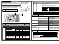
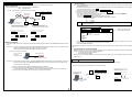
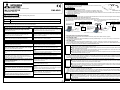
WT04918X01
2│Before Using the MN Converter
M-NET transmission line
Check the box contains the following parts:
(1) MN Converter (Including the M-NET transmission line with the Connection clips)
(2) Installation manual (This manual)
3│Functions
MITSUBISHI ELECTRIC Air-Conditioner Network system
MN CONVERTER
MN Converter
MN Converter has the following two functions.
(1) M-NET/RS-232C(USB)Converter: In order to confirm the operation status of the air conditioner using MAINTENANCE TOOL, the
signal from the M-NET transmission line is converted to the RS-232C (USB) signal.
(2) Remote error notification: It connects to the public network through the modem. Error of the air-conditioner will be reported to the
distant service center and etc.
CMS-MNG
Installation Manual
1│Safety precautions
4│Connections
●Before using the device, thoroughly read the following safety precautions.
The MN Converter has 2 operation modes. Connection methods differ with the each mode. Refer to the figure below for settings.
(1) Maintenance mode (Use with a MAINTENANCE TOOL)
(2) Remote error notification mode (Use as a remote error notification device)
The MAINTENANCE TOOL switches the operation mode. Please refer to the Operating manual of the MAINTENANCE TOOL.
[Maintenance mode]
[Remote error notification mode]
●Symbol explanations are shown below.
WARNING
This symbol indicates that failure to follow the instructions exactly as stated poses the risk of serious injury or death.
CAUTION
This symbol indicates that failure to follow the instructions exactly as stated poses the risk of serious injury or damage to the unit.
●After reading this manual, give it to the user to retain for future reference.
When the user changes, make sure that the new user receives this manual.
Personal computer with
the installed
MAINTENANCE TOOL
Outdoor
Unit
WARNING
Only use specified cables. Securely connect each cable so
that the terminals do not carry the weight of the cable.
Improperly connected or fixed cables or short-circuited cables may
produce heat and start a fire.
When malfunctions occurs, stop the device immediately.
Continuous use of the device after malfunction may result in electric
shock or fire. If the device malfunctions (if burning smells), stop
operation and disconnect the transmission line.
Indoor Unit
If the device is installed in an unstable place, where the unit may fall, in a
place where the device may get wet, or in a place where the wiring may
be easily disconnected, fire or electric shock may result.
Personal computer with
built-in modem (If there
is built-in modem, a
modem is required
separately.)
Shield RS-232C cable (cross
cable) or Shield USB cable
Do not make any modifications or alternations to the
device.
Only use the rated power supply.
Do not dispose of the device by yourself.
Improper rated power supply may result in fire or malfunction.
To dispose of the device, consult your dealer.
4.1.1 RS-232C cable
Do not install the device where there is a risk of leakage of flammable
gas. If gas leaks and accumulates around the device, fire or burst may
result.
Do not use the device in an unusual environment.
Do not install the device where a large amount of oil (including the
machine oil), steam, or sulphide gas is present. Doing so may lead to a
remarkable drop in performance, or malfunction.
Never supply AC power such as AC100V or AC200V and/or a
voltage greater than DC 30V.
Doing so may result in breakdown, ignition or fire. Supplied voltage of this
device is DC30V maximum.
Never pull or twist the transmission line.
Doing so may result in fire or malfunction.
If water, metal objects or extraneous matter enters the
device, stop the operation and disconnect the transmission
line.
Continuous use of the device may result in fire or electric shock.
Never wipe the device with benzene, thinner, chemical rags,
etc.
Modem
ME
Remote
controller
Shield RS-232C
cable (straight cable)
Use a shielded RS-232C 9Pin- 9Pin cross cable (commercially available length: 1.5 m, 59 in, 4.9 ft max) to connect the MN
Converter to the personal computer.
4.1.2 USB Cable
Use the shielded USB cable (commercially available length: 1.5 m, 59 in, 4.9 ft max) to connect to the personal computer.
When the USB cable is used, installation of drivers is required. Refer to the Operating manual of the MAINTENANCE TOOL. These
drivers are contained in the setup CD attached to the MAINTENANCE TOOL.
Notes
● The device can be connected to the personal computer using either the RS-232C cable or the USB cable. However, both
cables cannot connect to the personal computer at once.
● When using the remote error notification mode, the device cannot connect to the personal computer with the RS-232C
cable. Only USB cable can be used.
●Select the RS-232C cable depending on the serial interface of the personal computer to be used. If the form of the
connector shape is special, consult a personal computer dealer.
● Select the USB cable depending on the USB interface of the personal computer to be used. The USB connector to be
connected to the MN Converter is Type B.
Do not use the device for special environment.
This device is exclusively for maintenance. Do not use it for any purpose
other than maintenance. Doing so may cause malfunction.
Use standard wires with the proper current capacity.
Improper current capacity may result in electrical leakage or fire.
Doing so may cause deformation or malfunction.
Do not put dangerous goods around the device.
M-NET transmission line
The MN Converter is equipped with the D-SUB 9Pin connector (male) and the USB connector (Type B).
CAUTION
Do not use in any place at a temperature of more than 40°C
(104°F) or less than 0°C (32°F) or exposed to direct sunlight.
Indoor Unit
*M-NET address is set with the MAINTENANCE TOOL.
4.1 Connection to the personal computer
Doing so may result in electric shock or fire.
Indoor Unit
M-NET transmission line
Improper modifications or alternations may result in electric shock or fire.
Consult the dealer for alternations.
Do not place the device in highly dusty, humid or damp
locations.
Public network
Outdoor
Unit
ME
Remote
controller
Check the installation site and the connection status.
Indoor Unit
Always disconnect the transmission line by grasping the
plug.
Pulling the cord may damage the transmission line, preventing normal
measurement or causing equipment breakdown.
Do not splash water on the device or touch it with wet
hands.
4.2 Connection to the air-conditioner
To connect the MN Converter and the air conditioner, use the M-NET transmission line crocodile clip to the M-NET terminal block of
the outdoor unit or the remote controller. (No polarity.) To connect the MN Converter and the air conditioner (M-NET transmission line),
strictly follow the instructions mentioned below.
● Check the voltage of M-NET transmission line so that it does not exceed DC 30V before connection.
!
● Do not touch M-NET transmission line and transmission terminal with hands.
Caution ● To extend the M-NET transmission line, if connecting the MN Converter and outdoor unit, be sure to use reinforced
insulation transmission cable. Contact your dealer for further detail.
● Do not connect the M-NET transmission line to the power terminal block of the outdoor unit etc. Doing so may result in fire.
● If the MN Converter is consistently connected, use eyelet terminals instead of crocodile clips to connect the M-NET
terminal block. Connection must be performed by authorized personnel.
Doing so may result in electric shock or equipment breakdown.
Do not use the device if the cables or transmission line are
damaged.
△
There is a risk of equipment breakdown, or measurement errors from a
transmission line short circuit.
Do not place objects on top of the device.
There is a risk of malfunction or injury.
Do not spray any insecticide or flammable spray to the
device.
4.3 Connection to the modem
Do not place such as the flammable spray around this device, or spray it
directly to the device. Doing so may result in fire or burst.
Connect the modem (including GSM modem) to the MN Converter with the Shield RS-232C straight cable (commercially available
length: 1.5 m, 59 in, 4.9 ft max). You cannot use USB cable.
To set “Remote error notification” function, various settings (e.g. reception settings) must be made on a personal computer (with the
modem or built-in modem). Register the phone number and the building name to be contacted when an error occurs, and the error
type to be notified. Refer to the Operating manual of the MAINTENANCE TOOL.
Notes
● When “Remote error notification” function is set, the receiving side personal computer must not turn off.
● When the MAINTENANCE TOOL is operated through the modem, “Remote error notification” function does not work.
● When “Remote error notification” function is set, MN Converter is counted as one of the System remote controller units
that can be connected to the indoor unit. “Remote error notification” function cannot be used when more than five units
are connected.
Attention ● When “Remote error notification” function is set, be sure to register the correct phone number to be contacted.
Do not touch any PCB (Printed Circuit Board) with your
hands or with tools. Do not allow dust to collect on the PCB.
Doing so may cause fire or an electric shock.
Doing so may result in discoloration or malfunction. To remove heavy
stains, soak a cloth in neutral detergent mixed with water, wring it out
thoroughly, wipe the stains off, and wipe again with a dry cloth.
1
2
5│Checking the Operation
LED7 (Green)
(Power
indicator)
After connecting the M-NET transmission line, look through the LED display
hole on the casing side to check the LED7 light (Green: power) turns on.
If the LED7 light (Green) is not turned on, no power is being supplied to the
MN Converter. Check the connection of the transmission line and/or the wiring.
(The power is supplied from the M-NET transmission line.)
RS-232C
USB
STATUS/POWER
RS-232C Connector USB Connector to
personal computer
to personal
computer/modem
LED5 (Yellow)
LED
number
LED5
(Yellow)
Functions
Operation status LED
(Status indicator)
6.1 Configuration
Upper casing
△
Caution
Transmission
line
Control board
To avoid the risk of electric shock or damage to the
board, never disassemble the MN Converter with the
transmission line connected. Be certain to disconnect
the transmission line before starting the operation.
!
【For the both maintenance mode and the remote error notification mode】
Lit: Ready for operation. (normal)
Unlit: Not ready for operation. (error)
【For the remote error notification only.】
Blink: When the remote error notification activates, the LED light blinks
according to the following blink patterns:
···Lit (Unit: second)
Pattern Explanation Priority*
Blinking pattern
Operation status
High 0.5
1
Slow blink
Modem error
2.0
0.5
↑
Remote error notification
2.0
0.5
2.0
2
Long blink
↑
failed
↑
3
Double blink
Redialing
0.2-0.1-0.2-0.5
Low
4
Blinking
Air-conditioner error
0.5 0.5
6│MN Converter Configuration and Self-Diagnose Function
The MN Connector consists of the upper casing, control board, power
supply circuit board, the lower casing and the transmission line.
For the maintenance and self-diagnose etc., remove the casing screws
(4 screws) to remove the upper casing.
Function details
Power supply
circuit board
Lower casing
Casing screw (4 screws)
(*When all of the operation statuses occur at a time, the status with the highest priority is displayed.)
Refer to the Operating Manual of the MAINTENANCE TOOL for more information.
6.2 Names and functions of parts (control board)
LED1
LED2
LED3
LED4
Power supply circuit board connecting connector
LED6
(Green)
LED7
(Green)
→ON
USB transmission/
reception status LED
Power LED
LED6 blinks on transmitting and receiving data through USB communication.
LED7 lights when the MN Converter power turns on.
1
7│Troubleshooting
SW1
8
Check the operation according to the following contents.
Phenomenon
Check items
MN Converter does not run Check whether the power LED (LED7) is lit.
(*Factory setting: All are set to OFF.)
Check whether the operation status LED
(LED5) is lit.
USB connector
RS-232C D-SUB 9-Pin connector
SW1
1 to 5
6 to 8
Function name
Not used
For maintenance
LED6
LED5
LED1 to 4
(Green)
Check whether the cable is firmly connected.
Check the COM Port number of the cable
connected to the personal computer.
Check the cable type.
USB Communication error
Check whether the cable is firmly connected.
The drivers are not installed.
Operation status LED
(LED5: yellow) is blinking
with pattern 1(Slow blink).
Operation status LED
(LED5: yellow) is blinking
with pattern 2(Long blink).
Communication failure with the modem that is
connected to the MN Converter.
LED7
Function details
Set all switches to OFF.
Change the settings to check the status.
Settings to be made are shown below.
Remarks
Factory setting: All are
set to OFF.
6.3 Self-Diagnose function
LED
number
RS-232C Communication
error
Functions
Function details
LED for maintenance
Displayed contents are changed according to SW1-6 to 8 settings.
SW1
Meaning
Functions
-6
-7
-8
LED1
LED2
LED3
OFF
OFF
OFF
Operation status Maintenance
display
mode
OFF
OFF
ON
OFF
ON
OFF
OFF
ON
ON
ON
OFF
OFF
ON
OFF
ON
ON
ON
OFF
ON
ON
ON
Communication
status display
Error status
display
Communication
error detail 1
Communication
error detail 2
Remote error
notification error
detail 1
Remote error
notification error
detail 2
Not used
M-NET
transmission
Air-conditioner
malfunction
Duplicated
address error
No polar settings
error
Unregistered
phone number to
be connected.
Call redialing
Remote error
notification
mode
M-NET
reception
Preliminary
error
Bus busy error
LED4
Constant
monitor status
Remote error
notification status
RS-232C
transmission
Communication
error
H/W error
RS-232C
reception
Remote error
notification error
Remote error notification failed.
Remedy
When the power LED (LED7) is not lighting, no power is
being supplied. Check the wiring.
Check whether the voltage of the M-NET transmission
contact is between DC17-30V.
When the operation state LED (LED5) does not light,
this device does not work properly. Check whether
SW1-1 to 5 are turned OFF.
Connect the cable firmly.
Change the COM port number to be used on the
MAINTENANCE TOOL screen.
When RS-232C is connected to the personal computer,
use the cross cable. When it is connected to the modem,
use the straight cable.
Firmly connect the cable.
Install the drivers. (The drivers are contained in the
setup CD attached to the MAINTENANCE TOOL
Ver.4.20 or later.
Check that the power of the modem is turned on and
that the communication cable of the modem is correctly
connected.
Check the “Report log display” screen of the
MAINTENANCE TOOL. Then check the modem that is
connected to the MN Converter, phone line, and the
remote error notification status. (Refer to the Operating
Manual of the MAINTENANCE TOOL for more
information.)
8│Specification
Item
Specification
Dimensions
160 (W) × 37 (H) × 137 (D) mm / 6 1/4 (W) × 1 1/2 (H) × 5 3/8 (D) in
Weight
0.65 kg / 11/2 lb
Power Supply (*1)
30 VDC / 24 VDC (M-NET)
Rated Power Consumption
2W
Operating temperature range 0 to 40°C [32 to 104°F]
Temperature
Environment Conditions
Storage temperature range
-20 to 60°C [-4 to 140°F]
Humidity
30 to 90%RH (no condensation)
RS-232C (D-SUB 9Pin: male connector)
Interface
USB connector (Type B)
*1: Supply electric power from a power supply unit for the transmission line or an outdoor unit.
Transmitted
No ACK error
No response
data error
error
No connection No response
Call timeout
information
from the modem
* Do not set the functions.
3
4
Appendix│How to connect to the modem
[Setting Procedures]
1) After connecting the MAINTENANCE TOOL that is already installed on the personal computer and the modem, start the
MAINTENANCE TOOL.
2) On the Select Monitor mode screen, choose MN CONVERTER, Remote Connection, CMS-MNG-E, and the COM port that
are being connected and then choose Select .
3) Jump to the Connection setting screen. Choose MODEM initial setting .
4) Jump to the Connection modem initial setting screen. Choose New settings .
5) Jump to the AT Command transmit screen.
Enter the AT command corresponding to the procedure (2) (a), (b), (c) in the space under AT COMMAND.
Then choose Transmission beside the entry space.
*Refer to the manual of the modem and enter the proper AT command.
In case of U.S. robotics 56K FAXMODEM, see below for the proper AT command.
(a). → AT&D0
(b). → AT&R1
(c). → AT&W0
Notes ●AT command may differ depending on the modem type. Check the proper AT command referring to the
manual of the modem.
This section describes how to connect the MN Converter to the modem and use it through the public line.
1. Basic configuration
Recommended modem: Analog - U.S.Robotics 56K FAXMODEM
GSM - SIEMENS MC35
[System configuration figure connected with the modem (Example)]
Indoor unit
Public network
Outdoor
unit
Shield RS-232C
(Straight cable)
Indoor unit
M NET transmission line
ME
Remote
controller
Modem (GSM modem)
MN Converter
Personal computer
built-in modem
Example) GSM modem SIEMENS MC35
Shield RS-232C Straight Cable
D-SUB 9Pin (male) - D-SUB 9Pin (female)
[Connection diagram of the connection cable]
1
2
3
4
5
6
7
8
9
Pin No.
1
2
3
5
6
7
8
Pin No.
1
2
3
4
5
6
7
8
9
Pin No.
8
3
2 20 7
6
4
5 22
Modem side
DB25 (male)
4
→AT&D0
←OK
→AT&R1
←OK
→AT&W0
←OK
9
Modem side
2. Modem initialization
The modem of MN Converter side is required to be initialized. Modem setting procedures by the MAINTENANCE TOOL are shown
below.
Procedure (1) Connect the personal computer with installed MAINTENANCE TOOL and the modem which is on the MN Converter
side using the Shield RS-232C cable (straight cable(*1)) as shown below.
*1:Refer to the previous chapter for the details of the cable connection.
Transmission
② Chose “Transmission” after
entering the AT command.
③ The setting command is transmitted.
④ The result
6) When “Transmission” is chosen, AT command is sent to the modem. When the setting is completed, the modem sends back
OK command. This is the end of the modem setting by AT command.
7) Close the MAINTENANCE TOOL.
After initializing the modem, connect each unit as shown in the System configuration figure connected with the modem (Example) on
page 5.
3. Communication error with the modem
When the MN Converter cannot communicate with the modem properly, disable data compression function and set the baud rate to
9600bps. For settings, refer to chapter 2. Modem initialization.
(1). Data compression function: Disabled
(2). Baud rate setting: 9600bps
Send the AT command corresponded to the contents (1) and (2) to the modem, and make the settings. Refer to the manual of the
modem and set.
[Connection to the modem at Initialization]
Personal computer with
the installed
MAINTENANCE TOOL
① Enter the AT command.
AT COMMAND
AT&W0
MN Converter side
DB9 (female)
Pin No.
DB9 (male)
Example: AT command transmit screen
[Connection diagram of the connection cable]
MN Converter side
DB9 (female)
Example) U.S.Robotics 56K FAXMODEM
Shield RS-232C Straight Cable
D-SUB 25Pin (male) - D-SUB 9Pin (female)
Modem (GSM modem)
Shield RS-232C straight cable (*1)
Appendix│How to connect RS-232C to a Personal Computer
Procedure (2) After finishing the cable connection, activate the MAINTENANCE TOOL and jump to the modem setting screen. Set 3
items shown below. Refer to the [Setting procedures] on page 6. As the AT commands are used for settings, also
refer to the manual of the modem.
This section describes how to connect the MN Converter through RS-232C to the Personal Computer.
[System configuration figure connected with the Personal computer (Example)]
(a) Set the modem to ignore the Data Terminal Ready (DTR) by AT command.
(b) Set the modem to ignore the Required Transmission Service (RTS) by AT command.
(In case of the modem with no RTS settings, set the modem to deactivate the H/W flow control by AT command.)
(c) Set the modem not to volatilize the memory of step (a) and (b) by AT command.
Personal computer with
the installed
MAINTENANCE TOOL
Outdoor
Unit
Indoor Unit
Indoor Unit
M-NET transmission line
ME
Remote
controller
[Connection diagram of the connection cable]
Shield RS-232C cross cable
D-SUB 9Pin (female) – D-SUB 9Pin (female)
MN Converter side
DB9 (female)
Pin No.
1
2
Pin No.
1
2
DB9 (female)
3
4
5
6
7
8
9
3
4
5
6
7
8
9
Personal computer side
Shield RS-232C cable
(cross cable)
5
6
This product is designed and intended for use in the residential,
commercial and light -industrial environment.
This product at hand is
based on the following
EU regulations:
・ Low Voltage Directive 73/23/EEC
・ Electromagnetic Compatibility Directive
2004/108/EC
NOTE:
This equipment has been tested and found to comply with the limits for a Class B digital device, pursuant to
Part 15 of the FCC Rules. These limits are designed to provide reasonable protection against harmful
interference in a residential installation. This equipment generates, uses and can radiate radio frequency
energy and, if not installed and used in accordance with the instructions, may cause harmful interference to
radio communications.
However, there is no guarantee that interference will not occur in a particular installation.
If this equipment does cause harmful interference to radio or television reception, which can be determined
by turning the equipment off and on, the use is encouraged to try to correct the interference by one or more
of the following measures:
-
Reorient or relocate the receiving antenna.
Increase the separation between the equipment and receiver.
Connect the equipment into an outlet on an circuit different from that to which the receiver is
connected.
Consult the dealer or an experienced radio/TV technician for help.
HEAD OFFICE: TOKYO BLDG., 2-7-3, MARUNOUCHI, CHIYODA-KU, TOKYO 100-8310, JAPAN
WT04918X01
7
8