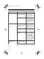
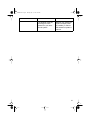
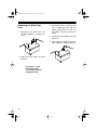
1
12-2015.fm Page 1 Tuesday, July 13, 1999 3:47 PM
Cat. No. 12-2015
OWNER’S MANUAL
Please read before using this equipment.
XL-150
High Power 4-Channel
Stereo Amplifier
12-2015.fm Page 2 Tuesday, July 13, 1999 3:47 PM
FEATURES
Your Optimus XL-150 High Power 4Channel Stereo Amplifier is designed
to give added punch and power to your
vehicle’s existing autosound system.
The amplifier produces up to 40 watts
(front) and 110 watts (rear) per channel of clean, powerful sound at all audio frequencies with minimum distortion. You can connect your autosound system’s low-level or speakerlevel outputs to this amplifier.
Its features include:
14K Gold-Plated Noise-Isolated
Low-Level Input Jacks — let you connect low-level (preamplifier) signal inputs to match your autosound system’s output for the best high-fidelity
performance.
Mute Turn On Circuit — eliminates
the thump you hear when you turn on
some amplifiers.
Power Indicator — lights when power
is supplied to the amplifier.
Auto-Off — protects the amplifier by
temporarily shutting down if it gets too
hot or it detects an input overload. The
amplifier restarts automatically when it
cools or the problem is corrected.
Protection Indicator — lights if the
amplifier shuts down its rear channel.
Short Circuit Protection — distorts
the amplifier’s sound if any output
channel shorts, alerting you to turn off
the autosound system.
14K Gold-Plated Speaker Terminals
— designed for low impedance, high
conductivity, and minimum corrosion,
to provide the highest signal transfer
and lowest sound distortion.
Input Level Controls — let you adjust
the level of the audio signals that enter
the amplifier.
Automatic Power Switching — can
automatically turn the amplifier on or
off when you turn your autosound system on or off (depending on how you
hook up the amplifier).
© 1997 Tandy Corporation.
All Rights Reserved.
Optimus and RadioShack are registered trademarks used by Tandy Corporation.
2
12-2015.fm Page 3 Tuesday, July 13, 1999 3:47 PM
CONTENTS
Preparation ........................................................................................................... 4
Supplied Hardware ......................................................................................... 4
Before You Begin the Installation .................................................................... 4
Choosing a Mounting Location ................................................................. 5
Preparing the Mounting Area .................................................................... 5
Routing Cables and Wires ........................................................................ 5
Installation Order ............................................................................................. 5
Before You Make the Connections .................................................................. 6
Connecting Ground and Switched/Primary Power ........................................... 7
Connecting Inputs ............................................................................................... 9
Low-Level Inputs ............................................................................................. 9
High-Level (Speaker Wire) Inputs ................................................................. 11
Four Speaker Outputs ............................................................................ 12
Two Speaker Outputs ............................................................................. 13
Connecting Speakers .................................................................................... 14
Preparing the Speaker Wires ................................................................. 14
Connecting the Speakers to the Amplifier ............................................... 15
Completing the Installation .............................................................................. 16
Testing the Connections ................................................................................ 16
Mounting the Amplifier .................................................................................. 16
Operation ............................................................................................................ 18
Turning On the Amplifier ............................................................................... 18
Adjusting the Audio Level ............................................................................. 18
Troubleshooting ................................................................................................ 19
Care and Maintenance ......................................................................................
The FCC Wants You to Know .......................................................................
Replacing a Fuse ..........................................................................................
Replacing the SFE-Type Fuse ................................................................
Replacing the Blade-Type Fuse .............................................................
21
21
22
22
23
Specifications .................................................................................................... 24
3
12-2015.fm Page 4 Tuesday, July 13, 1999 3:47 PM
PREPARATION
SUPPLIED HARDWARE
Your amplifier comes with the following items. Be sure you locate everything shown
before you store or dispose of the packing materials.
(illustration - show all amplifier parts, wires, and hardware)
BEFORE YOU BEGIN THE INSTALLATION
Before you install your amplifier, read all the instructions in this owner’s manual.
And, you should be able to answer all of these questions about your vehicle’s electrical and autosound systems.
• Does my vehicle have an autosound system, such as a car stereo or CD
player, already installed? (You must have an existing autosound system to use
this amplifier.)
• How do I connect a wire to the fuse box?
• Which of the autosound system’s wires is the power wire?
• Which of the autosound system’s terminals are low-level outputs and which are
high-level (speaker) outputs?
Also, be aware that installation in your vehicle might require cutting or modifying
your vehicle.
4
12-2015.fm Page 5 Tuesday, July 13, 1999 3:47 PM
Choosing a Mounting
Location
A good location for mounting the amplifier is in your vehicle’s trunk. Wherever you decide to mount it, choose a
location that:
• Does not interfere with the vehicle’s operation
• Lets you drill mounting holes without damaging other vehicle components
• Allows enough space around the
cooling fins for proper airflow and
cooling
• Lets you easily see the amplifier’s
POWER and PROTECTION indicators
Warning: The amplifier gets very hot
while it is on. Do not touch the amplifier
or place flammable objects near it
while it is on.
Preparing the Mounting Area
Before you mount the amplifier, make
sure you have all the materials you
need, such as an adapter harness,
additional wire, shielded audio cables,
and 16- or 18-gauge marked or colorcoded wires.
Then confirm that the amplifier fits in
your vehicle’s available mounting area. This amplifier requires a 2 1/16-inch
high by 10-inch wide by 121/8-inch deep
(5.2 ¥ 25.4 ¥ 30.8 cm) mounting area
with adequate ventilation space.
Routing Cables and Wires
Avoid routing the connection cables
and any speaker wires near moving
parts or sharp edges. You can usually
route wires and cables along the wiring
channel beneath the vehicle’s door facings by carefully removing the molding
that holds the carpet in place. After
routing the cables and wires, replace
the molding.
INSTALLATION ORDER
For trouble-free installation, simply follow the sections in this Owner’s Manual in order. First, temporarily connect
the amplifier to:
1
Ground and power
2
Your autosound system’s outputs
3
Your speakers
Then test the connections. When you
verify that everything works as expected, disconnect the amplifier, mount it in
your vehicle, and reconnect it.
Caution: If you do not make the connections in the order shown, damage
to the amplifier and your autosound
system is possible if any wire connections are made incorrectly.
Note: For easier installation, mark
each wire you plan to connect with the
name of the terminal you will connect
it to.
5
12-2015.fm Page 6 Tuesday, July 13, 1999 3:47 PM
BEFORE YOU MAKE THE
CONNECTIONS
The supplied connection cables include all the lead wires you need to
connect the amplifier to ground, power,
and your existing autosound system.
Cautions:
• For added safety and to protect
your amplifier and autosound system, disconnect the cable from
your vehicle’s negative (–) battery
terminal before you begin.
Important:
• Do not cut these wires. If you cut
any wire, you cannot obtain a
refund or exchange on this product. However, RadioShack will
provide warranty service if you cut
a wire and find the product is
defective.
• If the connectors on your vehicle’s
autosound system are not compatible with the amplifier’s connectors, you might need an
adapter harness to complete the
connections. RadioShack stores
sell adapter harnesses for most
vehicles.
You might need additional wire, depending on your individual autosound
system, to complete the connections.
Your local RadioShack store carries a
full line of wire and wire management
accessories.
6
• Be sure your front speakers can
handle as much as 20 watts per
channel and your rear speakers
as much as 55 watts per channel
of power. Each speaker must
have an impedance of at least 4
ohms. Your local RadioShack
store carries a full line of speakers.
To make it easier to gauge wire length
and connect the amplifier, temporarily
place the amplifier as close as possible
to the selected mounting location.
12-2015.fm Page 7 Tuesday, July 13, 1999 3:47 PM
CONNECTING GROUND AND
SWITCHED/PRIMARY POWER
Follow these steps to connect the amplifier to ground, switched power, and
primary power.
1. If you have not done so already,
disconnect the cable from your
vehicle’s negative (–) battery terminal.
2. Use a screwdriver to connect the
spade end of the supplied black
ground wire to the amplifier’s GND
(ground) terminal.
3. Connect the black ground wire’s
other end to a chassis ground,
such as a metal bolt attached to a
metal part of the vehicle’s frame.
Be sure the bolt is not insulated
from the chassis by a plastic part.
4. Use a screwdriver to connect the
spade end of the supplied blue/
white wire to the amplifier’s REM
(remote power) terminal.
7
12-2015.fm Page 8 Tuesday, July 13, 1999 3:47 PM
5. Connect the blue/white wire’s
other end to your autosound system’s switched power lead using
one of the supplied twist-on terminal connectors.
(illus)
This connection turns on the
amplifier when you turn on the
autosound system, and turns off
the amplifier when you turn off the
autosound system. This prevents
your vehicle’s battery from being
drained if you leave your amplifier
on when you turn off your autosound system.
If your autosound system does
not have a switched power lead,
connect the blue/white wire’s
other end to a point in your vehicle’s fuse block that has power
only when you turn on the ignition
or turn the key to ACC.
This connection turns on the
amplifier when you turn on the
ignition or turn the key to ACC,
and turns off the amplifier when
you turn off the ignition. This prevents your vehicle’s battery from
being drained if you leave your
amplifier on when you turn off the
ignition.
8
6. Use a screwdriver to connect the
spade end of the supplied red
power cable (with in-line fuse
holder) to the amplifier’s + 12V terminal.
7. Connect the other end of the red
power cable to your vehicle’s positive (+) battery terminal as shown.
Then tighten the terminal.
(illus)
Caution: Due to the amplifier’s
high current requirement, you
must connect the red power
cable’s fused end directly to the
vehicle’s positive (+) battery terminal or damage to your vehicle’s
wiring could result.
Do not reconnect your vehicle’s negative (–) battery cable yet.
12-2015.fm Page 9 Tuesday, July 13, 1999 3:47 PM
CONNECTING INPUTS
LOW-LEVEL INPUTS
You can connect your autosound system’s low-level line out jacks to the amplifier’s low-level line in jacks.
If your autosound system does not have low-level line out jacks, see “High Level
(Speaker Wire) Inputs” on Page 11 to connect your amplifier.
1. Temporarily place the amplifier as close as possible to the selected mounting
location.
2. If your autosound system has four separate line out jacks , connect the autosound system to the amplifier as shown:
(illus)
Note: For the best results, use shielded audio cables such as Cat. No. 42-2368
(not supplied).
9
12-2015.fm Page 10 Tuesday, July 13, 1999 3:47 PM
If your autosound system has two line out jacks (left and right), connect the
autosound system to the amplifier as shown:
(illus)
Note: For the best results, use shielded audio Y-adapters such as Cat. No. 422435 (not supplied).
10
12-2015.fm Page 11 Tuesday, July 13, 1999 3:47 PM
HIGH-LEVEL (SPEAKER
WIRE) INPUTS
If your autosound system does not
have low-level line out jacks but has
only speaker outputs, connect your
autosound system’s speaker outputs
to the amplifier’s HIGH INPUT jacks.
• If your autosound system has four
speaker outputs, see “Four
Speaker Outputs” on Page 12 to
connect your system’s speaker
outputs to the amplifier using
either a floating or common
ground connection.
Note: A floating ground connection
lets the amplifier provide more power
to each speaker, but requires that you
connect a separate wire to each
speaker terminal. A common ground
connection lets you use fewer wires to
connect the speakers to the amplifier,
but reduces the amount of power supplied to the speakers from the amplifier.
Use the supplied wire harnesses and
the supplied twist-on terminal connectors to make the appropriate connections.
• If your autosound system has two
speaker outputs, see “Two
Speaker Outputs” on Page 13 to
connect your system’s speaker
outputs to the amplifier using either a floating or common ground
connection.
11
12-2015.fm Page 12 Tuesday, July 13, 1999 3:47 PM
Four Speaker Outputs
Floating Ground Connection
(illustration)
Common Ground Connection
(illustration)
12
12-2015.fm Page 13 Tuesday, July 13, 1999 3:47 PM
Two Speaker Outputs
Floating Ground Connection
(illustration)
Common Ground Connection
(illustration)
13
12-2015.fm Page 14 Tuesday, July 13, 1999 3:47 PM
CONNECTING
SPEAKERS
You can connect two or four speakers
to the amplifier and your autosound
system.
Preparing the Speaker Wires
Caution: You must connect a separate wire to each speaker terminal as
described in the following procedures.
Only use a common ground wire or
chassis ground if your autosound system is wired for it.
Notes:
• We recommend you use 16- or 18gauge marked or color-coded
wires to help you correctly connect
the speakers to your amplifier.
• Color-coded wires have a stripe
running down one of the conductors or different colored insulation
for each conductor. Your local
RadioShack store has a wide
selection of speaker wire to
choose from.
• For the maximum bass response
and the best overall performance,
keep your speakers properly
phased (connect + to + and – to –).
14
1. With the speakers placed in their
approximate locations, run one
wire from each speaker to the
amplifier.
If you are connecting a subwoofer,
run two wires from each of the
subwoofer’s terminals to the
amplifier.
2. Separate each wire’s two conductors at both ends for a length of
about 4 inches.
3. Strip the insulation from the ends
of each conductor to expose 1/4
inch of wire. Twist the ends to
secure loose strands.
Wire Strands
Conductors
12-2015.fm Page 15 Tuesday, July 13, 1999 3:47 PM
Connecting the Speakers to the Amplifier
(illustration)
1. Use a screwdriver to connect the front left speaker’s positive (+) wire to the
amplifier’s SPEAKERS FL (+) terminal.
2. Use a screwdriver to connect the front left speaker’s negative (–) wire to the
amplifier’s SPEAKERS FL (–) terminal.
3. Repeat Steps 1–2 to connect the front right speaker’s positive (+) and negative
(–) wires to the amplifier’s SPEAKERS FR (+) and SPEAKERS FR (–) terminals.
4. Repeat Steps 1–3 to connect the rear left and rear right speaker’s positive (+)
and negative (–) wires to the amplifier’s SPEAKERS RL (+), SPEAKERS RL (–),
SPEAKERS RR (+), and SPEAKERS RR (–) terminals.
15
12-2015.fm Page 16 Tuesday, July 13, 1999 3:47 PM
COMPLETING THE INSTALLATION
TESTING THE
CONNECTIONS
MOUNTING THE
AMPLIFIER
Before you continue, make sure you
have securely made all connections.
Then reconnect the cable to the vehicle’s negative (–) battery terminal.
Once you verify that the amplifier is
connected properly, follow these steps
to mount it.
Set LEVEL (MIN/MAX) on both ends of
the amplifier to its mid position (see
“Adjusting the Audio Level” on
Page 18). Then turn on your vehicle’s
ignition and autosound system to confirm that the amplifier and autosound
system operate properly. The amplifier turns on after a few seconds.
If you cannot quickly confirm whether
the autosound system and amplifier
are working properly, turn off your
vehicle’s ignition and disconnect
the cable from your vehicle’s negative (–) battery terminal. Then recheck your connections.
After you test the autosound system
and amplifier and verify that everything is properly connected and working, follow the instructions in
“Mounting the Amplifier.”
16
1. Disconnect the cable from the
vehicle’s negative (–) battery terminal.
2. To make mounting more convenient, temporarily disconnect the
amplifier’s connections (ground,
primary power, remote power,
your autosound system’s input,
and speakers).
Note: If you have not already
done so, be sure to mark each
wire with the name of the terminal
you will reconnect it to.
3. Using the mounting holes on the
amplifier as a guide, mark the
positions for the mounting holes.
12-2015.fm Page 17 Tuesday, July 13, 1999 3:47 PM
4. Drill 9/64-inch (3.57 mm) holes at
the marked locations, being careful not to damage anything behind
the mounting surface.
7. Reconnect the cable to the vehicle battery’s negative (–) terminal.
5. Secure the amplifier to the mounting surface using the supplied
sheet metal screws and washers.
6. Reconnect the wiring.
8. Reset your vehicle’s clock, your
autosound system’s tuner memory, and other timer/memory
devices.
17
12-2015.fm Page 18 Tuesday, July 13, 1999 3:47 PM
OPERATION
TURNING ON THE
AMPLIFIER
The amplifier automatically turns on a
few seconds after you turn your vehicle’s ignition switch to ACC or ON, or
turn on your autosound system, depending on how you wired the system.
The POWER indicator on the side of the
amplifier lights when the amplifier is on.
(illustration)
1. Use a screwdriver to turn both
LEVEL (MIN/MAX) controls fully
counterclockwise to MIN.
(illustration)
2. Turn the autosound system’s volume control to about one-third of
its full range.
3. Adjust both LEVEL (MIN/MAX) controls to a comfortable listening
level.
Important: Your amplifier requires 25
amps or more of power from your vehicle’s battery during operation. To protect your battery from discharging, do
not operate the amplifier unless your
vehicle is running.
Note: Your amplifier temporarily shuts
down if it gets too hot, then restarts automatically once it cools.
4. Turn up the autosound system’s
volume control until the sound
begins to distort. Then immediately turn the volume down to a
point just before where the distortion began.
Caution: Never turn up the autosound system’s volume control
more than needed to adjust the
audio level, or more than twothirds of its maximum volume.
ADJUSTING THE AUDIO
LEVEL
5. Adjust both LEVEL (MIN/MAX) controls until the sound is at the maximum level you want the amplifier
to produce.
For the best performance, you must
set LEVEL (MIN/MAX) on the end of the
amplifier to adjust the level of the audio
signals that enter the amplifier.
6. Adjust the autosound system’s
volume control to a comfortable
listening level.
18
12-2015.fm Page 19 Tuesday, July 13, 1999 3:47 PM
TROUBLESHOOTING
We do not expect you to have any problems with your Optimus XL-150 High Power
4-Channel Car Amplifier, but if you have a problem, this chart might help. If not,
take the amplifier to your local RadioShack store for assistance.
SYMPTOM
No power — the amplifier’s POWER indicator
does not light after the
vehicle’s autosound system is turned on
No sound
POSSIBLE CAUSE
SUGGESTION
Power problem.
Check the amplifier’s
and autosound system’s fuses and replace
them if necessary (see
“Replacing a Fuse” on
Page 23).
Vehicle’s ignition not
turned on.
Start the vehicle.
Amplifier not connected
to autosound system/
vehicle correctly.
Check all connections.
Autosound system not
turned on or volume set
to minimum.
Turn the autosound system on or adjust its volume.
Amplifier’s LEVEL (MIN/
MAX) controls set to min-
Adjust LEVEL (MIN/MAX).
imum.
Amplifier not connected
to autosound system/
vehicle correctly.
Check all connections.
The amplifier might have
shut down.
Turn your autosound
system off and let the
amplifier cool. Make
sure the amplifier is
properly ventilated. Then
turn your autosound system back on. The amplifier turns itself back on
when it has cooled.
19
12-2015.fm Page 20 Tuesday, July 13, 1999 3:47 PM
SYMPTOM
No sound (continued)
Distorted sound
The amplifier’s PROTECTION indicator
lights
20
POSSIBLE CAUSE
SUGGESTION
The amplifier might have
shut down (continued)
The amplifier detected
an input overload.
Reduce the autosound
system’s volume.
Power problem.
Check the amplifier’s
and autosound system’s fuses and replace
them if necessary (see
“Replacing a Fuse” on
Page 23).
The amplifier might be
receiving too much input
power from your autosound system.
Reduce your autosound
system’s output power
(if possible), or reduce
the autosound system’s
volume.
An output channel might
have shorted.
Take the amplifier to
your local RadioShack
store.
The amplifier might have
shut down.
Turn your autosound
system off and let the
amplifier cool. Make
sure the amplifier is
properly ventilated. Then
turn your autosound system back on. The amplifier turns itself back on
when it has cooled.
Amplifier not connected
to autosound system
correctly.
Check all connections.
12-2015.fm Page 21 Tuesday, July 13, 1999 3:47 PM
SYMPTOM
POSSIBLE CAUSE
The amplifier might be
receiving too much
power from your autosound system.
SUGGESTION
Reduce your autosound
system’s output power
(if possible), or reduce
the autosound system’s
volume.
21
12-2015.fm Page 22 Tuesday, July 13, 1999 3:47 PM
CARE AND MAINTENANCE
Your Optimus XL-150 High Power 4-Channel Stereo Amplifier is an example of superior design and craftsmanship. The following suggestions will help you care for
your amplifier so you can enjoy it for years.
Keep the amplifier dry. If it gets wet, wipe it dry immediately. Liquids
might contain minerals that can corrode the electronic circuits.
Keep the amplifier away from dust and dirt, which can cause premature wear of parts.
Handle the amplifier gently and carefully. Dropping it can damage circuit boards and cases and can cause the amplifier to work improperly.
Wipe the amplifier with a damp cloth occasionally to keep it looking
new. Do not use harsh chemicals, cleaning solvents, or strong detergents to clean the amplifier.
Modifying or tampering with the amplifier’s internal components can cause a malfunction and might invalidate your amplifier’s warranty and void your FCC authorization to operate it. If your amplifier is not performing as it should, take it to your local
RadioShack store for assistance.
THE FCC WANTS YOU TO KNOW
Your amplifier might cause TV or radio interference even when it is operating properly. To determine whether your amplifier is causing the interference, turn off your
amplifier. If the interference goes away, your amplifier is causing it. Try to eliminate
the interference by:
• Moving your amplifier away from the receiver
• Contacting your local RadioShack store for help
22
12-2015.fm Page 23 Tuesday, July 13, 1999 3:47 PM
REPLACING A FUSE
If the amplifier does not operate, you
might need to replace the red power
cable’s 25-amp SFE-type fuse or the
25-amp blade-type fuse on the amplifier’s back panel. Check both fuses.
Important: Let the amplifier cool
down and see if it starts again before
you assume a fuse needs to be replaced.
Caution: Do not use a fuse with ratings other than those specified here.
Doing so might damage your amplifier.
Replacing the SFE-Type Fuse
1. Disconnect the cable from the
vehicle’s negative (–) battery terminal.
2. Push together and twist the fuse
holder’s parts on the red power
cable until they spring apart. Then
remove the fuse.
(illus - show fuse holder)
3. If the fuse is blown, replace it. Use
only an SFE-type fuse with the
proper rating (available at many
automotive supply stores). The
fuse must be 25 amps.
4. Reassemble the fuse holder by
inserting the fuse into the longer
of the fuse holder’s ends, and
pushing together and twisting the
two parts until they latch.
5. Reconnect the cable to the vehicle’s negative (–) battery terminal.
23
12-2015.fm Page 24 Tuesday, July 13, 1999 3:47 PM
Replacing the Blade-Type
Fuse
1. Disconnect the cable from the
vehicle’s negative (–) battery terminal.
3. If the fuse is blown, replace it. Use
only a blade-type fuse with the
proper rating (such as Cat. No.
270-1084). The fuse must be 25
amps.
4. Grasp the fuse’s plastic end and
push it in.
5. Reconnect the cable to the vehicle’s negative (–) battery terminal.
2. Grasp the fuse’s plastic end and
pull it out.
(illustration - show
surrounding area,
fuse holder, and fuse
being pulled out)
24
12-2015.fm Page 25 Tuesday, July 13, 1999 3:47 PM
SPECIFICATIONS
Output Power:
Front ..................................... 10 Watts ¥ 2 @ 4 Ohms, 20–20 kHz, 0.5% THD
20 Watts ¥ 2 @ 4 Ohms, 20–20 kHz, 10% THD
15 Watts ¥ 2 @ 2 Ohms, 20–20 kHz, 1% THD
Rear ...................................... 45 Watts ¥ 2 @ 4 Ohms, 20–20 kHz, 0.5% THD
55 Watts ¥ 2 @ 4 Ohms, 20–20 kHz, 10% THD
45 Watts ¥ 2 @ 2 Ohms, 20–20 kHz, 1% THD
Frequency Response ........................................................... 20–20,000 Hz (±3 dB)
Power Supply Voltage .................................................. 14.4 VDC Negative Ground
Maximum Current Draw ................................................................................... 25 A
Dimensions (HWD) .............................................................. 21/16 ¥ 9 ¥ 121/8 Inches
(5.2 ¥ 23 ¥ 30.8 cm)
Net Weight .................................................................................................... 4.6 lbs
(2.1 kg)
Specifications are typical; individual units might vary. Specifications are subject to
change and improvement without notice.
25
12-2015.fm Page 26 Tuesday, July 13, 1999 3:47 PM
NOTES
26
12-2015.fm Page 27 Tuesday, July 13, 1999 3:47 PM
27
12-2015.fm Page 28 Tuesday, July 13, 1999 3:47 PM
Limited One-Year Warranty
This product is warranted by RadioShack against manufacturing defects in material and workmanship under normal use for one (1) year from the date of purchase from RadioShack company-owned stores and authorized RadioShack franchisees and dealers. EXCEPT AS PROVIDED HEREIN, RadioShack MAKES NO EXPRESS
WARRANTIES AND ANY IMPLIED WARRANTIES, INCLUDING THOSE OF MERCHANTABILITY AND FITNESS FOR A PARTICULAR PURPOSE, ARE LIMITED IN DURATION TO THE DURATION OF THE WRITTEN
LIMITED WARRANTIES CONTAINED HEREIN. EXCEPT AS PROVIDED HEREIN, RadioShack SHALL HAVE
NO LIABILITY OR RESPONSIBILITY TO CUSTOMER OR ANY OTHER PERSON OR ENTITY WITH RESPECT
TO ANY LIABILITY, LOSS OR DAMAGE CAUSED DIRECTLY OR INDIRECTLY BY USE OR PERFORMANCE
OF THE PRODUCT OR ARISING OUT OF ANY BREACH OF THIS WARRANTY, INCLUDING, BUT NOT LIMITED TO, ANY DAMAGES RESULTING FROM INCONVENIENCE, LOSS OF TIME, DATA, PROPERTY, REVENUE, OR PROFIT OR ANY INDIRECT, SPECIAL, INCIDENTAL, OR CONSEQUENTIAL DAMAGES, EVEN IF
RadioShack HAS BEEN ADVISED OF THE POSSIBILITY OF SUCH DAMAGES.
Some states do not allow the limitations on how long an implied warranty lasts or the exclusion of incidental or
consequential damages, so the above limitations or exclusions may not apply to you.
In the event of a product defect during the warranty period, take the product and the RadioShack sales receipt as
proof of purchase date to any RadioShack store. RadioShack will, at its option, unless otherwise provided by law:
(a) correct the defect by product repair without charge for parts and labor; (b) replace the product with one of the
same or similar design; or (c) refund the purchase price. All replaced parts and products, and products on which
a refund is made, become the property of RadioShack. New or reconditioned parts and products may be used in
the performance of warranty service. Repaired or replaced parts and products are warranted for the remainder of
the original warranty period. You will be charged for repair or replacement of the product made after the expiration
of the warranty period.
This warranty does not cover: (a) damage or failure caused by or attributable to acts of God, abuse, accident,
misuse, improper or abnormal usage, failure to follow instructions, improper installation or maintenance, alteration, lightning or other incidence of excess voltage or current; (b) any repairs other than those provided by a RadioShack Authorized Service Facility; (c) consumables such as fuses or batteries; (d) cosmetic damage; (e)
transportation, shipping or insurance costs; or (f) costs of product removal, installation, set-up service adjustment
or reinstallation.
This warranty gives you specific legal rights, and you may also have other rights which vary from state to state.
RadioShack Customer Relations, Dept. W, 100 Throckmorton St., Suite 600, Fort Worth, TX 76102
We Service What We Sell
3/97
RadioShack
A Division of Tandy Corporation
Fort Worth, Texas 76102
8A7
Printed in Taiwan