1
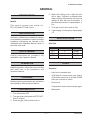
SERVICE MANUAL
EF SERIES
GAS FRYERS
MODELS
EF3
EF4
EF5
ML-52099
ML-114943
ML-114944
- NOTICE This manual is prepared for the use of trained Vulcan Service
Technicians and should not be used by those not properly qualified.
If you have attended a Vulcan Service School for this product, you
may be qualified to perform all the procedures described in this
manual.
This manual is not intended to be all encompassing. If you have not
attended a Vulcan Service School for this product, you should
read, in it's entirety, the repair procedure you wish to perform to
determine if you have the necessary tools, instruments and skills
required to perform the procedure. Procedures for which you do
not have the necessary tools, instruments and skills should be
performed by a trained Vulcan Service Technician.
Reproduction or other use of this Manual, without the express
written consent of Vulcan, is prohibited.
For additional information on Vulcan-Hart or to locate an authorized parts
and service provider in your area, visit our website at www.vulcanhart.com
VULCAN-HART
DIVISION OF ITW FOOD EQUIPMENT GROUP, LLC
P.O. BOX 696, LOUISVILLE, KY 40201-0696
TEL. (502) 778-2791
WWW.VULCANHART.COM
F-35641 (2-05)
EF SERIES GAS FRYERS
CONTENTS
GENERAL .......................................................................................................................................... 3
INTRODUCTION ........................................................................................................................ 3
Models ................................................................................................................................ 3
INSTALLATION .......................................................................................................................... 3
OIL FILTERING .......................................................................................................................... 3
OPERATION .............................................................................................................................. 3
CLEANING ................................................................................................................................. 3
LIGHTING PILOT ....................................................................................................................... 3
SPECIFICATIONS ..................................................................................................................... 3
Gas Data ............................................................................................................................ 3
TOOLS ....................................................................................................................................... 3
Standard ............................................................................................................................. 3
REMOVAL AND REPLACEMENT OF PARTS .................................................................................. 4
COVERS AND PANELS ............................................................................................................ 4
Door .................................................................................................................................... 4
Heat Shield ......................................................................................................................... 4
BURNERS .................................................................................................................................. 5
THERMOSTAT ........................................................................................................................... 5
HIGH LIMIT ................................................................................................................................ 7
THERMOPILE ............................................................................................................................ 8
PILOT ORIFICE ......................................................................................................................... 9
PILOT ......................................................................................................................................... 9
COMBINATION VALVE ............................................................................................................ 10
FRY TANK ................................................................................................................................. 11
SERVICE PROCEDURES AND ADJUSTMENTS ........................................................................... 12
MILLIVOLT CONTROLS TEST ................................................................................................ 12
THERMOSTAT CALIBRATION ................................................................................................ 12
Calibration Steps .............................................................................................................. 12
PILOT ADJUSTMENT .............................................................................................................. 13
BURNERS, NOZZLES AND ORIFICES .................................................................................. 13
Burners ............................................................................................................................. 13
Nozzles and Orifices ........................................................................................................ 13
COMBINATION VALVE REGULATOR ADJUSTMENT ............................................................ 14
ELECTRICAL OPERATION ............................................................................................................. 16
CONTROL SYSTEM DESCRIPTION ...................................................................................... 16
SYSTEM CONDITION QUICK CHECK PROCEDURES ......................................................... 17
SCHEMATIC ............................................................................................................................ 17
COMPONENT FUNCTION ...................................................................................................... 17
TROUBLESHOOTING ..................................................................................................................... 18
F35641 (02-05)
—2—
EF SERIES GAS FRYERS
GENERAL
4. While still holding knob in light the pilot
with a taper. Continue to depress knob
(approximately 30 seconds) until the pilot
remains lit after the knob is released. If
pilot does not remain lit, repeat steps 2, 3
& 4.
INTRODUCTION
Models
This service manual was written for:
EF3, EF4 and EF5 Gas Fryers.
5. Turn gas control valve knob to ON.
6. If gas supply is interrupted, repeat steps
1-5.
INSTALLATION
Generally, installations are made by the dealer
or contracted by the dealer or owner. Detailed
installation instructions are included in the
Installation and Operation Manual, which is
sent with each fryer.
SPECIFICATIONS
Gas Data
OIL FILTERING
Filtering instructions are included in the
Installation and Operation Manual.
MODEL
NO. TUBES
BTU/HR
EF3
EF4
EF5
3
4
5
90,000
120,000
150,000
TOOLS
OPERATION
Detailed operation instructions are included
with each fryer in the Installation and
Operation Manual.
Standard
CLEANING
Detailed cleaning procedures are included in
the Installation and Operation Manual.
LIGHTING PILOT
•
Hand tools (standard set)
•
VOM with AC current tester (any quality
VOM with a sensitivity of at least 29,000
ohms per volt can be used)
•
Gas test kit
•
Temperature tester (thermocouple type)
•
Manometer
1. Turn thermostat OFF.
2. Turn gas control valve knob to OFF/PILOT.
Wait 5 minutes.
3. Push the gas control valve knob in.
—3—
F35641 (02-05)
EF SERIES GAS FRYERS
REMOVAL AND REPLACEMENT OF PARTS
Heat Shield
COVERS AND PANELS
1. Remove screws holding heat shield in
place (Figure 2).
WARNING: SHUT OFF THE GAS BEFORE
SERVICING.
Door
1. While holding onto the door remove (2)
screws securing the door hinge to the
fryer bottom front flange (Figure 1).
Figure 2
Figure 1
2. Remove heat shield.
2. Prepare to catch door assembly. Once
screws and hinge are removed, the door
will drop off into your hand(s).
3. Reinstall door assembly by reversing
steps 1 & 2 above.
F35641 (02-05)
—4—
EF SERIES GAS FRYERS
BURNERS
WARNING: SHUT OFF THE GAS BEFORE
SERVICING.
1. Remove heat shield as outlined under
Cover and Panels. (Optional)
2. Loosen the two mounting bolts at the top
of each burner (Figure 3).
Figure 4
4. Reverse the procedure to install.
THERMOSTAT
WARNING: SHUT OFF THE GAS BEFORE
SERVICING.
1. Drain shortening from fry tank.
2. Remove heat shield as outlined under
Covers and Panels.
Figure 3
3. Push burner up while pulling the bottom
of the burner forward to clear the burner
nozzle (Figure 4).
3. Remove left burner as outlined under
Burners.
4. Remove thermostat knob by pulling knob
off thermostat shaft.
—5—
F35641 (02-05)
EF SERIES GAS FRYERS
7. Loosen the packing nut and holding nut
(Figure 7).
5. Remove thermostat mounting screws and
remove thermostat from mounting bracket
(Figure 5).
Figure 7
8. Remove the thermostat bulb from the
clamp (Figure 8).
Figure 5
6. Remove wire leads from the rear of the
thermostat, noting all connections for
reassembly (Figure 6).
Figure 8
9. Pull the thermostat bulb through the
underside of the fry tank and remove the
thermostat assembly.
Figure 6
F35641 (02-05)
—6—
EF SERIES GAS FRYERS
6. Loosen the packing nut and the holding
nut (Figure 10).
10. Reverse the procedure to install. When
installing the new thermostat assembly,
do not kink the thermostat capillary. Wrap
threads of packing nut with Teflon tape to
prevent leakage.
HIGH LIMIT
WARNING: SHUT OFF THE GAS BEFORE
SERVICING.
1. Drain shortening from fry tank.
2. Remove heat shield as outlined under
Covers and Panels.
3. Remove wire leads from high limit, noting
all connections for reassembly (Figure 9).
Figure 10
7. Remove the high limit bulb from the clamp
(Figure 11).
Figure 9
4. Remove high limit from mounting bracket.
5. Remove left burner as outlined under
Burners.
Figure 11
—7—
F35641 (02-05)
EF SERIES GAS FRYERS
8. Pull the high limit bulb through the
underside of the fry tank and remove the
high limit.
9. Reverse the procedure to install. When
installing the new high limit assembly, do
not kink the high limit capillary. Wrap
threads of packing nut with Teflon tape to
prevent leakage.
THERMOPILE
WARNING: SHUT OFF THE GAS BEFORE
SERVICING.
WARNING: ALL GAS JOINTS DISTURBED
DURING SERVICING MUST BE CHECKED
FOR LEAKS. CHECK WITH SOAP AND
WATER SOLUTION (BUBBLES). DO NOT
USE AN OPEN FLAME.
1. Remove the screw securing the Pilot/
Thermopile Assembly Bracket to the tank
front. Lower the assembly away from the
tank (Figure 12).
2. Disconnect thermopile lead wires as
outlined under High Limit.
Figure 12
F35641 (02-05)
—8—
EF SERIES GAS FRYERS
3. Remove thermopile from pilot bracket by
loosening the holding nut (Figure 13).
PILOT
WARNING: SHUT OFF THE GAS BEFORE
SERVICING.
WARNING: ALL GAS JOINTS DISTURBED
DURING SERVICING MUST BE CHECKED
FOR LEAKS. CHECK WITH SOAP AND
WATER SOLUTION (BUBBLES). DO NOT
USE AN OPEN FLAME.
1. Remove the screw securing the Pilot/
Thermopile Assembly Bracket to the tank
front. Lower the assembly away from the
tank (Figure 12).
2. While holding assembly in the palm of
your hand remove the pilot compression
fitting at the bottom of the pilot and
disconnect the pilot tubing (Figure 12).
Figure 13
3. Remove thermopile as outlined under
Thermopile (set aside for reassembly).
4. Reverse procedure to install.
4. Remove (2) screws holding the pilot
assembly to the Pilot/Thermopile
Assembly Bracket and replace the old
pilot with the new assembly (Figure14).
PILOT ORIFICE
WARNING: SHUT OFF THE GAS BEFORE
SERVICING.
WARNING: ALL GAS JOINTS DISTURBED
DURING SERVICING MUST BE CHECKED
FOR LEAKS. CHECK WITH SOAP AND
WATER SOLUTION (BUBBLES). DO NOT
USE AN OPEN FLAME.
1. Remove the screw securing the Pilot/
Thermopile Assembly Bracket to the tank
front. Lower the assembly away from the
tank (Figure 12).
2. While holding assembly in the palm of
your hand remove the pilot compression
fitting at the bottom of the pilot to expose
the orifice (Figure 12).
3. Replace orifice and reverse procedure to
assemble.
Figure 14
5. Reinstall by reversing steps 1-4.
—9—
F35641 (02-05)
EF SERIES GAS FRYERS
6. Disconnect combination valve union and
pressure fitting (Figure 16).
COMBINATION VALVE
WARNING: SHUT OFF THE GAS BEFORE
SERVICING.
WARNING: ALL GAS JOINTS DISTURBED
DURING SERVICING MUST BE CHECKED
FOR LEAKS. CHECK WITH SOAP AND
WATER SOLUTION (BUBBLES). DO NOT
USE AN OPEN FLAME.
1. Disconnect fryer from main gas supply.
2. Remove heat shield as outlined under
Covers and Panels. (Optional)
3. Remove right burner as outlined under
Burners.
4. Disconnect wire leads from the
combination valve and mark for
reconnecting.
5. Disconnect pilot tubing from combination
valve (Figure 15).
Figure 16
7. Remove the combination valve from the
fryer.
8. Remove all pipe fittings from the old
combination valve if the new valve is not
supplied with fittings.
9. Reverse procedure to install using original
pipe fittings.
Figure 15
F35641 (02-05)
— 10 —
EF SERIES GAS FRYERS
7. Remove the manifold bracket from the
tank assembly by removing the (4) bolts
(Figure 18).
FRY TANK
WARNING: SHUT OFF THE GAS BEFORE
SERVICING.
WARNING: ALL GAS JOINTS DISTURBED
DURING SERVICING MUST BE CHECKED
FOR LEAKS. CHECK WITH SOAP AND
WATER SOLUTION (BUBBLES). DO NOT
USE AN OPEN FLAME.
1. Disconnect fryer from main gas supply.
2. Remove baskets, fryer basket hanger and
crumb screen.
3. Drain oil from tank.
4. Remove heat shield as outlined under
Covers and Panels.
Figure 18
5. Remove screws holding fryer tank
(Figure 17).
8. Remove thermostat and high limit as
outlined under Thermostat and High Limit.
9. Remove the screw securing the Pilot/
Thermopile Bracket Assembly (Figure 19).
Figure 17
6. Remove burners as outlined under
Burners.
Figure 19
10. Lift the fry tank up and out of cabinet.
Carefully place the tank assembly on the
floor (this procedure requires two people).
11. Remove the tank ball drain valve
(Figure 18).
12. Reverse the procedure to install new tank.
— 11 —
F35641 (02-05)
EF SERIES GAS FRYERS
SERVICE PROCEDURES AND ADJUSTMENTS
MILLIVOLT CONTROLS TEST
1. Verify proper gas (natural or propane) is
present.
7. Turn gas control valve knob to ON. Turn
thermostat to a setting higher than the
shortening temperature.
A. If the voltage measures 150 millivolts
or more but the burners do not ignite,
replace the combination valve.
2. Check for correct wiring and secure
connections.
B. If the voltage is less than 150 millivolts,
measure the voltage between
terminals NO of the high limit and PG
of the combination valve.
3. Verify the pilot flame is adjusted properly
as outlined in Pilot Adjustment.
4. If the pilot is not lit, light pilot as outlined
under Lighting Pilot. Allow the pilot to
burn for 3 to 4 minutes to stabilize.
1) If the voltage is 200 millivolts or
greater, replace the thermostat.
A. If the pilot remains lit, proceed to
step 6.
2) If the voltage is less than 200
millivolts, replace the combination
valve.
B. If the pilot will not remain lit, proceed
to step 5.
5. Connect DC voltmeter to terminals
TH-PG and PG of combination valve.
Relight the pilot, hold the gas control
valve knob in and allow the pilot to burn
for 3 to 4 minutes to stabilize.
A. lf the voltage measures 450 millivolts
or greater and the pilot will not stay lit,
replace the combination valve.
B. lf the voltage is less than 450 millivolts,
measure the voltage at terminals NO
and C of high limit.
THERMOSTAT CALIBRATION
1. Place temperature tester in the fry tank
near the thermostat bulb.
2. Set the thermostat to 300°F and allow the
temperature to stabilize.
3. Check the temperature tester reading
against the thermostat dial reading. If
there is a variance of more than ±20°F
(280°F to 320°F), calibration is required.
1) If the voltage is 500 millivolts or
more, replace the high limit.
Calibration Steps
2) If the voltage is less than 500
millivolts, disconnect the lead wire
from terminal TH-PG of the
combination valve and remeasure
voltage at the high limit.
1. Remove thermostat knob from shaft.
a. If the voltage is less than 500
millivolts, replace the thermopile.
b. If the voltage is 500 millivolts or
more, replace the combination
valve.
6. Connect DC voltmeter to terminals PG
and TH of combination valve.
F35641 (02-05)
2. Using a small screwdriver, rotate the
setscrew inside the hollow shaft
counterclockwise to increase the
temperature or clockwise to decrease the
temperature (1/4 turn equals approximately 18°F).
3. Allow temperature to stabilize and recheck
temperature. Repeat until the temperature
falls within the limits as stated in step 3
under Thermostat Calibration.
4. Install thermostat knob and set dial to
350°
— 12 —
EF SERIES GAS FRYERS
5. Allow temperature to stabilize at new
setting and compare temperature tester
to dial setting. Recalibrate if the
temperature does not fall within the range
of 330°F to 370°F.
6. If the temperature does not fall within the
limits at both settings, replace the
thermostat.
PILOT ADJUSTMENT
1. Light pilot as outlined under Lighting Pilot.
Figure 21
2. If the flame does not extend beyond the
outer edges of the pilot shield 1/2”, or
extends more than 1/2”, (Figure 20), an
adjustment is necessary.
BURNERS, NOZZLES
AND ORIFICES
WARNING: SHUT OFF THE GAS BEFORE
SERVICING.
Burners
If the burner ports become clogged, the fryer
will not operate properly. If the burner is
cracked, it must be replaced.
1. Remove burner(s) as outlined under
Burners.
2. Check burner(s) for cracks and clogged
ports.
Figure 20
3. Remove the cap covering pilot adjustment
screw, (Figure 21). Turn the recessed
pilot adjustment screw counterclockwise
to increase the size of the flame or
clockwise to decrease the size of the
flame.
3. If the ports are clogged, wash burner(s) in
warm, soapy water. If this does not remove
obstructions, a #37 drill bit can be used
(do not use in an electric drill; hand-turn
only).
Nozzles and Orifices
1. Remove the burners as outlined under
Burners.
— 13 —
F35641 (02-05)
EF SERIES GAS FRYERS
2. Hold the burner nozzle with channel locks
and remove the orifice, (Figure 22). Check
the orifice for obstructions or damage.
1. Turn the gas control valve knob to OFF
(Figure 23).
Figure 23
2. Remove the plug from the submanifold
and install pressure gauge at this point
(Figure 24).
Figure 22
3. If the orifice is clogged, wash the orifice in
warm, soapy water. If this does not remove
obstructions, a #37 drill bit can be used
(do not use in an electric drill; hand-turn
only).
4. With channel locks, remove the burner
nozzle (Figure 22).
5. Reverse procedure to install new burner
nozzle and orifice.
COMBINATION VALVE
REGULATOR ADJUSTMENT
WARNING: SHUT OFF THE GAS BEFORE
SERVICING.
Accurate gas pressure adjustments can only
be made with the gas on and the burner lit. If
the incoming line pressure to the valve is less
than the minimum stated, then the pressure
cannot be set correctly.
Figure 24
3. Turn on the gas and light the pilot as
outlined under Lighting Pilot.
4. Turn the gas control valve knob to ON.
5. Set the thermostat so the burners will
come on.
The combination valve is preadjusted for
natural or propane gas as specified on the
rating plate. The natural gas rating is 4” W.C.,
and the propane rating is 10" W.C.
F35641 (02-05)
— 14 —
EF SERIES GAS FRYERS
6. Read the pressure gauge. The manifold
pressure reading should match the
pressure rating on the data plate.
A. To adjust, remove the cap covering
the manifold pressure adjustment
screw (Figure 25). Turn the recessed
manifold pressure adjustment screw
counterclockwise to decrease
pressure or clockwise to increase
pressure.
Figure 25
7. Install the cap and check for proper
operation.
— 15 —
F35641 (02-05)
EF SERIES GAS FRYERS
ELECTRICAL OPERATION
C. When the thermostat calls for heat
(closed circuit) power from the
thermopile is then connected to the
other combination valve thermostat
connection through wire 2.
CONTROL SYSTEM
DESCRIPTION
1. The thermopile (PG) provides the total
control voltage for this system.
D. If the high limit trips, the thermopile is
connected across zero ohms, the
output voltage of the thermopile drops
to 0.0 millivolts, and the thermostat
coil of the combination valve drops
out, shutting the thermostat valve.
A. One side of the thermopile is
connected to the common (C) of the
high limit (HL).
B. The other side of the thermopile is
connected to the normally open (NO)
contacts of the high limit.
3. Total Shutdown.
C. The common of the high limit (below
the high limit trip temp.) is connected
through the normally closed (NC)
contacts of the high limit, through wire
3 to the combination valve pilot
connection common.
D. The other side of the pilot valve is
connected through wire 4 to wire 1 to
the high limit normally open contacts
which hold the pilot valve open.
1) If the high limit trips, connection is
made from the common to the
normally open contacts, turning
off pilot valve voltage. The gas
valve closes.
2. Thermostat Control.
A. One side of the millivolt supply is
connected through the high limit
system, as described above, to the
thermostat common (wire 3) of the
combination valve.
B. The other side of the thermopile is
connected from the normally open
contacts of the high limit to the
thermostat through wire 1.
F35641 (02-05)
— 16 —
A. When the high limit trips, 0.0 millivolts
will read across both coils of the
combination valve, causing both
valves to close.
B. Pilot relight cannot be accomplished
until oil cools sufficiently to allow high
limit to close.
C If any wire in the system is cut or
broken, the system will shut down.
EF SERIES GAS FRYERS
SYSTEM CONDITION QUICK
CHECK PROCEDURES
SCHEMATIC
1. Use the Pilot Lighting procedure and
check millivolts (mV) at wires 3 and 4.
A. lf the pilot lights, then pilot combination
valve and high limit are good.
B. If the pilot will not stay lit, check high
limit and open the thermopile circuit. It
should read 300 mV; if there are Ø
volts, check high limit. If the high limit
is good, replace combination valve.
C. Check for voltage at disconnected
thermopile. It should read 300 mV; if
there are Ø volts, replace thermopile.
Check high limit. If the high limit is
good, replace combination valve.
2. Turn on thermostat; burners should light.
A. lf the burner does not light, check the
following:
1) Voltage at combination valve at
wires 2 and 4.
Figure 26
2) If correct voltage is present, then
check combination valve.
3) If there are Ø volts, check voltage
between wire 3 of combination valve
and wire 1 of thermostat. If correct
voltage is present, then check
resistance of the thermostat
contacts and continuity of wires
3 & 2.
COMPONENT FUNCTION
•
Thermostat - Millivolt type with capillary
bulb, single-throw break on temperature
rise. Temperature range of 200°F to
400° F.
•
Thermopile - Millivolt control with 24"
capillary. Rated to generate 500 millivolts.
•
Combination Valve - Regulates gas flow
to burner and pilot. Provides pilot safety.
•
High Limit - Prevents overheating of fryer
in the event of thermostat failure. Opens
at 465°F and automatically resets at
415°F.
— 17 —
F35641 (02-05)
EF SERIES GAS FRYERS
TROUBLESHOOTING
SYMPTOM
The temperature of the
shortening drops, or
excessive recovery time is
required.
Pilot won’t stay lit. Fryer
shuts off.
Rapid shortening
breakdown, crumbs and
specks in frying compound.
CAUSE
Insufficient gas supply to
unit.
REMEDY
Adjust gas supply at gas combination
valve.
Ventilation system pulling
Relocate fryer.
heat out of heat exchanger
and flue box.
Overloading fryer capacity.
Malfunctioning thermopile
or loose/dirty connection in
thermopile.
Adjust loads accordingly.
Check thermopile function and
connections. Adjust or replace as
required.
Malfunctioning shutoff
valve.
Replace shutoff valve.
Pilot burner orifice and air
openings need cleaning.
Excessive temperature
settings (over 375° F).
Clean burner orifice and air openings
as required.
Adjust temperature setting.
Shortening not being
filtered regularly.
Adjust filtering schedule.
Incorrect preparation of
breaded food.
Do not use salt.
Allow breading time to adhere to food.
Do not allow loose flour to fall into
shortening from hands.
Do not add strainings or drippings
from meat fats to shortening.
Use correct shortening and follow
temperature recommendations.
Take out 10% to 15% of the
shortening.
Check thermostat settings with
thermometer periodically.
F35641 (02-05)
— 18 —
EF SERIES GAS FRYERS
SYMPTOM
Leaking tank.
Pilot burner flames
adjusted properly, but
fluctuates to very low and
blows out easily.
CAUSE
REMEDY
Foam-over by depleted
shortening permits oil to
drip from the tank surface,
giving appearance of
leaking.
Replace shortening.
Careless draining
procedures.
Gas control valve knob should be in
PILOT or OFF position before
draining oil. Burners heating an empty
tank will damage tank joints.
Carbon buildup causes
Clean tank surfaces.
rapid attack on tank by
promoting acid formulation.
Gas pressure too low.
Check gas pressure on submanifold
fitting when fryer is in operation.
Gas pressure too low at
submanifold.
Check other equipment attached to
same gas line.
Adjust gas pressure at submanifold to
not less than 4.0” W.C. (natural and
mixed gas) or 10.0” W.C. for propane
gas.
— 19 —
F35641 (02-05)
F35641 (02-05)
PRINTED IN U.S.A.