1
Nova
Power From The Heavens
PA-600
Professional Amplifier
Operation Manual
& Technical Guide
POWER
SIGNAL
PROTECT PEAK
SIGNAL
MIN
MONO
PEAK PROTECT
CH 2
LEVEL
CH1
LEVEL
MAX
MIN
MAX
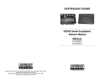
2 CHANNELS / 600 WATTS PROFESSIONAL BRIDGEABLE AMPLIFIER
VOLTAGE SELECT
230V
115V
SPEAKER OUTPUT
CH 2
LINE LEVEL INPUT
CH 2
CH 1
CH 1
CH1
+ CH 2 120W/8 Ohm
200W/4 Ohm
+ CH 1 120W/8 Ohm
200W/4 Ohm
CH 2
M A N U F A C T U R E D B Y E A R T H Q U A K E S O U N D C O R P O R A T I O N.
BRIDGED(MONO)
400W/8 Ohm
FUSE
T3.15A~230V/50Hz
T6.3A~115V/60Hz
230VAC,50Hz
115VAC,60Hz
750W
Earthquake Sound Corporation. 2727 Mc Cone Avenue, Hayward, CA 94545. www.earthquakesound.com.
DEAR VALUED CUSTOMER.
channel @ 4 ohms stereo mode or 110 watts per channel @ 8 ohms (stereo mode); 560 watts
@ 4 ohms, 380 watts @ 8 ohms (bridged mono mode). Several "professional" features, such
as 1/4" and XLR input jacks with electronically balanced Low or Medium impedance
operation have been built into the amplifier. Limiting circuitry with LED indicators
constantly monitors the output level of each channel and provides protection from clipping,
thus preventing the generation of speaker-damaging square waves. A built-in protection
circuit protects the amplifier from overloads, short circuits, and overheating. In addition,
each channel features a Signal LED to assist in hookup and troubleshooting and a Fault
LED which indicates when the internal protection circuitry is activated.
Earthquake Sound Corporation specializes in manufacturing high end Home and Car
audio products ranging from the smallest driver to the loudest subwoofer system. In its
dedication to excellence, Earthquake has maintained extensive programs in research and
development to provide you with the highest quality audio products.
The PA-600 is a ruggedly constructed high quality professional amplifier. The amplifier
mounts into a standard 19" rack, requiring only two rack spaces (3-1/2 inches, vertically).
Two automatic variable-speed internal cooling fans use the sides, rear and the front of the
amplifier - not the top and bottom - for its air intake and exhaust, allowing you to stack
multiple amplifier closer together in a rack mount situation. Additional rack support holes
have been provided along the rear of the amplifier for the most secure installation
possible. (Use of these additional supports is strongly recommended.)
This owners manual is designed to better acquaint you with the PA-600 proamplifier. It is imperative that you read this manual in its entirety. EARTHQUAKE
technicians and staff are looking forward to answer any questions you might have, please
call (1-800-576-7944).
The PA-600 produce up to 300 watts of power per channel @ 2 ohms, 200 watts per
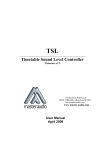
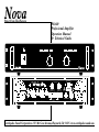
SOUND LEVEL
DBA
90
92
95
97
10 0
10 2
10 5
11 0
11 5
DURATIO N
IN HOURS
8
6
4
3
2
1 - 1 1/ 2
1
1/ 2
1/ 4 or less
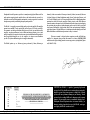
THE CHART (ON THE SIDE) SHOWS THE U.S. GOVERNMENTS
OCCUPATIONAL SAFETY AND HEALTH ADMINISTRATION (OSHA)
REGULATIONS WHICH WERE IN EFFECT AT THE TIME OF THIS
PUBLICATION FOR PERMISSIBLE NOISE EXPOSURE,
PER 29CFR1910.95, TABLE G-16.
Specifications & features are subject to change without notice.
-3-
CAUTION: the PA-600 is capable of generating high sound
pressure levels. You should exercise caution when operating this
amplifier system. Long term exposures to high levels of sound
pressure will cause permanent damage to your hearing. Sound
pressure levels exceeding 85dB can be dangerous with constant
exposure. Set your audio system to a comfortable loudness level.
Earthquake Sound Corporation does not assume liability for
damages resulting from the direct use of the PA-600 , and urges
users to play the PA-600 in moderate levels.
www.earthquakesound.com
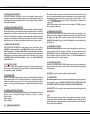
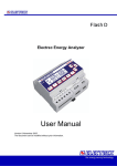
PA-600 AMPLIFIER FRONT & REAR PANELS FUNCTIONS/CONNECTION.
4
5
6
6
5
POWER
SIGNAL
PROTECT PEAK
SIGNAL
MIN
MONO
PEAK PROTECT
CH 2
LEVEL
CH1
LEVEL
MAX
MIN
MAX
2 CHANNELS / 600 WATTS PROFESSIONAL BRIDGEABLE AMPLIFIER
7
1
8
18
11
9
12
2
10
11
12
14
14
13
13
3
16
15
7
17
1. POWER SWITCH:
4. POWER INDICATOR LED:
This switch turns the amplifier on in the up position ("I" pressed in ) and off in the down
position. When AC power is applied to the amplifier, the power indicator led (#4)
illuminates.
This Led illuminates when AC power is applied by means of the Power Switch (#1)
5. PROTECT INDICATOR LED'S:
These LED's illuminate whenever the internal protection relay for the channel is activated.
The protection relay is activated for a short period upon initial turn-on and at turn-off to
prevent transient "spikes" from being reproduced through your speakers. A protect condition
is also indicated if the unit gets too hot, or if DC voltages are present at the output. During
thermal protection, both channels are shut down. In the event of DC voltage on the output,
only the affected channel will be disconnected. The circuitry associated with the LED
indicators provides valuable protection for both the amplifier and your speakers.
2. LEVEL CONTROL (CH-1) & MONO:
This rotary potentiometer controls the sensitivity or gain of (CH-1). Set them to the level
needed for the desired output. When amplifier is set in the bridge mono mode, only this level
control (CH-1) is active in this mode.
3. LEVEL CONTROL CH2:
This rotary potentiometer controls the sensitivity or gain of CH2. Set them to the level
needed for the desired output. When amplifier is set in the bridge mono mode, this level
control is not active.
Specifications & features are subject to change without notice.
-4-
www.earthquakesound.com
PA-600 AMPLIFIER FRONT & REAR PANELS FUNCTIONS/CONNECTION.
These jacks accept line level signal sources by means of cables fitted with standard ¼” phone
plugs. Low or medium impedance balanced or unbalanced sources are acceptable for these
inputs. Balanced inputs are wired as follows: Tip = Signal (+), Ring = Signal (-), Sleeve
= Ground. Unbalanced inputs may be wired: Tip = Signal, Sleeve = Ground, using a
“mono” plug.
NOTE: The input channel circuitry requires a line level signal of 1.1V RMS or greater to
drive the amplifier to full output.
6. SIGNAL INDICATOR LEDS:
These LED's illuminate when signal is detected at the amplifier's output terminals,
providing accurate visual confirmation of signal presence, which is helpful in hookup, and
troubleshooting. The output signal must be at least 5% of the amplifier's full rated output to
make the LED's illuminate.
7. COOLING FAN EXHAUST VENT:
The PA 600 employs a pair of variable-speed internal cooling fans to draw air through the
unit and keep it running cool even under extreme operating conditions. The air is drawn in
through the unit's side and rear intake vents and is forced out through the front panel
exhaust vent. This method of cooling draws air out from the interior of the rack and provides
more efficient cooling methods, which bring air in from the front and exhaust it through the
back. Keep these vents clear and free from obstruction at all times to insure proper cooling.
13. BINDING POST OUTPUT:
These output connectors offer an excellent method of connecting the amplifier to your
speakers using cables terminated with spade lugs, banana plugs, or bare wire. When using
the amplifier in the Mono Mode, you must use either the two red binding posts or the
BIAMP/MONO (middle) Phone jack (#13). The Binding Posts are wired in parallel with
the Phone Jacks.
8. STEREO / MONO SWITCH:
14. SPEAKER OUT JACKS:
This switch connects the channels to work together for more power output. In the
“STEREO” position the amplifier is in the STEREO MODE; with the switch in “MONO”
MODE the amplifier is in the Bridge MONO MODE. In the Bridge Mono Mode, connect
input to Channel 1(Channel 2's inputs are disconnected.) Both amp channels are internally
bridged together to create a single-channel amplifier of increased output power. Use the two
red BINDING POSTS (labeled ”Mono/Biamp”) or pins 1+/2+ of the BIAMP/MONO
(middle) Phone jack.
These heavy-duty output jacks are to be used to connect the amplifier to your speakers using
cables terminated with Phone type plugs. These jacks are wired in parallel with the
BINDING POSTS: channel 1 and 2 Phone Jacks are wired with pin#1(+) positive or “in
phase”, and pin#1(-) ground or “out of phase" (wired 1+ 1-). The MONO /BIAMP jack has
channel 1 wired to 1+ and 2+, with 1+ "in phase”.
15. VOLTAGE SELECTOR:
9. NEW AUTO ON / OFF:
Selection of AC 115V/60Hz or AC 230V/50Hz voltage source. Before connecting the power
plug to the wall AC outlet, make sure your local power line AC voltage matches the voltage
setting of amplifier.
The new auto sensing circuitry immediately senses signal as it reaches the amplifier, when
the music stops it will automatically fall asleep. While in sleep mode the PA-600 consumes
less energy than commonly sold Pro Amps.
16. FUSE: Use only the type of fuse specified on the back of amplifier.
10. LIMIT SWITCH:
Switch to “ON” position to activate the limit circuit to prevent the amplifier from clipping.
Signal indicator LED's will all be illuminated whenever the input signal attempts to
overdrive the amplifier's output section. Not only does clipping produce harsh sounding
distortion, it is also capable of damaging speaker components-particularly high frequency
drivers.
This heavy duty power cord must be connected to a grounded Ac outlet of the proper voltage
for the amplifier to operate. TO REDUCE THE RISK OF ELECTREC SHOCK, DO
NOT REMOVE OR BYPASS THE GROUND PRONG OF THE POWER CORD.
11. XLR BALANCED INPUT JACKS:
PA-600 amplifier.
17. POWER CORD:
18. RCA INPUT: this is the simplest / most common way to drive an audio signal into the
These jacks will accept any balanced or unbalanced low or medium impedence line level
source by means of a three-pin XLR plug. The wiring for the plug is as follows:
Pin#1=Ground,
Pin#2=Signal (+),
Pin#3= Signal (-).
NEW:
Ultra sensitive input pre-amp stage circuitry. Some products on the market can produce
enough voltage to drive an amp but most don't. Earthquake increased sensitivity by giving
you more output with less input signal. This new circuitry will allow you to drive the amp to
full stage with as little as 60milivolt.
12. ¼” PHONE JACK INPUTS:
Specifications & features are subject to change without notice.
-5-
www.earthquakesound.com
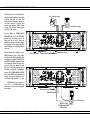
PA-600 AMPLIFIER CONNECTION (STEREO & MONO)
The PA-600 can be used in Stereo Mode as
two separate power amplifiers, each capable
of driving loads down to 2 ohms. Each
channel operates independently and has its
own input connectors, sensitivity level
controls, signal indicator LEDS, limiter
circuitry, fault protection circuitry, power
amp, and speaker outputs.
2 to 8 ohms range
2 to 8 ohms range
In Stereo Mode, the STEREO/MONO
SWITCHE must be in the "STEREO"
position. Either the binding posts or the
Phone jacks may be used to connect the
amplifier to the speakers. Both inputs must be
active (plugged) in stereo mode; either XLR
input, RCA input, or the Phone Jack input
can be used.
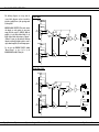
The two internal power amplifiers may be
bridged together to form a single, higherpowered amp. In the Bridged Mono Mode,
the amplifier uses channel #1 INPUT jacks
and LEVEL CONTROL; channel #2 inputs
are disconnected. Channel #2 power amp
receives its signal from channel #1 input
This signal is connected to channel 2 prior to
its Limiter, so each channel is independently
protected. The STEREO/MONO SWITCH
must be in the MONO position. Because both
channels are being used (bridged in series),
the minimum load impedance is 4 ohms.
From audio source
From audio source
The RED binding post terminals (ch
1="+", ch 2=" + ") or the middle Phone jack
(ch #1) must be used to connect the amplifier
to the speakers.
From audio source
4 to 8 ohms range
NOTE: Use both
Red Terminals ONLY
in Mono Mode
Specifications & features are subject to change without notice.
-6-
www.earthquakesound.com
PA-600 AMPLIFIER OPERATION
The following diagrams are excerpts from the
system block diagrams and are intended to
provide a simplified view of the operating modes
of the amplifier.
BRIDGE MONO SWITCH: This switch connects
the channels to work together for more power
output. With the switch in "MONO" Mode the
amplifier is in the Bridge Mono Mode. In the
Bridge Mono Mode, connect input to Channel 1
(Channel 2's inputs are disconnected). Both amp
channel are internally bridged together to create a
single-channel amplifier of increased output power.
Use the two red BINDING POSTS (labeled
"Mono/Biamp") or pins 1+/2+ of the
BIAMP/MONO (middle) Phone jack.
Stereo Mode:
RCA#2
RING
TIP
2
CH 2
INPUTS
CH 2
STEREO LEVEL
3
+
STEREO
1
PARALLEL
MONO
BRIDGE
MONO
STEREO
CH 2
AMP
BRIDGE
MONO
1+
BRIDGE
MONO
CH 2 OUTPUTS
2-
RCA#1
RING
1+
TIP
2
CH 1
INPUTS
2-
CH 1
LEVEL
CH 1
AMP
CH 1 OUTPUTS
3
+
1
Bridge Mono Mode:
RCA#2
RING
TIP
2
CH 2
INPUTS
CH 2
STEREO LEVEL
3
+
STEREO
1
PARALLEL
MONO
BRIDGE
MONO
BRIDGE
MONO
STEREO
BRIDGE
MONO
CH 2
AMP
1+
CH 2 OUTPUTS
2-
RCA#1
RING
1+
TIP
2
CH 1
INPUTS
CH 1
LEVEL
2-
CH 1
AMP
CH 1 OUTPUTS
3
+
1
Specifications & features are subject to change without notice.
-7-
www.earthquakesound.com
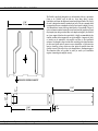
PA-600 AMPLIFIER INSTALLATION & MOUNTING
17.06"
433.3mm
The PA-600 is specifically designed to be rack mounted, either as a permanent
fixture or in a "mobile" rack. As with any large, heavy object, a proper
installation could mean the difference between success and disaster. The front of
the unit is designed to attach to standard rack rails. The four outermost holes
correspond to the screw on standard rack rails (2 rack spaces in height). Use only
10-32 threaded rack screws with large heads (such as a truss heads). The use of
nylon rack mount washers between the screw heads and the faceplate will keep
the faceplate from being scratched. Due to the depth and weight of the PA-600 a
set of rear support holes have been provided. It is highly recommended that the
installer use these holes to support the rear of the amplifier. A support rail, shelf,
or bracket can be attached to the amplifier and then to the installation
enclosure. One thought to keep in mind when considering the related hardware
for this: more is better when it comes to a secure installation - a little extra time
spent on installing a heavy object more than offsets the possible losses that
could be incurred if the object were to be damaged due to inadequate support.
The dimensions below are provided to assist you and/or your installation
engineer in mounting the amplifier securely.
1.85"
46.9mm
3.49"
88.8mm
INDICATES CENTER OF GRAVITY
15.43"
392mm
1.54"
39.1mm
19.00"
482.6mm
Specifications & features are subject to change without notice.
-8-
www.earthquakesound.com
PA-600 AMPLIFIER SPECIFICATIONS
POWER OUTPUT
2 x 120 watts RMS @ 8 ohms 20Hz-20kHz (stereo mode)
2 x 200 watts RMS @ 4 ohms 20Hz-20kHz (stereo mode)
2 x 300 watts RMS @ 2 ohms 1kHz (stereo mode)
380 watts RMS @ 8 ohms 20Hz-20kHz (mono mode)
600 watts RMS @ 4 ohms 1kHz (mono mode)
FREQUENCY RESPONSE
+0/-0.5dB, 20Hz-20kHz
TOTAL HARMONIC DISTORTION
<0.05%, 20Hz-20kHz
SLEW RATE
40 volts / microsecond
SIGNAL TO NOISE RATIO
> 89dB ref 200 watts /4 ohms (20kHz equivalent bandwidth)
LOAD IMPEDANCE
2 ohms or greater in stereo mode
4 ohms or greater in mono mode
DAMPING FACTOR
Typical 300 (1kHz, 8 ohms)
CONTROLS
Two Front panel level setting knobs, one power switch
INPUT CONNECTIONS
XLR, RCA and 1/4" phone (tip/ring/sleeve), one each channel
OUTPUT CONNECTIONS
Binding posts each channel, Phone jacks(one each channel)
MODE SWITCHES
Mono Bridge mode select, Limiter "on"/"off"
PROTECTION CIRCUITRY
Short circuit, open circuit, RF burnout, over temp, speaker protection relays,
turn on/off transient protection, DC protection, limiter circuitry
COOLING
Variable speed forced air fan cooling rear/side intake, front exhaust
POWER REQUIREMENTS
110 VAC 60Hz, 750VA
100-120 VAC 50/60Hz, 750VA
220-240 VAC 50/60Hz, 750VA
SIZE AND WEIGHT
19" W x 3.49" H x 15.43" D; 29 lbs.
482.6mm W x 88.8mm H x 392mm D; 13.2 Kg.
Specifications & features are subject to change without notice.
-9-
www.earthquakesound.com
5-YEAR LIMITED WARRANTY
Earthquake warrants the original purchaser that all Factory Sealed New Audio
Products be free from defects in material and workmanship, under normal and proper use,
for a period of five (5) years from the date of purchase (as shown on the original bill of sale
with serial number affixed/written on it). The five (5) years warranty period is valid only if
the product is properly installed by an Earthquake authorized party, and the warranty
registration card is properly filled out and sent to Earthquake Sound Corporation. If the
product is installed by a non-authorized party, a ninety (90) days warranty period applies.
Subsequent damage to other products.
A warranty claim will not be valid if the warranty registration card is not properly filled &
returned to Earthquake with a copy of the sales invoice.
(E) Service Request:
To receive product/s service, contact Earthquake service department at (510) 7321000 and request an RMA number (Return Material Authorization), items shipped without
a valid RMA number will be refused. Make sure you provide us with your complete/correct
shipping address, a valid phone number, and a brief description of the problem you are
experiencing with the product. In most cases, our technicians might be able to resolve the
problem over the phone, thus eliminating the need to ship the product.
(A) Five (5) years limited warranty plan coverage guidelines:
First year: Earthquake pays for labor, parts, and ground freight (only in
US
mainland, not including Alaska and Hawaii) back to customer.
Second year: Earthquake pays for labor and parts only, customer must pay freight
both ways.
Third, fourth & fifth year: Earthquake pays labor only. Customer must pay for
parts and freight both ways.
(F) Shipping Instructions:
Product/s must be packaged in its original protective boxe/s to minimize transport
damage. Shipper claims regarding items damaged in transit must be presented to carrier.
Earthquake Sound Corporation reserves the right to refuse product improperly packed.
Original bill of sale must accompany product returned for service. We encourage you to
include with the package a written description of the problem. Ship product to: Earthquake
Sound Corp. 2727 Mc Cone Avenue, Hayward, CA 94545. Ph (510) 732-1000. You are
responsible for the cost of shipping the product to Earthquake Sound Corporation.
(B) Warning:
Products (sent for repair) that are tested by Earthquake technicians and deemed
to have no problem, will not be covered by the five (5) years limited warranty. Customer will
be charged a minimum of one (1) hour of labor (ongoing rates) plus shipping charges back to
customer.
(G) Disputes Resolution:
All disputes - between clients and Earthquake Sound Corporation - resulting from
the five (5) years limited warranty policy must be resolved according to the laws &
regulations of the county of Alameda -California.
(C) Earthquake agrees to repair or replace - at our option - all such defective products/parts
subject to the following provisions:
Defective products/parts have not been altered or repaired by other than
a n
Earthquake factory approved technician.
Products/parts are not subjected to negligence, misuse, improper use, or accident,
damaged by improper line voltage, used with incompatible products, or have its
serial number or any part of it altered, defaced or removed, or have been used in
any way that is contrary to Earthquake's written instructions.
(D) Warranty Limitations:
Earthquake warranty does not cover products that have been modified or abused. Including
but not limited to the following:
Damages to speaker cabinet and cabinet finish due to misuse, abuse, or
use
of improper use of cleaning materials/methods.
Bent speaker frame, broken speaker connectors, holes in speaker cone, surround &
dust cap, burnt speaker voice coil.
Fading, deterioration of speaker components & finish due to improper exposure to
elements.
Bent amplifier casing, damaged finish on the casing due to abuse, misuse, or
improper use of cleaning material.
Burnt tracers on PCB.
Product/part damaged due to poor packaging or abusive shipping conditions.
Specifications & features are subject to change without notice.
-10-
www.earthquakesound.com
Cut along dotted line & return to Earthquake Sound Corporation. 2727 Mc Cone Avenue, Hayward , CA 94545.
WARRANTY REGISTRATION CARD
Required Information:
Apply Serial Number Here
First name:___________________________________________________________________________
Last name:___________________________________________________________________________
Street address:________________________________________________________________________
____________________________________________________________________________________
City:_________________________________________State:_______________ Zip:______________
Phone number: (_______)______________________________________________________________
Model number:_______________________________________________________________________
Date of purchase:_____________________________________________________________________
Purchase price:_______________________________________________________________________
Serial number: _______________________________________________________________________
Dealer name:_________________________________________________________________________
Dealer address:_______________________________________________________________________
_____________________________________________________________________________________
City:______________________________________ State:________________ Zip:_________________
Signature:____________________________________________________ Date:_________________
Your Comments: ______________________________________________________________________
_____________________________________________________________________________________
_____________________________________________________________________________________
5
YEARS
LIMITED
WARRANTY
(Valid In U.S. Mainland Only- Excluding Alaska & Hawaii)
From: _______________________
____________________________
____________________________
____________________________
To: Earthquake Sound Corporation.
2727 Mc Cone Avenue,
Hayward, California 94545.
Ph (510) 732-1000.
(Valid In U.S. Mainland Only- Excluding Alaska & Hawaii)
WARRANTY
YEARS
LIMITED
5
Place
Stamp
Here