1
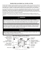
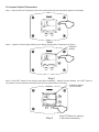
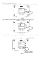
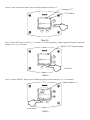
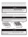
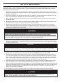
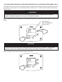
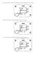
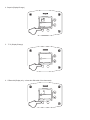
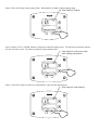
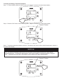
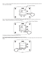
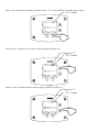
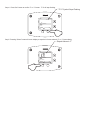
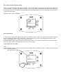
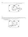
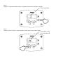
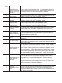
This manual must be kept with the appliance
February 2012
Part No E191 Addendum
CSC
Temperature Selection Procedure
Auto-Ignition Addendum
Natural Gas, Propane & Butane Fired
Storage Water Heaters
MODELS CSC39, CSC59, CSC78, CSC93, CSCL39, CSCL59, CSCL78, CSCL93
Auto Ignition
Working towards
a cleaner future
TEMPERATURE ADJUSTMENT (24V CONTROL SYSTEM)
The water heater temperature setting is adjusted by using the control display mounted to the front of the control panel of
the water heater. The water heater thermostat is set at the lowest setpoint of 70°F when shipped from the factory. The
control display shows the temperature setpoint in degrees Fahrenheit (°F) or degrees Celsius (°C), and the status of the
water heater (“Idle” or “Heating”). If the water heater is functioning normally, the display will also show “Operational”.
For energy efficient operation of your water heater, the suggested initial temperature setting is 120°F (49° C). During the
winter season, or any cold period, you may desire a higher temperature setting to adjust for the colder incoming water.
This adjustment, however, may cause additional condensation to form on the cooler tank surface. This does not mean
the tank is leaking. During summer months, the warmer incoming water temperatures will benefit the performance of your
water heater and reduce the amount of condensation developed.
Condensation does not mean your tank is leaking. Over 40% of reported tank leaks on installation are proven to be
condensation. To avoid unnecessary expense and inconvenience, make sure the tank is leaking before calling a service
person.
WARNING
If the water heater display does not show “Operational” in the “Status” indicator, there may be an operating
malfunction with the water heater. If this is the case, a numeric code will be displayed. Refer to the label next to the
display for the definition of the error code and call your plumbing professional or service agent to service the water
heater. Do not try to reset the water heater without having a qualified service person to diagnose and correct the
problem. If the display is blank or does not show an error code, make sure there is power to the water heater.
Setting the water temperature to the maximum set point can result in scalding hot water delivered to the faucets. It
is highly recommended that the maximum setpoint be adjusted to the lowest temperature possible for the needs of
the installation. See following section to change the maximum setpoint limit (max setpoint). Make sure the water
heater control display is not in a public area that can result in the temperature settings being improperly adjusted.
See previous warning on scalds and an ASSE approved mixing valve.
NOTICE
When the maximum setpoint is reached, the display will show “Max Setpoint” without the setpoint value. The
maximum setting is equal to approximately 180˚F (82˚C).
The default temperature setpoint from the factory is 70˚F (21˚C).
Shown flashing
in display only when
temp is adjusted
Sequence of
operation Indicator
Reads "Idle” or “Heating"
Status Indicator
Read "Operational"
or "Service Needed"
Select button
Water Heater Display and Control Buttons
Temperature
Up Button
°F
setpoint
idle
Status Operational
SELECT
SET
Temperature Setpoint
in Degrees F or Degrees C
Range 70 - Max °F
Range 21 - Max °C
Temperature
Down Button
Set button
To Increase Setpoint Temperature
Step 1: Depress and hold “Temperature Up” button until desired setpoint temperature appears in the display.
°F
idle
Status Operational
SELECT
SET
%
Step 1
Step 2: “Setpoint” indicator begins flashing in the display after pressing “Temperature Up” button.
"Setpoint"
flashes
°F
setpoint
idle
Status Operational
SELECT
SET
%
Step 2
Step 3: Press “SET” button for new setting to take effect immediately. “Setpoint” will stop flashing. If the “SET” button is
not pressed, the new temperature setting will take effect in approximately 10 seconds.
"Setpoint" flashes
for 10 seconds
°F
setpoint
idle
Status Operational
SELECT
%
Step 3
SET
Press SET Button for setting to
to take effect immediately
To Decrease Setpoint Temperature
Step 1: Depress and hold “Temperature Down” button until desired setpoint temperature appears in the display.
°F
idle
Status Operational
SELECT
SET
%
Step 1
Step 2: “Setpoint” indicator begins flashing in the display after pressing “Temperature Down” button.
"Setpoint"
flashes
°F
setpoint
idle
Status Operational
SELECT
SET
%
Step 2
Step 3: Press “SET” button for new setting to take effect immediately. The setpoint will stop flashing. If the “SET” button
is not pressed, the new temperature setting will take effect in approximately 10 seconds.
"Setpoint" flashes
for 10 seconds
°F
setpoint
idle
Status Operational
SELECT
%
SET
Press SET for setting to
take effect immediately
Step 3
To Change Temperature Format in Display from °F to °C or ˚C to ˚F:
Step 1: Press “SELECT” button until °F/°C is displayed.
°F
°F/°C
idle
Status Operational
&
SELECT
Press select
SET
Step 1
Step 2: Press “SET” button to change temperature format. Symbol °F/°C will flash.
°F
°F/°C
idle
Status Operational
SELECT
%
%
SET
°F/°C Flashes
Step 2
Step 3a: Press “Temperature Up” button to change temperature format to °C.
Changes to "°C"
°C
idle
Status Operational
SELECT
°F/°C
SET
°F/°C Flashes
Step 3a
Step 3b: Press “Temperature Down” button to change temperature format to °F.
Changes to "°F"
°F/°C Flashes
°F
°F/°C
idle
Status Operational
SELECT
SET
%
Step 3b
Step 4: Press “SET” button to confirm ˚F or ˚C format. °F/°C will stop flashing. Setpoint display will appear in the format
selected (˚F or ˚C) in 10 seconds.
Symbol "°F/°C" Stops Flashing
°F
°F/°C
idle
Status Operational
%
SELECT
SET
Press Set
Step 4
Step 5: Pressing “SELECT” button will return display to setpoint in format selected (˚F or ˚C) immediately.
Setpoint shown in °F
°F
idle
Status Operational
&
SELECT
SET
Press select
Step 5
An automatic gas shut-off device (ECO) is incorporated in the sensor and control board which will shut off all gas supply
to the burner and pilot if the water heater temperature exceeds 200°F (93°C). Should the ECO function (open), the water
temperature should be reduced to approximately 120°F (49°C) and follow applicable Lighting Instructions to place the
water heater in operation. The water heater must have the problem corrected by a qualified service person before putting
the water heater back in operation. It is recommended that all service work be performed by a qualified service agency.
If the water heater is to remain idle for 30 days or more or is subjected to freezing temperatures while shut off, the water
heater and piping should be fully drained (See “To Drain the Water Heater”) and the drain valve should be left fully open.
WARNING
Hydrogen gas can be produced in an operating water heater that has not had water drawn from the tank for
a long period of time (generally two weeks or more). Hydrogen gas is extremely flammable. To prevent the
possibility of injury under these conditions, we recommend the hot water faucet to be open for several
minutes at the kitchen sink before you use any electrical appliance which is connected to the hot water
system. If hydrogen is present, there will be an unusual sound such as air escaping through the pipes as
hot water begins to flow. Do not smoke or have open flame near the faucet at the time it is open.
Burner Flame Check
At the time of installation and at periodic intervals (about every 3 months), a visual check of the pilot and burner flames
should be made to determine if they are burning properly. No adjustment to the air shutter should be required for this
heater. The burner flames should be blue with yellow tips. A blue-orange flame is characteristic of operation on liquefied
petroleum (LP) gas. If the burner flame does not appear as described, an air shutter adjustment may be required. The
burner tube flames should light smoothly from the pilot.
NOTICE
IMPORTANT- In the event of an emergency, turn off the gas and electric (if applicable) to the appliance.
IMPORTANT- The water heater should be inspected at a minimum annually by a qualified service technician
for damaged components and/or joints not sealed. DO NOT operate this water heater if any part is found
damaged or if any joint is found not sealed
Figure 8
WARNING
Water heaters are heat producing appliances. To avoid damage or injury there shall be no materials stored against
the water heater or vent system, and proper care shall be taken to avoid unnecessary contact (especially by
children) with the water heater and vent system. UNDER NO CIRCUMSTANCES SHALL FLAMMABLE
MATERIALS, SUCH AS GASOLINE OR PAINT THINNER BE USED OR STORED IN THE VICINITY OF THIS
WATER HEATER, VENT SYSTEM OR IN ANY LOCATION FROM WHICH FUMES COULD REACH THE WATER
HEATER OR VENT SYSTEM.
SECTION X: MAINTENANCE
The following maintenance should be performed by a qualified service technician at the minimum periodic intervals
suggested below. In some installations, the maintenance interval may be more frequent depending on the amount of use
and the operating conditions of the water heater. Regular inspection and maintenance of the water heater will help to
insure safe and reliable operation.
1. Annual checks of the ignition systems (millivolt and electronic), temperature controls and any other water heater
controls are necessary to ensure proper operation. Also, all safety shut-off valves must be checked to verify proper
operation and tightness.
2. The flow of combustion and ventilation air MUST NOT be restricted. Clear the combustion air openings of any dirt,
dust, or other restrictions. WARNING! The combustion ventilation system may be HOT.
3. At all times keep the water heater area clear and free from combustible materials, gasoline and other flammable
vapors and liquids.
4. Bi-annually conduct a visual check of the pilot and burner flames to determine that they are burning properly. See
“Burner Flame Check” section for example of proper burner flame pattern.
5. Annually remove the main burner rack assembly to clean orifices and related parts of any dirt or other foreign
material. Inspect the burner ports for obstructions or debris and clean with a wire brush, vacuum, or use a mild
detergent solution to clean as needed. NOTE: It is imperative for proper operation of the water heater that the main
burner rack be replaced in the original location.
WARNING
When lifting lever of the combination temperature and pressure relief valve, hot water will be released under
pressure. Be careful that any released water does not result in bodily injury or property damage.
Keep clear of the combination temperature and pressure relief valve discharge line outlet. The discharge
may be hot enough to cause scald injury. The water is under pressure and may splash.
6. At least once a year, check the combination temperature and pressure relief valve to insure that the valve has not
become encrusted with lime. Lift the lever at the top of the valve several times until the valve seats properly without
leaking and operates freely.
NOTICE
IMPORTANT- If the combination temperature and pressure relief valve on the appliance discharges periodically, this
may be due to thermal expansion in a closed water supply system. Contact the water supplier or local plumbing
inspector on how to correct this situation. Do not plug the combination temperature and pressure relief valve outlet.
7. Monthly drain off a gallon of water to remove silt and sediment. WARNING! This water may be HOT.
8. All models are equipped with a cleanout opening to aid in removal of hard water deposits from the tank bottom. If
this water heater operates under hard water conditions, the following should be performed at least every 3 months:
Drain the water heater. Remove the cleanout jacket cover and tank cover. When cleaning the tank, care must be
taken to avoid trying to break deposits loose as this could damage the glass lining and shorten the life of the water
heater. After cleaning, replace the cleanout tank cover and jacket cover, and refill with water.
9. A sacrificial anode rod has been installed to extend tank life. The anode rod should be inspected annually (every
year) and replaced when necessary to prolong tank life. Water conditions in your area will influence the time
interval for inspection and replacement of the anode rod. Contact the plumbing professional who installed the water
heater or the manufacturer listed on the rating plate for anode replacement information. The use of a water softener
may increase the speed of anode consumption. More frequent inspection of the anode is needed when using
softened (or phosphate treated) water.
10. The venting system must be inspected at least once a year to ensure against leakage of exhaust products.
CAUTION
FOR YOUR SAFETY, DO NOT ATTEMPT REPAIR OF COMBINATION GAS CONTROL, BURNERS OR GAS
PIPING. REFER REPAIRS TO A QUALIFIED SERVICE TECHNICIAN.
ACCESSING SERVICE MODE ON THE WATER HEATER DISPLAY (FOR SERVICE PERSONNEL ONLY)
The display has a “service mode” for changing the maximum setpoint and accessing information in aiding servicing of the
water heater. This procedure is for service and installation personnel only. To enter the Service Mode, follow the steps
illustrated below:
WARNING
The following procedure is for service and installation personnel only. Resetting lockout conditions
without correcting the malfunction can result in a hazardous condition.
Step 1: Press “Select” and “Temperature Up” buttons together and hold for 3 seconds until “Max Setpoint” is shown in the
display.
"Max Setpoint"
next to Temperature
Setpoint value
Max
Setpoint
idle
Status Operational
&
SELECT
SET
%
NOTICE
30 Seconds after the last button press, the display will automatically return to the “User Mode”. Simultaneously
pressing the “Select” and “Temperature Up” buttons will switch the display immediately to the “User Mode”.
Step 2: Pressing “Select” button will change display to next mode
°F
Water
Temp
idle
Status Operational
&
SELECT
SET
The following is the sequence of modes available in “Service Mode” by pressing the “Select” button:
Error Code Number (Display/Reset). This is only shown if there is an operating error in the “User Mode”.
Error Code Shown
in Water Heater Display
Status
Service Needed
SELECT
Lockout RESET
1. Max Setpoint (Display/Change)
Max Setpoint value
Water Heater Display
°F
Max
Setpoint
idle
Status Operational
&
SELECT
SET
2a. Water Temperature Average (Displays average if there are two sensors – sensor temperature displayed if single
sensor is used).
°F Water Temp
idle
Status Operational
&
SELECT
SET
2b. Water Temperature - Upper Sensor (Displays if there is an upper sensor – some models)
°F
idle
Status Operational
Upper Sensor
&
SELECT
SET
2c. Water Temperature - Lower Sensor (Displays if there are two sensors)
°F
idle
Status Operational
&
Lower Sensor
SELECT
SET
3. Flame Current of Pilot Flame Sensor (Displays only in the Heating Cycle)
µA
Heating
Flame Current
Status Operational
&
SELECT
SET
4. Setpoint (Display/Change)
°F
setpoint
idle
Status Operational
&
SELECT
SET
5. ˚F/˚C (Display/Change)
°F
°F/C°
idle
Status Operational
&
SELECT
SET
6. Differential (Display only – shows the differential of the thermostat)
°F Differential
idle
Status Operational
&
SELECT
SET
7. Software Version (Display only)
Soft
idle
Status Operational
&
SELECT
SET
8. Error Code History (Displays if there are present error codes or up to 10 previous error codes). Water Heater Display
will show -- if there are no error codes.
No current error codes
idle
Status Operational
&
SELECT
SET
To change the Maximum Setpoint Limit (Max Setpoint) for the temperature setpoint:
WARNING
Setting the water temperature to the maximum set point can result in scalding hot water delivered to the taps. It
is highly recommended that the maximum setpoint be adjusted to the lowest temperature possible for the needs of
the installation. See following section to change the maximum setpoint limit (max setpoint). Make sure the water
heater control display is not in a public area that can result in the temperature settings being improperly adjusted.
See previous warning on scalds and an ASSE approved mixing valve.
Step 1: In service mode press the “Select” button until “Max Setpoint” is displayed.
°F
Max
Setpoint
idle
Status Operational
&
SELECT
SET
Step 2: Press “Set” button to enter setting mode. “Max Setpoint” will flash to indicate setting mode.
"Max Setpoint" Flashes
°F
Max
Setpoint
idle
Status Operational
%
SELECT
SET
Step 3: Press the “UP” or “DOWN” buttons to change the maximum setpoint value. This will limit the maximum setpoint
the user can select. Note: The maximum setpoint is approximately 180˚F.
"Max Setpoint" continues to flash
while making adjustments
°F
Max
Setpoint
idle
Status Operational
SELECT
SET
%
Step 4: Press “Set” button to confirm new “Max Setpoint” value and stop setting mode.
"Max Setpoint" stops flashing
°F
Max
Setpoint
idle
Status Operational
SELECT
%
SET
Step 5: 30 Seconds after the last button press, the Water Heater Display will go back to “User Mode”. It will read “Max
Setpoint” without showing a temperature value if the temperature setpoint is at the maximum setting. The Water Heater
Display can be set back to the “User Mode” immediately by pressing both the “Temperature Up” and “Select” buttons
together for 3 seconds.
Max
Setpoint
idle
Status Operational
&
SELECT
SET
%
Exiting Service Mode
Display of Water Temperature:
Step 1: In Service Mode, Press the “Select” button until “Water Temp” is displayed in the upper right section of the water
heater display. For water heaters using two temperature sensors in the tank, this will be the average reading between the
two sensors. For water heaters using a single sensor, this is the reading for the sensor.
°F
Water
Temp
idle
Status Operational
&
SELECT
SET
Step 2: For water heaters using two temperature sensors, pressing the “Select” button again displays the Upper Sensor
temperature reading. “Upper Sensor” will be displayed in the lower right side of the status window of the water heater
display.
°F
idle
Status Operational
Upper Sensor
&
SELECT
SET
Step 3: For water heaters using two temperature sensors, pressing the “Select” button again displays the Lower Sensor
temperature reading. “Lower Sensor” will be displayed in the lower left side of the status window of the water heater
display.
°F
idle
Status Operational
&
Lower Sensor
SELECT
SET
To Display Flame Sense Current of the Pilot Flame Sensor:
The pilot flame sense current is available only when the burners are in operation. Step 1: Make sure the status displays
“Heating” or draw enough hot water to start the burners. Step 2: Enter the “Service Mode” described previously. Step 3:
Press the “Select” button until a number value is displayed with “Flame Current” to the right of the number. The value
displayed is in microamps (µA).
Flame
Current
µA
Heating
Status Operational
&
SELECT
SET
To Display and Change Temperature Setpoint:
Step 1: In “Service Mode” press the “Select” button until “Setpoint” is shown in the water heater display.
°F
setpoint
idle
Status Operational
&
SELECT
SET
Step 2: Press the “Set” button to enter the setting mode. “Setpoint” will flash in the water heater display.
"Setpoint" Flashes
°F
setpoint
idle
Status Operational
%
SELECT
SET
Step 3: To raise the temperature setpoint, press the “Temperature Up” button until the desired temperature is shown on
the water heater display.
NOTICE
Note: The maximum temperature that can be set in the Water Heater Display is limited to the “Max Setpoint”
described previously. To change the “Max Setpoint”, refer to the procedure “To Change the Maximum Setpoint
Limit…” described previously under “Accessing the Service Mode on the Water Heater Display”.
"Setpoint" Flashes
°F
setpoint
idle
Status Operational
SELECT
SET
%
Step 4: To lower the temperature setpoint, press the “Temperature Down” button until the desired temperature is shown
on the water heater display.
"Setpoint" Flashes
°F
setpoint
idle
Status Operational
SELECT
SET
%
Step 5: When the desired setpoint is reached on the water heater display, press the “Set” button to confirm the new
setpoint. “Setpoint” stops flashing in the water heater display.
"Setpoint" Stops Flashing
°F
setpoint
idle
Status Operational
%
SELECT
SET
To Display and Change Temperature Format (˚F/˚C):
To Change Temperature Format in Display from ˚F to ˚C or ˚C to ˚F:
Step 1: While in “Service Mode”, press “Select” button until “˚F/˚C” is shown in the upper right portion of the water heater
display.
°F
°F/C°
idle
Status Operational
&
SELECT
SET
Step 2: Press “Set” button to change temperature format. “˚F/˚C” symbol will flash in the water heater display.
"°F/°C" Flashes
°F
°F/C°
idle
Status Operational
%
SELECT
SET
Step 3a: Press “Temperature Up” button to change temperature format to ˚C.
Changes to "°C"
"°F/°C" Flashes
°C °F/C°
idle
Status Operational
SELECT
SET
%
Step 3b: Press “Temperature Down” button to change temperature format to ˚F.
Changes to "°F"
"°F/°C" Flashes
°F
°F/C°
idle
Status Operational
SELECT
SET
%
Step 4: Press “Set” button to confirm ˚F or ˚C format. ˚F/˚C will stop flashing.
"°F/°C" Symbol Stops Flashing
°F
°F/C°
idle
Status Operational
%
SELECT
SET
Step 5: Pressing “Select” button will return display to setpoint in format selected (˚F or ˚C) immediately.
Setpoint shown in °F
°F
idle
Status Operational
&
Lower Sensor
SELECT
SET
How to reset the control from Lockout Conditions:
WARNING
The following procedure is for service and installation personnel only. Resetting lockout conditions without
correcting the malfunction can result in a hazardous condition.
If an error code is displayed (except for #4, low flame sense current), the water heater will be in a “lockout condition” with
the water heater display showing the error code number and “Service Needed” in the status section of the display
window. Error codes 62 (maximum number of retries detected) and 63 (maximum number if ignition recycles detected)
are “Soft Lockouts” in which the control can be reset in the “User Mode” by pressing the lower right button under “Lockout
Reset” shown in the lower right portion of the display. The control will also go through 3 attempts to relight the burners
every hour in the soft lockout condition.
Resetting Error Codes in Soft Lockout Condition
Error Code Shown in
Water Heater Display
Status
Service needed
SELECT
%
Lockout RESET
Press for 2 seconds
All other error codes will put the water heater into a “Hard Lockout” condition, in which the water heater will not operate
and cannot be reset in the “User Mode”. To reset a hard lockout, first enter the “Service Mode” described earlier by
pressing both the “Temperature Up” and “Select Buttons” at the same time for 3 seconds. Then press the lower right
button under “Lockout Reset” in the water heater display and hold for 3 seconds.
Resetting Error Codes in Hard Lockout Condition
Error Code Shown in
Water Heater Display
Status Service Needed
&
SELECT
SET
%
Step 1: Press for 3 seconds
to enter service mode.
Status Service Needed
SELECT
Lockout RESET
Step 2: Press for 3 seconds to
reset control in service mode.
Error Codes and Error History Display:
If there is an operating problem with the water heater, an error code number will appear on the water heater display with
“Service Needed” to the right of the “Status” indicator. The error code label is located below the water heater display and
the following section in this Installation and Operating Instruction Manual explains the error codes with corrective actions
to repair the water heater.
Example of Error Code in the Display:
idle
Service Needed
SELECT
SET
Error Code History:
In “Service Mode” pressing the “Select” button after the “Software Version” (item 8 in the previously described sequence
of service modes) will show an error code history, if there have been any previous operating problems with the water
heater. If the display shows --, there is not a current error code.
The Water Heater Display will provide up to 10 previous error codes. The oldest error code will be stored in code index
#1 and the most recent in code index #10 (if there are 10 error codes).
To view previous error codes:
Step 1:
In “Service Mode” press the “Select” button until the next display after the “Software Version”. If there are no current error
codes, the display will show -- .
No Current Error Code
°F
idle
Status Operational
&
SELECT
SET
Step 2:
Press the “Temperature Down” button to select the error code index, starting with the most recent error code “10”.
Error Code Index
idle
Status Operational
SELECT
SET
%
Step 3:
Press the “Select” button to view the error code for “code 10”. If there is a number displayed, note what the number is.
The label next to the water heater display will identify the code number. If no number is displayed with only a “--“ in the
water heater display, then there has not been an error code for error code index 10.
No Error Code Shown
for Code Index 10
idle
Status Operational
&
SELECT
SET
Step 4:
Press the “Temperature Down” button to change to the previous code index, code #9.
Error Code Index
idle
Status Operational
SELECT
SET
%
Step 5:
Press the “Select” button for code index #9 to view if there are any code numbers.
Stored Error Code
For Code Index #9
idle
Status Operational
&
SELECT
SET
Step 6:
Continue pressing the “Temperature Down” button to change to the next error code index and press “Select” to view the
error code number, if any, for that index number. Continue on to index #1, the oldest error code index. The water heater
display will store up to 10 error codes with the oldest code starting in code index #1 with the most recent code in code
index #10.
Step 7: 10 seconds after the last button press, the Water Heater Display will revert back to the current error code display.
To exit Service Mode, either wait 30 seconds or press Temperature Up button and Select Button for 3 seconds.
°F
setpoint
idle
Status Operational
&
SELECT
SET
%
Exiting Service Mode
DIAGNOSTIC ERROR CODES AND TROUBLESHOOTING PROCEDURES FOR HONEYWELL INTEGRATED
CONTROLS (24 VOLT FLUE DAMPER MODEL SERIES)
Error
Code
Definition of Code
4
Low Flame Sense
Current
55
Damper End Switch
Failed to Close
(Stuck Open)
56
Damper End Switch
Failed to Open (Stuck
Closed)
Cause of Problem and Actions Taken to Correct
Determine flame sense current in the Service Mode with the water heater
operating. If less than 1.0 microamps, check pilot flame sense rod and wire.
Clean flame sense rod with emery cloth. If problem is not solved, replace
pilot.
Check to see if flue damper has fully opened. If not, disconnect damper
harness at damper plug connection and check for 24 volts between pins on
red and white wires. If no voltage, check wire harness or measure output on
control board (pins 1&4). If there is no voltage at the control board, replace
control. Replace wire harness if voltage does not pass to the pin terminals
from the control. If there is 24 volts at flue damper connection, replace flue
damper. If damper is open, disconnect harness and check continuity
between pins from black and yellow wires on flue damper. If no continuity,
replace flue damper.
Check to see if flue damper has fully closed. If not, disconnect damper
harness at damper plug connection and check for 24 volts between pins on
red and white wires. If no voltage, check wire harness or measure voltage
output on control board (pins 1&4). If there is no voltage at the control
board, replace control. Replace wire harness if voltage does not pass to the
pin terminals from the control. If there is 24 volts at flue damper connection,
replace flue damper. If damper is closed, disconnect harness and check
continuity between pins from black and yellow wires on flue damper. If there
is continuity, the end switch is stuck closed. Replace flue damper.
Error
Code
Definition of Code
Cause of Problem and Actions Taken to Correct
6
Flame Sensed Out of
Normal Sequence
(Before Opening Gas
Valve or After Closing
Gas Valve)
Check to make sure gas valve has closed. No voltage should be present at
the gas valve before or after ignition cycle. Make sure wire positions on the
wire harness are correct. If gas valve is stuck open, replace.
23
Flame Detected
Before Ignition
24
31
32
Flame Detected After
Heating Cycle
Completes
Upper Sensor
Readings Faulty
Lower Sensor
Readings Faulty
57
Flame Rod Shorted
to Ground
58
AC Line Frequency
Error – Signal Too
Noisy or Frequency
Incorrect
59
Line Voltage Too Low
or High
61
DC Output Voltage
Unstable
62
Maximum Number of
Retries Detected
63
Maximum Number of
Ignition Recycles
Detected
64
Electronics Failure
65
High Water
Temperature (Over
200˚F)
Check to make sure gas valve has closed. No voltage should be present at
the gas valve before the ignition cycle. Make sure wire positions on the wire
harness are correct. If gas valve is stuck open, replace.
Check to make sure gas valve has closed. No voltage should be present at
the gas valve before the ignition cycle. Make sure wire positions on the wire
harness are correct. If gas valve is stuck open, replace.
Resistance of upper sensor out of operating range. Check continuity of wire
harness to upper sensor, and if O.K., replace upper sensor.
Resistance of lower sensor out of operating range. Check continuity of wire
harness to lower sensor, and if O.K., replace lower sensor.
Pilot flame sensor rod is shorted to ground. Check to see if flame sensor
wire has bare spots touching metal parts of if flame sensor rod is touching
the pilot shield or other metal parts. Replace pilot if flame sense wire is
damaged or flame rod is bent.
Check line voltage frequency to the water heater. Determine if there are
wide fluctuations. Call an electrician if the problem persists. The water
heater should be on a separate line.
Check line voltage to the water heater. Determine cause of low or high
voltage. Call an electrician or your utility. The water heater should be on a
separate line.
Check line voltage to the water heater for erratic readings. Also check
wiring to make sure there are no shorts. If power supply and wiring is O.K.,
replace control board.
Pilot is either not lighting or not staying lit during the ignition cycle. Check
inlet gas pressure for minimum pressure on rating label. Is pilot electrode
sparking? Check gas valve wire harness for broken wires or shorts. If 24
volts is present between PV and PV/MV terminals at the gas valve, replace
gas valve. Check for voltage output to the yellow and red gas valve wires on
the control board pins. If during the ignition trial period, there is no voltage
present at the control board pin terminal for the red and yellow wires leading
to the gas valve, then replace the control board. Replace pilot if wires are
damaged or electrode is damaged.
Pilot flame is lost during run cycle, then reestablished on ignition cycle.
Check inlet gas pressure. Is gas pressure dropping below the minimum
operating pressure on the rating label after the main gas valve opens? Is
the gas pipe size to the water heater adequate? Check the pilot shield
position and condition of the burners. Clean or replace as needed. Check
the pilot flame and observe the microamp output on the run cycle. Check
the pilot tubing to the pilot and replace if crimped or damaged. Replace pilot
if wires, flame sensor, or electrode is damaged.
Replace control board.
Water temperature in tank has exceeded 200˚F. Check lower sensor. Make
sure sensor is fully inserted into the well (clip on sensor wire secures sensor
in place). Check lower and upper (where used) sensor readings. If not
within specifications, replace sensor. If sensor and wire harnesses check
O.K., replace control board.
Procedure for Checking Thermostat Sensors
Set the thermostat above water temperature (See temperature adjustment section) and observe system through one (1)
complete cycle. Make sure system operates as desired.
To check the upper sensor or lower sensor assembly, compare the resistance of the sensor terminals (blue leads for
upper sensor, yellow and black lead for lower sensor) as measured by an ohmmeter to the water temperature as
measured by an accurate thermometer. Thermistor resistance increases as the temperature decreases. The tables
below show the correct sensor resistance at various temperatures. Replace the sensor if the ohm reading in the chart
does not approximate the reading from the sensor at the temperature measured in the tank.
°F
0
1
40
26109
25400
60
15314
14925
50
70
80
90
100
110
120
130
140
150
160
170
19906
11884
9299
7333
5827
4663
3758
3048
2488
2043
1688
1402
19383
11592
9078
7165
5697
4562
3679
2986
2439
2004
1656
1376
2
3
In Degrees F
24712
24045
14548
14180
18876
11308
8862
7000
5570
4464
3602
2925
2391
1966
1625
1351
18383
11032
8653
6839
5446
4368
3527
2866
2344
1928
1595
1327
4
5
6
23399
22771
22163
13823
13477
13140
17905
10763
8449
6683
5326
4274
3453
2808
2298
1891
1566
1303
17440
10502
8250
6531
5208
4183
3382
2752
2253
1856
1567
1280
16990
10248
8057
6383
5094
4094
3312
3697
2209
1820
1509
1257
7
8
9
21573
21000
20445
12812
12494
12185
16553
10000
7869
6238
4982
4006
3244
3643
2166
1786
1481
1235
16128
9760
7685
6098
4873
3922
3177
2590
2124
1753
1454
15715
9526
7507
5961
4767
3839
3112
2538
2083
1720
1427
1213
1191
857
842
180
1170
1150
1129
1110
1090
1071
1053
1035
1017
200
828
814
801
788
775
762
749
737
725
713
°C
0
10
20
30
40
50
60
70
80
90
0
32648
19898
12492
8057
5327
3602
2488
1752
1256
916
1
31026
18968
11942
7722
5117
3468
2400
1693
1216
888
2
29495
18088
11419
7403
4917
3340
2316
1637
1177
861
6
24166
14998
9572
6268
4201
2878
2011
1432
1037
763
7
23010
14322
9165
6016
4042
2774
1942
1385
1005
741
8
21915
13680
8778
5775
3889
2675
1876
1340
974
719
9
20879
13071
8409
5546
3742
2579
1813
1297
944
698
190
982
965
949
933
917
901
In Degrees C
3
4
5
28049 26682 25389
17253 16461 15710
10922 10450 10000
7099
6808
8532
4726
4543
4368
3217
3099
2986
2235
2157
2083
1582
1530
1480
1140
1105
1070
835
810
786
886
871
999
Publication Date: 0212
0087
Baxi Commercial Division
Wood Lane, Erdington,
Birmingham B24 9QP
Sales:
Technical:
0845 070 1056 0845 070 1057
Email: [email protected]
www.andrewswaterheaters.co.uk