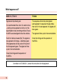
1
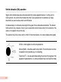
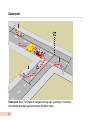
An Introduction to
the Use of Portable
Vehicular Signals
March 2008
7611 Introduction to the Use of Portable Vehicular Signals v4_2.indd 1
1
27/11/2013 14:56
This booklet is for people with specific responsibility for portable vehicular signals at street works
and road works. Sites with alternate one-way vehicular flows are referred to as ‘shuttle’ working.
For current information about traffic control at street works and road works, including health and
safety issues, you, or your supervisor, should refer to Chapter 8 of the Traffic Signs Manual and to
Safety at Street Works and Road Works: A Code of Practice.* For convenience, in this booklet these
will be referred to as ‘Chapter 8’ and ‘the Code of Practice’ respectively.
*Text in blue ink shows matters that may need to be referred to your supervisor.
An Introduction to
the Use of Portable
Vehicular Signals
London: TSO
7611 Introduction to the Use of Portable Vehicular Signals v4_2.indd 3
27/11/2013 14:56
Department for Transport
Great Minster House
33 Horseferry Road
London SW1P 4DR
Web site www.gov.uk/dft
© Queen’s Printer and Controller of Her Majesty’s Stationery Office, 2008, except where otherwise stated.
Copyright in the typographical arrangement rests with the Crown.
You may re-use this information (not including logos or third-party material) free of charge in any format or medium, under the
terms of the Open Government Licence. To view this licence, visit www.nationalarchives.gov.uk/doc/open-government-licence/ or
write to the Information Policy Team, The National Archives, Kew, London TW9 4DU, or e-mail: [email protected].
ISBN 978 0 11 552936 8
Ninth Impression 2013
Printed in Great Britain on paper containing at least 75% recycled fibre.
7611 Introduction to the Use of Portable Vehicular Signals v4_2.indd 4
27/11/2013 14:56
Introduction
This booklet does not cover portable pedestrian crossing facilities. See Traffic Advisory Leaflet 3/11:
Signal-controlled pedestrian facilities at portable signals for advice on the use of these facilities.
The leaflet is available from the Department’s website at
www.gov.uk/government/publications/signal-controlled-pedestrian-facilities-at-portable-traffic-signals
You, or your supervisor, will need to discuss the placing of portable traffic signals with the traffic
authority. Permission in writing will be required, and express approval to the placing of the signals at
a particular site may be needed. If the permission/express approval gives positions for signal heads
etc., it is important that the layout follows those instructions. Lack of permission/approval and/or
incorrect layout may make the site unlawful. You, or your supervisor, should check if in doubt.
If the works are close to or are likely to affect level crossings, permanent signal-controlled junctions
and controlled crossings (including Zebras), the traffic authority must be involved before you proceed.
In the case of level crossings, the railway authority must also be involved at an early stage.
1
7611 Introduction to the Use of Portable Vehicular Signals v4_2.indd 1
27/11/2013 14:56
The system
Signal heads: the Code of Practice says that consideration should be given to providing two signal
heads on each approach. However, whether one or two signal heads are used, for safe operation, the
approaching driver must be able to see at least one signal on the approach and one whilst waiting at
the WAIT HERE sign (see ‘Setting up the equipment’). Signal heads must be either: compliant to the
European Specification EN 12368, or of a type approved to TR 2206, or the TR 0102 amendment to
BS 505. The information may be on the signal head, otherwise check with the supplier.
Portable signal controllers are linked to the signal heads and detectors by either:
• cables: which will need protecting where they cross the carriageway, and are vulnerable to
problems from turning or accelerating/braking vehicles (see page 13), or
• radio control: care needs to be taken to ensure that other sources of radio transmission and
obstructions do not interfere with the radio link.
Energy sources include: diesel or Liquefied Petroleum Gas (LPG) generator, battery or mains electrical
supply through a suitable transformer.
The above factors, taking into account any environmental considerations, may influence your choice
of system. You, or your supervisor, should check with the manufacturer if in any doubt about the
above details.
2
What to do first
The portable signal controller and detector equipment must be of a type approved on behalf of the
Secretary of State for Transport. Specifications are issued by the Highways Agency.
Look on the controller for a label* for the specification reference. Most equipment will be approved
against MCE 0111, TR 0111, or the current TR 2502. Equipment to MCE 0111 and TR 0111 has the
same initial set-up (see pages 15 and 16), whereas that to TR 2502 is different. This booklet gives advice
on both initial set-up sequences. For ease of reference, the sequence of MCE 0111 and TR 0111 will
be highlighted in pink and that of TR 2502 in yellow. In addition, there is one controller approved to an
interim specification 027-008-024. References to 027-008-024 have been made separately.
Look on the detector housing for a label* stating which specification
applies. Equipment is approved against MCE 0114 (C), TR 2147, or
the current TR 2504. The detector housing may be fixed to the top
of the signal head; others are fitted below the head.
If the relevant controller/detection specification information is
not on a label, it may be on information in the controller housing.
However, if the specification information is not available, you
or your supervisor should check with the traffic authority that it
is approved.
*Note: There is no longer a requirement for the label to bear a crown emblem.
3
Vehicle Actuation (VA) operation
Signal control should always be vehicle actuated (VA) unless agreed otherwise, in writing, by the
traffic authority. You will find that modes other than VA are provided on the controller, but these
should only be used to relieve short-term difficulties.
VA reduces delay to vehicles by ensuring that the green time is adjusted automatically. The relevant
traffic authority may, however, instruct you to use another control mode, either for the duration of the
works, or for specific times of the day.
The selection may be by rotary switch, similar to that shown below, or by menu display and keypad.
All Red – holds signals on red to all approaches.
Manual (MAN) – should be used to stop traffic if the shuttle lane has to be
occupied for short periods (e.g. for unloading).
Fixed time (FT) – may be used while awaiting the arrival of the engineer if the
equipment needs attention. On some controllers there is no fixed time mode.
4
Vehicle Actuation (VA)
On VA, if there are no approaching vehicles, the signals will revert to red in both directions. The
first vehicle to arrive will register a demand for the signals to change on that approach. See ‘Nudge
circuit’ on page 14.
Following vehicles will extend the time that the green light is shown. The duration of the green will
vary between the minimum green period (7 or 12 seconds) and the maximum green period (settable
on the controller). The signals will change either when the last vehicle has passed, or after the
maximum time the green signal has been set for.
How does it work?
Each signal is provided with a vehicle-detector unit. These units normally use microwave technology
and are often referred to as an ‘MVD’ (Microwave Vehicle Detector). Other technology can be used,
but the unit must be approved (see page 3).
The MVD can detect most moving motor vehicles, including larger motorcycles, up to 40 metres
away, but with smaller motorcycles and cycles the distance is 25 metres — provided they are
travelling towards the MVD at speeds greater than 10 mph and the detector is correctly aligned (see
next page). Some detectors may be able to work outside these limits.
An indicator is illuminated when a vehicle is detected and the ‘detect’ message is sent from the MVD
to the controller.
5
What you need to do
Use only equipment of a type approved (a legal requirement) – see page 3.
All equipment on site can have problems, particularly from accidental and vandal damage. Maintenance contact information is therefore essential and should be readily available – for example, prominently displayed on the equipment. Test the equipment before setting up – see pages 14 to 16.
Set up the signing and equipment correctly – see pages 11 to 16.
Use the ‘VA’ setting on the controller.
Align the MVDs carefully at each end of the site – see page 14. Remember, MVDs cannot see around corners, parked vehicles, plant or materials! Neither can they work properly if they are: pointing at
the sky – or over a hedge, not facing oncoming traffic, or damaged by being roughly treated, for
example thrown onto the back of a lorry.
Use the correct All-Red and Maximum Green settings (see pages 7 to 10).
If there is a photocell fitted, ensure it is not going to be overshadowed by, say, a tree canopy. 6
Adjusting the timers
Look at the selection switches, or menu display/keypad, for the All-Red and Maximum Green timers
for each approach. This should make it clear whether to measure the distance between:
• the two ‘WAIT HERE’ signs – at sites with more than two approaches, the longest distance to the
other ‘WAIT HERE’ signs is used for that approach – or
• the ‘WAIT HERE’ sign and the ‘datum’ point. The datum point can be half way along the shuttle
working length, or a point in the centre of the junction (see page 8).
It is important to watch the vehicular flow at intervals and adjust the controller settings if necessary.
As the flow changes during the day and day-to-day, it is necessary to carry out this check several
times daily.
The following tables cover distances up to 300 metres between ‘WAIT HERE’ signs. If the longest
distance is above 300 metres, ask for advice from the relevant traffic authority before proceeding.
NOTE: Some authorities will need to be informed if the distance is over 200 metres. You, or your
supervisor, should check if in doubt.
7
Datum point
Datum point (Note: The Chapter 8 triangular warning signs, guarding on the footway
and possible secondary signals have been omitted for clarity.)
8
Adjusting the red timers
Measure the distance between ‘WAIT HERE’ signs, or the ‘WAIT HERE’ sign and datum point,
(see page 7), and use the table below:
Distance (metres)
All-Red time (seconds)
0
50
5
100
10
150
15
200
20
250
25
300
30
NOTE: On some controllers the All-Red switch may be marked in metres and the equipment converts to
seconds automatically.
Method of selection
and values may differ
If the site is on a steep gradient, you may need to increase the indicated
All-Red value for the uphill direction incrementally until vehicles clear safely.
If there are large numbers of slow-moving vehicles that have difficulty in
clearing the works before the lights have changed, increase indicated values
of the relevant All-Red settings incrementally until vehicles clear safely.
9
Adjusting the Maximum Green settings
Measure the distance between ‘WAIT HERE’ signs, or the ‘WAIT HERE’ sign and datum point,
(see page 7), and use the table below:
Distance (metres)
Green time (seconds)
30
75
35
135
40
195
45
300
50
NOTE: On some controllers the Maximum Green switch may be marked in metres, and the equipment
converts to seconds automatically.
Method of selection
and values may differ
0
Set the Maximum Green times to the appropriate settings.
15
20
60
25
30
50
35
45
40
MAXIMUM GREEN
(SECONDS)
10
If substantial queues begin to form and vehicles take more than one
green period to get through the site, then adjust the setting incrementally.
For each new setting allow a few green periods to assess the difference.
It is normal to increase the setting but, if this increases the queue, reduce
the setting, again allowing time to assess the result.
Setting up – general signing
Check that full Chapter 8 signing is provided and checked regularly. Log any problems and remedial
action taken. Make sure you are familiar with recommendations on the stability of signs and the need
for standby ‘STOP’/‘GO’ signs.
If possible, avoid placing signs and/or signals on the footway.
For additional advice on signing, including that for works on or near footways, see Chapter 8 and the
Code of Practice.
Care should be taken to allow sufficient room for vehicles to pass between the end of the works and
vehicles waiting at the signal. If the signal head is not within the coned-off area, protect it with traffic
cones. See the Code of Practice for detail on lead-in and exit tapers.
11
Setting up – ‘WAIT HERE’ signs
Position the signals where needed. For clear visibility of the signal and reliable
detector operation, there must not be any obstructions between the signals and
vehicles up to 70 metres away.
‘WAIT HERE’1 signs should be placed before the signal head. If there is a side
road controlled by portable signals use the ‘3-WAY CONTROL’2 sign.
If there are uncontrolled side roads joining works under signal controlled shuttle
working, use the two signs3,4 in addition to the ‘WAIT HERE’ signs.
1
12
2
3
4
Also variant –
‘4-WAY CONTROL’
In side road
On approach
to signals
Setting up – ‘RAMP’ signs
Many portable signals are radio controlled, but some are connected by cable. If the signals are on the near side of the road, cables may have to cross the shuttle lane. Cables crossing a road, should not be placed where vehicles are turning, or accelerating/ decelerating.
Where vehicles have to pass over the cable, use a cable crossing protector. These are designed to prevent damage to the cable and to allow vehicles, particularly those with two wheels, to cross safely.
‘RAMP’ and ‘RAMP AHEAD’ signs must be used, and it may be necessary to weight the cable crossing protector at each end to prevent lifting or twisting.
It should not be necessary for cables to cross the footway. 13
Setting up the MVDs
The MVDs work best if they are mounted on signals on the near side of the road.
A vehicle approaching the MVD, within the range given on page 5, should be detected. The indicator
will be illuminated on the MVD (see page 5). If this does not happen, check the alignment and readjust
as necessary. If the indicator still does not illuminate when the next vehicle approaches, call out the
service engineer.
If the indicator stays on regardless of approaching vehicles, the MVD probably needs replacing – call
the service engineer.
Specifications MCE 0114(C), TR 2147 and TR 2504 require that, if a detector has not registered a
demand for 2.5 minutes, the detector generates a demand via its ‘nudge circuit’. This will mean that
at quiet times the signals will change at least every two and a half minutes.
14
Initial set-up of the equipment
MCE 0111, TR 0111 TR 2502
1
Point signals away from the road so they
cannot be seen by drivers.
Align the signals and MVDs – see pages 5, 6,
12 to 14.
2
Connect the signal heads and power supply
to the controller.
Connect the signal heads and power
supply to the controller.
3
Set the controller to ‘MANUAL’.
Set the ‘All-Red’ controls – see pages 7 to 9.
4
Set the ‘All-Red’ controls – see pages 7 to 9.
Set the ‘Maximum Green’ controls – see
pages 7, 8 and 10.
5
Set the ‘Maximum Green’ controls – see
pages 7, 8 and 10.
Set the controller to Vehicle Actuated (VA).
6
Switch on signal heads and go to page 16.
Switch on signal heads. On some controllers
this may be achieved by selecting VA. Go to
page 16.
Controllers to 027-008-024 – consult the instructions for the equipment.
15
What happens next?
MCE 0111, TR 0111
TR 2502
Signals start by showing red.
The sequence will start by closing down
each approach in sequence through amber,
then red. On the last approach, the signals will
show green.
It is recommended that, when it is safe to do so
– working on one approach at a time, turn the
signal heads to face oncoming vehicles. Ensure
the MVDs are also aligned to face the vehicles.
Switch to Vehicle Actuated (VA). The signals to
one approach will change – red/amber, green.
Other approaches will stay red until the end of
the first approach green. The signals will then
cycle in the normal fashion.
The signals will then cycle in the normal fashion.
Check the timings and the operation of
the MVDs.
Check the timings and the operation of
the MVDs.
Controllers to 027-008-024 – consult the instructions for the equipment.
16
Trouble-shooting guide
Problem
Possible cause
Remedy
Very long vehicular queues
Maximum Green setting needs
adjusting
See page 10
Faulty detector (MVD)
Call service engineer*
Too many vehicles
Discuss with relevant
traffic authority urgently
Maximum Green setting needs
adjusting
See page 10
Faulty detector (MVD)
Call service engineer*
Low vehicular density
No action required
Vehicles entering shuttle lane
after start of red
If frequent, report facts to
the police
All-Red too short
Increase setting
Obstruction in carriageway
Clear obstruction
Green period always same length
Vehicles still in shuttle lane
at start of next green
* The signals may need to be controlled by using MANUAL or FIXED TIME, depending on the
severity of the problem.
17
Trouble-shooting guide (continued)
Problem
Possible cause
Remedy
Long gap between last
vehicle clearing shuttle lane
and start of next green
All-Red setting too long
Decrease setting
Signals do not remain on
red in absence of vehicles
Signals do not change
after one stream has
stopped, even though
vehicles are waiting
* See page 14 for nudge circuit.
Printed in the United Kingdom for TSO
J002593116 C15 04/12
18
Detector fault – working fixed time Call service engineer
Detector fault – working fixed time Call service engineer
Switched to Fixed Time
Switch to VA
Misaligned detectors
Re-align detectors
*’Nudge circuit’ operating
No action
Faulty detector (MVD)
Call service engineer, work
signals MANUALLY or FT until
engineer arrives.
All enquiries about this publication should be sent in writing to:
Department for Transport
Great Minster House
33 Horseferry Road
London SW1P 4DR
Published by TSO (The Stationery Office) and available from:
Online
www.tsoshop.co.uk
Mail, Telephone, Fax & E-mail
TSO
PO Box 29, Norwich, NR3 1GN
Telephone orders/General enquiries: 0870 600 5522
Fax orders: 0870 600 5533
E-mail: [email protected]
Textphone 0870 240 3701
TSO@Blackwell and other Accredited Agents