1
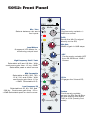
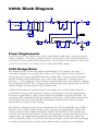
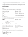
5052
Mic Pre / Inductor EQ
Serial #:
Operations Manual
5052 Mic Pre / Inductor EQ
Thank you for your purchase of the 5052 Mic Pre / Inductor EQ. Everyone at
Rupert Neve Designs hopes you enjoy using this tool as much as we have enjoyed
designing and building it. Please take note of the following list of safety concerns
and power requirements before the use of this product.
Safety
It’s usual to provide a list of “do’s and don’ts” under this heading but mostly these
amount to common sense issues. However here are some reminders:
Don’t operate your 5052 module in or around water! Electronic equipment and
liquids are not good friends. If any liquid is spilled such as soda, coffee, alcoholic
or other drink, the sugars and acids will have a very detrimental effect. Sugar
crystals act like little rectifiers and can produce noise (crackles, etc.). SWITCH OFF
IMMEDIATELY because once current starts to flow, the mixture hardens, can get
very hot (burnt toffee!) and cause permanent and costly damage. Please contact
support as soon as possible at [email protected] for resolution.
Safety Instructions:
1) Read these instructions.
2) Keep these instructions.
3) Heed all warnings.
4) Follow all instructions.
5) Do not use this apparatus near water.
6) Clean only with dry cloth.
7) Do not block any ventilation openings. Install in accordance with the
manufacturer’s instructions.
8) Do not install near any heat source such as radiators, heat registers, stoves, or
other apparatus (including amplifiers) that produce heat.
9) Do not defeat the safety purpose of the polarized or grounding-type plug. A
polarized plug has two blades with one wider than the other. A grounding type plug
has two blades and a third grounding prong. The wide blade or the third prong are
provided for your safety. If the provided plug does not fit into your outlet, consult
an electrician for replacement of the obsolete outlet.
10) Protect the power cord from being walked on or pinched, particularly at plugs
convenience receptacles and the point where they exit from the apparatus.
11) Only use attachments/accessories specified by the manufacturer.
12) Unplug this apparatus during lightning storms or when unused for long periods
of time.
13) Refer all servicing to qualified service personnel. Servicing is required when the
apparatus has been damaged in any way, such as when power-supply cord or plug
is damaged, liquid has been spilled or objects have fallen into the apparatus, the
apparatus has been exposed to rain or moisture, does not operate normally, or has
been dropped.
14) Do not expose this apparatus to rain or moisture.
15) The apparatus shall be connected to a mains socket outlet with a protective
earthing connection.
5052: Front Panel
5052
Mic Pre/EQ
Mic Pre
Mic / Line
Selects between mic and
line inputs
Trim
Continuously variable +/6dB trim control
0dB
MIC
LINE
5051 EQ/Compressor
INDUCTOR EQ
48V
0
-6
TRIM
+6
LINE 1
LINE 2
TO EQ
36
-15 HF +15 30
22
Level Meters
8 segment LED Meter for
monitoring output level
14
10
6
0
4
Mid Parametric
Selectable at 200, 350, 700,
1.5 K, 3 K, and 6 KHz. With
continuous gain from -15 to
+15dB. Selectable Hi Q.
MID HI Q
EQ PRE
POST
220
10020Hz
LO PEAK
250Hz
FREQ
60
35
8K
16K
1
3K 6K
-15 HF +15 1.5K 2
4
700
6
HF -15 LF +15
10
PEAK
350
14
0
200 18
0
MID FREQ
22
-6dB
GAIN
GR
+20
MID +15
2.5 S
LOW FREQ
75mS
ATTACK
LINK
LF
PEAK
3:1
1.5:1
LF +15
1.1:1
SILK
-10
40:1
RATIO
+10
RED / BLUE
COMP IN
MIN
-30dB
+20dB
THRESH
EQ In
Engages the 3-band EQ
RELEASE
35
5mS
-15
1S
100mS
60
50
25
MID
HI Q
220
100
EQ IN
22
20
18
14
10
4
-2
-10
Level
250
S/C
-15HPF
FF
FB
HPF
Continuously variable HPF
from 20-250Hz at 12dB /
Octave
LOW FREQ
0
0
Low Frequency EQ
Selectable at 35, 60, 100, and
220 Hz. Continuous gain from -15 to
+15dB Selectable peak or shelf curves.
MID FREQ
66
-15 MID +15
0
Mic Gain
66dB of gain in 6dB steps
0dB
100
HPF
High Frequency Shelf / Peak
60
-10
Red 120Hz
Blue 60Hz
Selectable at 8 and 16 Khz. With
continuous gain from -15 to +15dB.
Selectable peak or shelf curves
54
200
To EQ
Sends the Mic Pre signal
directly to the EQ
48
MIC GAIN
-2
HPF
6K
350
12
HI PEAK
42
700
18
18
3K
1.5K
24
8K
20
16K
EQ IN
MAX
TEXTURE
ICnductor
EQ
OMPRESSOR
Texture
Continuously variable
control for Silk Red & Blue.
At max setting and levels
THD is 4-5% (mostly 2nd
order)
5052:
Back Panel
MIC IN
Mic Input
Transformer-balanced XLR mic
input selectable on the front panel
LINE IN
MIC OUT
MAIN OUT
Line Output
Transformer-balanced line
level, XLR output. The main
output transformer includes
the Silk / Texture.
EQ IN
Mic Out
Transformer-balanced XLR
line level direct out from the
mic pre. Mic out, does not
have EQ or Silk.
Line Input
Transformer-balanced XLR
line level inputs selectable on
the front panel
EQ Input
Balanced XLR line level
input to the EQ section.
When the TO EQ switch is
engaged, the EQ recieves
its signal from the mic pre
instead of the EQ input
RUPERT NEVE DESIGNS, LLC
MODEL 5052
MADE IN USA
POWER
Power In
4 pin power connection with
+ / - 24V DC from specialized
Shelford Series supplies
5052: Block Diagram
CO NT IN UOUS TRIM
+/-6dB
+IN
MI C INPUT
OUT PU T STA GE
MIC/ L IN E
1
PH A SE
2
INPUT TR ANS FOR MER
OUTP UT TR ANS FOR MER
HPF ENGA GE
MI C OUTPUT
4
G
4
2
1
3
20Hz - 250Hz
PH NT M
+48VDC
3
T RIM
ST E PPE D GA IN
0 - 66dB
HPF
-IN
LI NE INPUT
1
T O EQ
2
L evel Meter
4
3
OUT PU T STA GE
EQ NPUT
E Q ENGA GE
1
OUTP UT TR ANS FOR MER
MAI N OUTPUT
4
2
G
2
1
4
3
TLA
T O EQ
3
SIL K
RE D/BL UE
MID EQ
HI & LO SHE L V E S
T E X T URE
Power Requirements
Each Portico 5052 is fitted for use with a specialized stand alone, multi-unit power
supply modules. The power supplies feature a proprietary 4 pin polarized input for
+24 and -24V DC power input, and come in 5-way and 25-way options. The 5-way
is an 8”x5”x5” brick, & 25-way is a 2U rack-mountable supply.
5052 Design Notes
The Shelford 5052 echoes the simple and definitive 1073 feature set with a
vertically-oriented mic pre, high pass filter, and 3-band inductor EQ, while also
incorporating modern capabilities like the variable Silk / Texture control from the
Portico II Series and simultaneous pre / post “tape” operation. Utilizing class-A,
discrete, +/- 24V topologies with custom-wound transformers and inductors, Rupert
Neve designed the 5052 as a vintage-style channel strip that captures the soul of his
classic designs, without the previous compromises.
Traditional transformer coupled inputs and outputs are used for both technical
performance reasons and optimum musical reproduction. All of the signal paths
use class-A gain blocks; using as few of these as possible to get the job done. By
combining this minimalisitic design aesthetics with class-A gain blocks and custom
transformers, the 5052 provides the extraordinary performance and musicality
expected from a Rupert Neve design.
Like Rupert’s designs from his time in Shelford, the 5052 preamplifier has 72dB of
discrete, class-A gain coupled with serious square-core transformers. Unlike the
classics however, the output transformer features the Silk Red / Blue and Texture
controls from the Portico II Series to hone the harmonic content and tonality of the
output stage. By engaging these controls and sufficiently driving the output, the
5052 can produce up to 4-5% THD (primarily 2nd order, some 3rd order), bringing
a richness and thickness to tracks when desired with no danger of overloading
the output stage. With Silk disengaged, the output is modern and pristine, yet still
retains Rupert’s signature larger-than-life transformer sound. The mic pre section also
includes a sweepable 20-250Hz high-pass filter, Mic / Line selection, 48V phantom
power, and polarity reverse.
Following the preamplifier, the 5052 has a transformer-coupled output, which allows
the 5052 to feed a tape machine or DAW directly from the mic pre while still using
the EQ and Silk / Texture in a dedicated analogue mix path such as that found with
a 5088, 5060 or vintage console. This output can also be used to insert a separate
compressor or other processing between the mic pre and the EQ, or it can allow
the 5052 to work with two separate sources. When the “TO EQ” button is engaged,
the mic pre signal is routed directly into the EQ such that the mic / line input signal
flows through to the main output as a single channel strip.
The 3-band, custom-tapped inductor EQ on the 5052 was inspired by RND’s
favorite portions of Rupert’s vintage EQ designs. The low frequency band is
primarily based on the 1064, which is renowned for its creamy, resonant bass.
Unlike the 1064 however, the LF band on the 5052 can be used as either a shelf
or a peak filter, adding punch, dimension, and immense control to your low end.
The 5052’s inductor midrange band is based on his prized 1073 EQ, which is
ideal for sweetening vocals and instruments while bringing them forward in a
mix. Additionally, the mid frequency band’s proportional “Q” response makes it
well-suited for minimizing problematic frequencies in a source. The 5052’s high
frequency band is a hybrid vintage / modern design, blending inductor circuitry
from the 1073 with capacitor-based topologies to achieve the vintage tones with
enhanced control. As Rupert originally intended with his most prized classic designs,
each EQ section uses low-feedback, class-A discrete electronics to prevent low-level
artifacts and harshness from detracting from the tonal shaping. The EQ circuit itself,
however, is a decidedly modern updated design using techniques and components
that were simply not available 35 years ago, and should not be considered a
“clone”.
Both the high and low band can be switched from shelf to peak curves and offer 15
dB of boost or cut. The high band can be switched from 8 kHz to 16 kHz, and the
low band can be selected at 35 Hz, 60 Hz, 100 Hz or 220 Hz. The inductor based
Mid Band offers 6 center frequencies; 200 Hz, 350 Hz, 700 Hz, 1.5 kHz, 3 kHz
and 6 kHz. The Mid Band also has a “Mid Hi Q” switch to narrow the bandwidth
(increase the Q) of the filter.
The 5052 has two 8 segment fast acting accurate LED bar-graph meters to indicate
Output Level.
Like the 5051, the 5052 requires its own standalone power supply to operate. The
two available power supplies feature proprietary 4-pin polarized outputs at +24 and
-24V DC, and will power either five or twenty-five 5052 modules.
MIC PRE DESIGN NOTES FROM MR. RUPERT NEVE
In former years, before the introduction of solid state amplifiers, transformers
were necessary to step down from the very high input impedance of tubes, and to
provide a balanced input for the microphone line. An input impedance of 1,000
or 1,200 ohms became established for microphones having a source impedance of
150 or 200 ohms, with connection being made on a twisted twin screened cable
(This type of cable, while excellent for low impedance work, has high capacitance
between its conductors and between each conductor and screen. Resultant high
frequency losses are excessive with high impedance sources like piezo pickups
and may cause resonances with magnetic pickups.). Condenser microphones
worked off high voltage supplies (250V!) on the studio floor which polarized the
diaphragms and powered a built-in pre-amplifier.
More and more microphones were needed as “Pop” music gained ground and
this led to the popular and efficient method of 48-volt “Phantom” powering that
was built into the multi-channel recording console – in place of numerous bulky
supplies littering the studio, a miniature pre-amplifier now being fitted inside the
microphone casing.
The 48-volt supply was fed to the microphone through balancing resistors so it
was impossible for all of this voltage to actually reach the microphone, resulting in
low polarizing volts to the microphone capsule and virtual starvation of the little
pre-amp inside the microphone. Nevertheless amazingly good microphones were
designed and made, becoming the familiar product we use today.
If a low value resistive load is connected to the output of an amplifier, that amplifier
has to produce power in order to maintain a voltage across that load. Obviously
if we want more voltage (output from the microphone) we need to provide a
larger supply for the amplifier or design amplifiers with a higher input impedance,
and therefore a lighter load. A microphone is a voltage generator, not a power
amplifier. Most microphones give their most accurate performance when they are
not loaded by the input impedance of a traditional preamplifier. If the microphone
uses an electronic circuit (transformerless) output, a low value of load impedance
can possibly stress the little microphone pre-amplifier, causing decreased slew rate
and compression at high levels.
On the other hand, a high value of load impedance allows the microphone to
“breathe” and give of its best, this being particularly advantageous with very high
level percussive sounds. If the microphone has an inductive source (such as would
be the case if it has a transformer output) a low value of load impedance causes the
high frequencies to roll off due to leakage inductance in the transformer in addition
to the above amplifier distortion (This can be an advantage with some condenser
microphones!).
For this reason we have provided a high value of input impedance that will load
microphones to the smallest possible extent and makes the best possible use of that
limited “Phantom” 48-volt supply.
5052 Features
MIC GAIN
A 12-way precision rotary switch controls gain from 0 to 66 dB in 6 dB steps. Trim
Continuously variable +/-6 dB level control.
+48V
Engages phantom power on the microphone input.
POLARITY
Push button inverts the polarity of the signal path, and illuminates when engaged.
The symbol “Ø” is often used to denote opposite polarity.
MIC / LINE
Selects between between the Line and Mic inputs on the back panel of the 5052.
EQ IN
Engages all bands of the equalizer except the hpf.
HF
Adjusts up to 15 dB of boost or cut at selected high frequencies.
8K /16K
With the switch out, the center or corner frequency of the high band is 8 kHz. With
the button pressed, the center or corner frequency changes to 16 kHz. Between this
switch and the HI PEAK switch, you have 4 different EQ curves to finesse the high
frequency content.
HI PEAK
When the button is out, the high frequency band operates in shelf mode, boosting or
cutting above the corner frequency at approximately 6 dB/octave. Below the corner
frequency the amount of boost or cut gradually diminishes. With the HI PEAK button
pressed, the high frequency band changes to peak mode with a bell shaped boost
or cut curve. The Peak mode utilizes an inductor and capacitor circuit to create the
bell-shaped curve.
MID FREQ
The MID FREQ rotary switch has 6 positions to select the center frequency of the
mid band EQ stage. This circuit utilizes an inductor and capacitors to shape the EQ
curve, the same way as Rupert Neve’s console designs of the 70’s. The frequencies
chosen are 200 Hz, 350 Hz, 700 Hz, 1.5kHz, 3 kHz and 6 kHz. 200 Hz is
especially useful for cuts on individual tracks within a dense mix.
MID HI Q
The resonance or Q of the mid band at maximum boost is typically 2 when the
button is out. When the MID HI Q is pressed at maximum boost, the Q narrows
to approximately 3.5. The Q widens nicely with less boost or cut as is typical for
passive EQ circuits. The Q tends to be slightly wider when the frequency is set
lower, and slightly higher for higher frequency selections. The Q is also narrower
for cuts than it is for boosts and the mid band is non-symmetrical by design.
MID LEVEL
Adjusts up to 15 dB of boost or cut at the selected mid frequencies. Remember to
reduce the signal level at the source to minimize the potential for distortion when
any of the 3 bands are boosted significantly.
HPF
The HPF switch engages a 12dB per octave high pass filter. The HPF potentiometer
is variable from 20Hz to 250Hz, and can be used to filter out unwanted low
frequencies, or in conjunction with the EQ to help shape source material.
LOW FREQ
The LOW FREQ rotary switch has 4 positions for selecting one of four corner or
center frequencies for the low band EQ section. The frequencies are 35 Hz, 60 Hz,
100 Hz and 220 Hz.
LF PEAK
When the button is out, the low frequency band operates in shelf mode, boosting
or cutting below the corner frequency. Above the corner frequency the amount of
boost or cut gradually diminishes at approximately 6 dB/octave. With the HI PEAK
button pressed the low frequency band changes to peak mode with a bell shaped
boost or cut curve. Between the LF PEAK button and LF FREQ rotary switch, an
engineer has 8 tonal variations of EQ shapes to finesse the bottom end, plus the
high pass filter can be introduced for further tightening and manipulation.
LF
Adjusts up to 15 dB of boost or cut at the selected low frequencies. Cut can be used
as a variable, and perhaps more gentle alternative to using the HPF. Remember to
reduce the signal level at the source to minimize the potential for distortion when
any of the 3 bands are boosted significantly.
SILK / TEXTURE
Pushing the Silk button cycles the silk modes from red silk to blue silk to off. Silk
reduces the negative feedback on the output transformer, adding harmonic content
as the texture is increased. Red Silk accentuates the saturation in the mid and high
frequencies, similar to that of the red silk mode on the Portico II Channel. Blue Silk
accentuates low frequencies. By manipulating the Texture control, the amount of
Silk can be changed from essentially absent, to roughly 4-5% THD (mostly second
order) depending on how hard the output transformer is being driven.
LEVEL METER
Displays the final peak output level of the 5052. In the case of feeding the 5052
into A to D converters, one should primarily depend on the converters own meters
due to possible converter calibration variables. The 5052 level meter is calibrated
for dBu, and the red LEDs may not necessarily match up with the destination
device.
MIC IN
XLR female transformer balanced floating input associated with the Mic position of
the front panel input switch. Pin 2 high, 10 k Ohm input impedance.
LINE IN
XLR female transformer balanced floating input associated with the LINE position of
the front panel input switch. Pin 2 high.
EQ IN
XLR female balanced input that feeds the EQ section when the TO EQ switch is
disengaged. Pin 2 high, 10 k Ohm input impedance.
MIC OUTPUT
XLR male transformer coupled floating output. Pin 2 high.
MAIN OUTPUT
XLR male transformer coupled floating output. Pin 2 high. The main output is the
only output that incorporates the Silk and Texture Circuitry.
POWER
Proprietary 4 pin polarized input for +24 and -24V DC power input. This power
requirement and connector is meant to be used with a special shared power supply.
Be sure to align the key in the cable to the keyway in the unit and power supply
socket connectors.
A NOTE ON DISTORTION
The human hearing system is a remarkably complex mechanism and we
seem to be learning more details about its workings all the time. For example,
Oohashi demonstrated that arbitrarily filtering out ultrasonic information that
is generally considered above our hearing range had a measurable effect on
listener’s electroencephalo-grams. Kunchur describes several demonstrations
that have shown that our hearing is capable of approximately twice the timing
resolution than a limit of 20 kHz might imply (F=1/T or T=1/F). His peer reviewed
papers demonstrated that we can hear timing resolution at approximately with 5
microsecond resolution (20 kHz implies a 9 microsecond temporal resolution,
while a CD at 44.1k sample rate has a best-case temporal resolution of 23
microseconds).
It is also well understood that we can perceive steady tones even when buried
under 20 to 30 dB of noise. And we know that most gain stages exhibit rising
distortion at higher frequencies, including more IM distortion. One common IM
test is to mix 19 kHz and 20 kHz sine waves, send them through a device and then
measure how much 1 kHz is generated (20-19=1). All this hints at the importance
of maintaining a sufficient bandwidth with minimal phase shift, while at the
same time minimizing high frequency artifacts and distortions. All of the above
and our experience listening and designing suggest that there are many subtle
aspects to hearing that are beyond the realm of simple traditional measurement
characterizations.
The way in which an analog amplifier handles very small signals is as important
as the way it behaves at high levels. For low distortion, an analog amplifier must
have a linear transfer characteristic, in other words, the output signal must be an
exact replica of the input signal, differing only in magnitude. The magnitude can be
controlled by a gain control or fader (consisting of a high quality variable resistor
that, by definition, has a linear transfer characteristic.) A dynamics controller - i.e.
a compressor, limiter or expander - is a gain control that can adjust gain of the
amplifier very rapidly in response to the fluctuating audio signal, ideally without
introducing significant distortion, i.e. it must have a linear transfer characteristic.
But, by definition, rapidly changing gain means that a signal “starting out” to be
linear and, therefore without distortion, gets changed on the way to produce a
different amplitude.
Inevitably our data bank of “natural” sound is built up on the basis of our personal
experience and this must surely emphasize the importance of listening to “natural”
sound, and high quality musical instruments within acoustic environments that
is subjectively pleasing so as to develop keen awareness that will contribute to a
reliable data bank. Humans who have not experienced enough “natural” sound
may well have a flawed data bank! Quality recording equipment should be capable
of retaining “natural” sound and this is indeed the traditional measuring stick. And
“creative” musical equipment should provide the tools to manipulate the sound
to enhance the emotional appeal of the music without destroying it. Memory
and knowledge of real acoustic and musical events may be the biggest tool and
advantage any recording engineer may possess.
One needs to be very careful when one hears traces of distortion prior to recording
because some flavors of distortion that might seem acceptable (or even stylish)
initially, may later prove to cause irreparable damage to parts of the sound (for
example, “warm lows” but “harsh sibilance”) or in louder or quieter sections of
the recording. Experience shows that mic preamps and basic console routing paths
should offer supreme fidelity otherwise the engineer has little control or choice of
recorded “color” and little recourse to undo after the fact. Devices or circuits that
can easily be bypassed are usually better choices when “color” is a consideration
and this particularly is an area where one might consider comparing several such
devices. Beware that usually deviations from linearity carry at least as much longterm penalty as initial appeal, and that one should always be listening critically
when recording and generally “playing it safe” when introducing effects that cannot
be removed.
1. Tsutomu Oohashi, Emi Nishina, Norie Kawai, Yoshitaka Fuwamoto, and Hishi
Imai. National
Institute of Multimedia Education, Tokyo. “High Frequency Sound Above the
Audible Range,Affects Brain Electric Activity and Sound Perception” Paper read at
91st. Convention of the A.E.S.October 1991. Section 7. (1), Conclusion.
2. Miland Kunchur,Depart of Physics and Astronomy, University of South Carolina.
“Temporal resolution of hearing probed by bandwidth restriction”, M. N. Kunchur,
Acta Acustica united with Acustica 94, 594–603 (2008) (http://www.physics.
sc.edu/kunchur/Acoustics-papers.htm)
3. Miland Kunchur,Depart of Physics and Astronomy, University of South Carolina.
Probing the temporal resolution and bandwidth of human hearing , M. N. Kunchur,
Specifications
Mic Pre
Noise
Un-weighted, 22Hz-22kHz, source impedance 150 Ohms balanced.
Mic Pre Out @ unity gain
Main Out @ unity gain
With gain @ +66dB
Equivalent Input Noise
Gain
Better than -102dBV
Better than -103dBV
Better than -60dBV
Better than -126dB
Unity up to +66dB in 6dB steps
followed by a +/- 6dB trim
Gain
+/- 6dB continuously adjustable
Line Input
Mic Pre Output
Un-weighted, 22Hz-22kHz, source impedance 40 Ohms balanced, no load, via
line input with 40 Ohm source impedance.
Noise
Better than -102dBV
Frequency Response
+/- 0.1dBu from 10Hz to 31.5kHz
-2.6dB @ 120kHz
Maximum Output Level
25dBu
Total Harmonic Distortion and Noise
@ 1kHz, +20dBu output level, no load.
@ 20Hz, +20dBu output level, no load.
Main Output
Better than 0.002%
0.25% Typical (2nd and 3rd
harmonic)
Measured via line input.
Noise
Better than -102dBV
Un-weighted, 22Hz-22kHz, source impedance 40 Ohms balanced, no load.
Frequency Response
+/- 0.1dBu from 10Hz to 40kHz
-1dB @ 174kHz
Maximum Output Level
25dBu
Total Harmonic Distortion and Noise
@ 1kHz, +20dBu output level, no load.
@ 20Hz, +20dBu output level, no load.
Better than 0.002%
0.08% Typical (2nd and 3rd
harmonic)
Total Harmonic Distortion and Noise with SILK engaged
RED
TEXTURE @ min
@ 100Hz, +20dBu input level, no load
TEXTURE @ max
@ 100Hz, +20dBu input level, no load
0.015%, mostly 3rd harmonic
(typical)
1.5%, mostly 2rd harmonic (typical)
BLUE
TEXTURE @ min
@ 100Hz, +20dBu input level, no load
TEXTURE @ max
@ 100Hz, +20dBu input level, no load
0.0075%, mostly 3rd harmonic
(typical)
1%, mostly 2rd harmonic (typical)
EQ Input
Noise
Better than -105dBV
Un-weighted, 22Hz-22kHz, source impedance 40 Ohms balanced, no load.
Frequency Response
+/- 0.1dBu from 10Hz to 40kHz
-1dB @ 174kHz
Maximum Output Level
26dBu
Total Harmonic Distortion and Noise
@ 1kHz, +20dBu output level, hi Z.
@ 20Hz, +20dBu output level, hi Z.
High Pass Filter
Better than 0.002%
0.006% Typical (2nd and 3rd
harmonic)
Continuously variable swept frequency from 20Hz to 250Hz.
Slope:
12dB/Octave
w/ Equaliser Engaged
Noise
Un-weighted, 22Hz-22kHz, source impedance 40 Ohms balanced, no load.
Better than -95dBV
Maximum Output Level
25dBu
Phantom Power
Supplied by internal switching converter. Switch selectable on front faceplate.
Maximum input:
from 20 Hz to 20 kHz, +25 dBu.
Power Requirements
@ +/-24VDC maximum current draw 0.26A/0.20A
Low Frequency EQ
+20
+15
+10
+5
d
B
u
+0
-5
-10
-15
-20
10
20
50
Sweep
Trace
Color
Comment
1
2
3
4
5
6
7
8
9
1
1
1
1
1
1
1
1
1
Red
Cyan
Cyan
Green
Green
Magenta
Magenta
Red
Red
EQ Flat
35 Hz Full Boost
35 Hz Full Cut
60 Hz Full Boost
60 Hz Full Cut
100 Hz Full Boost
100 Hz Full Cut
220 Hz Full Boost
220 Hz Full Cut
100
200
500
1k
Hz
2k
5k
10k
20k
50k
200k
Mid Frequency EQ
+20
+15
+10
+5
+0
d
B
u
-5
-10
-15
-20
-25
10
20
50
Sweep
Trace
Color
Comment
1
2
3
4
5
6
7
8
9
1
1
1
1
1
1
1
1
1
Red
Magenta
Magenta
Magenta
Magenta
Cyan
Cyan
Cyan
Cyan
Flat
200 Hz Full Boost
200 Hz Full Boost Hi Q
200 Hz Full Cut
200 Hz Full Cut Hi Q
350 Hz Full Boost
350 Hz Full Boost Hi Q
350 Hz Full Cut
350 Hz Full Cut Hi Q
100
200
500
1k
Hz
2k
5k
10k
20k
50k
200k
High Frequency EQ
+25
+20
+15
+10
d
B
u
+5
+0
-5
-10
-15
-20
-25
10
20
50
100
Sweep
Trace
Color
Comment
1
2
3
4
5
6
7
8
9
1
1
1
1
1
1
1
1
1
Red
Magenta
Magenta
Cyan
Cyan
Green
Green
Red
Red
Flat
8K Shelf Full Boost
8K Shelf Full Cut
16K Shelf Full Boost
16K Shelf Full Cut
8K Peak Full Boost
8K Peak Full Cut
16K Peak Full Boost
16K Peak Full Cut
200
500
1k
Hz
2k
5k
10k
20k
50k
200k
PRODUCT WARRANTY
Rupert Neve Designs warrants this product to be free from defects in materials and
workmanship for a period of one (1) year from date of purchase, and agrees to remedy any defect identified within such one year period by, at our option, repairing or
replacing the product.
LIMITATIONS AND EXCLUSIONS
This warranty, and any other express or implied warranty, does not apply to any
product which has been improperly installed, subjected to usage for which the
product was not designed, misused or abused, damaged during shipping, damaged
by any dry cell battery,
or which has been altered or modified in any way. This warranty is extended to the
original end user purchaser only. A purchase receipt or other satisfactory proof of
date of
original purchase is required before any warranty service will be performed. THIS
EXPRESS, LIMITED WARRANTY IS IN LIEU OF ALL OTHER WARRANTIES,
EXPRESS OR IMPLIED, TO THE EXTEND ALLOWED UNDER APPLICABLE
STATE LAW. IN NO EVENT SHALL RUPERT NEVE DESIGNS BE LIABLE FOR
ANY SPECIAL, INCIDENTAL, OR CONSEQUENTIAL DAMAGES RESULTING
FROM THE USE OF THIS PRODUCT. Some states do not allow the exclusion or
limitation of consequential damages or limitations on how long an implied warranty lasts,
so this exclusion may not apply to you.
WARRANTY SERVICE
If you suspect a defect in this product, please call us at 512-847-3013 or email us
at
[email protected] to discuss the suggested defect (it is possible that a suspected
defect could be due to improper usage) and to obtain a return authorization number. It
shall be your responsibility to pay for shipping the product to us, and, if the product
is
determined to be defective, our responsibility to pay for shipping the product back
to you.
Rupert Neve Designs
PO Box 1969
Wimberley TX 78676
www.rupertneve.com
tel: +1 512-847-3013
fax: +1 512-847-8869
Portico 5052 Manual Rev A: 775-00020