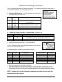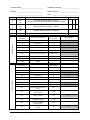
1
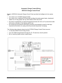
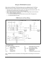
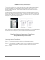
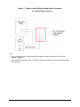
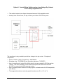
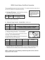
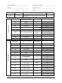
VFMQ Electric Thermal
Storage (ETS) Heater
Control Options and
Wiring Manual
Off-Peak Timing Control Options /
Automatic vs Manual Charge Control
2
Automatic Charge Control Wiring /
DCP2010 Charge Control Panel
3
Wiring the TS521W Wall Thermostat /
VFMQ Control and Power Wiring
4
Wiring the RTEV99 Internal Thermostat
5
Manual Charge Control Options
6
Wiring to a Utility-Supplied Contactor
7
Wiring to a Utility-Supplied LV Dry Contact
8
Wiring to a Timer
9
DCP2010 Control Settings Rural Electric Cooperatives
Appendix A
DCP2010 Control Settings Nova Scotia
Appendix B
IMPORTANT SAFETY INFORMATION: Always read the installation manuals first before
attempting to install or use VFMQ storage heaters or DCP2010 charge control panels. For your
safety, always comply with all warnings and safety instructions contained in these manuals to
prevent personal injury or property damage.
To view the full line of Dimplex products, please visit www.dimplex.com
7211270100 Rev03
VFMQ Storage Heater
Off-Peak Timing Control Options
VFMQ storage heaters are designed to store heat during the Off-Peak period when electricity is
less expensive. The accuracy of the timing controls is critical to cost effective operation.
PLEASE NOTE. Different electric utilities use various control methodologies. Please contact
your electric utility to understand their Off-Peak control procedure and if they offer an Off-Peak
timing device.
The most common alternatives:
• A utility-supplied control relay. Popular with Rural Electric Cooperatives.
• A utility-supplied dry contact on a meter. Standard for Nova Scotia.
• A timer. Standard in Ontario.
Automatic vs Manual Charge Control
Managing the amount of energy to store to meet the next day’s heating requirements can be
done automatically or manually.
1. Automatic Charge Control requires the Dimplex DCP2010 Charge Control Panel to estimate
how much heat to store to meet the next day’s heating needs. It does this by using
advanced algorithms based on temperature data and user preferences.
Automatic charge control is better:
• for sites with more than one heater.
• when low user involvement is desired.
• to individually control up to 4 additional circuit loads such as your water heater,
baseboard heaters in non-living areas or any other loads on their own circuit up to 30
Amps.
• at reducing the sizing of the storage heater in areas that offer mid-peak periods, due to
its intelligence for minimizing the use of more-expensive mid-peak power for the coldest
days.
2. Manual Charge Control allows the user to decide how much heat to store for the next day by
adjusting a knob on the side of the storage heater and:
• is less expensive, eliminating the need for the DCP2010 Charge Control Panel.
• is recommended for single heater installations.
• can be upgraded to use the DCP2010 automatic charge control system at a later time.
7211270100 Rev03
2
Automatic Charge Control Wiring
DCP2010 Charge Control Panel
Dimplex’s DCP2010 Automatic Charge Control Panel provides the intelligence for the system
and:
• can control up to 30 VFMQ storage heaters.
• can control up to 4 additional 30 Amp loads including the existing water heater, baseboard
heaters in non-living areas and any other loads on their own circuit.
• the panel is supplied with an external temperature sensor with a 2m (6.5 ft) connection cable
that can be extended to 30m (98 ft) by #16/2 wire.
• the external sensor allows the DCP2010 controller to automatically correct for the large
temperature fluctuations in spring and fall by external temperature averaging.
The following wiring diagram shows how the DCP2010 Charge Control Panel connects:
• to various Off-Peak control timing devices.
• up to 30 VFMQ storage heaters through the Z1, Z2 terminals, wired in parallel.
• Up to 4 auxiliary loads such as a water heater.
7211270100 Rev03
3
Wiring the TS521W Wall Thermostat
When wiring to the Dimplex TS521W wall thermostat, two additional fuses (F1 & F2) are
required to protect the external wiring with a minimum rating of 240 volts and 15 Amps.
• The fuses must be wired in-line from terminals 1 & 5 with fully-rated wire (#8 or #10). The
stat can then be wired with #12 or #14 from the fuse block.
• The 2 x fuse blocks can be installed within the VFMQ storage heater near the terminal
blocks. Readily available components:
• 2 x Littelfuse #LFR250301S fuse blocks that can connect #8 - #14 gauge wire.
• 2 x Littelfuse #FLNR-015 fuses.
VFMQ Control and Power Wiring
Ground
Note. Installation must be in accordance of the wiring codes for load sizing of the circuits and
wiring.
7211270100 Rev03
4
Wiring the RTEV99 Internal Thermostat
As per the RTEV99 Instructions, fasten the sensor probe assembly by the supplied screws on
the base next to the fan. There are four wires:
• The white wire marked LE is wired into lower terminal block #7.
• The white wire marked LH is wired into lower terminal block #10.
• The two wires crimped together are wired to the lower terminal block #8 and jumpered to the
upper terminal block #5 / N.
• The brown wire marked L is pre-wired to a 2-pole terminal block at #12. This terminal block
is to be connected to the pre-drilled holes under the main terminal block and then wired to
upper terminal block #2 – L1 to complete the circuit.
Wiring by installer
- - - - Pre Wired
7211270100 Rev03
5
VFMQ Manual Charge Control Option
To reduce the installation cost in homes that require only a single storage heater, the heater’s
heat storage charging can be controlled manually eliminating the need for the DCP2010
automatic charge control panel. Every Dimplex storage heater has manual charge control
functionality built in.
This manual charge control option allows the homeowner to manually decide how much heat
energy to store during the next Off-Peak period. No charge is the zero setting (▼), while a full
charge for those coldest days (January and February) would be a three (III). The typical winter
setting is 2 (II), spring and fall is typically set at 1.
Note: The photo on the left shows the manual charge control knob on top. The middle switches
and the second knob in the photo are part of the RTEV99 internal thermostat option.
Wiring Specifications to Connect various Timing Devices
Using the Manual Charge Control Option
Connecting to Various Timing Devices:
Option 1. The most common method is directly via a utility-supplied contactor.
Option 2. A utility-supplied low voltage dry contact in which a voltage needs to be provided to
open and close contacts. This method is common in Nova Scotia, Canada.
Option 3. A timer.
7211270100 Rev03
6
Option 1. Typical Control Wiring Solution with a Contactor
in a Utility-Supplied Device
Note:
• Use a “normally open” contact if the Utility signal is an open contact for the Off-Peak
periods. (Shown)
• Use a “normally closed” contact if the Utility signal is a closed contact for Off-Peak periods.
(Not Shown)
7211270100 Rev03
7
Option 2. Control Wiring Solution using a Low Voltage Dry Contact
from a Utility-Supplied Device
•
•
This method requires low voltage to be passed across a Utility-supplied contact.
Used by Nova Scotia Power, the dry contact is part of their Time-Of-Day meter.
The transformer is only needed to provide low voltage to the dry contact. Examples of
components:
• Marcus 12/240 to 12/24 AC transformer - MRCMO50A.
• Schneider relay - TLPRPM21B7 and Schneider relay base - TLPRPZF2.
• Use a “normally open” contact if the Utility signal is an open contact for Off-Peak periods.
(Shown) This is the standard in Nova Scotia and requires the NSPi meter lead wire
#113397 to connect to the NSPi meter dry contact.
• Use a “normally closed” contact if the Utility signal is a closed contact for Off-Peak periods.
(Not Shown)
• The suggested transformer and relay panel dimensions are 8” w x 8” h x 4” d.
7211270100 Rev03
8
Option 3 – Control Wiring Solution using a Timer
•
•
•
•
•
Used in lieu of a utility-supplied timing device.
An example is Ontario where the Smart Meters do not include physical contacts to
synchronize the system to.
This solution requires an accurate timer programmed with the Utility's Off-Peak
schedule. An example is the Intermatic ET1725C with 7 day programmability, battery
backup and changes automatically for daylight savings time.
The timing device must be rated for switching 240 volts.
In this application, the storage heater will charge when the timer is in “off mode”. The timer
must open the control circuit during Off-Peak periods and close for Peak periods.
7211270100 Rev03
9
Dimplex North America Limited
1367 Industrial Road
Cambridge, Ontario
Canada N1R 7G8
www.dimplex.com
For more information, please contact:
Brian Reid, Solutions Manager
(519) 650-3630 x339
[email protected]
7211270100 Rev03
10
DCP2010 Control Settings - Rural Electric Cooperatives
This is a simplified document for trained contractors. For complete instructions, please refer to
the DCP2010 Installation and Operating Instructions
a) Setting the DIP Switches. The DIP switches are located
on the PCB board within the enclosure.
Position
Set Switch
8
OFF
Description
Rate Signaling, Closed contact for
Off-Peak
WARNING:
Ensure all circuits are deenergized before opening
control enclosure as there
may be up to five live
circuits
NOTE: this DIP Switch must be changed to “ON” if the Utility
uses an open contact for Off-Peak times
b)
Setting the Charge Controller – Operator Mode. Installer to set.
Uhr:
Enter Set
Points
Ja, set time
TAE:
Day
ANZ
AU
Selection
Timer (Ja =YES) Set time based on a 24h-Clock
Setting the day: T1=Monday, T2=Tuesday, T3=Wednesday,
T4=Thursday, T5=Friday, T6=Saturday, T7=Sunday
Real-Time display
c) Setting the Charge Controller – Technician Mode
To set in Technician mode, press the black button as shown
on the right. The red LED will illuminate.
In Technician Mode, installers must set the following based on
the length of the Utility’s Off-Peak period.
Selection
E1
E3
TU:
SEH
•
•
•
8hr (Off-Peak)
Enter Set Points
-24
7h
9h
0h
10hr (Off-Peak)
Enter Set Points
-24
9h
11h
0h
12hr (Off-Peak)
Enter Set Points
-24
11h
13h
0h
Description
Full charge setting
Main charge duration
All other settings to be left at factory defaults.
After these selections, press button to de-select Technician Mode. Red LED will turn off.
If Mid-Peak rates are available, please contract Dimplex @ 1-800-668-6663 x339.
NOTE. Installer to fill out the following commissioning table and leave with the
homeowner for their records.
DCP2010 Control Settings – Rural Electric Cooperatives
Appendix A
Customer Name: ________________________
Installation Company: _____________________
Address: _______________________________
Installer Phone #: ________________________
_______________________________
Date___________________________________
Set switch to:
8
Off
Technician Menu
Operator Menu
Position
Description
Enter Setting
Rate Signaling (Closed contact for Off-Peak, this DIP Switch
must be changed to “ON” if the Utility uses an open contact for
Off-Peak times
Operator menu
abbreviation
Operator menu designation
Operator menu
factory default
Enter Setting:
LA
Runtime
0h
0h
E5
Charge level
0%
0%
E2
Charge start
15° C
15° C
E15
Base charge start
15 %
15 %
E10
Additional charging
85 %
85 %
ATW
Effective external temperature
External
temperature
display
Timer
Real-time timer
No
TAE
Day setting
T1
ANZ
Display
Enter Setting:
Technician menu
abbreviation
Technician menu designation
Technician menu
factory setting
E1
Full charge
- 12° C
E3
Main charging duration
7h
E4
Minimum charging base
25 %
25%
TAS
Daytime skip
E1
E1
TU
Daytime switching
10 h
SEH
Lock
6h
UMD
Circulation period
22 h
22 h
ATM
External temperature
averaging
Yes
Yes
FSU
Release synchronization with
timer
No
No
LFS
Earliest
start of release
23:00
23:00
LFD
Maximum
duration of release
8h
8h
LZS
Earliest start
of additional release
14:00
14:00
LZD
Maximum additional
release duration
0h
0h
SHT
Daytime heating contactor
activation
No
DCP2010 Control Settings – Rural Electric Cooperatives
No
Appendix A
DCP2010 Control Settings - Nova Scotia
This is a simplified document for trained contractors. For complete instructions, please refer to
the DCP2010 Installation and Operating Instructions
a) Setting the DIP Switches. The DIP switches are located on the
PCB board within the enclosure.
Position
Set Switch
Description
1
2
3
4
5
6
7
8
Off
Off
On
On
On
Off
Off
On
Mid-Peak Off-Set (in hours): 5 hours
(the time from the end of Off-Peak to the start
of the Mid-Peak)
b)
WARNING:
Ensure all circuits are
de-energized before
opening control
enclosure as there may
be up to five live circuits
Mid-Peak Duration (in hours ): 4 hours
Stepped delay 5 minutes in sequence
Rate Signaling Open contact for Off-Peak
Setting the Charge Controller – Operator Mode. Installer to set.
Selection
Uhr:
Enter Set Points
Ja, set time
TAE:
Day
ANZ
AU
Timer (Ja =YES) Set time based on a 24h-Clock
Setting the day: T1=Monday, T2=Tuesday, T3=Wednesday,
T4=Thursday, T5=Friday, T6=Saturday, T7=Sunday
Real-Time display
c) Setting the Charge Controller – Technician Mode.
To set in Technician mode, press the black button as shown on the
right. The red LED will illuminate.
In Technician Mode, contractors must set the following:
Selection
E1
TU:
SEH
FSU
LFS
LZS
LZD
•
•
•
Enter Set
Points
See Table B
9 hr
0 hr
Ja
23:00
12:00
4hr
Description
Table B - Area
E1 Setting
Real Clock Timer
Start of Off-Peak period
Start of Mid-Peak period
Length of Mid-Peak period
Amherst
Halifax
Kentville
New Glasgow
Sydney
Truro
Yarmouth
-7
-4
-5
-7
-4
-7
-2
All other settings to be left at factory defaults.
After these selections, press button to de-select Technician Mode. Red LED will turn off.
Note. E1 is typically set to the outdoor design temperature (°C) for 8+0, but as we’re using
the Mid-Peak (8+4), E1 is reduced to minimize the use of more expensive Mid-Peak energy.
NOTE. Installer to fill out the following commissioning table and leave with the
homeowner for their records.
DCP2010 Control Settings – Nova Scotia
Appendix B
Customer Name: __________________________
Installation Company: _____________________
Address: ________________________________
Installer Phone # ________________________
________________________________
Date: __________________________________
Set switch
Off
Off
On
On
On
Off
7
Off
Stepped delay 5 minutes in sequence
8
On
Rate Signaling, Open contact for Off-Peak
Technician Menu
Operator Menu
Position
1
2
3
4
5
6
Description
Enter Setting
Mid-Peak Off-Set (in hours) 5 hours
(the time from the end of off-peak to the start of mid-peak)
Mid-Peak Duration (in hours ) 4 hours
Operator menu
abbreviation
Operator menu designation
Operator menu
factory default
Enter Setting:
LA
Runtime
0h
0h
E5
Charge level
0%
0%
E2
Charge start
15° C
15° C
E15
Base charge start
15 %
15 %
E10
Additional charging
85 %
85 %
ATW
Effective external temperature
External
temperature display
Timer
Real-time timer
No
TAE
Day setting
T1
ANZ
Display
Technician menu
abbreviation
Technician menu designation
Technician menu
factory setting
E1
Full charge
- 12° C
E3
Main charging duration
7h
7h
E4
Minimum charging base
25 %
25%
TAS
Daytime skip
E1
E1
TU
Daytime switching
10 h
SEH
Lock
6h
UMD
Circulation period
22 h
22h
ATM
External temperature averaging
Yes
Yes
FSU
Release synchronization with
timer
No
LFS
Earliest
start of release
21:00
LFD
Maximum
duration of release
8h
LZS
Earliest start
of additional release
14:00
LZD
Maximum additional
release duration
0h
SHT
Daytime heating contactor
activation
No
DCP2010 Control Settings – Nova Scotia
Enter Setting:
8h
No
Appendix B