1
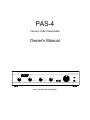
PAS-4
Vacuum Tube Preamplifier
Owner's Manual
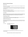
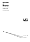
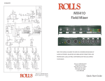
VACUUM TUBE PREAMPLIFIER
R
PAS-4
CD
VIDEO
AUX
SOURCE
TUNER
2 to 1
SOURCE
TAPE 1
1 to 2
TAPE 2
LEFT
RIGHT
EPL
PHONO
IN
INPUT
TAPE DUBBING
TAPE MONITOR
BALANCE
PAS-4 Vacuum Tube Preamplifier
MONO
IN
VOLUME
POWER
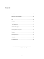
Contents
Introduction ...................................................................................... 3
Rear Panel Inputs and Outputs ....................................................... 4
Fuse ................................................................................................. 4
Operation ......................................................................................... 5
Tube Replacement .......................................................................... 7
Alternate Tube Types ...................................................................... 8
Minimizing Noise in the System ...................................................... 9
Warranty .......................................................................................... 10
PAS-4 Specifications ....................................................................... 11
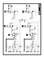
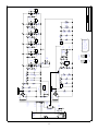
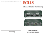
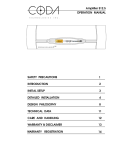
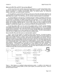
Schematics ...................................................................................... 12
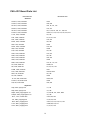
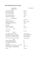
PC Board Parts List ......................................................................... 14
Please read this manual thoroughly before operating your new PAS-4.
2
Introduction
Congratulations on your purchase of the Dynaco PAS-4 preamp. This preamplifier
was designed to provide the highest combination of quality and value available,
which is the Dynaco tradition.
Only very high quality components have been used in manufacturing the PAS-4.
Examples of this are the low noise metal-film resistors, polypropylene film
capacitors, and selected (tested) vacuum tubes. Likewise, the high quality rotary
switches and potentiometers provide better performance and reliability than what is
found in most other audio equipment.
Unique to this modern PAS-4 vacuum tube design is its power supply buffering
circuitry - found in no other preamp of this class. We have included a separate
buffer circuit for each of its six tubes, allowing each amplification stage to function
more independently, (as if each has its own separate power supply). This
contributes significantly to the extraordinary sonic clarity of the PAS-4.
The PAS-4 contains a true state-of-the-art phono preamp section. It provides a
front panel switched "external processing loop" for use with a graphic equalizer or
other signal processing equipment. It also includes full provisions for tape dubbing
between two tape decks ("1 to 2" and "2 to 1").
You will find the PAS-4 to sound better than the large majority of other
preamplifiers - both solid state and vacuum tube designs - regardless of price. Its
flexibility and full-featured styling is without parallel in affordable preamps. Your
PAS-4 was designed and built entirely in the USA. We are proud to offer this
outstanding preamplifier to discerning audiophiles the world over.
Dynaco Engineering Group
3
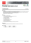
Rear Panel Inputs and Outputs
Inputs - Phono
These inputs will accommodate "moving magnet" or high output "moving coil" cartridges which have
output levels of 1.0mV or higher.
In the lower right hand corner of the rear panel is the preamp's chassis ground terminal. This thumbscrew
is provided for attaching the separate ground wire often provided on turntables. (see Minimizing System
Noise on page 11)
Inputs - Tuner, CD, Video, Aux., Tape 1 & 2
These inputs receive standard line (high level) input signals from other equipment. The Tape Inputs of the
PAS-4 connect to Line Outputs (Play) on tape decks.
Tape Outputs
Signals sent to these outputs are at line level. (Phono signals are first amplified and equalized). Tape
Outputs are unaffected by external processing circuits, the Mono switch, the Volume control, or the
Balance control. The preamp's Tape Outputs connect to the tape deck(s) Line (Record) Inputs .
Preamplifier Main Outputs
Two pairs of outputs are provided for your power amplifier(s). The two left channel RCA jacks are
connected directly together inside of the PAS-4, as is the right channel pair.
EQ (External Processing Loop)
"EQ Out" are line level outputs which can be connected to the inputs of an external signal processor such
as an equalizer, time delay, or noise reduction unit. "EQ In" are for line level inputs coming from the signal
processor outputs.
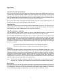
FUSE
AC Line Fuse:
2 Amp Fast-Blow - 100 or 115 VAC
1 Amp Fast-Blow - 230 VAC
120
PUSH TAB TO RELEASE FUSE HOLDER
To remove the AC line fuse, use a small screwdriver to push forward the tab near the center of the
Power Entry Module.
Always remove the power cord when accessing the AC line fuse.
4
Operation
Turn-On Delay and Visual Indicator
When you turn on the PAS-4, the lamp above the PWR (power) switch glows GREEN and a timer circuit
is evoked which keeps the preamp outputs at zero volts during the warm-up period. This 45-second
warm-up period allows the tube filaments to fully heat, the high-voltage section of the power supply to
reach full potential, and for the preamp output circuitry to settle, (avoiding loud turn-on "thumps"). When
warm-up is finished, the lamp turns to RED and the preamp outputs are operative.
When you turn off the PAS-4, the outputs immediately clamp to zero volts. Turning the preamp back on at
this point will require, again, waiting through the warm-up period.
Input Selection
Your choice of a signal source is indicated by the INPUT switch position you select. This signal source is
what you will hear. It is also sent to the Tape (recording) Outputs and the EQ Outputs, (as long as the
TAPE MONITOR and TAPE DUBBING switches are both set to SOURCE).
Tape Deck Selection - Listening
You may bypass the INPUT switch selection by using the TAPE MONITOR switch, in which case the
signal from the selected tape deck is what you will hear and what is sent to the EQ Out jacks.
When the TAPE MONITOR switch is turned to Tape 1 or Tape 2, what you hear is the signal from the
tape deck playback head, not the original source signal (which is being recorded onto tape via the tape
deck record head). This feature allows direct comparison of the signal source with taped replica without
affecting the recording process. (If a tape deck does not have separate record and playback heads, then
the signal you hear when using the TAPE MONITOR switch is the same signal being sent to the tape
deck to be recorded.)
The following controls affect all signals which are heard through the speakers.
They have no effect, however, on signals being recorded at the Tape Outputs.
EQ Switch
Pushing IN the EQ switch inserts a signal processing device into the preamplifier signal path (if such a
device is connected to the EQ Inputs and Outputs). This part of the signal path is then called the External
Processor Loop (EPL). Such devices include equalizers, time delays or ambiance simulators, expanders,
compressors, and noise reduction systems. When the EQ switch is in the OUT position, any equipment
plugged into the EQ inputs is effectively removed from the preamplifier signal path. Therefore, an
unpowered device connected to the EQ Inputs and Outputs will not deteriorate the PAS-4's performance
(which can happen with some tape decks, as mentioned above).
Note:
The EQ inputs can also be used as a second set of Auxiliary Inputs - (for a second tuner, second
CD player, etc.) Therefore, the EQ switch itself can also function as an additional input selector.
Mono Switch
When this button is IN, left and right channel information is combined and the composite signal is fed to
both left and right outputs. In this mode the sound image should appear to be centrally located between
the loudspeakers. This switch is useful when listening to monophonic program material. It cancels the
unwanted vertical phonograph modulations which are heard as noise from monaural records.
5
Balance Control
This adjusts the proportion of left and right channel signals going to the preamp's line level amplification
stage (and therefore to the preamp's main outputs). Only the left channel signal will be heard with the
Balance Control turned fully counter-clockwise, and only the right channel signal with full clockwise
rotation. The function of the Balance Control is to compensate for unbalanced left and right channel signal
levels (from phonograph records, for instance) or to compensate for non-symmetrical room acoustics
(from furniture, wall reflections, etc.).
Tape Deck Selection - Recording
The TAPE DUBBING switch determines which signals are sent to the tape decks for recording purposes.
If the TAPE DUBBING switch is set to SOURCE, both tape decks receive the same signal - the one
indicated by the position of the INPUT switch.
A copy of a tape can be made when the TAPE DUBBING switch is set to either ‘2 to 1’ or ‘1 to 2’. (When
this is done, the signal source selected by the INPUT switch is disconnected from both tape decks.)
When the TAPE DUBBING switch is set to ‘2 to 1’, the output of tape deck #2 goes to the input of tape
deck #1 to be recorded. When the TAPE DUBBING switch is set to "1 to 2", the output of tape deck #1
goes to the input of tape deck #2 to be recorded.
The TAPE MONITOR switch can be used to listen to the "source" tape deck (the original recording) or the
"target" tape deck (the dubbed recording) while tape dubbing is being done. However, if the TAPE
MONITOR switch is set to SOURCE, one can listen to any music signal selected with the INPUT switch
while tape dubbing is in progress.
___________________________________________
Note:
Some older tape decks which do not have high impedance input circuitry can present non-linear
loads to a preamp's Tape Outputs even when the tape decks are turned off. This can be a
problem because the Tape Outputs are usually connected to which ever signal source has been
selected by the INPUT switch. This “always present” non-linear load can degrade performance on
most preamps.
With the PAS-4 there is a solution to the use of lower input impedance tape decks. Simply keep the TAPE
DUBBING switch positioned to ‘1 to 2’ or ‘2 to 1’ when the deck is not in use. This disconnects the signal
selected by the INPUT switch from both tape decks, as mentioned previously.
6
Tube Replacement
CAUTION: Before replacing tubes on your PAS-4 ensure the AC power cord is un- plugged from its AC
(wall) outlet (or that the AC power cord is unplugged from the back of the unit) and wait for
three minutes to allow the high voltage power supply to discharge. Gloves may be worn
when changing tubes. Never touch live circuit elements in vacuum tube equipment because
lethal voltages are present when these are turned on.
The tubes in your PAS-4 could provide 5,000 to 10,000 hours of use. We recomend that these tubes be
replaced after no more than 3,000 hours of use to avoid the slightly "muffled" sound or slight bass "rolloff" which can begin to occur with old tubes.
Microphonics (various "pinging" or "howling" sounds) is due to a tube being overly sensitive to physical
vibrations. To avoid it, do not operate vacuum tube equipment on top of vibrating surfaces (such as
loudspeakers). But if a tube is so sensitive that just having the preamplfier turned on causes the
microphonic sounds, the tube will have to be replaced. It can happen that a tube becomes microphonic
with age or that it is only microphonic before it warms up (or only after it warms up).
The most common type of problem in tube preamplifiers is excessive noise caused by a worn or faulty
tube. The characteristics of this noise can vary a great deal. If a noise problem occurs with your PAS-4,
99% of the time it will be due to a faulty tube
The most likely source of tube noise in the PAS-4 is the phono section first stage tubes V1 (left channel)
or V4 (right channel). Less likely, but to be suspected next, would be the phono stage second stage
tubes V2 (left) or V5 (right). If the undesirable noise increases as you turn up the volume control, the
faulty tube is likely to be one of the phono section tubes. The line stage tubes are V3 (left) and V6 (right).
(Refer to the tube numbers printed adjacent to pin #1 of each tube on the printed circuit board.)
Note: When removing a tube, grasp the tube socket with one hand and the tube with the other hand.
Move the tube (slightly) from side to side while pulling outward.
The most certain method for confirming a faulty tube
is by substitution of a known good tube.
An easy way to determine if a tube in any particular position is causing un-desirable noise is to
swap the suspected tube with its counterpart in the opposite channel. If the noise jumps to the
other channel, the tube you suspected is indeed faulty.
7
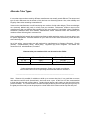
Alternate Tube Types
It is true that vacuum tubes made by different manufactures can actually sound different. The amount and
type of sonic differences can be subtle or fairly obvious to a discerning listener. Also, tube reliability and
longevity often varies according to manufacturer.
Vacuum tube manufacturers are still introducing new versions of older tube designs. These new designs
are commonly labeled with partly or wholly new part numbers. Furthermore, different vacuum tube
manufacturers often use different part numbers for their own versions of “equivalent” tubes. Distributors
sometimes substitute tubes from different manufacturers and/or substitute tubes with alternate part
numbers without informing their customers first.
Some audiophiles feel strongly about which manufacturer and/or particular version of vacuum tube to use
for specific applications. The tubes installed on your new PAS-4 have been selected to provide the best
sound and long life.
As of this writing, vacuum tubes are still produced by manufacturers in Germany (Siemens), Russia
(Sovtek), Czechoslovakia (Telsa), China (Sino), Yugoslavia (EI), and in England. Your dealer can
recommend U.S. tube distributors, if needed.
Alternate tube part numbers which can be used on the PAS-4:
Designator
Common Part Numbers
Alternate Part Numbers
V1, V4
12AX7
ECC83
V2, V3, V5, V6
6DJ8
ECC88, 6922, 7308
If tube replacement becomes necessary, Dynaco can supply you with new
vacuum tubes and/or a list of specifically recommended tubes for the PAS-4.
_______________________________________________________________________
Note: Because it is possible for oxidation to build up on vacuum tube pins, it is a good idea to remove
and clean them with a small (brass bristle) wire brush once a year. At this time it is also recommended
to clean the tube pins with contact cleaner. Contact cleaner leaves a thin coating on the pins which helps
prevent oxidation. The contact cleaner can either be sprayed directly onto the tube pins (don’t get any on
the glass part of the tube) or can be sprayed on a clean cloth which is then used to wipe the tube pins.
8
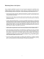
Minimizing Noise in the System
Hum is caused by amplification of the 50 or 60 Hz AC power line signal that is transmitted via the
magnetic fields around power transformers and power cables. RF interference usually comes from
inadequate shielding of cables or components. If any of these types of noises are encountered, one or
more of the following pointers concerning proper component positioning and grounding may be of use:
➣ Ensure that each system component, especially the preamplifier, is located far enough away from the
other components so that they will not pick up hum from them, and that the AC power cables are not
in close proximity to audio cables.
➣ Ensure that all audio cables are securely pushed into their respective jacks. A faulty audio cable,
although rare, can be a source of hum if its outer shield is broken or disconnected from an RCA plug
at one end of the cable.
➣ The best “system grounding scheme” is to have your preamplifier well grounded to an earth ground
point and function as the system's main ground reference. Other system components are then quite
adequately grounded by being connected to the preamplifier’s ground via their audio cables. Using
this grounding scheme can be as simple as just plugging the preamplifier’s power cable into a three
prong AC outlet. However, if the AC outlet itself does not provide a really "good" ground, the
preamplifier power cable can be plugged into a three-to-two prong adapter and a wire can be run
from the tab on the adapter to the nearest cold water pipe.
➣ Another solution to AC power cable "ground loop" hum problems is to plug the AC power cables from
all of the system components into a common "socket strip" (available from most hardware stores).
➣ If RF noise (usually an AM radio station or CB transmission) is a problem in your area, an AC power
filter can be purchased into which some or all of your system power cords can be plugged. This is
done if the RF is coming in through the building's AC wiring. However, if RF gets into the system via
your turntable, you may have to use tonearm cables with better shielding. (This is tested by
unplugging the turntable from the system and putting "shorting plugs" in the preamplifier’s phono
inputs before listening again.) RF noise is sometimes eliminated by simply moving the turntable or
other components to another location in the room.
➣ Hum from a turntable is usually traced to an adjacent power transformer or a missing or improper
ground. Check to see that the turntable motor is grounded via a wire to the preamplifier’s grounding
post - (or try removing this wire from the ground post if it is already connected there).
9
Warranty
For three years from the date of purchase (one1 year for tubes) Dynaco will repair, for the original owner,
any defect in materials or workmanship that occurs in normal use, without charge for parts or labor.
It is the owner's responsibility to provide transportation to the authorized Dynaco service representative
who will perform warranty service, and to present proof of purchase in the form of a dated sales slip when
requesting service.
Excluded from this warranty is damage that results from abuse, misuse, accidents, shipping, repairs or
modification by anyone other than an authorized Dynaco service representative. This warranty is void if
the serial number has been removed or defaced. This warranty gives you specific legal rights, and you
may also have other rights - which vary from state to state.
If service is required, contact the dealer from whom you purchased the amplifier. If that is not possible,
write Dynaco, giving us:
✓ Your name and address
✓ Make and model of your amplifier
✓ The amplifier’s serial number
✓ When and where you purchased it (copy of sales slip)
✓ Description of the problem
✓ Whether you have the original carton and fillers or need new ones
DYNACO strongly recommends using only its performance checked pre-tested vacuum tubes. Each tube
is guaranteed to perform properly in its intended application for ONE YEAR. Orders for tubes may be paid
for by personal check or money order. Please also include $4.00 for shipping and handling.
Dynaco
A Division of Panor Corporation
125 Cabot Court
Hauppauge, New York 11788
(516) 434-1200
(516) 434-1457 FAX
10
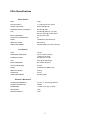
PAS-4 Specifications
Phono Section
GAIN:
40 dB
RIAA ACCURACY:
+/- .5 dB from 20 Hz to 20 kHz
PHONO OVERLOAD:
500mV RMS @ 1kHz
MAXIMUM OUTPUT CAPABILITY:
60V RMS @ 1kHz
THD:
INPUT IMPEDANCE:
50V RMS @ 20kHz (for 1% THD)
less than .025% @ 2V RMS Output
47k shunted by 10pF
TAPE OUTPUT IMPEDANCE:
2k
NOISE:
-86 dB below 10mV RMS Input
ABSOLUTE PHASE:
Non-Inverting
TUBE COMPLEMENT:
2ea 6DJ8 (6922); 2ea 12AX7 (ECC83)
Line Section
GAIN:
18.5 dB
FREQUENCY RESPONSE:
MAXIMUM OUTPUT:
2 Hz to 150 kHz (nominal)
(-3 dB, 20 k ohm load)
40V RMS (for 1% THD)
THD:
.025% @ 2V RMS Output
INPUT IMPEDANCE:
25k nominal (all inputs)
OUTPUT IMPEDANCE:
40 ohms
NOISE:
-90 dB below 2V RMS Output
ABSOLUTE PHASE:
Inverting
SLEW RATE:
40 V/µs
TUBE COMPLEMENT:
2ea 6DJ8 (6922)
Electrical / Mechanical
POWER REQUIREMENTS:
100, 115, or 230 VAC @ 50/60 Hz
POWER CONSUMPTION:
45 Watts
DIMENSIONS:
17" Wide, 3.75" High, 12" Deep
NET WEIGHT:
12 lbs.
SHIPPING WEIGHT:
14 lbs.
11
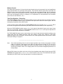
12
EQ IN
EQ OUT
TAPE 2
IN
TAPE 2
OUT
TAPE 1
IN
TAPE 1
OUT
AUX
VIDEO
CD
TUNER
PHONO
RIGHT INPUTS
EQ IN
EQ OUT
TAPE 2
IN
TAPE 2
OUT
TAPE 1
IN
TAPE 1
OUT
AUX
VIDEO
CD
TUNER
PHONO
LEFT INPUTS
2K
R102
2K
R101
2K
R2
2K
R1
8
9
8
7
9
10
1
2
3
2
3
4
16
SW4A
SW2A
22
12
11
10
SW4B
SW2B
TAPE DUBBING
19
SW1B
INPUT SELECTOR
ACTIVE
INACTIVE
EQUALIZER
19
7
11
5
6
4
TAPE DUBBING
13
SW1A
INPUT SELECTOR
ACTIVE
INACTIVE
EQUALIZER
13
1
5
8
2
7
9
1
3
19
SW3B
TAPE MONITOR
13
SW3A
TAPE MONITOR
R103
47K
FB2
R3
47K
FB1
C2
22pF
C102
2
10pF 1
C101
22pF
2
10pF 1
C1
3
6
8
R104
1.37K
8
249K
R106
-3.3V
R7
2M
249K
R6
7
-3.3V
R107
V4
12AX7 2M
.1uF
400V
C103
7
V1
12AX7
.1uF
400V
C3
R4
1.37K
R105
287K
1W
+300V
D
3
6
R5
287K
1W
+300V
A
R110
165K
C105
440pF
R108
6.49K
C104
220pF
301
R109
2
V5A
6DJ8
C6
1
7
3
3
1500pF
C106
1
7
6
6
+300V
E
1500pF
V5B
6DJ8
2
R111
301
R10
165K
C5
440pF
R8
6.49K
220pF
C4
301
R9
V2A
6DJ8
R11
301
V2B
6DJ8
+300V
B
9
R112
249
8
9
R12
249
8
R113
499K
3.3uF
400V
C107
R13
499K
3.3uF
400V
C7
R18
P1B
50K
P2B
50K
VOLUME
MONO
P2A
50K
3W RESISTORS ARE 5%, METAL OXIDE
24.9K
R119
BALANCE
24.9K
R19
BALANCE
1/2W AND 1W RESISTORS ARE 1%, METAL FILM
5.6K
R118
STEREO
SW5
5.6K
P1A
50K
VOLUME
V6B
6DJ8
2
REV B
301
R120 2
V6A
6DJ8
C108
.1uF
400V
R123
301
301
R20
V3A
6DJ8
C8
.1uF
400V
R23
301
V3B
6DJ8
6
C109
3.3uF
400V
C9
9
R126
15K
3W
3.3uF
R125 400V
221
8
9
R26
15K
3W
R25
221
8
R127
499K
140
R128
R27
499K
140
R28
8
12
19 JULY 94
PAGE
1
OF
2
K1-A
N.O.
DWG# 00501
K1-B
2
1
RIGHT
OUTPUTS
N.O.
N.C.
2
1
LEFT
OUTPUTS
10 N.C.
7
4
6
PAS-4 PREAMPLIFIER
301K
R122
R121
221
3
1
2M
R124
7
+300V
F
301K
R22
R21
221
3
1
2M
R24
7
6
+300V
C
13
1
2
4
G
L
N
2A /100V
2A /115V
1A / 230V
F1
FAST
BLOW
POWER
ENTRY
MODULE
C204
C203
R201
100
C201
.01uF
1.4KV
BLK
100V
0.0V
.01uF
1.4KV
(x 2)
AC POWER
SW7A
BRN
WHT
115V
230V BRN/WHT
50/60 Hz
100/115/230 VAC
T1
GRN
GRN
R206
30K
R205
20K
RED
RED
D4
D3
C206
33uF
450V
470
3W
R202
C219
4700uF
25V
FWB1
600V
35A
C207
1000uF
6.3V
I
19.5V @ 1A
R204
1M
1W
R203
332K
O
C220
22uF
25V
G
U1
7812
-3.3V
SOURCE
D5 THRU D11
C205
33uF
450V
D1
D2
421V @ 45mA
C221
470uF
25V
.47 ohm
3W
R216
C208
1.0uF
400V
5.1M
R207A
SW7B
V6
RIGHT
LINE
6DJ8
4
5
4
5
TIMER
V3
LEFT
LINE
6DJ8
C209
1.0uF
400V
C210
1.0uF
400V
5.1M
R207B
ON
OFF
C222
10uF
25V
R217
4.02M
C211
1.0uF
400V
R210
470
C213
.22uF
400V
ZD1
12V
G
Q1
6
2
U2
4
1
I
16
1
G O
G
Q2
IRF 830
S
D
GREEN
RED
ZD4
200V
5W
(1)
R219
470
R218
470
R212
470
I
C215
.22uF
400V
ZD5
12V
G
Q3
O
+300V
C
ZD6
200V
5W
C223
22uF
25V
G
U3
7812
S
D
Q1 - Q6 = IRF 830
ZD2, 4, 6, 8, 10, 12 = 1N5388B
ZD1, 3, 5, 7, 9, 11 = 1N5242B
D1 - D12 = 1N4007
+300V
B
D13
BI-COLOR
LED
(2)
G D S
K1
C214
.22uF
400V
ZD3
12V
FRONT VIEWS
3
D12
7812
8
R211
470
C212
22uF
250V
+300V
A
ZD2
200V
5W
555
R208
1M
R209
1M
S
D
G
Q4
C224
470uF
25V
C216
.22uF
400V
ZD7
12V
.47 ohm
3W
R220
R213
470
ZD8
200V
5W
V2
LEFT
PHONO
6DJ8
B
V1
LEFT
PHONO
12AX7
R214
470
REV
5
4
5
4
+300V
D
V5
RIGHT
PHONO
6DJ8
S
D
5
9
4
R215
470
+300V
E
ZD10
200V
5W
Q6
C218
1uF
400V
ZD11
12V
G
S
D
PAGE
2
OF
2
+300V
F
ZD12
200V
5W
DWG# 00501
PAS-4 PREAMPLIFIER
V4
RIGHT
PHONO
12AX7
S
D
19 JULY 94
5
9
4
C217
.22uF
400V
ZD9
12V
G
Q5
PAS-4 PC Board Parts List
DESCRIPTION
DESIGNATORS
Resistors
100 ohm, 1/2W, metal film
R201
140 ohm, 1/2W, metal film
R28, 128
221 ohm, 1/2W, metal film
R21, 25, 121, 125
249 ohm, 1/2W, metal film
R12, 112
301 ohm, 1/2W, metal film
R9, 11, 20, 23, 109, 111, 120, 123
470 ohm, 1/2W, metal film
R210, 211, 212, 213, 214, 215, 218, 219
1.37K, 1/2W, metal film
R4, 104
2.0K, 1/2W, metal film
R1, 2, 101, 102
5.6K, 1/2W, metal film
R18, 118
6.49K, 1/2W, metal film
R8, 108
20K, 1/2W, metal film
R205
24.9K, 1/2W, metal film
R19, 119
30K, 1/2W, metal film
R206
47K, 1/2W, metal film
R3, 103
165K, 1/2W, metal film
R10, 110
249K, 1/2W, metal film
R6, 106
301K, 1/2W, metal film
R22, 122
332K, 1/2W, metal film
R203
499K, 1/2W, metal film
R13, 27, 113, 127
1M, 1/2W, metal film
R208, 210
2M, 1/2W, metal film
R7, 24, 107, 124
4.02M, 1/2W, metal film
R217
5.1M, 1/2W, metal film
R207A, 207B
287K, 1W, metal film
R5, 105
1M, 1W, metal film
R204
.47 ohm, 3W, metal oxide
R216, 220
470 ohm, 3W, metal oxide
R202
15K, 3W, metal oxide
R26, 126
Capacitors
10pF, 630V, polystyrene
C1, 101
22pF, 630V, polystyrene
C2, 102
220pF, 400V, polypropylene 5%
C4, 5A, 5B, 104, 105A, 105B
1500pF, 400V, polypropylene 5%
C6, 106
.01uF, 1.4 kV, ceramic disc
C201, 203, 204
.1uF, 400V, polypropylene
C3, 8, 103, 108
.22uF, 400V, polypropylene
C213, 214, 215, 216, 217, 218
1.0uF, 400V, polypropylene
C208, 209, 210, 211
3.3uF, 400V, polypropylene
C7, 9, 107, 109
14
PAS-4 PC Board Parts List (cont.)
DESCRIPTION
DESIGNATORS
Capacitors (cont.)
10.uF, 25V, alum electrolytic
C222
22uF, 25V, alum electrolytic
C220, 223
22uF, 250V, alum electrolytic
C212
33uF, 450V, alum electrolytic
C205, 206
470uF, 25V, alum electrolytic
C221, 224
1000uF, 6.3V, alum electrolytic
C207
4700uF, 25V, alum electrolytic
C219
Semiconductors
1N4007 (1A, 1kV)
D1 thru D12
1N5242B (12V, 1/2w Zener)
ZD1, 3, 5, 7, 9, 11
1N5388 (200V, 5w Zener)
ZD2, 4, 6, 8, 10, 12
3506 (35A, 600 PIV Bridge Rectifier)
FWB1
7812 (Regulator)
U1 ,3
555 (Timer)
U2
LED, Bi-Color, (red/green)
D13
IRF 830 (N-Channel FET)
Q1 thru Q6
Tubes
12AX7 (ECC83)
V1, 4
6DJ8 (6922)
V2, 3, 5, 6
Switches
Switch, pushbutton, 2 pole / 2 position
SW7 (AC power)
Switch, pushbutton, dual 2 pole / 2 position
SW4/ 5 (stereo/mono, EQ)
Switch, rotary, 2 pole / 5 position P/N 333125
SW1 (input selector)
Switch, rotary, 4 pole / 3 position P/N 333124
SW2 (tape dubbing)
Switch, rotary, 2 pole / 3 position P/N 333124
SW3 (tape monitor)
Misc.
50K, dual VOLUME potentiometer
P1
50K, dual BALANCE potentiometer
P2
Relay (DPDT) P/N DS2YE-S-DC12V
K1
Ferrite Beads
FB1, 2
Fuse, fast-blow, 2A for 100 or 115VAC - 1A for 230VAC
F1
RCA Jack Assembly - 2x2 P/N RJ-PCM-204
JA1, 2, 3, 4, 5, 7
RCA Jack Assembly - 1x2 P/N RJ-PCM-102
JA6
PC Board
17-0382-B
15