1
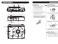
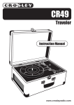
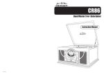
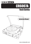
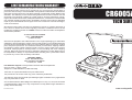
LIMITED MANUFACTURERS WARRANTY Crosley Radio, Inc. warrants the product to be free from defects in material and workmanship under normal use for a period of one year from the original date of purchase. This warranty is not transferable. If the product is determined to be defective during the warranty period, the unit will be repaired or replaced at Crosley Radios sole discretion. This warranty covers manufacturing defects and normal consumer use and does NOT cover damage or failure as a result of abuse, accident, alterations, misuse, neglect, abnormal wear and tear, inadequate maintenance, commercial or unreasonable use, damage caused by power surges, mishandling, accident, acts of God or attempted repair by an unauthorized service agent. Also not covered are cosmetic damages, cords and antennas. CR6005A TECH SERIES Should this product fail to function in a satisfactory manner, it is best to first return it to the store or retailer where it was originally purchased. If additional service is still needed, the original purchaser must FIRST contact our offices to obtain an RA (Return Authorization) Number. TO OBTAIN AN RA NUMBER CALL: 1.888.CROSLEY (1.888.276.7539) Send the unit prepaid to the address below in the original packaging (or reasonable substitute to prevent damage). Clearly mark your RA number on the outside packaging and include the original sales receipt (or a copy) indicating date of purchase, amount paid, and place of purchase. You must also include your full name, shipping address and daytime contact number. Please include a check or money order in the amount of $19.95, made payable to Crosley Radio, to cover handling and return shipping charges. Returned products will not be shipped to PO Boxes. Crosley Radio will not be responsible for delays or unprocessed claims resulting from a purchasers failure to provide any or all of the necessary information. CROSLEY RADIO ATTN: RETURNS DEPT 2001 PRODUCTION DRIVE Louisville, KY 40299 For additional support: Crosley Radio Consumer Service Department 24 hours a day / 7 days a week Telephone: 1.888.CROSLEY (1.888.276.7539) There are no express warranties except as listed above. The purchasers bill of sale is the only proof of warranty entitlement. This warranty gives the purchaser specified legal rights in addition to any rights which may vary from state to state. In accordance with the Moss-Magnuson Warranty Act of July 10, 1975, this is termed a limited warranty which in no way compromises Crosley Radios high standards of quality and workmanship. 910-290800-0010-200 www.crosleyradio.com General Troubleshooting There is no Power 1 Make sure radio is plugged in correctly. 2 The unit is not turned on: Rotate the VOLUME ON/OFF KNOB from the OFF position past the click to turn on the unit. There is no Sound 1 Check the volume level by turning the VOLUME ON/OFF KNOB. 2 Make sure headphones are not connected to the unit. 3 Check the position of the FUNCTION SWITCH. Turntable will not work 1 Make sure the FUNCTION SWITCH is set to phono. 2 Try moving the tone arm to the right until you hear a click. 3 Make sure the protective needle cover is removed. WARNING: TO PREVENT FIRE OR SHOCK HAZARD, DO NOT EXPOSE THIS APPLIANCE TO RAIN OR MOISTURE. DO NOT REMOVE COVER. PILOT LAMPS SOLDERED IN PLACE. NO USER SERVICEABLE PARTS INSIDE. REFER SERVICING TO QUALIFIED SERVICE PERSONNEL. CAUTION RISK OF ELECTRIC SHOCK DO NOT OPEN The lighting flash with arrowhead symbol, within an equilateral triangle, is intended to alert user to the presence of uninsulated "dangerous voltage" within the product's enclosure that may be of sufficient magnitude to constitute risk of electric shock to persons. CAUTION: TO REDUCE THE RISK OF ELECTRIC SHOCK, DO NOT REMOVE COVER (OR BACK). NO USER - SERVICEABLE PARTS INSIDE. REFER SERVICING TO QUALIFIED SERVICE PERSONNEL. The exclamation point within an equilateral triangle is intended to alert user to the presence of important operating and maintenance (servicing) instruction in the literature accompanying the appliance. Ventilation not being impeded. Do not exposed to dripping or splashing and that no objects filled with liquids, such as vases, shall be placed on the apparatus. Specification FREQUENCY : POWER SOURCE ANTENNA : : POWER CONSUMPTION SPEAKER SIZE SPEAKER OHM SPEAKER WATT POWER OUTPUT REPLACEMENT NEEDLE : : : : : : FM 88 -108 MHz AM 530 - 1700 KHz AC Adaptor AC120V/DC 9V 600mA External antenna for FM Built-in ferrite bar for AM 12W 2" x 3" Dynamic type x 2 4 ohm 3-5W 1.2W x 2 NP1 *DESIGN AND SPECIFICATIONS SUBJECT TO CHANGE WITHOUT NOTICE. 8 Basic Operation Welcome Turntable Operation Thank you for purchasing the Crosley Tech Series Turntable (CR6005A). Before operating this unit, please read this manual thoroughly and retain it for future reference. Radio Operation Turn the unit on by rotating the VOLUME ON/OFF 1 Set the FUNCTION SWITCH to RADIO mode. KNOB located on the front panel to the ON position 2 Set the AM / FM / FM.ST SWITCH to the desired Band. 3 Select the desired radio station by rotating TUNING KNOB . 4 Adjust the VOLUME ON/OFF KNOB to the desired sound level. 1 Set the FUNCTION SWITCH to PHONO mode. 2 Set the SPEED CONTROL SWITCH to the desired speed (33 1/3, 45 or 78 rpm). Place your record onto the turntable. 3 Move the TONE ARM slightly to the right side until you hear a click sound to activate the turntable. 4 Move the TONE ARM by hand over the record to the point you want the record to start. Adjust the VOLUME ON/OFF KNOB to your desired listening level. 5 At the end of the record, the TONE ARM will stop automatically. You must return the TONE ARM to the arm rest by hand. Accessory: Adapter for 45 rpm This adaptor allows you to play 45 RPM records. 1 Place the 45 RPM adaptor over the spindle. 2 Gently place your 45 RPM record onto the turntable. 3 Follow the steps under turntable operation to play your record. 6 About This Manual Instructions in this manual describe the control function of the CR6005A. Included in the package: Tech Series Turntable 3.5mm Stereo cable AC Power Adaptor Table of Contents Getting Started Control Locators.......................4 Unpacking................................ 5 Power Source.......................... 5 Basic Operation Turntable Operation................. 6 Radio Operation....................... 6 Connecting Optional Equipment Antenna Antenna: for FM reception, the unit is provided with a FM WIRE ANTENNA , move the wire until the reception is clear and with no interferences. For AM reception, the unit is provided with a directional build-in ferrite antenna. Rotate the set to find the position in which the best reception is obtained. Do not connect the EXTERNAL FM ANTENNA to any outside antenna. Auxiliary Output ...................... 7 Auxiliary Input.......................... 7 General Troubleshooting Guide.......... 8 Warranty.............................. 9 IMPORTANT SAFETY INSTRUCTION Connecting Optional Equipment PLEASE READ CAREFULLY ALL THE FOLLOWING IMPORTANT SAFEGUARDS THAT ARE APPLICABLE TO YOUR EQUIPMENT 1. 2. 3. 4. 5. Read Instructions - All the safety and operating instructions should be read before the product is operated. Retain instructions - The safety and operating instructions should be retained for future reference. Heed Warnings - All warnings on the product and in the operating Instructions should be adhered to. Follow Instructions - All operating and use instructions should be followed. Cleaning - Unplug this product from the wall outlet before cleaning. Do not use liquid cleaners or aerosol cleaners.Use a damp cloth for cleaning. 6. Attachments - Do not use attachments not recommended by the product manufacturer as they may cause hazards. 7. Water and Moisture - Do not use this product near water - for example, near a bath tub, wash bowl, kitchen sink, or laundry tub; in a wet basement; or near a swimming pool; and the like. 8. A product and cart combination should be moved with care. Quick stops, excessive force, and uneven surfaces may cause the product and cart combination to overturn. 9. Ventilation - Slots and openings in the cabinet are provided for ventilation and to ensure reliable operation of the product and to protect it from overheating, and these openings must not be blocked or covered, The openings should never be blocked by placing the product on a bed, sofa, rug, or other similar surface. This product should not be placed in a built - in installation such as a bookcase or rack unless proper ventilation is provided or the manufacturer's instructions have been adhered to. 10. Power Sources - This product should be operated only from the type of power source indicated on the marking label, if you are not sure of the type of power supply to your home. Consult your product dealer or local power company.For products intended to operate from battery power, or other sources, refer to the operating instructions. 11. Grounding or Polarization - This product may be equipped with a polarized alternating-current line plug (a plug having one blade wider than the other). This plug will fit into the power outlet only one way. This is a safety feature. If you are unable to insert the plug fully into the outlet try reversing the plug, If the plug should still fail to fit, contact your electrician to replace your obsolete outlet. Do not defeat the safety purpose of the polarized plug. 12. Power - Cord Protection - Power - supply cords should be routed so that they are not likely to be walked on or pinched by items placed upon or against them, paying particular attention to cords at plugs, convenience receptacles, and the point where they exit from the product. AC 13. Lightning - For added protection for this product during a lightning storm, or when it is left Polarized Plug unattended and unused for long periods of time, unplug it from the wall outlet and disconnect the antenna or cable system. This will prevent damage to the product due to lightning and power - line surges. 14. Power Lines - An outside antenna system should not be located in the vicinity of overhead power lines or other electric light or power circuits, or where it can fall into such power lines or circuits. When installing an outside antenna system, extreme care should be taken to keep from touching such power lines or circuits as contact with them might be fatal. 15. Overloading - Do not overload wall outlets, extension cords, or integral convenience receptacles as this can result in a risk of fire or electric shock. 16. Object and Liquid Entry - Never push objects of any kind into this product through openings as they may touch dangerous voltage points or short - out parts that could result in a fire or electric shock. Never spill liquid of any kind on the product. 17. Servicing - Do not attempt to service this product yourself as opening or removing covers may expose you to dangerous voltage or other hazards. Refer all servicing to qualified service personnel. 18. Damage Requiring Service - Unplug this product from the wall outlet and refer servicing to qualified service personnel under the following conditions; a. When the power-supply cord or plug is damaged. b. If liquid has been spilled, or objects have fallen into the product. c. If the product has been exposed to rain or water. d. If the product does not operate normally by following the operating instructions. Adjust only those controls that are covered by the operating instructions as an improper adjustment of other controls may result in damage and will often require extensive work by a qualified technician to restore the product to its normal operation. e. If the product has been dropped or damaged in any way. f. When the product exhibits a distinct change in performance - this indicates a need for service. 19. Replacement Parts - When replacement parts are required, be sure the service technician has used replacement parts specified by the manufacturer or have the same characteristics as the original part. Unauthorized substitutions may result in fire, electric shock, or other hazards. 20. Safety Check - Upon completion of any service or repairs to this product, ask the service technician to perform safety checks to determine that the product is in proper operating condition. 21. Wall or ceiling Mounting - The product should be mounted to a wall or ceiling only as recommended by the manufacturer. 22. Heat - The product should be situated away from heat sources such as radiators. Heat registers, stoves, or other products (including amplifiers) that produce heat. WARNING: Changes or modifications to this unit not expressly approved by the party responsible for compliance could void the users authority to operate the equipment. NOTE: This equipment has been tested and found to comply with the limits for a Class B digital device, pursuant to Part 15 of the FCC Rules. These limits are designed to provide reasonable protection against harmful interference in a residential installation. This equipment generates, uses, and can radiate radio frequency energy and, if not installed and used in accordance with the instructions, may cause harmful interference to radio communications. However, there is no guarantee that interference will not occur in a particular installation. If this equipment does cause harmful interference to radio or television reception, which can be determined by turning the equipment off and on , the user is encouraged to try to correct the interference by one or more of the following measures: - Reorient or relocate the receiving antenna. - Increase the separation between the equipment and receiver. - Connect the equipment into an circuit different from that to which the receiver is connected. - Consult the dealer or an experienced radio TV technician for help. Headphone Jack Operation Auxiliary Output 1 You can connect your radio to different sources using the auxiliary output. 2 Plug Auxiliary cables (not supplied) into the LINE OUT JACK. 3 Connect the other end of the Auxiliary cables into the input on your desired component. 4 See the owners manual for the component for correction operation. NOTE: The Auxiliary Output is a passive signal level output only and will not power speakers. 1 2 Connect headphones to the Headphone Jack Adjust volume to the desired listening level. NOTE: When using headphones, the sound to the unit speakers will be cut off. Headphone Jack The sound from all speakers is cut off. NOTE: Headphones not included with unit. Auxiliary Input 1 You can connect external components to your unit by using the Auxiliary Input. 2 Plug Auxiliary cable into the LINE IN JACK on the back of your unit. 3 Set the FUNCTION SWITCH to LINE IN mode 4 Plug the other end of the Auxiliary cable into the output jack on your desired external componet 5 Check the volume level of your external component. 6 See operators manual for correct operation of the external component. 7 Control Locators Getting Started POWER INDICATOR FM.ST INDICATOR Lid Installation Unpacking SPEAKER RADIO/ PHONO/LINE IN SWITCH VOLUME ON/OFF KNOB EARPHONE JACK DIAL SCALE AM\FM\ FM.ST SWITCH AC ADAPTOR JACK LINE OUT JACK EXTERNAL FM ANTENNA LINE IN JACK LID PIVOT POINT LOCK HINGE 1 Remove packing materials from unit. Note: Save all packing materials. 2 Remove plastic bag covering radio. 3 Remove AC Adaptor from packing. 4 Untie antenna wire on back of radio. 5 Remove black tie-wrap from under the tone arm. 6 Remove white protective needle cover by gently pulling towards the front of the unit. 7 Install the top lid onto the unit 8 Untie the FM antenna and allow it to hang down in a straight line for optimum FM reception. If you have trouble tuning in an FM Station, move the external FM antenna for best reception. Do not connect FM antenna to outside antenna 1 Flip the LID LOCK HINGE towards the back of the unit. SPEAKER TUNING KNOB LID PIVOT POINT 2 Position LID over the turntable and press the lid onto the LOCK HINGE as shown below. click 3 As you press the lid into place, align the PIVOT PINS on the LID with the LID PIVOT POINTS as shown below. SPEED CONTROL SWITCH 4 Press the LID all the way in until the PIVOT PINS snap into the LID PIVOT POINTS and the LOCK HINGE clicks into place. TONE ARM REST Power Source TONE ARM 4 ADAPTER FOR 45 RPM RECORDS SPINDLE TURNTABLE 1 Untie the wire on the AC Adaptor 2 Plug the AC Adaptor into appropriate wall outlet. 3 Plug the small end of the adaptor into the AC ADAPTOR JACK on the back of the unit. 5