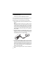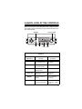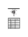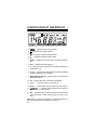
1
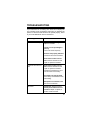
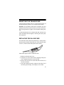
Cat. No. 19-1127
OWNER’S MANUAL
Please read before using this equipment.
HTX-252
2–Meter Amateur
FM Mobile Transceiver
FEATURES
Your RadioShack HTX-252 2–Meter FM Mobile Transceiver is a
compact and versatile transceiver, perfect either in your vehicle
or in your home. Vehicle cables and mounting hardware are supplied. Add an optional base-station antenna, cable, and a power
supply to make it your home transceiver. It is an all-around ideal
choice for your amateur communications needs.
Note: You must have a Technician Class or higher Amateur Radio Operator’s License and a call sign issued by the FCC to legally transmit using this transceiver. Transmitting without a license
carries heavy penalties. Getting a license is easier than ever. See
“Introduction to Amateur Radio” on Page 7 for more information.
Here are some of your transceiver’s features.
High (25 Watt) and Low (10 Watt) Power Settings — let you select the best power setting according to communication guidelines.
10 Memory Channels and 1 Call Channel — let you store up to
10 frequencies for quick access along with other settings such as
the repeater offset and the CTCSS tones.
Frequency Range of 144–148 MHz (TX) and 136–174 MHz
(RX) — provide flexibility and excellent wide coverage. You can
also extend the transmit frequency range to 142.00–
149.885MHz.
Channel Up/Down and 16-Key DTMF on the Mic — lets you
manually send DTMF (Dual-Tone, Multiple Frequency) tones to
quickly access DTMF-access repeaters, autopatches, or other
stations equipped with a DTMF page feature.
CTCSS (Continuous Tone Coded Squelch System) Subaudible
Tone — both encodes and decodes 38 subaudible tones to help
reduce interference from other nearby systems operating on the
same frequency.
©2000 Tandy Corporation.
All Rights Reserved.
RadioShack is a registered trademark used by Tandy Corporation.
2
Programmable Frequency Step — lets you set the frequency
step for tuning or scanning to 5, 10, 12.5, 15, 20, 25 kHz.
Signal Strength Indicator — a graduated bar shows the relative
strength of the received signal and transmitting signal.
Digital Phase-Locked Loop (PLL) Frequency Synthesizer —
provides highly accurate and stable tuning.
Built-In Automatic Modulation Control — ensures a constant
RF modulation level.
Repeater Offset — lets you select the appropriate offset value to
match a local repeater.
Scan — the transceiver scans the frequency range and the memory locations for transmissions.
Rotary Tuning — lets you reach a desired frequency quickly and
accurately.
External Speaker Jack — lets you connect an optional external
speaker for more flexible operation.
Illuminated Digital Display — clearly shows the frequency, the
functions, and the signal strength.
Key Lock — lets you lock the transceiver’s keys to prevent accidentally changing settings.
3
MANUAL CONVENTIONS
Some of your transceiver’s controls perform multiple functions.
The abbreviation or symbol for a function is printed on, or above
each multi-function button.
To activate certain transceiver features, you must press F (function) and then another button. Those key combination instructions are printed as the first button name, +, then the second
button name. For example, F+LOCK means press F then press
LOCK.
Control names are printed in small, bold, capital letters such as
CALL or VFO. Words, symbols, and numbers that appear on the
display are printed using a distinctive typeface, such as 146.94
or BUSY.
FCC INFORMATION
This device complies with Part 15 of the FCC Rules. Operation is
subject to the following two conditions: (1) This device may not
cause harmful interference, and (2) this device must accept any
interference received, including interference that may cause undesired operation.
4
CONTENTS
Introduction to Amateur Radio ............................................. 7
Preparation ............................................................................. 9
Attaching the Microphone Holder ..................................... 9
Mounting the Transceiver ................................................. 9
Connecting an Antenna ................................................... 11
Connecting the Microphone ............................................ 12
Using an External Speaker ............................................. 12
Connecting Power .......................................................... 13
Using the Transceiver as a Base Station ........................ 13
A Quick Look at the Controls ............................................. 15
A Quick Look at the Display ............................................... 18
Operation ..............................................................................
Turning the Transceiver On and Off ................................
Selecting Frequencies ....................................................
Receiving Transmissions ................................................
Transmitting ....................................................................
19
19
19
20
20
Understanding Repeaters ...................................................
Setting the Repeater Offset Frequency ..........................
Setting the Repeater Offset Direction .............................
Reversing the Transmit and Receive Frequencies .........
22
23
23
24
Memory Operation ...............................................................
Storing a Transmit/Receive Frequency ...........................
Recalling Memories ........................................................
Using the Calling-Frequency Memory ............................
25
25
25
26
Scanning Operation ............................................................. 27
Scanning for Active Frequencies .................................... 27
Scanning Standard Memory Locations ........................... 27
Continuous Tone Coded Squelch System Features ......... 28
Temporarily Opening Squelch ......................................... 28
Using DTMF Tones ............................................................... 30
5
Other Special features .........................................................
Using Priority Frequency Monitor ....................................
Using VFO Priority ...................................................
Using Memory Priority ..............................................
Changing the Transmit Frequency Range ......................
Selecting the Transmit Power Level ................................
Locking the Keypad .........................................................
Turning the Key Tone On and Off ....................................
Setting the Frequency Step .............................................
Reducing Interference .....................................................
31
31
31
31
32
32
32
33
33
33
Troubleshooting ................................................................... 35
Care and Maintenance ......................................................... 36
Resetting the Transceiver ............................................... 37
Replacing the In-Line Fuse ............................................. 37
Specifications ....................................................................... 38
6
INTRODUCTION TO AMATEUR RADIO
This transceiver is the perfect first radio for anyone entering the
exciting world of amateur radio, as well as a great additional
transceiver for the experienced amateur radio operator. This
transceiver opens a door for you to the world from almost anywhere! All you need is an Amateur Radio Operator’s License
(Technician Class or higher) issued by the Federal Communications Commission (FCC). If you do not have a license, it is easier
than ever to get one, and help from licensed operators is available. Here are a few tips to help you get started.
You can turn on your transceiver and scan the entire band to hear
what is going on; however, do not attempt to transmit until
you get your license. If you transmit without a license, you are
in violation of federal law that can lead to severe penalties. Note
that ham operators take the FCC rules very seriously and want
nothing to do with “bootleggers” — their term for people who operate without a license.
Find out if there is a ham radio club in your area. Most clubs welcome newcomers and are glad to help you get your license.
There are thousands of clubs across the country, so there is probably one in or near your community. The staff at your local RadioShack store often can help you locate a club.
If you do not hear anyone talking about a local club as you listen
to local transmissions, write to the American Radio Relay League
(ARRL) at the following address to find out how to contact a local
affiliate. The ARRL is the national organization representing amateur radio in the United States. The league has more than
150,000 members. Most are ham operators, or members in the
process of obtaining their license.
The American Radio Relay League
225 Main Street
Newington, CT 06111
http://www.arrl.org
7
Start studying for the license exams. Do not be intimidated by the
word “study,” because most people can go from knowing absolutely nothing about amateur radio to passing the Novice and
Technician written exams in less than a month.
The exams test your knowledge of basic radio regulations and elementary radio theory. Many clubs hold license classes which
can be a fun and easy way to learn about amateur radio. There
are good books, cassette tapes, computer programs, and many
other study aids available. Your local RadioShack store sells FCC
License Preparation study guides for amateur radio operator licenses. While you are no longer required to learn Morse code for
a Technician Class license, we encourage you to learn it anyway
so you can advance to higher levels of operating privileges.
There is no fee to take the Novice exam. As soon as you pass the
Novice exam, you can immediately take the Technician exam.
There is a small fee required for taking the Technician exam. All
license level tests are administered by a three-member Volunteer
Examiner Team. Contact the ARRL for a schedule of exam opportunities in your area.
The Technician Class license lets you use this transceiver to
communicate directly with other operators, and use repeaters for
distant communication.
Amateur radio is a great hobby that has enriched the lives of millions of people all over the world. The ARRL would be glad to hear
from you if you need more information or would like to join!
8
PREPARATION
ATTACHING THE
MICROPHONE HOLDER
Follow these steps to attach the
microphone holder to your vehicle.
1. Using the holder as a template, mark the position for the
mounting screw holes at the
desired location.
2. At each marked position, drill
a hole slightly smaller than the
supplied mounting screw.
Caution: Be careful not to drill
into anything behind the
mounting surface.
3. Use a Phillips screwdriver to attach the holder to the mounting location with the supplied small self-tapping sheet metal
screws and lock-washers.
MOUNTING THE TRANSCEIVER
The most common mounting location for this transceiver is under
a vehicle’s dashboard. However, if you plan to use the transceiver
as a base station, you can place it on a desk, shelf, or table (see
“Using the Transceiver as a Base Station” on Page 13).
If you are mounting the transceiver in a vehicle, choose a location where:
• you can easily reach the transceiver
• wires and cables are clear of the vehicle’s pedals or other
moving parts
• the transceiver is not directly in front of heating vents
• all wires and cables can reach their connection points
9
Caution: If you use the transceiver in a vehicle, mount it securely
to avoid damage to the transceiver or vehicle, or injury to anyone
in the vehicle during sudden starts or stops.
Follow these steps to mount the transceiver.
VO
L
OP
SQ
1. Using the mounting bracket as a template, mark the positions for the screw holes on the mounting surface,
2. In each marked location, drill a hole slightly smaller than the
supplied self-tapping screws.
Caution: Be care not to drill into objects behind the mounting surface.
3. Using a Phillips screwdriver, attach the mounting bracket to
the mounting surface with the supplied mounting screws
and flat washers.
4. Attach the transceiver to the mounting bracket using the
supplied rubber washers and mounting knobs.
10
CONNECTING AN ANTENNA
You must install an antenna before you can operate the transceiver. There are many different types of antennas suitable for
transceiver use. Each has its own benefits, Choose the one best
suited to your particular needs. Your local RadioShack store has
a wide selection from which to choose.
Note: If you are using the transceiver as a base station, see “Using the Transceiver as a Base Station” on Page 13.
When you install an antenna, keep in mind that, for the best performance, you should mount the antenna vertically as high as
possible on the vehicle and away from sources of electrical noise.
Once you choose an antenna, follow it’s mounting instructions.
Then route the cable to the transceiver and thread the cable onto
the ANT connector on the back of the transceiver.
Cautions:
• Avoid routing the cable next to sharp edges or moving
parts, which might damage the cable.
• Do not run the cable next to power cables or other radio
antenna cables.
• Do not run the cable through the engine compartment or
other areas that produce extreme heat.
To take advantage of your transceiver’s maximum range, adjust
the antenna’s standing wave ratio (SWR) using an SWR meter
(not supplied, available at your local RadioShack store). Follow
the instructions supplied with the SWR meter and antenna to adjust the antenna’s SWR. Values of 2.0:1 are generally acceptable, with readings of 1.5:1 or lower being more desirable.
11
CONNECTING THE MICROPHONE
1. Align the notch of the
microphone’s plug and
the microphone’s jack,
located on the left side of
the front panel. Then
insert the plug and turn
the metal ring clockwise
to secure the plug.
MHz
F
L
CALP
STE
N
SCA
PRI
Lock
FT
SHI
F ON
DTM
2. Slide the microphone onto the microphone holder.
To disconnect the microphone from the transceiver, turn the metal ring counterclockwise to loosen it.
Caution: Always disconnect the microphone by grasping its plug.
Never pull on the coiled microphone cable.
USING AN EXTERNAL SPEAKER
To hear your communications better in a noisy environment, you
can plug an optional, external speaker into the transceiver. The
speaker should have an impedance of 8-ohms and be able to
handle 3 to 10 watts of power. The speaker’s cable should have
a 1/8-inch (3.5-mm) plug.
To connect the speaker, insert the speaker cable’s plug into EXT.
SP on the back of the transceiver. This automatically disconnects
the built-in speaker.
12
CONNECTING POWER
Follow these steps to power the transceiver from your vehicle’s
battery.
1. Connect the supplied polarized
13.8V DC power connector to
the white power socket and
cable on the back of the transceiver. The plug and socket only
fit one way. If you can not easily
insert the plug, turn it over and
try again. Do not force it.
2. Connect the red wire (+) (with
the in-line fuse holder) to a point in your vehicle’s fuse block
that supplies power only when the ignition is in the ACC
(accessory) or ON position.
3. Connect the black wire (–) to a metal part of the vehicle’s
frame (chassis ground).
Caution: Do not connect the black wire to a non-metallic
(plastic) part, or to any part insulated from the vehicle’s
chassis by a non-metallic part.
USING THE TRANSCEIVER AS
A BASE STATION
Although this transceiver is designed for mobile use, you can also
use it as a base station with a DC power source. To use the transceiver as a base station, you need these items:
• a regulated power supply that supplies at least 7 amps at
12V DC
Caution: Most 12–13.8V DC power supplies operate from a
standard AC outlet. Before connecting your transceiver to
this type of power supply, read and follow the instructions
included with it.
13
• a base station antenna
• coaxial antenna cable and appropriate connectors
Your local RadioShack store carries a wide selection of all products needed to set up your transceiver as a base station.
Follow these steps to use the transceiver as a base station.
1. Mount the base station antenna as described in its owner’s
manual.
Warning: Use extreme caution when you install or remove
a base station antenna. If the antenna starts to fall, let it go!
It could contact overhead power lines. If the antenna
touches a power line, contact with the antenna, mast, cable,
or guy wires can cause electrocution and death. Call the
power company to remove the antenna. Do not attempt to
do so yourself!
2. Connect the antenna to the PL259 ANT connector on the
back of the transceiver. If the antenna’s plug does not match
the ANT jack on the back of the transceiver, contact your
local RadioShack store for a suitable adapter.
3. Connect the supplied polarized 13.8V DC power connector
to the white power socket and cable on the back of the
transceiver. The plug and socket only fit one way. If you can
not easily insert the plug, turn it over and try again. Do not
force it. Then connect the red power wire with the in-line
fuse (+) and the black power wire (–) to the appropriate terminals on your power supply.
4. Plug the power supply’s AC power cord into a standard AC
outlet.
14
A QUICK LOOK AT THE CONTROLS
Most of the controls on the transceiver have multiple functions.
The following charts should help you get a better idea of the function of each control.
OFF/VOL
SQ
Tuning Control
REV
VFO
MR
(T-SQ) (MS)
Base Unit
Use with the
F + Key to:
Key/Control
Use it to:
OFF/VOL
Turn the transceiver on/
off. Adjust the volume.
Reset the
transceiver
SQ
Set the squelch level to
block weak signals.
N/A
Reverse the
repeater offset.
N/A
VFO (T-SQ)
Set the transceiver to
VFO mode.
Set the tone
squelch.
MR (MS)
Recall a frequency in
memory.
Store a frequency
in memory.
Change the frequency
by the set STEP value.
Change the
frequency by 1 MHz
steps.
REV
Tuning Control
15
CALL
(STEP)
DN SCAN
(PRI)
LOCK
(SHIFT)
UP
F (MHz)
PTT
DTMF
Microphone
Use with the
F + Key to:
Key/Control
Use it to:
Push to
Talk (PTT)
Transmit by holding it
down. Press to store a
setting.
Change the transmitting
power to high or low.
UP
Increase the frequency by the selected
step value.
Increase the frequency
in 1 MHz steps.
DN
Decrease the frequency by the selected
step value.
Decrease the frequency
by 1 MHz steps.
F (MHz)
Temporarily open the
squelch.
N/A
CALL
(STEP)
Recall the calling frequency memory.
Set the frequency step.
16
Microphone
Key/Control
SCAN (PRI)
Use with the
F + Key to:
Use it to:
Start and stop
scanning.
Set the transceiver to
dual watch mode.
LOCK
(SHIFT)
Lock and unlock the
controls except PTT, F,
VOL, and SQ.
Set the repeater
offset.
AlphaNumeric
Keys
Enter numerical values and DTMF control
letters.
N/A
Switch to DTMF
control.
N/A
DTMF
17
A QUICK LOOK AT THE DISPLAY
1. FUNC — appears when F key is pressed.
2.
— indicates the keypad is locked.
3.
— indicates a negative repeater offset.
4.
— indicates a positive repeater offset.
5. SCAN — appears when the transceiver is scanning frequencies.
6. PRI — indicates a priority frequency.
7. T — appears when Tone Squelch (CTCSS) is enabled for
transmission only.
8. T-SQ — appears when Tone Squelch (CTCSS) is enabled
for both transmission and reception.
9. Alpha-Numeric Display — shows frequency and operation
feature information.
10. TX — appears when the transceiver is transmitting.
11. 0 to 9 — shows the memory channel in use.
12. BUSY — appears when the transceiver receives a signal.
13.
— indicates signal strength; the stronger the
signal, the more boxes appear.
14. ME — appears when the frequencies and other station data
are being stored or while scanning data in memory locations.
Note: When you reset the transceiver, all display elements appear. See “Resetting the Transceiver” on Page 37.
18
OPERATION
TURNING THE TRANSCEIVER
ON AND OFF
To turn on the transceiver, rotate VOL clockwise until it clicks. The
last used frequency and other settings appear (the default frequency is 142.50 MHz, with a frequency step of 5 kHz/.005 MHz).
To turn the transceiver off, rotate VOL counterclockwise until it
clicks.
SELECTING FREQUENCIES
To select a frequency in the VFO (variable frequency oscillator)
mode, use either UP or DN on the top of the microphone or the
tuning control.
Using either method lets you step up or down in increments which
you set using the Frequency Step option. (See “Setting the Frequency Step” on Page 33“).
Rotating the tuning control changes the frequency by the value of
the step you set. You might want to set your preference for the
step value before you make other settings. Repeatedly pressing
(or holding down) UP or DN also changes the frequency by the
step value. To change the frequency by 1MHz steps, press F so
FUNC appears. Then repeatedly press or hold down UP or DN.
The displayed frequency is typically shown to two significant decimal places. However, depending upon the selected frequency
step, you might see a smaller number displayed to the right of the
second place. For example, 142.5075 lets you see the complete
frequency in use if you select 12.5kHz as your frequency step.
19
RECEIVING TRANSMISSIONS
Follow these steps to receive standard transmissions.
1. With the transceiver on, rotate SQ counterclockwise until
you hear a hissing sound. Then slowly rotate SQ clockwise
just until the noise stops.
Notes:
• BUSY appears when the transceiver receives a standard
transmission or if the squelch is open.
• If the transceiver picks up unwanted and weak transmissions, rotate SQ clockwise to prevent the squelch from
opening for these transmissions. If you want to hear
weak transmissions, rotate SQ counterclockwise. When
you do this, you might hear hissing between transmissions.
2. Rotate the tuning control to select a frequency.
3. Set VOL to a comfortable listening level.
TRANSMITTING
There are two basic types of communication possible with this
transceiver: radio-direct-to-radio (simplex) or radio-to repeater-to
radio (duplex). Simplex operation uses the same frequency to
send and receive. Duplex operation uses one frequency to transmit and another to receive. For more information about duplex,
see “Understanding Repeaters” on Page 22.
Caution: It is illegal to transmit if you do not have at least a Technician Class license issued by the FCC.
Follow these steps to transmit.
1. Select the desired frequency using the tuning control or UP/
DN until you are within the transmit frequency range.
20
2. Hold the microphone about 3 inches from your mouth.
3. Hold down the ribbed transmit button on the side of the
microphone, then speak slowly and clearly into the microphone. TX appears while you transmit, and signal strength
bars appear on the bottom to indicate the relative transmitting signal output.
Note: If you try to transmit outside the transmit frequency
range, E appears instead of TX to indicate you are outside the transmitting range.
4. Release the transmit button when you finish transmitting.
21
UNDERSTANDING REPEATERS
Operating through a repeater, where you transmit on one frequency and receive on another, is called duplex operation. Operating direct to another station, where you transmit and receive on
the same frequency, is called simplex operation.
A repeater is a station that receives a signal on one frequency
(the input frequency) and then retransmits that signal on a different frequency (the output frequency). Repeater antennas are typically located at the tops of tall buildings or on antenna towers, so
a relatively low-power signal can reach the repeater. The repeater retransmits the signal at a higher power. This gives your transceiver the ability to communicate over a much greater range.
To use a repeater, you must know the repeater’s input and output
frequencies. Repeaters are usually identified by their output frequency. For example, a repeater that has an output frequency of
146.94 is referred to as “the 146.94 repeater.” To determine the
input frequency, you must know the frequency offset (typically
600 kHz for the 2-meter band) and the offset direction (+ if you
add 600 kHz to the output, or – if you subtract 600 kHz from the
output).
Whether the offset is positive or negative depends on:
• which part of the band the repeater operates on
• local convention
• proximity of repeaters using the same two frequencies
To determine the offset and the direction, obtain a copy of The
ARRL Repeater Handbook (available at your local RadioShack
store or directly from the ARRL). That book lists the locations of
repeaters as well as their frequency and offset information.
above the displayed frequency indicates a positive offset,
A
while a
above the frequency indicates a negative offset. If neither
nor appears, the transceiver is set for simplex operation.
22
SETTING THE REPEATER OFFSET
FREQUENCY
Note: This setting affects only the VFO mode. If you saved a repeater offset in a memory, that setting is not affected.
1. Press F+SHIFT (LOCK). The offset frequency and
appear.
2. While the offset frequency appears, rotate the tuning control
or repeatedly press UP or DN until the desired offset
appears. The transceiver’s default repeater offset is 600
kHz, which appears as 0.60 (MHz). You can select a
value from 100 kKz to 8.000 MHz.
3. Press PTT to store the setting or wait 5 seconds. The
selected value is stored and the operating frequency
appears.
SETTING THE REPEATER OFFSET
DIRECTION
1. Set an offset frequency.
2. Repeatedly press F + SHIFT (LOCK) to change the current
offset direction ( above, below, or neither for simplex or
non-repeater operation).
3. Press PTT to store the setting or wait 5-seconds. The
selected value is stored and the operating frequency
appears.
23
REVERSING THE TRANSMIT AND
RECEIVE FREQUENCIES
To swap the input and output frequencies, press REV. For example, if you have set the transceiver to repeater operation on
146.94 MHz with a positive offset of 600 kHz, the transceiver
would normally receive on 146.94 MHz and transmit on 147.54
MHz. After you press REV, the transceiver is set to receive on
147.54 MHz and transmit on 146.94 MHz.
This feature is useful if you want to determine whether you are
close enough to another station to communicate on a simplex frequency. While the other station is transmitting, reverse the frequencies. If you can still hear the other station, you are hearing
their signal directly and you do not need to use the repeater.
24
MEMORY OPERATION
Your transceiver has 10 standard memory locations that you can
use to store frequencies for quick access. You can also store other settings for each memory location, such as the repeater offset
and the CTCSS tones.
STORING A TRANSMIT/RECEIVE
FREQUENCY
1. Select the frequency you want to store by using the tuning
control or UP/DN.
2. If desired, select an offset frequency, offset direction, and
CTCSS frequency for the selected frequency (see “Setting
the Repeater Offset Frequency” on Page 23 and “Continuous Tone Coded Squelch System Features” on Page 28).
3. Press F+MS. A memory location appears and flashes if
empty. To select a different memory location, repeatedly
press UP/DN or rotate the tuning control.
4. Press MR. The transceiver stores the selected settings in
the memory location.
5. Press VFO to exit the memory mode.
RECALLING MEMORIES
1. Press MR so a memory location number appears.
2. Press UP or DN or rotate the tuning control to select the
desired memory location.
3. Press VFO to return to the VFO mode.
25
USING THE CALLING-FREQUENCY
MEMORY
The calling-frequency memory location lets you quickly jump to a
specific programmed frequency at any time. The default calling
frequency is 146.52 MHz. You can store a different frequency into
memory as well as other settings associated with that frequency,
such as the repeater offset and CTCSS tone.
1. Select the desired calling frequency using UP/DN or the tuning control.
2. Press F+MR (MS). A memory location and ME appear.
3. Rotate the tuning control or repeatedly press UP or DN until
C appears in the memory location area on the display.
4. Press MR (MS). C flashes.
5. Press MR (MS) again to store the selected frequency.
6. Press VFO (T-SQ) to return to the VFO mode.
To enable the calling frequency, press CALL at any time. The
transceiver immediately tunes to that frequency with the settings
you programmed. To exit the calling frequency mode, press VFO
(T-SQ).
26
SCANNING OPERATION
SCANNING FOR ACTIVE FREQUENCIES
1. To search for activity on a frequency, press SCAN (PRI).
SCAN appears. The transceiver begins to scan up or down
the full frequency range. The transceiver stops on each
active frequency for 5 seconds if squelch is on. If squelch is
off, the transceiver stops on each location for about 1 second.
2. To change the scanning direction, press UP or DN.
3. To stop on a frequency or to stop scanning completely,
press SCAN again.
SCANNING STANDARD MEMORY
LOCATIONS
1. Press MS (MR) then SCAN. The transceiver scans all memory locations except empty locations.
2. To change the scanning direction, press UP or DN.
3. To stop scanning, press SCAN again.
27
CONTINUOUS TONE CODED
SQUELCH SYSTEM FEATURES
Your transceiver can transmit and receive a low-level, selectable
subaudible tone at the same time as it transmits (TX) or receives
(RX) a regular signal. This special tone lets you listen only to other transceivers set to the same tone frequency when you use the
transceiver in simplex operation. It also lets you match your transceiver to the subaudible tone frequency used by a local repeater.
To enable the TX and RX tones for the transceiver, follow these
steps.
1. Press F+T-SQ. The current tone setting and T appear. (T
indicates that only the TX tone is enabled.)
2. Rotate the tuning control or repeatedly press UP or DN to
select a tone frequency from the list on Page 28. About 5
seconds after your last change, the display exits the tone
setting mode, stores your tone selection, and the current
operating frequency appears again.
3. To enable both the TX and RX tones, repeatedly press F+TSQ until T-SQ appears. To disable CTCSS operation,
repeatedly press F+T-SQ until T and T-SQ disappear.
4. Press PTT to store all the settings.
TEMPORARILY OPENING SQUELCH
If you use the Tone Squelch (CTCSS) feature, you might not hear
a transmission on the current frequency. To temporarily open the
squelch so you can hear all transmissions on the frequency, hold
down F. To resume normal operation, release F.
28
Subaudible Tone Frequencies (Hz)
67.0
107.2
167.9
71.9
110.9
173.8
74.4
114.8
179.9
77.0
118.8
186.2
79.7
123.0
192.8
82.5
127.3
203.5
85.4
131.8
210.7
88.5
136.5
218.1
91.5
141.3
225.7
94.8
146.2
233.6
97.4
151.4
241.8
100.0
156.7
250.3
103.5
162.2
29
USING DTMF TONES
DTMF (Dual-Tone, Multiple Frequency) is another term for touchtones (the tones a telephone produces when you press a digit).
This standard set of tones is used by many different amateur
transceiver systems for accessing programmable features and
dialing through autopatches to a standard telephone.
Your transceiver produces all 16 standard DTMF tones (0–9,*, #,
A, B, C, and D).
Follow these steps to use the DTMF feature.
1. Set DTMF on the bottom of the microphone to ON.
2. Enter the DTMF sequence using the alphanumeric keys.
3. After you complete your transmission, set DTMF to the left
position to turn off the feature.
30
OTHER SPECIAL FEATURES
USING PRIORITY FREQUENCY MONITOR
You can designate one frequency as primary (in either VFO or
memory mode) and another frequency as secondary (VFO only).
Once you do that, the transceiver tunes the primary frequency or
memory location for 5 seconds. Then it checks the secondary frequency for 1/2 second. If the transceiver finds a signal on the secondary frequency, it automatically remains there for 5 seconds
before returning to the primary frequency.
Using VFO Priority
1. Select the desired secondary frequency using the tuning
control or UP/DN.
2. Press F+PRI (SCAN)
3. Select the primary frequency using the tuning control or UP/
DN. The transceiver starts to monitor both selected frequencies.
4. To disable priority monitor, press F+PRI (SCAN) again.
Using Memory Priority
1. Select the desired secondary VFO frequency using the tuning control or UP/DN.
2. Press F+PRI (SCAN)
3. Press MR (MS) then select the desired memory location for
your primary frequency. The transceiver starts to monitor
both selected frequencies.
4. To disable priority monitor, press F+PRI (SCAN) again.
31
CHANGING THE TRANSMIT FREQUENCY
RANGE
You can change the standard transmit frequency range from
144–148 MHz to an extended range of 142.000–149.885 MHz.
To set the transceiver to its extended range, turn it off. Then while
holding down F and LOCK, turn on the transceiver.
To return to the standard frequency range, repeat the above procedure.
SELECTING THE TRANSMIT POWER
LEVEL
You can select either of two transmitting power levels: high (25
watts) for normal operation or low (10 watts). Choose the lower
level to reduce the possibility of overloading nearby receivers.
Choose the higher level when conditions warrant maximum
transmitting power. To switch levels, press F+PTT. If low is selected, LOW appears. If high is selected, LOW disappears.
LOCKING THE KEYPAD
To lock the transceiver’s keypad so you do not accidentally
change a setting, press LOCK (SHIFT).
appears. This locks all
controls except PTT, F, VOL, SQ, and LOCK.
To unlock the keypad, press LOCK again.
32
TURNING THE KEY TONE ON AND OFF
The transceiver is preset to sound a beep each time you press a
key. To turn off the beep, hold down the PTT button while you turn
on the transceiver’s power. To restore the key tone, repeat the
procedure.
SETTING THE FREQUENCY STEP
To change the frequency increment used during scanning and
stepping to a frequency, press F+STEP (CALL). The current frequency step appears. Then repeatedly press UP or DN or rotate
the tuning control to change the setting. The default is 5 kHz. You
can change the frequency step to 5 kHz, 10 kHz, 12.5 kHz, 15
kHz, 20 kHz, or 25 kHz.
REDUCING INTERFERENCE
Because your transceiver is exceptionally quiet, any noise you
hear probably originates from a source within your vehicle such
as the alternator, the spark plugs, or unshielded wires.
To solve the problem, you must locate the noise’s source. You
can determine the noise’s source by first turning off the engine
and operating the transceiver with your vehicle’s ignition set to
ACC. If the noise decreases or disappears completely, the problem is with your vehicle’s ignition or associated wiring.
Here are a few suggestions to help you reduce or eliminate such
noise:
• Make all of the transceiver’s power and antenna wires as
short and as direct as possible.
• Route the power wires away from the antenna wires.
• Be sure the chassis ground connection is secure.
33
• Replace old ignition wires with new, high-voltage, noise suppression wires.
• Install noise suppressors on your spark plugs, or install new
spark plugs that have built-in noise suppressors.
• If problems persist, check to ensure your alternator and
electrical system are operating correctly. You can reduce
any noise by using bypass capacitors at the various output
voltage points.
Your local RadioShack store carries a wide selection of capacitors and other appropriate noise reduction components.
34
TROUBLESHOOTING
If your transceiver is not working as it should and it displays an
error message, these suggestions might help you eliminate the
problem. If the transceiver still does not operate properly, take it
to your local RadioShack store for assistance.
Symptom
Problems with reception
Possible Cause and Solution
Squelch setting too high.
Adjust as needed.
Tuned to a non-operating frequency.
Tune to an active frequency.
Antenna not properly attached.
Check and reconnect if needed.
Poor antenna cable connections. Check connections and
repair or replace as needed.
Problems with transmission
Poor antenna cable connections. Check connections and
repair or replace as needed.
Check all connections for corrosion and clean if necessary.
PTT button not fully pressed.
Press firmly and hold down when
transmitting.
Microphone connection loose.
Secure the connection.
No Power
Check fuse. Replace if blown.
Check power cables and connections. Repair or replace if
broken or disconnected.
35
CARE AND MAINTENANCE
Your RadioShack 2-Meter FM Mobile Amateur Transceiver is
an example of superior design and craftsmanship. The following suggestions will help you care for your transceiver so you
can enjoy it for years.
Keep the transceiver dry. If it gets wet, wipe it dry
immediately. Liquids might contain minerals that
can corrode the electronic circuits.
Use and store the transceiver only in normal temperature environments. Temperature extremes
can shorten the life of electronic devices, damage batteries, and distort or melt plastic parts.
Keep the transceiver away from dust and dirt,
which can cause premature wear of parts.
Handle the transceiver gently and carefully.
Dropping it can damage circuit boards and cases
and can cause the transceiver to work improperly.
Wipe the transceiver with a damp cloth occasionally to keep it looking new. Do not use harsh
chemicals, cleaning solvents, or strong detergents to clean the transceiver.
Modifying or tampering with the transceiver’s internal components can cause a malfunction and might invalidate its warranty and void your FCC authorization to operate it. If your
transceiver is not performing as it should, take it to your local
RadioShack store for assistance.
36
RESETTING THE TRANSCEIVER
If the transceiver’s display locks up or the transceiver does not
work properly after you turn it on, you might need to reset it.
Important: This procedure clears all the information you have
programmed into the transceiver. Before you reset the transceiver, try turning it off then on again to see if it begins working properly.
To reset the transceiver, turn it off then hold down F and turn it on
again. All display elements appear, confirming the reset operation. Release F.
REPLACING THE IN-LINE FUSE
The transceiver (and vehicle) are protected by a 10-amp fuse in
the transceiver’s positive (red) power wire. If the transceiver does
not turn on, check the fuse and replace it to be certain.
Follow these steps to check or replace the fuse,
1. Make sure the transceiver is off.
2. Snap open the in-line fuse holder by applying thumb pressure in opposite directions on the seam lock.
3. Remove the fuse from the holder and slide the fuse out of
the end connectors.
4. If the fuse’s filament is blown, replace the fuse with one of
the same type and rating. Then snap the cover closed.
37
SPECIFICATIONS
GENERAL
Frequency:
TX ................................................ 144.000–148.000 MHz
Extended TX Range .................... 142.000–149.885 MHz
RX ................................................ 136.000–174.000 MHz
Frequency Control .......................... Digital PLL Synthesizer
Display Type.................................................................. LCD
Operating Temperature ................................... –4° to 122°F
(–22.5° to 49.5°C)
Power Requirements ............................................ 13.8V DC
(12–16V DC, negative ground)
Antenna ................................... 50-ohm (coaxial connector)
Dimensions (HWD) ........................ 11/4 × 53/25 × 51/2 inches
(32 × 130 × 140 mm)
Weight ............................................................................ 1.54 lb.
(0.7 kg)
RECEIVER
Sensitivity ......................................... 0.22 µV for 10 dB S/N
Overload Audio Fidelity @ 6dB Down ............. 450–2100 Hz
Adjacent Channel Selectivity ..................................... 60 dB
Spurious and Image Rejection ........................... 60 dB Min.
Maximum Audio Output Power...... 2.5 watts @ 8-Ohm load
Squelch Tight Range .................................... 0.5 m to 1 mV
Battery Drain:
No Signal ............................................................ 300 mA
Maximum Output ................................................ 600 mA
38
TRANSMITTER
Max Power Output:
High .................................................................. 25 watts
Low .................................................................... 10 watts
Spurious Emission .................................. Better than –65dB
Deviation ................................................................. ± 5 kHz
Battery Drain:
High ............................................................................ 5A
Low .............................................................................. 3A
Specifications are typical; individual units might vary. Specifications are subject to change and improvement without notice.
39
Limited One-Year Warranty
This product is warranted by RadioShack against manufacturing defects in
material and workmanship under normal use for one (1) year from the date
of purchase from RadioShack company-owned stores and authorized RadioShack franchisees and dealers. EXCEPT AS PROVIDED HEREIN, RadioShack MAKES NO EXPRESS WARRANTIES AND ANY IMPLIED
WARRANTIES, INCLUDING THOSE OF MERCHANTABILITY AND FITNESS FOR A PARTICULAR PURPOSE, ARE LIMITED IN DURATION TO
THE DURATION OF THE WRITTEN LIMITED WARRANTIES CONTAINED HEREIN. EXCEPT AS PROVIDED HEREIN, RadioShack SHALL
HAVE NO LIABILITY OR RESPONSIBILITY TO CUSTOMER OR ANY
OTHER PERSON OR ENTITY WITH RESPECT TO ANY LIABILITY, LOSS
OR DAMAGE CAUSED DIRECTLY OR INDIRECTLY BY USE OR PERFORMANCE OF THE PRODUCT OR ARISING OUT OF ANY BREACH
OF THIS WARRANTY, INCLUDING, BUT NOT LIMITED TO, ANY DAMAGES RESULTING FROM INCONVENIENCE, LOSS OF TIME, DATA,
PROPERTY, REVENUE, OR PROFIT OR ANY INDIRECT, SPECIAL, INCIDENTAL, OR CONSEQUENTIAL DAMAGES, EVEN IF RadioShack
HAS BEEN ADVISED OF THE POSSIBILITY OF SUCH DAMAGES.
Some states do not allow limitations on how long an implied warranty lasts
or the exclusion or limitation of incidental or consequential damages, so the
above limitations or exclusions may not apply to you.
In the event of a product defect during the warranty period, take the product
and the RadioShack sales receipt as proof of purchase date to any RadioShack store. RadioShack will, at its option, unless otherwise provided by
law: (a) correct the defect by product repair without charge for parts and labor; (b) replace the product with one of the same or similar design; or (c) refund the purchase price. All replaced parts and products, and products on
which a refund is made, become the property of RadioShack. New or reconditioned parts and products may be used in the performance of warranty service. Repaired or replaced parts and products are warranted for
the remainder of the original warranty period. You will be charged for repair
or replacement of the product made after the expiration of the warranty period.
This warranty does not cover: (a) damage or failure caused by or attributable to acts of God, abuse, accident, misuse, improper or abnormal usage,
failure to follow instructions, improper installation or maintenance, alteration, lightning or other incidence of excess voltage or current; (b) any repairs other than those provided by a RadioShack Authorized Service
Facility; (c) consumables such as fuses or batteries; (d) cosmetic damage;
(e) transportation, shipping or insurance costs; or (f) costs of product removal, installation, set-up service adjustment or reinstallation.
This warranty gives you specific legal rights, and you may also have other
rights which vary from state to state.
RadioShack Customer Relations,200 Taylor Street,
6th Floor, Fort Worth, TX 76102
We Service What We Sell
12/99
RadioShack
A Division of Tandy Corporation
Fort Worth, Texas 76102
02A00
Printed in Korea