1
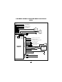
3
M AY, 1 9 9 9
CHANNEL SYSTEMS
INSTALLATION MANUAL
INFORMATION.)
Before Installing:
1. Read the INSTRUCTIONS!
8. REMOVE DOME LIGHT FUSE TO
PREVENT BATTERY DRAIN.
2. USE A DIGITAL OR ANALOG
VOLT/OHM METER
3. BEFORE MOUNTING THE PRODUCT CHECK THE POSSIBLE LOCATIONS FOR THE SIREN, LED, AND
MODULE BEFORE YOU PERMANENTLY
INSTALL THEM.
Timing Information
Automatic reset time: 45 seconds,
Panic output reset time: 45 seconds,
Arming time (when all inputs are monitored): 10 seconds-active arm, passive 30
+10 seconds (40 total)
Door Lock output time: .75 seconds
or 3 seconds (programmable via dip
switch #1)
2nd Channel output: Pressing button 2
for 3 seconds provides output for as long
as button is pressed.
3rd Channel output: Pressing both
buttons 1 & 2 (3rd button on a 3-button
remote) simultaneously provides continuous output on 3rd channel as long as
both buttons are pressed.
Armed output: Orange wire will pro-
4. PROTECT THE VEHICLE BY USING
FENDER COVERS.
5. ROLL DOWN THE DRIVER’S WINDOW BEFORE STARTING THE INSTALLATION.
6. ALWAYS LOOK BEFORE DRILLING.
MAKE SURE YOU WILL NOT CAUSE
DAMAGE TO VEHICLE HOSES, ELECTRICAL LOOMS OR PHYSICAL DAMAGE TO VEHICLE.
7. PROGRAM THE DIP SWITCH ON
THE MODULE FIRST(SEE DIP SWITCH
1
Input Zone Out Feature:
If a door input, shock or sensor input
remains on for 4 consecutive cycles (45
seconds) that input will be ignored. If the
input returns to a non-triggered state for
30 seconds it will be monitored by the
system again.
duce a grounded output when system is
armed.
Flashing Parking Light Output:
Armed: 1 second pulsed, Disarmed: 2-one
second pulses-, then output will latch on
for 30 seconds, or until ignition is turned
on, or system rearms. System triggered: 1
second pulse on, 1 second off, repeated
for 45 seconds.
Dome Light Output: Output is identical to Flashing Parking Light Output.
PROGRAMMING FEATURES
3 CHANNEL SOFTWARE
UPDATE
Super Selective
Receiver Board:
The new receiver design allows for a
much narrower band width reception. It
rejects RF interference that causes inconsistent range in similar type products and
improves the range of transmission
between remote and receiver. Average
minimum range is 100’ although it is common to get between 150’-300’. Our
extended range model with windshield
mounted receiver allows for up to 500’ of
range.
All 3 channel platforms have been updated
with new programmable features!
Features that can be programmed are the
following:
1. Parking lights can be programmed to
not stay on after disarm (car locator function).
2. Double unlock pulses can be added.
3.The 3rd channel can be programmed to
give a pulsing output when alarm is triggered to be connected to the car horn.
4. 2nd channel Auto disarm feature, when
3 Channel Programmable Features:
Feature #
Button One=ON
Feature #
Button Two=OFF
(1) Car Locator feature ON (parking
(1) Car Locator feature OFF
lights stay on 30 sec. after disarm).
(2) Single unlock pulse
(2) Double unlock pulse
(3) Red/White wire is 3rd. Channel output (3) Red/White wire is (-) horn output
(4) Channel# 2 normal operation
(4) Auto disarm when Ch.# 2 used
Default features are all ON.To change all features to default position enter program mode as
above and press both buttons 1&2 together until siren chirps.
2
4. Press button one or two on the transmitter to change to the desired program
to the feature.
Example: Programming the 3rd channel to
horn output.
1. Ignition Key On,
2. Press Valet switch 5 times
3. Siren will give long chirp,
4. Next, press Valet switch 3 times, siren will
chirp after each time you press the switch
5. Press button #2 on transmitter
6.Turn ignition key off.The red/white wire on
the main harness now is programmed to be
the 2nd channel is used for opening the
trunk or hatch, the alarm (if armed) will
automatically disarm.
To program these specific features
follow the procedure below:
1.Turn ignition key to the ON position
2. Press the valet switch 5 times (siren will
give long chirp).
3.Then select the program that you wish
to change and press the valet switch the
same number of times.The siren will
chirp each time you press the switch.
Summary of Inputs and outputs:
Inputs:
Outputs
1 Sensor port-4 wire (w/warn away)
Siren output: 3 amp Max - positive
1 Sensor port -3 wire
Flashing lights: relayed - 15 amp Max
Negative door trigger
Starter Interrupt: relayed:40 amp (N.C.)
1 Negative hood/trunk trigger
Dome Light: relayed- 15 amp Max
1 Positive door trigger
Door lock/unlock : 500 ma -negative
Door lock/unlock: relayed* 15 amp max
2 nd Channel: 500 ma- negative
3rd Channel: 500 ma - negative
*Module with door lock relays on board
Armed Output: 250 ma - negative
Dip Switch Programmable Features:
Switch #1= Lock/Unlock Pulse Time:
ON= .75 seconds
Switch #2= Ignition Triggered Door Locks: ON= Feature On
Switch #3= Passive Door Locks:
ON= Feature On
Switch #4= Passive or Active Arming:
ON= Passive Arm
3
OFF= 3 seconds
OFF= Feature OFF
OFF= Feature OFF
OFF= Active Arm
short chirp, confirming that the shock
sensor and auxiliary sensor input will not
be monitored. Once you disarm and
rearm, the hood and doors will be monitored normally.
Using the temporary remote sensor and
trigger bypass to diagnose falsing problems
will allow you to easily find the defective
input. (Have the customer turn one or the
other off, and see if falsing still occurs).
NOTE: You may not turn off both sensor
or trigger inputs at the same time.
Silent Arm/Disarm: If you wish to arm
or disarm you alarm, but do not want the
siren to chirp:
1. Press Button #2 momentarily.
This will temporarily delete the arm or
disarm chirps. Chirp can only be heard if
standing right next to the vehicle. Chirps
will be muted for one complete cycle
(arm/disarm).
a horn output when the alarm is triggered or
panicked.
Chirp Delete: If you would like to turn
off the arm/disarm chirps:
1. System disarmed,
2. Turn ignition to the on position,
3. Press and hold Button #2 until you
hear a double chirp. Arm/Disarm chirps
will remain turned off until above procedure is repeated.When Arm/Disarm
chirps are turned back on you will hear 2
double chirps.
Temporary Remote Trigger Bypass: If
you wish to have the system ignore all
inputs (door, trunk and shock or auxiliary
sensor), but wish to have the starter disable feature engaged:
1. Press Button #1, you will hear a normal arming chirp, (as long as arming
chirps are on).
2. Within 5 seconds press Button #2, you
will hear a second short chirp, confirming
that all inputs will not be monitored.
Once you disarm and rearm, the hood
and doors will be monitored normally.
Temporary Remote Sensor Bypass: If
you wish to have the system ignore the
shock and auxiliary sensor inputs
(Customer is leaving pet or children in
vehicle but wishes to monitor doors and
hood or trunk)
1. Press Button #1, you will hear a normal arming chirp, (as long as arming
chirps are on).
2. Within 5 seconds press Button #1 & 2
simultaneously.You will hear a second
Using Valet/Override Switch
Valet Mode: If the system is programmed to passively arm (dip switch #4
on), and you wish to keep system from
arming but wish to retain keyless entry
features:
1. Disarm the system.
2. Turn ignition to on.
3. Press and hold valet/override switch
for approximately 3 seconds.
4. LED will turn on solid, Siren will chirp
once.
To exit Valet mode: Repeat the procedure, LED will turn off momentarily and
4
programming two remotes with the same
code, the system will acknowledge only
the first remote. Even though both
remotes will operate the system.
the siren will chirp twice.
Emergency Override: If you lose your
remote or it becomes inoperable, and
system is armed:
1. Open door and enter vehicle (Siren
will sound, lights will flash).
2. Turn ignition key to on.
3. Press the override switch.
4. System will disarm, and automatically
enter Valet mode, regardless of whether
system is programmed to passively or
actively arm.
Code Learning Mode: If you wish to
“teach” the system different remote controls:
1. Make sure system is disarmed or in
valet mode,
2. Turn ignition switch on 3 times within
5 seconds and leave in the on position
(ON, OFF, ON , OFF, and ON), you will
hear one chirp from the siren, LED will
flash one time,
3. Within 5 seconds press and hold
valet/override switch for approximately 5
seconds, you will hear a series of chirps
and LED will turn on solid,
4. Release the valet switch, and within 5
seconds you must press button 1 of all
transmitters that you desire to operate
the system.You will hear a chirp after the
system has learned each remote control.
The system will hold 3 different codes in
memory.
NOTE: Once you enter the code learning mode, the system will throw out any
previous programmed remotes. If you are
INSTALLATION
INSTRUCTIONS:
1. Mount the module and program dip switch functions
(see page 3):
Look for a suitable mounting location
under the dash or inside the vehicle that
will be difficult for a potential thief to
locate the module, but allow for a convenient installation position.
Keep the antenna wire away from wire
looms, computer modules and metallic
objects for better range.Wire tie or
screw the module securely.
2. Mount the Siren:
Locate a suitable place under the hood,
away from hot and moving engine parts
such as manifolds, turbo chargers, fan
belts, etc. Secure siren by screwing bracket to a solid location under the hood.
Make sure that there is no outside access
to both siren and wire from underneath
the vehicle or through the grill.
Point the siren down so that water may
not accumulate inside the siren bell.
Ground the black wire of the siren to a
solid ground; preferably, use a star washer
and ring terminal.
5
den location, but that can still be found by
the customer for programming and emergency override situations. Run the 2 pin
blue connector and wire harness to the
module and plug into the matching blue 2
pin connector on the module.
When running wires inside the vehicle to
the module location, use either tape or
split loom tubing to cover and route the
red wire to the firewall. Always use either
existing grommets or if a new hole is
needed to be drilled protect the wire
from chaffing by installing a proper size
grommet.
6. Connect Starter
Disable Relay:
Using a volt/ohm meter locate the starter
wire (normally a heavier gauge wire) off
of the ignition switch.The meter will read
12V+ only during cranking.When the
starter wire has been located, cut the
wire, the vehicle should not be able to
start now. Cut the brown starter disable
wire (with the two female connectors).
Connect one side to the vehicle’s starter
wire, then plug to either .25 male spade
lugs on the module.There is no polarity.
Connect the other brown wire to the
other starter wire off of the ignition
switch. Plug the brown wire to the other
.25 male spade lug on the module.The
car should now start.
3. Mount the shock sensor:
Mount the dual stage shock sensor using
a wire tie to the steering column, or thick
wire harness, or even a dash brace. Plug
the harness into the shock sensor, then
plug the other end into the 4 pin white
connector on the module. Make sure that
the adjustment screw is accessible for
later testing and adjustment. Do Not
mount sensor under the hood!
4. Install the Status
Indicator (LED):
Locate a suitable place for the status indicator (LED), drill the appropriate size
hole (7/16”). Make sure there is enough
depth for the LED to fit all the way in,
and can be easily seen from outside the
vehicle. Carefully run the LED and 2 pin
red connector and wire harness to the
module and plug into the matching red
two pin connector on the module. Push
the LED into the hole, it should fit snugly.
7. Connect the Illuminated
Entry Output: Black/White
wires on main harness
If the vehicle has a negative door switch,
connect one of the two black/white wires
from the main harness to ground.
Connect the second black/white wire to
the green wire, also from the main harness (negative door input). If the vehicle
5. Install the Valet/
Override Switch:
Mount the valet/override switch in a hid-
6
11. Connect Hood/ Trunk
switch input:Blue wire on main
harness
Connect the blue wire to either or both
hood and trunk switches.They must provide a ground output when the trunk or
hood are opened.
has a positive door switch, connect one
of the black/white wires to a constant
12V+ source and the other black/white
wire to the violet wire also from the main
harness (positive door input).
8. Connect Optional Armed
Output: Orange wire on the
main harness
This wire provides a 250 ma ground output when the alarm is armed. It can be
used to control optional modules. (i.e.
window control modules, or used with
another relay to interrupt another circuitsuch as fuel pump, ignition).
12. Connect Positive Door input:
Violet wire on main harness
Connect the violet wire from the module
to the wire that shows 12V+ when all of
the doors are opened.Verify with
volt/ohm meter. Make sure that all doors
when opened separately make the target
wire provide a 12V+ output.
9. Connect 2nd channel output: Gray wire on main harness
This output is 500ma, and drives a relay
to open the electric trunk or hatch
release. (See diagram section).
NOTE: This output will work with the
ignition on or off. Press Button # 2 and
hold for 3 seconds.You will receive output on the gray wire as long as you hold
Button # 2.
13. Connect Siren Output:
Brown wire on main harness
Connect the brown wire on the main
harness to the red wire from the siren.
14. Connect the Flashing
Parking Light Output: White
wire main harness.
Using a volt/ohm meter, locate the wire
(usually on the head light switch) that
shows 12V+ when only the parking lights
are switched on. European vehicles may
require an additional relay if they have
separate wires that switch on the left and
right side parking lights.
This relayed output has a maximum of 15
amps. Do not hook to head lights. (See
diagram section).
10. Connect Negative door
input: Green wire on main harness
Connect the green wire from the module
to the wire that shows ground when all
of the doors are opened.Verify with a
volt/ohm meter. Make sure that all doors
when opened separately make the target
wire provide a ground output.
7
18. Connect optional third
channel output: White/Red
wire on main harness
Connect the white/red wire on main harness to an optional relay or accessory
module to control via the 3rd channel.
Ideal for window roll up or remote start.
To use this feature press both buttons
1&2 on 2 button remote control, or
Button # 3 on 3 button remote. NOTE:
This output will work with the ignition on
or off and will provide output on the
white/red wire as long as you hold proper
transmitter buttons.
15. Connect 12V+ Power Input
: Red wire on main harness
Connect the red fused wire on the main
harness to a constant 12V+ source.
This source wire should be at least 20
amp supply.There usually is a main constant power wire on the ignition switch.
Use volt/ohm meter to verify.
16. Connect the 12V+ ignition
input: Yellow wire on main
harness
Connect the yellow wire on the main
harness to a main ignition wire.This can
be also found in the main ignition switch
wire harness.Your volt/ohm meter will
read 12V+ when key is turned on.
Make sure that this ignition wire has
12V+ on even during the starting process
of the vehicle. It is important that the
voltage does not drop when the car is
starting.
Some vehicles have ignition wires that
remain or slowly drop to 0 volts.Verify
that when the ignition is shut off that the
voltage drops to 0 Volts immediately. If
the yellow wire has voltage on it after the
key is turned off, it will keep the alarm
from arming via the remote.
19. Connect the door lock
wires: Blue and Green on 5 pin
harness.
For Module without on board door
lock/unlock relays:
The blue wire provides a 500 ma negative
pulsed output for unlock, this output is
designed to drive a relay (See diagram
section).
The green wire provides a 500 ma negative pulsed output for lock, this output is
designed to drive a relay (See diagram
section).
The Violet, Brown and White wires do
not need to be connected on the 3 channel module without on board relays for
door locks.
For Module with on board door
lock/unlock relays:
Connect the violet wire to the proper
polarity (negative or positive).
17. Connect Ground Input:
Black wire on main harness
Locate a good solid chassis ground and
connect to the black wire on main harness.Verify the ground with your
volt/ohm meter.
8
that they arm and disarm all the way
around the vehicle; adjust the module
antenna location if necessary.
Using the remote and valet switch, check
for the user features: chirp mute, service
mode, valet mode, temporary trigger and
sensor bypass, and chirp delete.
Tie up wire harness, and replace any
under dash panels.
Deliver the vehicle to customer.
Make sure the customer has physical
knowledge of the location of the
valet/override switch.
Connect the Brown wire to the door
unlock switch wire (see diagram section).
Connect the Blue wire to the door
unlock motor wire (See diagram section).
Connect the Green wire to the door lock
motor wire (See diagram section).
Connect the White wire to the door lock
switch wire (See diagram section).
20. Plug in main harness and
5 pin door lock harness
to module.
21. Test features and functions,
adjust shock sensor.
Arm and disarm system, check that the
siren chirps and parking lights are functioning normally. Make sure that the programmed features (via dip switch) are
performing correctly, ie.: ignition locks,
passive arming, passive locks, etc.
Test the doors and hood or trunk inputs
(make sure that you check that all doors
trigger the system not just the drivers
door). Do this with the Silent Test Mode.
Adjust the shock sensor (clockwise for
more sensitive, counter clockwise for less
sensitive), make sure that it is not too
sensitive.
Arm the system and try starting the vehicle, it should not start.
Arm the system and disarm it with the
ignition and override switch.
If programmed to passively arm make
sure that the system properly arms.
Check for range with the remotes. See
9
3 CHANNEL WITHOUT ON BOARD DOOR LOCK RELAYS
(2850)
WHITE
NO CONNECTION
GREEN
LOCK (—) OUTPUT
BLUE
UNLOCK (—) OUTPUT
BROWN
NO CONNECTION
VIOLET
NO CONNECTION
SHOCK
SENSOR
OPTIONAL
SENSOR
BLUE VALET
CONNECTOR
RED LED
CONNECTOR
BLACK/WHITE
DOME LIGHT RELAY POLARITY
BLACK/WHITE
DOME LIGHT OUTPUT
ORANGE
(-) GROUND OUTPUT WHEN ARMED
GRAY
2nd CHANNEL OUTPUT
GREEN
RECEIVER
MODULE
WIRING HARNESS
DOOR LOCK
HARNESS
LED
VALET SWITCH
(-) DOOR TRIGGER
BLUE
(-) HOOD/TRUNK TRIGGER
PURPLE
SIREN
(+) DOOR TRIGGER
BROWN
FUSE
WHITE
FUSE
RED
(+)12V
YELLOW
+12V IGNITION
BLACK
WHITE/RED
BROWN
BROWN
3rd CHANNEL (-) OUTPUT
STARTER SIDE
X CUT STARTER WIRE
SWITCH SIDE
10
12V FLASHING
LIGHT OUTPUT
(15 AMPS)
SEE PAGE 6
3 CHANNEL WITHOUT ON BOARD DOOR LOCK RELAYS
DOOR LOCK DIAGRAMS (2850)
DOOR LOCK
HARNESS
POSITIVE PULSE DOOR LOCK SYSTEM
TO DOOR LOCK RELAY
WHITE
N/C
87
GREEN
87a
86 85
BLUE
30
BROWN
VIOLET
TO DOOR UNLOCK RELAY
87
87a
86
85
30
N/C
FUSED 12V+
N/C
REVERSE POLARITY ADD-ON ACTUATOR
DOOR LOCK
HARNESS
WHITE
N/C
87
87a
85
86
30
GREEN
BLUE
BROWN
VIOLET
UNLOCK
LOCK
N/C
DOOR LOCK
HARNESS
87a
86
85
30
N/C
86
GREEN
87a
87
87
85
87a
86 85
30
30
BLUE
VIOLET
FUSED
12V+
N/C
REVERSE POLARITY
FACTORY DOOR LOCK SYSTEM
BROWN
87
LOCK
X
N/C
CUT
ACTUATOR
FUSED 12V+
X
UNLOCK
X
N/C
CUT
X
MERCEDES (VACUUM SYSTEM) FOR MODELS WITHOUT DOOR LOCK RELAYS
SWITCH
X
N/C
87
87a
85
86
30
BROWN N/C
VIOLET
N/C
87
87a
86 85
30
WHITE
DOOR LOCK
HARNESS
CUT
GREEN
X
CONTROL
MODULE
VACUUM
PUMP
FUSED
12V+
BLUE
ACTUATORS
11
3 CHANNEL WITH ON BOARD DOOR LOCK RELAYS
(3000, 3100, 3200)
WHITE
LOCK SWITCH (87a)
GREEN
LOCK MOTOR (30)
BLUE
UNLOCK MOTOR (30)
BROWN
UNLOCK SWITCH (87a)
VIOLET
LOCK/UNLOCK POLARITY (87)
SHOCK
SENSOR
OPTIONAL
SENSOR
BLUE VALET
CONNECTOR
RED LED
CONNECTOR
BLACK/WHITE
DOME LIGHT RELAY POLARITY
BLACK/WHITE
DOME LIGHT OUTPUT
ORANGE
(-) GROUND OUTPUT WHEN ARMED
GRAY
2ND CHANNEL OUTPUT
GREEN
RECEIVER
MODULE
WIRING HARNESS
DOOR LOCK
HARNESS
LED
VALET SWITCH
(-) DOOR TRIGGER
BLUE
(-) HOOD/TRUNK TRIGGER
PURPLE
SIREN
(+) DOOR TRIGGER
BROWN
FUSE
WHITE
FUSE
RED
(+)12V
YELLOW
+12V IGNITION
BLACK
WHITE/RED
BROWN
BROWN
3rd CHANNEL (-) OUTPUT
STARTER SIDE
X CUT STARTER WIRE
SWITCH SIDE
12
12V FLASHING
LIGHT OUTPUT
(10 AMPS)
SEE PAGE 5
3 CHANNEL WITH ON BOARD DOOR LOCK RELAYS
DOOR LOCK DIAGRAMS (3000, 3100, 3200)
POSITIVE PULSE DOOR LOCK SYSTEM
WHITE
N/C
DOOR
GREEN
L
BLUE
BROWN
VIOLET
U
RELAY
MODULE
N/C
SWITCH
FUSED 12V+
NEGATIVE PULSE DOOR LOCK SYSTEM
WHITE
N/C
DOOR
GREEN
BLUE
L
BROWN
U
VIOLET
RELAY
MODULE
N/C
SWITCH
GROUND
REVERSE POLARITY FACTORY DOOR LOCK SYSTEM
WHITE
DOOR SWITCH
GREEN
BLUE
L
BROWN
U
X X
CUT
X X
VIOLET FUSED
12V+
ADDING ACTUATORS
WHITE
GREEN
BLUE
BROWN
VIOLET
FUSED 12V+
MERCEDES (VACUUM SYSTEM) DIP SWITCH TO #1 TO OFF
SWITCH
CUT
X
WHITE
N/C
GREEN
X
87
87a
85
86
30
BLUE
BROWN
VIOLET
FUSED 12V+
13
CONTROL
MODULE
SYMPTOM
PROBABLE CAUSE
SUGGESTED CORRECTION
Alarm doesn't Arm/Disarm
Alarm in Valet Mode, ignition
input has voltage on it, make
sure the power and ground
wires show 12V+
Take alarm out of Valet modeturn key off - wrong wire connected to yellow wire main
harness
Alarm will not Passively Arm
Dip Switch #4 is OFF, wrong
polarity door input wire,
Yellow ignition input has
12V+ on it.
Correct Dip Switch #4,
Correct door switch polarity,
change ignition input wire,
make sure alarm is not in Valet.
Alarm will not go into
Code Learning Mode
Not leaving ignition in the on
position after turning it on &
off three times. Not turning
ignition on/off rapidly enough
(5 sec.)
Repeat procedure quicker.
Alarm will not go into
Code Learning Mode
Valet/Override Switch is
defective or not plugged in.
Replace valet switch or Plug it
in again.
Alarm chirps 4 times 30 seconds after system is Armed
Factory Dome light Delay is
longer than 30 seconds. Door
open or defective pin switch,
Shock sensor is defective
If dome light delay is longer
than 30 seconds no correction
necessary.
Replace defective pin switch or
shock sensor.
Parking lights do not flash
Wrong wire connected to the Correct the wire connected to
White wire, or requires a
the White wire, Using a SPDT
negative output
relay reverse polarity on white
wire (see diagrams)
System Arms and Disarms but Chirp Delete mode is
doesn't chirp siren
engaged
14
Turn ignition on, press and
hold Button #2 until you hear
2 double chirps
SYMPTOM
PROBABLE CAUSE
SUGGESTED CORRECTION
Illuminated Entry doesn't
come on upon disarm
Wrong polarity selected
Change polarity of the one
Black/ White wire
Range is poor
Antenna wire is grounded,
module is picking up interference from vehicles electrical
system
Make sure antenna is not connected to anything, relocate
module away from vehicle
computer modules.
Vehicle starts when armed
Wrong starter wire was cut
Locate proper starter wire and
reconnect
Car will not start when
system is disarmed
Bad connection on brown
starter wire harness.
Repair connection at starter
wire, replace module.
Door locks do not work with Wrong door lock polarity,
remote
Wrong lock wires connected
See door lock diagram, verify
vehicle lock/unlock wires
Ignition triggered door lock
feature doesn't operate
Yellow wire still has voltage
on it, door input is showing
open door
Connect yellow wire to the
proper ignition wire, door
input wire is connected to
wrong wire or reverse polarity
Car horn honks when system
disarmed and door is opened
Vehicle factory security system needs to be disarmed
Locate disarm wire (drivers
kick panel?) use neg. unlock
pulse to disarm factory system.
Alarm system intermittently
works
Bad power and ground connections
Replace and secure power and
ground connections
Car won't start; Alarm won't
function properly
Vehicle battery dead or drops
below 7.5 volts when trying
to start the vehicle
Replace battery or charge.
15
FOR NEGATIVE
PARKING LIGHTS
(MOST
JAPANESE
VEHICLES)
87a
86
30
87
TO VEHICLE
PARKING
LIGHT
CIRCUIT
STATUS INDICATOR (LED) FUNCTIONS
Off= System off in Active Mode
Slow Flash= System Armed
85
Rapid Flash= Passive Pre Arm State
Rapid Flash (after disarm)= System was triggered
WHITE
On Solid= In Valet
On Solid= (After passive prearm or active arm)
10 second final prearm state
FOR POSITIVE
PARKING LIGHTS
On Solid= (when disarmed, and not in Valet)
-Input is open. See Test Mode.
VEHICLE
PARKING
LIGHT
WIRE
WHITE
SILENT TEST MODE
When the system is disarmed the LED will go
solid every time an input is triggered.You can
TRUNK RELEASE
CIRCUIT DIAGRAM:
check the shock sensor, doors, hood, trunk, and
OUT TO TRUNK 12V
the auxiliary sensor input as well.
87
2nd CHANNEL
AUXILIARY
(GRAY WIRE)
87a
86
85
30
SIREN CHIRP STATUS
1 chirp= system armed
12V
POSITIVE
If the power trunk release
requires a positive pulse to
operate, use this circuit.
2 chirps= system disarmed
3 chirps= System disarmed, but alarm was triggered while away.
OPTIONAL DISABLER CIRCUIT
87
ORANGE
WIRE
FUEL
PUMP
86
x
87a
30
CUT
85
x
4 chirps= Alarm armed but there is a trigger that
remains open. (This occurs 25 seconds after sys-
YELLOW
WIRE
(IGNITION
12V+)
tem was armed)
5 rapid chirps= Alarm armed, shock sensor warn
FUSE
BLOCK
away output was triggered.
© 2000, DAVID LEVY COMPANY, INC.
MAY, 2000 Rev. 5
16