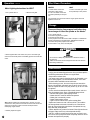
1
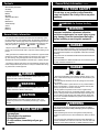
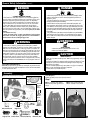
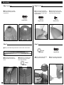
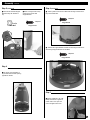
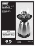
®
Patio Heater & Light
Model 5040-761
Model 5040B747
INSTRUCTIONS FOR USE
Patent # 6,422,232
Patent # 6,499,480
Patent # US D451,988 S
© 2003 The Coleman Company, Inc.
www.coleman.com
IMPORTANT
Read this manual carefully before assembling,
using or servicing this heater. Keep this manual for
future reference. If you have questions about
assembly, operation, servicing or repair of this
heater, please call Coleman at 1-800-835-3278 or
TDD: 316-832-8707.
In Canada call 1-800-387-6161.
®
®
1AS 9-96 & CSA International
Requirement 5.90 U.S.
General Safety Information continued.
Contents
General Safety Information
Assembly
Leak Check
Mantles
Operation
Shut Down Procedure
Storage
Maintenance
Troubleshooting
Service
Warranty
Parts List
FOR YOUR SAFETY
Do not store or use gasoline or other flammable
vapor and liquids in the vicinity of this or any other
appliance.
WARNING: For Outdoor Use Only
WARNING
General Safety Information
This manual contains important information about the assembly, operation and maintenance of this portable heater. General safety information is
presented in these first few pages and is also located throughout the manual. Particular attention should be paid to information accompanied by the
safety alert symbols: “ DANGER”, “ WARNING”, “ CAUTION”.
Keep this manual for future reference and to educate new users of this
product. This manual should be read in conjunction with the labeling on the
product.
Safety precautions are essential when any mechanical or propane fueled
equipment is involved. These precautions are necessary when using, storing, and servicing. Using this equipment with the respect and caution
demanded will reduce the possibilities of personal injury or property damage.
The following symbols shown below are used extensively throughout this
manual. Always heed these precautions, as they are essential when using
any mechanical or fueled equipment.
DANGER
DANGER indicates an imminently hazardous situation which, if not
avoided, will result in death or serious injury.
WARNING
WARNING indicates a potentially hazardous situation which, if not
avoided, could result in death or serious injury.
CAUTION
CAUTION indicates a potentially hazardous situation which, if not
avoided, may result in minor or moderate personal injury, or property
damage
FOR YOUR SAFETY
If you smell gas:
1. Shut off gas to the appliance.
2. Extinguish open flame.
3. If odor continues, immediately call your gas
supplier.
2
Improper installation, adjustment, alteration,
service or maintenance can cause injury or property damage. Read the instructions thoroughly
before installing or servicing this equipment
DANGER
Failure to comply with the precautions and instructions provided with this
heater can result in death, serious bodily injury and property loss or damage
from hazards of fire, explosion, burn, asphyxiation, and/or carbon monoxide
poisoning.
Only persons who can understand and follow the instructions should use or
service this heater.
If you need assistance or heater information such as an instruction manual
or labels, contact the Coleman Co., Inc.
DANGER
• EXPLOSION - FIRE HAZARD
• Keep solid combustibles, such as building materials, paper or cardboard, a safe distance away from the heater as recommended by the
instructions.
• Provide adequate clearances around air openings into the combustion chamber.
• Never use the heater in spaces which do or may contain volatile or
airborne combustibles, or products such as gasoline, solvents, paint
thinner, dust particles or unknown chemicals.
• During operation, this product can be a source of ignition. Keep
heater area clear and free from combustible materials, gasoline, paint
thinner, cleaning solvents and other flammable vapors and liquids. Do
not use heater in areas with high dust content. Minimum heater clearances from combustible materials: three (3) feet from the sides & two
(2) feet from the top.
WARNING
We cannot foresee every use which may be made of our heaters.
Check with your local fire safety authority if you have questions
about heater use.
Other standards govern the use of fuel gases and heat producing
products for specific uses. Your local authorities can advise you about
these.
If no local codes exist, follow National Fuel Gas Code, ANSI Z223.1. In
Canada, installation must conform to local codes. If no local codes exist,
follow the current National standards of CANADA CAN/CGA-B 149.2.
General Safety Information continued.
DANGER
DANGER
• CARBON MONOXIDE HAZARD
• This heater is a combustion appliance. All combustion appliances
produce carbon monoxide (CO) during the combustion process. This
product is designed to produce extremely minute, non-hazardous
amounts of CO if used and maintained in accordance with all warnings and instructions. Do not block air flow into or out of the heater.
• Carbon Monoxide (CO) poisoning produces flu-like symptoms,
watery eyes, headaches, dizziness, fatigue and possibly death. You
can't see it and you can't smell it. It's an invisible killer. If these symptoms are present during operation of this product get fresh air immediately!
• For outdoor use only.
• Never use inside house, or other unventilated or enclosed areas.
This heater consumes air (oxygen). Do not use in unventilated or
enclosed areas to avoid endangering your life.
• EXPLOSION - FIRE HAZARD
• Never store propane near high heat, open flames, pilot lights, direct
sunlight, other ignition sources or where temperatures exceed 120
degrees F (49°C).
• Propane is heavier than air and can accumulate in low places. If you
smell gas, leave the area immediately.
• Never install or remove propane tank while heater is lighted, near
flame, pilot lights, other ignition sources or while heater is hot to touch.
• This heater is red hot during use and can ignite flammables too close
to the burner. Keep flammables at least 3 feet from sides & 2 feet from
top. Keep gasoline and other flammable liquids and vapors well away
from heater.
• The propane tank must always be stored outdoors in a well ventilated
space. Never store propane tank in an enclosed area (house, garage,
etc.). If heater is to be stored indoors, disconnect the propane tank for
outdoor storage.
WARNING
WARNING
• This product is fueled by propane gas. Propane gas is invisible,
odorless, and flammable. An odorant is normally added to help detect
leaks and can be described as a ”rotten egg” smell. The odorant can
fade over time so leaking gas is not always detectable by smell alone.
• Propane gas is heavier than air and leaking propane will sink to the
lowest level possible. It can ignite by ignition sources including matches, lighters, sparks or open flames of any kind many feet away from
the original leak. Use only propane gas set up for vapor withdraw.
• Propane gas should be stored or used in compliance with local ordinances and codes or with ANSI/NFPA 58. Turn off propane when not
in use.
CALIFORNIA PROPOSITION 65:
WARNING: Propane and by-products of combustion of propane contain
chemicals known to the state of California to cause cancer, birth defects,
or other reproductive harm.
• BURN HAZARD
• Never leave heater unattended when hot or in use.
• Keep out of reach of children.
CAUTION
• SERVICE SAFETY
• Keep all connections and fittings clean. Make sure propane tank valve outlet is clean.
• Inspect hose before use. Replace if there is evidence of abrasion or wear.
• During set up, check all connections and fittings for leaks using soapy
water. Never use a flame.
• Use as a heating appliance only. Never alter in any way or use with any
device or part not expressly approved by Coleman.
• Check entire hose at least annually.
Assembly
■ Remove all components from package.
Tools Required
Phillips screwdriver and 7/16” open-end wrench
Step 1
Table not
included
on all
models.
■ Align 2 Cylinder Cover Pieces.
Place left piece over right piece as
shown.
■ Align holes in Post Base with
holes in Cylinder Cover Pieces.
12 Req’d
Acorn
Nuts
3 Req’d
Hex Nut
3 Req’d
Flat Head Screw
15 Req’d
Large Screw
3 Req’d
Edge Pins
6 Req’d
Small Screw
4 Req’d
Hex Head Screw
12 Req’d
Washers
3 Req’d
Reflector Bolt
3
Assembly
Step 1 (continued)
Step 2 (continued)
■ Attach Post Base to Cylinder
Cover Pieces loosely with seven
Large Screws.
■ Turn unit over and assemble
large screw loosely through Cover
Pieces into base of Center Rear
Support Bracket.
7 Required
Large Screw
1 Required
Large Screw
■ Assemble three small screws
loosely through Cover Pieces into
Center Rear Support Bracket.
3 Req’d
Small Screw
Step 3
Step 2
■ Identify Center Rear Support Bracket. It has six holes, various sizes.
1 Req’d
Hex Nut
■ Place Center Rear Support
Bracket in place over the center
screw.
■ Assemble one nut loosely over
the screw to attach the Center
Rear Support Bracket.
1 Req’d
Hex Nut
4
■ Attach a Side Support Bracket
loosely with Hex Nut at top.
1 Required
Large Screw
■ Attach one large screw loosely
at base of Side Support Bracket.
Assembly continued.
Step 3 (continued)
■ Attach the second Side Support
Bracket loosely with Hex Nut at
top.
Step 4 (continued)
■ Attach one large screw loosely
at base of the second Side
Support Bracket.
■ Attach Cylinder Cover Pieces to Base with two large screws horizontally into the Base Tabs.
2 Required
1 Required
Large Screw
1 Req’d
Hex Nut
Large Screw
■ Attach three Support Brackets to Base with three large screws downward through Support Brackets into the Base.
3 Required
Large Screw
Step 4
■ Set cylinder cover assembly on
top of heater base. Position opening
opposite the wheels.
Step 5
■ Tighten all fasteners. Use a #2
Phillips screwdriver to tighten all
screws. Use a 7/16" open end
wrench to tighten all hex nuts.
5
Assembly continued.
Step 6
Step 9
■ Install post onto post base.
■ Decal on post should face front
of heater (see photo on front
cover).
■ Attach post to post base using
four large screws.
■ Tighten screws securely.
■ Using the three screws removed in Step 8, securely attach clamp
assembly to support tubes.
3 Required
4 Required
Small Screw
Large Screw
Step 10
Step 7
■ Load cover onto post.
■ Slide cover down.
■ Load table onto post by sliding
table clamp over post and feed post
through center hole of table.
■ Slide table to desired position.
Step 11
(For models without a table, skip to Step 12)
■ Tighten clamp so table is secured to the post.
Step 8
■ Insert table supports into the receptors located in the underside of the
table frame.
NOTE: Screws must be backed out of the support tubes. Use those
screws to attach the clamp in the next step.
Friction Sleeve (between
clamp and post)
Support Tube
6
Gap in Sleeve should be
opposite gap in clamp
Assembly
continued.
Step 12
Step 14
■ Insert studs into screen cover.
■ Remove protective film from all reflector pieces prior to assembly.
■ Assemble Reflector Assembly
3 Req’d Brass Reflector Studs
9 Req’d
Acorn Nut
3 Req’d
Flat Head Screw
1
9 Req’d
Washers
3 Req’d
Edge Pins
2
Edge Pin
Upper Stud
Step 13
■ Install edge pins into the lower
lip of the reflector panel.
■ Place the other end of the Edge
Pin into a second panel of the
reflector. Place upper hole in second piece over upper stud.
3
4
■ Install the Flat Head Screw into
the hole from the bottom of the first
two reflector panels.
■ Loosely install the Flat Head
Screw in place with a washer and
Acorn Nut.
■ After repeating the above steps
to assemble the third reflector
panel, set the top cap in place and
secure with washers and acorn
nuts. Make sure all nuts are snug,
but DO NOT OVERTIGHTEN.
5
■ Load head assembly by inserting hose into post.
■ Insert head assembly into post.
■ Control knob should be above
decal on post.
■ Attach head assembly to post,
and loosely install three screws.
■ Tighten screws securely.
Step 15
3 Req’d
Acorn Nut
3 Req’d
Washers
■ Support Heater.
■ Locate assembled reflector
on 3 studs (ref. Step 12).
■ Install washers on studs &
securely tighten acorn nuts but
do not overtighten! Use a
7/16" nut driver or open-end
wrench.
3 Required
Small Screw
7
Assembly continued.
Step 16
■ Tighten Securely.
■ Install tank.
■ Attach regulator to tank.
■ Complete attachment.
• You must provide propane gas and propane tank. Use a standard 20 lb.
propane tank only.
• Use this heater only with a propane vapor withdrawal supply system. See
Chapter 5 of the Standard for Storage and Handling of Liquefied
Petroleum Gas, ANSI/NFPA 58. Your local library or fire department will
have this book.
• A minimum supply pressure of 11.0 W.C. is required for the purpose of
input adjustment for propane gas.
• The pressure regulator and hose assembly supplied with the appliance
must be used.
• The installation must conform with local codes, or in the absence of local
codes, with National Fuel Gas Code, ANSI Z223.1.
• A dented, rusted or damaged propane tank may be hazardous and should
be checked by your tank supplier. Never use a propane tank with a damaged valve connection.
• The propane tank must be constructed and marked in accordance with
the specifications for LP gas cylinders of the U.S. Department of
Transportation (DOT).
• Never connect an unregulated propane tank to the heater.
Standard 20 lb. tank
■ Install tank.
■ Screw regulator onto hose. Do not cross-thread.
8
Mantles
Leak Check
WARNING
•
•
•
•
■ Remove 2 glass panels.
Perform all leak tests outdoors.
Extinguish all open flames.
NEVER leak test when smoking.
Do not use the heater until all connections have been leak tested and
do not leak.
Hose/Regulator
Connection
Regulator/Cylinder
Connection
■ Slip mantle onto burners. Align clips in mantle with groove in burner. Be
sure clip points away from electrode.
• Make 2-3 oz. of leak check solution (one part liquid dishwashing
detergent and three parts water).
• Apply several drops of solution where hose attaches to regulator.
• Apply several drops of solution where regulator connects to Cylinder.
• Make sure all Patio Heater & Light valves are OFF.
• Turn Cylinder Valve ON.
If bubbles appear at any connection, there is a leak.
• Turn Cylinder Valve OFF.
• If leak is at Hose/Regulator connection: tighten connection and perform
another leak test. If you continue to see bubbles after several attempts,
contact 1-800-835-3278 for assistance.
• If leak is at Regulator/Cylinder Valve connection: disconnect, reconnect,
and perform another leak check. If you continue to see bubbles after several attempts, cylinder valve is defective and should be returned to cylinder’s place of purchase.
If NO bubbles appear at any connection, the connections are secure.
• Turn Cylinder Valve OFF.
NOTE: Whenever gas connections are loosened or removed, you
must perform a complete leak test.
■ Lift cover while installing
remaining cylinder cover section.
Groove
Electrode
■ Twist clips.
■ Complete installation.
9
Mantles continued.
Operation
■ Attach second mantle. Illustration below shows proper assembly of both
mantles.
DANGER
• CARBON MONOXIDE HAZARD
• For outdoor use only. Never use inside house, or other unventilated
or enclosed areas. This heater consumes air (oxygen). Do not use in
unventilated or enclosed areas to avoid endangering your life.
DANGER
■ Light bottom of mantles evenly. Burn until nothing but white ash remains.
Once mantle has been burned it’s very fragile. Be careful not to touch it
with a finger or match. Install glass panels.
• EXPLOSION - FIRE HAZARD
• Never store propane near high heat, open flames, pilot lights, direct
sunlight, other ignition sources or where temperatures exceed 120
degrees F (49°C).
• Propane is heavier than air and can accumulate in low places. If you
smell gas, leave the area immediately.
• Never install or remove propane tank while heater is lighted, near
flame, pilot lights, other ignition sources or while heater is hot to touch.
• This heater is red hot during use and can ignite flammables too close
to the burner. Keep flammables at least 3 feet from sides & 2 feet from
top. Keep gasoline and other flammable liquids and vapors well away
from heater.
• The propane tank must always be stored outdoors in a well ventilated
space. Never store propane tank in an enclosed area (house, garage,
etc.). If heater is to be stored indoors, disconnect the propane tank for
outdoor storage.
• Do not attempt to operate until you have read & understand all General
Safety Information in this manual and all assembly is complete & leak
checks have been performed.
Lighting Instructions for HEATER
Battery Installation for HEATER
■ Unscrew igniter button to reveal battery compartment.
■ Install AA battery with positive (+) outward.
■ Replace igniter button finger tight.
■ Turn cylinder valve on.
1. Push in and rotate (counter clockwise) heater control knob to the
Pilot position and release.
2. Push in on heater control knob and push Igniter Button to ignite
Pilot Light.
Note: Initial lighting after gas cylinder change can take up to two (2)
minutes to purge any air that may be in the line.
10
Operation
continued.
Lighting Instructions for HEATER continued.
Match Lighting Instructions for HEATER
3. Pilot Light will ignite and be
visible through Pilot Viewing Port
(flame may be difficult to see in
broad daylight). Continue to push
Heater Control Knob in for 30 to
60 seconds after pilot is on, then
release knob. Pilot Light must
remain on, if not return to
step 1.
Pilot
Viewing
Port
1. Turn cylinder valve on.
2. Push in and rotate (counter
clockwise) Heater Control Knob
to the Pilot position and release.
Pilot
Port
Note: If pilot fails to remain lighted, all valves should be closed and a
waiting period of at least 5 minutes should pass before attempting to
light.
4. Rotate Heater Control Knob to ON position. Heater burner will light and
be visible through screen of heater. If Main burner does not light, turn off
Heater Control Knob and return to Step 1.
3. Use a long match. Locate Pilot Port directly above center glass panel.
4. Light a long fireplace match (minimum 4" long) and insert into Pilot
Port, then push in and hold Heater Control Knob.
5. Pilot light will ignite and be visible from Pilot Port or Pilot Viewing Port.
Continue to push Heater Control Knob in for 30 to 60 seconds after
pilot is on, then release knob. Pilot light must remain on, if not return to
Step 1.
Heater
Control
Knob
Igniter
Pilot
Port
Lighting Instructions for LIGHT
1. Push in and rotate Light Control Knob to the ON position while pushing
the Igniter Button until BOTH mantles are lighted.
Note: If BOTH mantles are not lighted within 5 seconds, turn Light
Control Knob to OFF position. All controls should be turned to the OFF
position and a period of at least 5 minutes should pass before
reattempting to light burners.
2. Mantles will light and begin to
glow which can be seen through
the windows. If the mantles do not
light or fail to remain lighted turn
OFF Light Control Knob and return
to Step 1.
Note: If pilot fails to remain lighted, all valves should be closed and
a waiting period of at least 5 minutes should pass before attempting
to light.
■ Unit can be operated with
heater & light both operating or
either operating separately.
6. Rotate Heater Control Knob to ON position. Heater burner will light
and be visible through screen of heater. If Heater burner does not light,
turn off Heater Control Knob and return to Step 1.
Light
Control
Knob
Igniter
11
Operation
Shut Down Procedure
continued.
Match Lighting Instructions for LIGHT
1. Turn cylinder valve on.
2. Remove front glass.
HEATER
LIGHT
1. Rotate Heater control knob
(clockwise) to pilot position.
2. Push in on Heater control knob
and rotate (clockwise) to OFF position.
1. Push in and rotate Light control
knob (clockwise) to OFF position.
The gas supply must be turned off at the LP-gas cylinder when this
appliance is not in use.
Storage
Disconnect heater from propane tank before long
term storage of either the cylinder or the Heater.
1. Turn cylinder valve off.
2. Disconnect regulator from cylinder.
3. Remove tank from Heater.
4. Store propane tank in safe manner. Refer to Chapter 5 of Standard for
Storage and Handling of Liquefied Gases, ANSI/NFPA 58. Follow all
local codes. Always store propane tanks outdoors.
5. Store heater in a dry, clean, and safe place.
WARNING
3. Place a lighted match near mantle, then push in and rotate Light
Control Knob to the ON position. Immediately light second mantle with
match.
• BURN HAZARD
• Do not touch or attempt any maintenance on Heater for at least 1
hour after use.
• Make sure all controls are off and propane tank has been removed
before doing maintenance.
Maintenance
Note: If BOTH mantles are not lighted within 5 seconds, turn Light
control knob to OFF position. All controls should be turned to the OFF
position and a period of at least 5 minutes should pass before
reattempting to light mantles.
4. Carefully replace front glass.
12
To enjoy years of outstanding performance from your Heater perform
the following maintenance activities on a regular basis:
• Keep exterior surfaces clean.
• Use warm soapy water for cleaning. Never use flammable or corrosive cleaning agents. For stainless steel surfaces, use a stainless steel cleaner available at most retail stores.
• While cleaning your unit, be sure to keep the area around the
burner, pilot assembly and mantle area dry at all times. If the regulator is exposed to water in any way, do NOT try to use it. It must
be replaced.
• Air flow must be unobstructed. Keep controls, burner, and circulating air passages clean. Signs of possible blockage include:
• Gas odor with extreme yellow tipping of flame.
• Heater does NOT reach the desired temperature.
• Heater glow is excessively uneven.
• Heater makes popping noises.
• Light is uneven or burns with a yellow smokey flame.
• Spiders and insects can nest in burner orifices. This condition
can damage heater and render it unsafe for use. Clean burner
holes by using a heavy-duty pipe cleaner. Compressed air may
help clear away small particles.
• Carbon deposits may create a fire hazard. Clean light and burner
with warm soapy water if any carbon deposits develop.
• NOTE: In a salt-air environment (such as near an ocean), corrosion occurs more quickly than normal. Frequently check for corroded areas and repair them promptly.
Troubleshooting
Problem
Possible Cause
Solution
Pilot won’t light
Cylinder valve is closed
Open valve
Blockage in orifice or pilot tube
Clean or replace orifice or pilot tube
Air in gas line
Pilot may take 1-2 minutes to light after a propane bottle
has been connected
Low gas pressure with Cylinder Valve
fully open
Cylinder is empty. Replace cylinder
Igniter fails
Use match to light pilot. Obtain new igniter and
replace
Heater control knob not fully
depressed in pilot position when
lighting pilot
Depress heater control knob firmly in light position
when lighting pilot
No spark at burner electrode
Use match to light pilot. If wire to electrode is
damaged - replace with new wire and/or carbon
across spark gap
Dirt built up around pilot
Clean dirt from around pilot
Connection between gas valve and
pilot assembly is loose
Tighten connection and perform leak check
Thermocouple is not operating
correctly
Tighten all thermocouple connections. Replace
if faulty
Gas pressure is low
Turn Cylinder valve OFF and replace cylinder
Blockage in orifice
Clear blockage
Control knob is not in ON position
Turn control knob to ON
Gas pressure is low
Turn Cylinder valve OFF and replace cylinder
Blockage in orifice
Clear blockage
Control knob is not in ON position
Turn control knob to ON
Igniter fails
Use match to light pilot. Obtain new igniter and
replace
Gas pressure is low
Turn Cylinder valve OFF and replace cylinder
Outdoor temperature is less than 40° F
and tank is less than 1/4 full
Use a full cylinder
Supply hose is bent or kinked
Straighten hose
Control knob fully ON
Check burner and orifices for blockage
Dirt or film on reflector and burner screen
Remove blockage from burner screen holes and clean
burner screen inside and outside
Pilot won’t stay lit
Burner won’t light
Light won’t light
Burner flame is low
NOTE: Do not operate
heater below 0° F.
Carbon build-up
Thick black smoke from Blockage in burner or in light gas passages
burner or light
Remove blockage and clean burner inside and outside
Mantles light but dim
out when heater is
turned on.
Faulty Regulator (First insure cylinder
valve is fully open and that cylinder is
not empty)
Replace regulator
Pilot lights but Heater
flame is “lazy” or has
low output.
Faulty Regulator (First insure cylinder
valve is fully open and that cylinder is
not empty)
Replace regulator
Service
• Repair to gas passages and associated components should be done only by a qualified service person.
• Owner repair & service should be limited and performed only to the
following:
- Mantle replacement
- Glass replacement
- Reflector replacement
13
Replacement Parts - Patio Heater & Light
14
1
20
19
11
2
7
12
17
16
3
8
10
4
5
13
6
No.
1
2
3
4
5
6
7
8
9
10
11
12
13
14
15
16
17
18
19
20
14
Part No.
5040-1551
5040B5441
5040-1221
5040-1461
5040-1511
5040-1451
5040-3101
5040-5571
5040-2211
5040-5261
5040-5651
21A122
5040-0801
5040-4451
5040-4471
5040-4401
5040-4771
5040-1751
5040-4831
5040-4871
5040-1251
5040-1261
5040-0731
5040-0771
5040-1141
5040-1181
Description
Reflector including hardware
Pilot Assembly (Including tip switch)
Glass and Frame
Heater Knob
Lantern Knob
E.I. Button
Electrode
Lantern & Heater Valve Assembly
Igniter
Regulator
Gas Hose Less Regulator
Insta-Clip Mantle
Hardware Kit Complete
Three Panels (Painted, Pewter)
Three Panels (Painted, Silver Vein)
Post (Painted, Pewter)
Post (Painted, Silver Vein)
Base Assembly with Wheels
Post Mount (Painted, Pewter)
Post Mount (Painted, Silver Vein)
Post Mount Cover (Painted, Pewter)
Post Mount Cover (Painted, Silver Vein)
Three Support Brackets (Painted, Pewter)
Three Support Brackets (Painted, Silver Vein)
Heater Burner Screen
Burner
9
15
18
Replacement Parts - Table
Parts List
No. Part No.
1
5040-1031
5040-1071
2
5040-1032
5040-0871
3
5040A1033
5040-0171
Description
Table Assembly (Painted, Pewter)
Table Assembly (Painted, Silver Vein)
Table Support & Hardware (Painted, Pewter)
Table Support & Hardware (Painted, Silver Vein)
Clamp (Painted, Pewter)
Clamp (Painted, Silver Vein)
3
2
1
15
Warranty
Coleman Limited 5-Year Warranty
Coleman will repair or replace, at its option, this product or any component found to be defective in materials or
workmanship within five years of the original retail purchase.
This warranty is valid for the original retail purchaser from the date of initial retail purchase and is not transferrable.
Keep the original sales receipt. Proof of purchase is required to obtain warranty performance. Coleman dealers,
service centers, or retail stores offering Coleman products do not have authority to alter, modify or in
any way change the terms or conditions of this warranty.
WHAT IS NOT COVERED
■ Cost of shipment to Coleman
■ Normal wear and tear, including chips, scratches, abrasion, discoloration or fading from use or
exposure to sunlight
■ Damage caused by misuse, abuse, neglect, alterations, repairs by unauthorized persons, use of
non-Coleman accessories or parts, or failure to follow recommended care or maintenance instructions
■ Products used for commercial purposes or in profit or non-profit instructional or rental operations
■ Mantles, generators, light bulbs, batteries or fuel
■ CONSEQUENTIAL DAMAGES, INCIDENTAL DAMAGES, OR EXPENSES, INCLUDING
DAMAGES TO PROPERTY. SOME STATES/PROVINCES DO NOT ALLOW THE EXCLUSION
OR LIMITATION OF INCIDENTAL OR CONSEQUENTIAL DAMAGES, SO THE ABOVE
LIMITATION OR EXCLUSION MAY NOT APPLY TO YOU.
IMPLIED WARRANTIES
Any implied warranties, either statutory or otherwise, including implied warranties of merchantability and fitness
for a particular purpose, shall be limited to the duration and terms of the express warranties set forth in this limited
warranty. Some states/provinces do not allow limitations on how long an implied warranty lasts, so the above
limitation may not apply to you.
HOW TO OBTAIN WARRANTY PERFORMANCE
Take the product to an authorized Coleman Service Center. If one is not conveniently located, attach a tag to the
product which includes your name, address, telephone number and description of the problem. Include a copy of the
original sales receipt. Carefully package the product and send either by UPS or Parcel Post insured with shipping
and insurance prepaid to: USA: The Coleman Company Inc., 3600 N. Hydraulic, Wichita, KS 67219, or CANADA:
The Canadian Coleman Co., Ltd., 5975 Falbourne Street, Mississauga, Canada L5R 3V8. Please do not mail
products with fuel in tanks, or with disposable propane cylinders. Remove glass globes from lanterns.
If you are located outside the United States or Canada, return this product to the place you purchased it, or to
any other retailer seller of similar Coleman products, and request warranty assistance. If you are unable to obtain
warranty assistance, then you may call any of the following Coleman offices for further assistance:
www.coleman.com
5 - YEAR
The Coleman Co., Inc.
3600 N. Hydraulic
Wichita, KS 67219 U.S.A.
1-800-835-3278
TDD: 316-832-8707
®
The Coleman Co., Inc. • 3600 N. Hydraulic
Wichita, KS 67219 U.S.A.
1-800-835-3278 • TDD: 316-832-8707
16
©2003 The Coleman Company, Inc. All rights reserved.
Coleman® is a registered trademark of The Coleman Company, Inc.
5040-034 (10/03)