1
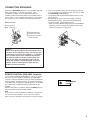
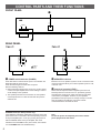
MX-1
MX-2
Natural Sound Stereo Power Amplifier
CONTENTS
Safety Instructions ..................... 2
Features ................................... 3
Connections ............................. 4
Control Parts and Their
Functions ................................. 6
Troubleshooting ........................ 7
Specifications ........................... 8
OWNER’S MANUAL
SAFETY INSTRUCTIONS
6A A unit and cart combination should
be moved with care. Quick stops,
excessive force, and uneven
surfaces may cause the unit and cart
combination to overturn.
CAUTION
RISK OF ELECTRIC SHOCK
DO NOT OPEN
CAUTION: TO REDUCE THE RISK OF
ELECTRIC SHOCK, DO NOT REMOVE
COVER (OR BACK), NO USER-SERVICEABLE
PARTS INSIDE, REFER SERVICING TO
QUALIFIED SERVICE PERSONNEL.
7
Wall or Ceiling Mounting – The unit should be mounted to
a wall or ceiling only as recommended by the
manufacturer.
8
Ventilation – The unit should be situated so that its location
or position does not interfere with its proper ventilation.
For example, the unit should not be situated on a bed,
sofa, rug, or similar surface, that may block the ventilation
openings; or placed in a built-in installation, such as a
bookcase or cabinet that may impede the flow of air
through the ventilation openings.
9
Heat – The unit should be situated away from heat sources
such as radiators, stoves, or other appliances that produce
heat.
• Explanation of Graphical Symbols
The lightning flash with arrowhead
symbol, within an equilateral triangle,
is intended to alert you to the
presence of uninsulated “dangerous
voltage” within the product’s
enclosure that may be of sufficient
magnitude to constitute a risk of
electric shock to persons.
The exclamation point within an
equilateral triangle is intended to alert
you to the presence of important
operating and maintenance
(servicing) instructions in the
literature accompanying the
appliance.
10 Power Sources – The unit should be connected to a power
supply only of the type described in the operating
instructions or as marked on the unit.
11 Power-Cord Protection – Power-supply cords should be
routed so that they are not likely to be walked on or
pinched by items placed upon or against them, paying
particular attention to cords at plugs, convenience
receptacles, and the point where they exit from the unit.
12 Cleaning – The unit should be cleaned only as
IMPORTANT!
Please record the serial number of this unit in
the space below.
Model:
Serial No.:
The serial number is located on the rear of the
unit.
Retain this Owner’s Manual in a safe place for
future reference.
recommended by the manufacturer.
13 Nonuse Periods – The power cord of the unit should be
unplugged from the outlet when left unused for a long
period of time.
14 Object and Liquid Entry – Care should be taken so that
objects do not fall into and liquids are not spilled into the
inside of the unit.
15 Damage Requiring Service – The unit should be serviced
by qualified service personnel when:
WARNING
TO REDUCE THE RISK OF FIRE OR
ELECTRIC SHOCK, DO NOT EXPOSE THIS
UNIT TO RAIN OR MOISTURE.
A. The power-supply cord or the plug has been damaged;
or
B. Objects have fallen, or liquid has been spilled into the
unit; or
C. The unit has been exposed to rain; or
1
Read Instructions – All the safety and operating
instructions should be read before the unit is operated.
D. The unit does not appear to operate normally or
2
Retain Instructions – The safety and operating instructions
should be retained for future reference.
E. The unit has been dropped, or the cabinet damaged.
3
Heed Warnings – All warnings on the unit and in the
operating instructions should be adhered to.
4
Follow Instructions – All operating and other instructions
should be followed.
5
Water and Moisture – The unit should not be used near
water – for example, near a bathtub, washbowl, kitchen
sink, laundry tub, in a wet basement, or near a swimming
pool, etc.
6
2
Carts and Stands – The unit should be used only with a
cart or stand that is recommended by the manufacturer.
exhibits a marked change in performance; or
16 Servicing – The user should not attempt to service the unit
beyond those means described in the operating
instructions. All other servicing should be referred to
qualified service personnel.
17 Power Lines – An outdoor antenna should be located away
from power lines.
18 Grounding or Polarization – Precautions should be taken
so that the grounding or polarization is not defeated.
19 Speaker Connection – To reduce the risk of shock or
fire and prevent short circuits, strictly follow the
instructions for connecting speakers on page 5.
Caution: Read this before operating your unit
1
To ensure the finest performance, please read this
manual carefully. Keep it in a safe place for future
reference.
2
Install your unit in a cool, dry, clean place – away from
windows, heat sources, and too much vibration, dust,
moisture or cold. Avoid sources of hum (transformers,
motors). To prevent fire or electrical shock, do not
expose to rain and water.
3
Do not operate the unit upside-down. It may overheat,
possibly causing damage.
4
Never open the cabinet. If a foreign object drops into
the set, contact your dealer.
5
Do not place records or other objects on top of the unit;
this will block the ventilation holes, cause the internal
temperature to rise and may result in a failure.
6
Do not use force on switches, knobs or cords. When
moving the set, first turn the unit off. Then gently
disconnect the power plug and the cords connecting to
other equipment. Never pull the cord itself.
7
Do not attempt to clean the unit with chemical solvents;
this might damage the finish. Use a clean, dry cloth.
8
To prevent lightning damage, pull out the power cord
and remove the antenna cable during an electrical
storm.
9
When not planning to use this unit for long periods of
time (ie., vacation, etc.), disconnect the AC power plug
from the wall outlet.
10 Be sure to read the “Troubleshooting” section on
common operating errors before concluding that your
unit is faulty.
We Want You Listening For A Lifetime
YAMAHA and the Electronic Industries Association’s
Consumer Electronics Group want you to get the most out of
your equipment by playing it at a safe level. One that lets the
sound come through loud and clear without annoying blaring or
distortion – and, most importantly, without affecting your
sensitive hearing. Since hearing damage from loud sounds is
often undetectable until it is too late, YAMAHA
and the Electronic Industries Association’s
Consumer Electronics Group recommend you to
avoid prolonged exposure from excessive
volume levels.
FEATURES
●
●
●
●
●
<MX-1>:
<MX-2>:
200W + 200W (8Ω) RMS Output Power, 0.008% THD, 20–20,000 Hz
150W + 150W (8Ω) RMS Output Power, 0.008% THD, 20–20,000 Hz
Increased Low Impedance Drive Capability
2-Pair Speaker Drive Capability
REMOTE CONTROL Connector to Make the Power of This Unit Controlled
by the Pre-Amplifier CX-1 or CX-2
Gold-Plated Input Terminals
3
CONNECTIONS
●
●
Before attempting to make any connections to or from this unit, be sure to first switch OFF the power to this unit and to any other
components to which connections are being made.
When making connections between this unit and other components, be sure all connections are made correctly, that is to say L
(left) to L, R (right) to R, “+” to “+” and “–” to “–”. Also, refer to the owner’s manual for each component to be connected to this
unit.
<MX-1>
Speakers A
Pre-amplifier etc.
Left
Right
REMOTE
CONTROL
PRE OUT
(U.S.A. model)
LEVEL
INPUT
REMOTE CONTROL
( PRE AMP )
A OR B:2ΩMIN. / SPEARKER
A + B :4ΩMIN. / SPEARKER
A OR B:2ΩMIN. / HAUT-PARLEUR
A + B :4ΩMIN. / HAUT-PARLEUR
To AC outlet
Left
Right
Speakers B
<MX-2>
Speakers A
Pre-amplifier etc.
Left
Right
REMOTE
CONTROL
PRE OUT
(U.S.A. model)
LEVEL
REMOTE CONTROL
( PRE AMP )
A OR B:2ΩMIN. / SPEARKER
A + B :4ΩMIN. / SPEARKER
A OR B:2ΩMIN. / HAUT-PARLEUR
A + B :4ΩMIN. / HAUT-PARLEUR
INPUT
To AC outlet
Left
Right
Speakers B
4
CONNECTING SPEAKERS
Connect the SPEAKERS terminals to your speakers with wire
of the proper gauge, cut as short as possible. If the
connections are faulty, no sound will be heard from the
speakers. Make sure that the polarity of the speaker wires is
correct, that is, + and – markings are observed. If these wires
are reversed, the sound will be unnatural and will lack bass.
How to Connect:
Red: positive (+)
Black: negative (–)
●
●
●
One or two speaker systems can be connected to this unit.
If you connect only one speaker system, connect it to either
the SPEAKERS A or B terminals.
Use speakers with the specified impedance shown on the
rear of this unit.
Banana Plug connections are also possible (except for
Scandinavian models). Simply insert the Banana Plug
connector into the corresponding terminal.
*When connecting Banana Plugs to this unit’s SPEAKERS
terminals, be sure to tighten the terminal knobs to make
contact securely before connections.
➁
➀ Unscrew the knob.
➁ Insert the bare wire.
➂ Tighten the knob and
secure the wire.
➂
➀
Caution
When inserting the stripped ends of the speaker wires
as shown above, make sure at least 1/16 inch (1.6 mm)
of insulation is inside the wire holders (i.e. no exposed
wire is visible) and no loose conductor wire strands
are protruding after connection. If wires touch each
other or they touch the metal parts of this unit, this
unit and/or speakers could be damaged. To prevent
speaker wires from coming loose, make sure wire
holders are firmly screwed in.
REMOTE CONTROL (PRE AMP) connector
If you have the YAMAHA pre-amplifier CX-1 or CX-2, connect
this connector to the REMOTE CONTROL (POWER AMP)
connector of the pre-amplifier by using the cable provided with
the pre-amplifier. By this connection, the power of this unit is
controlled by the pre-amplifier’s POWER switch or the POWER
key of the remote control transmitter provided with the preamplifier.
After the connection is completed, keep the POWER switch of
this unit pressed inward (to the ON position).
Note
If you will not connect the REMOTE CONTROL connectors of
this unit and the pre-amplifier, do not connect the cable to
either connector. Otherwise, this unit will not function normally.
REMOTE CONTROL
( PRE AMP )
5
CONTROL PARTS AND THEIR FUNCTIONS
FRONT PANEL
➊
SPEAKERS
➋
REAR PANEL
<MX-1>
<MX-2>
➌
➌
LEVEL
LEVEL
INPUT
REMOTE CONTROL
( PRE AMP )
REMOTE CONTROL
( PRE AMP )
INPUT
➊
POWER switch/indicator (POWER)
Press this switch to switch ON the power. The indicator will
illuminate while the power is ON.
Press the switch again to switch OFF the power.
Note the following cautions.
● Before switching ON the power, be sure to set the volume
control of the pre-amplifier to the lowest setting in order to
avoid damage to the speakers.
● The speaker-protection circuit functions to mute speaker
sound reproduction for a few seconds after the power is
switched ON.
STANDBY mode (For Europe model only)
If the REMOTE CONTROL (PRE AMP) connector on the rear
panel of this unit is connected to the corresponding connector
of the pre-amplifier (CX-1 or CX-2), by turning the power off
with the POWER switch of the pre-amplifier, this unit is
switched to the STANDBY mode. (In this mode, the indicator
over the POWER switch is half illuminated.)
6
➋
SPEAKERS switches
Because one or two speaker systems can be connected to this
unit, these switches allow you to select speaker system A or B,
or both at once.
➌
Input level controls (LEVEL)
These controls adjust the level of signals input to this unit.
Normally set these controls to the “10” (maximum) position,
and adjust the whole sound output level with the VOLUME
control of the pre-amplifier. However, if your speakers’
permissible music input power is not high enough or sounds
from the speakers are distorted, turn these controls
counterclockwise to decrease the level.
Note
To turn the power off completely, disconnect the AC
power plug from the wall outlet.
TROUBLESHOOTING
If the unit fails to operate normally, check the following points to determine whether the fault can be corrected by the simple
measures suggested. If it cannot be corrected, or if the fault is not listed in the SYMPTOM column, disconnect the power cord and
contact your authorized YAMAHA dealer or service center for help.
SYMPTOM
CAUSE
REMEDY
The unit fails to turn on when the
POWER switch is pressed.
Power cord is not plugged in or is not
completely inserted.
Firmly plug in the power cord.
No sound.
The SPEAKERS switches are released
outward to the “OFF” position.
Press them inward to the “ON” position.
The speaker level controls are set to the
fully counterclockwise position.
Turn them clockwise.
Connection cords are not connected
securely to the INPUT terminals.
Connect them securely.
Speaker systems are not properly
connected to this unit.
Connect them correctly.
The sound suddenly goes off.
The protection circuit has activated
because of short circuit etc.
Turning the unit off and then on will
reset the protection circuit.
No sound is heard from the left
and/or right speaker systems.
Speaker systems are not properly
connected to this unit.
Connect them correctly.
The input level controls are set to the
fully counterclockwise position.
Turn the input level controls clockwise.
The acoustic “image” is unstable,
characterized by unnatural sound
and insufficient low-range tonal
quality.
The positive (+) and negative (–)
polarities (of this unit and the speaker
systems) are not matched.
Reconnect the speaker systems to this
unit so that the polarities are aligned.
Hum noise is heard from the
speakers.
Connection cords are not connected
securely to the INPUT terminals.
Connect them securely.
7
SPECIFICATIONS
Minimum RMS Output Power per Channel
<MX-1>
8 ohms, 20 Hz to 20 kHz, 0.008% THD ..............200W+200W
4 ohms, 20 Hz to 20 kHz, 0.03% THD ................260W+260W
2 ohms, 20 Hz to 20 kHz, 0.09% THD ................320W+320W
<MX-2>
8 ohms, 20 Hz to 20 kHz, 0.008% THD ..............150W+150W
4 ohms, 20 Hz to 20 kHz, 0.03% THD ................190W+190W
2 ohms, 20 Hz to 20 kHz, 0.09% THD ................230W+230W
Dynamic Power per Channel
(by IHF Dynamic Headroom measuring method)
<MX-1>
8/4/2 ohms .....................................................280/460/630W
<MX-2>
8/4/2 ohms .....................................................190/310/410W
DIN Standard Output Power per Channel
(4 ohms, 1 kHz, 0.5% THD)
[Europe model only]
<MX-1> ......................................................................300W
<MX-2> ......................................................................210W
Dynamic Headroom
<MX-1>
8/4/2 ohms ................................................1.46/2.48/2.94 dB
<MX-2>
8/4/2 ohms ................................................1.03/2.12/2.51 dB
IEC Power (8 ohms, 1 kHz, 0.01% THD)
[Europe model only]
<MX-1> ......................................................................225W
<MX-2> ......................................................................175W
Power Band Width
<MX-1>
8 ohms, 100W, 0.03% THD .........................10 Hz to 60 kHz
<MX-2>
8 ohms, 75W, 0.03% THD ...........................10 Hz to 60 kHz
Damping Factor
8 ohms, 1 kHz ......................................................250 or more
8 ohms, 20 Hz–20 kHz
(When using the SPEAKERS A terminals) ........350 or more
Input Sensitivity/Impedance
MAIN IN
<MX-1> ....................................................1.46V/20 k-ohms
<MX-2> ....................................................1.26V/20 k-ohms
Frequency Response (20 Hz to 20 kHz)
MAIN IN.....................................................................0±0.5 dB
Signal-to-Noise Ratio (IHF-A Network)
MAIN IN (Input Shorted)
<MX-1> ................................................................... 125 dB
<MX-2> ................................................................... 123 dB
Residual Noise (IHF-A Network) ......................................20 µV
Channel Separation (Vol. –30 dB)
MAIN IN (Input 5.1 k-ohms Terminated 1 kHz/10 kHz)
...........................................................................80 dB/60 dB
Power Supply
[U.S.A. and Canada models] .......................AC 120V, 60 Hz
[Australia and U.K. models] .........................AC 240V, 50 Hz
[Europe model] ............................................AC 230V, 50 Hz
[General model] .................AC 110/120/220/240V, 50/60 Hz
Power Consumption
<MX-1>
[U.S.A. and Canada models]..........................560 VA, 420W
[Australia, U.K. and General models]...........................440W
[Europe model].............................................................550W
<MX-2>
[U.S.A. and Canada models]..........................440 VA, 340W
[Australia, U.K., Europe and General models] .............360W
Maximum Power Consumption (10% THD)
[General model only]
<MX-1> ....................................................................1950W
<MX-2> ....................................................................1600W
Dimensions (W x H x D) ............................486 x 116 x 438 mm
(19-1/8” x 4-9/16” x 17-1/14”)
Weight
<MX-1> .............................................24.0 kg (52 lbs. 13 oz.)
<MX-2> .............................................19.5 kg (42 lbs. 14 oz.)
Specifications subject to change without notice.
YAMAHA
YAMAHA
YAMAHA
YAMAHA
YAMAHA
YAMAHA
YAMAHA
ELECTRONICS CORPORATION, USA 6660 ORANGETHORPE AVE., BUENA PARK, CALIF. 90620, U.S.A.
CANADA MUSIC LTD. 135 MILNER AVE., SCARBOROUGH, ONTARIO M1S 3R1, CANADA
ELECTRONIK EUROPA G.m.b.H. SIEMENSSTR. 22-34, D-2084 RELLINGEN BEI HAMBURG, F.R. OF GERMANY
ELECTRONIQUE FRANCE S.A. 17 RUE DES CAMPANULES, LOGNES 77321 MARNE LA VALLEE CEDEX 2, FRANCE
ELECTRONICS (UK) LTD. YAMAHA HOUSE, 200 RICKMANSWORTH ROAD WATFORD, HERTS WD1 7JS, ENGLAND
SCANDINAVIA A.B. J A WETTERGRENS GATA 1, BOX 30053, 400 43 VÄSTRA FRÖLUNDA, SWEDEN
MUSIC AUSTRALIA PTY, LTD. 17-33 MARKET ST., SOUTH MELBOURNE, 3205 VIC., AUSTRALIA
VQ13100-0 BWWO,O
Printed in Japan