1
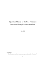
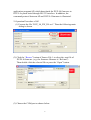
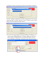
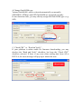
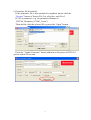
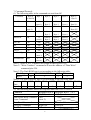
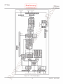
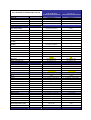
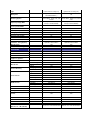
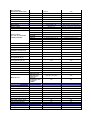
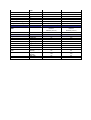
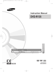
SAFETY PRECAUTIONS GENERAL GUIDELINES 1. Always use the manufacturer’s replacement safety components. The critical safety components marked with on the schematics diagrams should not be by other substitutes. Other substitute may create the electrical shock , fire or other hazards. Take attention to replace the spacers with the originals. Furthermore where a short circuit has occurred , replace those components that indicate evidence of overheating. 2. After servicing , see that all the protective devices such as insulation barriers, insulation papers, shields and isolation R-C combinations are correctly installed. 3. When the receiver is not being used for a long time of period of time , unplug the power cord of the Adaptor from the AC outlet. Color TFT LCD Module is very sensitive both electrically and physically.Users, therefore, are requested to follow the “Guidance of handling color TFT LCD Module”on the followings. Be careful not to make scratch on the polarizer. Surface of polarizer is soft and can be physically damaged easily. Please do not touch, push or rub polarizer surface with materials over HB hardness. 1- 2Keep clean the surface. Please wear rubber glove when touch the surface of LCD screen. Please use soft and anti-static material as cleaner. 3Keep out of water. Water on/in the LCD may cause electrical short or corrosion. Please wipe out dry or water carefully. 4- Prevent swift Temperature & Humidity change. Instantaneous temperature and/or humidity change can make dew or ice which cause nonconformance such as malfunction. 5 High temperature & high humidity reduce the life-time. LCD is not proper to be used at high temperature and high humidity. Please keep specified temperature and humidity condition. 6- Keep out of Corrosive Gas. Corrosive gas effect the polarizer and the circuit chemically and cause defects accordingly. 7 - Electrostatic discharge can make Damage There are electro-static sensitive components such as CMOS in LCD Module. Please earth human body when handle the LCD.In addition, please do not touch the interface connector pin with bare. 8- Do not operate for a long time under the same pattern Operating LCD for a long time under the same pattern can cause image persistence and can damage it. Please follow following guidance. 1. Turn the power off when do not use. 2. Change the pattern periodically. Operation Manual of DVP-L4 Firmware Download through RS-232 Interface Rev. 0.4 1. Purpose: This Document explains the operation procedure of the Windows 1 application program(AP) which downloads the DVP-L4 firmware to DVP-L4 system board through RS-232 interface. In addition, the command protocol between AP and DVP-L4 firmware is illustrated. 2. Operation Procedure of AP: (1) Execute the file “DVP_L4_FW_DL.exe”. Then the following main dialog is shown. (2) Click the “Browse” button of Source File 1 to select the .mot file of DVP-L4 firmware. (e.g. the firmware filename is “Ref.mot”). Then double click the selected file or press the “Open” button. (3) Choose the COM port as shown below: 2 (4) Connect your selected COM port of PC to the terminal board via RS-232 cable as shown below. (5) Press the “Update Firmware” button and then a dialog will appear as 3 below. Please turn on the power of DVP-L4 system within 30 seconds. (6) After power on, the title bar of the dialog will become “Erasing” soon. (7) After erasing is finished (about 5 second), the title bar of the dialog becomes “Writing” as below. The progress bar shows the percentage of progress. (8) After writing is finished, the title bar of the dialog becomes 4 “Verifying” as below. The progress bar shows the percentage of progress. (9) After verifying is finished successfully, the dialog shows the message “Download OK!!” as below. Then press “Close” button to return to main dialog. And the download procedure is done. 3. If your PC can support higher baud rate(115200bps~921600bps), or it cannot support default baud rate of 57600bps, change the baud rate as below. If you use USB-to-RS232 conversion cable, maybe you can select 230400bps to 921600bps. (It depends on the conversion cable) 5 4. Change flash ROM type: Various flash ROM’s can be selected automatically or manually. SPANSION, STMicro and SST flash ROM are supported currently. If auto detection fails, you may directly assign the flash ROM type. (e.g. SST) 5. “Check CRC” vs. “Read an Verify”: If your platform is rather stable for firmware downloading, you may deselect the “Read and Verify” checkbox, but keep the “Check CRC” checkbox selected. If there is any error when writing data from AP to DVP-L4, the error message will pop up to inform the user. 6 6. Parameter file download: If the parameter file is also needed to be updated, please click the “Browse” button of Source File 2 to select the .mot file of DVP-L4 parameter. (e.g. the parameter filename is “DVPL4_Parameter_071003_0.mot”). Then double click the selected file or press the “Open” button. Press the “Update Firmware” button and turn on the power of DVP-L4 system within 30 seconds. 7 7. Command Protocol: (1) The following table is the command set sent from AP. Command Byte 0 (Cmd ID) Byte 1 Byte 2 Byte 3 Byte 4 Byte 5 ~ Byte X N (note 1) Address Byte 2 Address Byte 1 Address Byte 0 Data 0 ~ Data N-1 Data 0 Data 1 Data 2 Data 3 Data 4 ~ Data 255 Data Write 02h Write Continue 12h (note 2) Erase D8h 00h Address Byte 2 Address Byte 1 Address Byte 0 Data Read 03h N (note1) Address Byte 2 Address Byte 1 Address Byte 0 Get CRC E1h 00h Init E8h 00h End E4h 00h Get ID E2h 00h Set Flash Type E3h 0~3 (note 3) Set Baud Rate A0h 0~7 (note 4) Note 1: When N is 0, N denotes the length of data bytes is 256. Note 2: “Write Continue” command will use the address of “Data Write” command plus 256. Note 3: The flash ROM type is set according to the following table. Flash Type Auto SPANSION,STMicro SST Reserved Byte 1 0 1 2 3 Note 4: The baud rate(unit: bps) is set according to the following talbe. Baud 9600 19200 38400 57600 115200 230400 460800 921600 Rate Byte 1 0 1 2 3 4 5 6 7 (2) The following table shows the response data from DVP-L4 to AP. Condition Response Byte 0 Response Byte 1 ~ N-1 Power on ‘L’(4Ch) ‘4’(34h) Data Write/Write Continue/ 5Ah Erase Command (note 5) Data Read Command Data 0 Data 1 ~ N-1 Get CRC Command High byte Low byte Get ID Command 44h 8 Note 5: When 5Ah is replied by DVP-L4, it denotes that the writing or erasing operation is finished. (3) The following flow diagram shows the hand-shaking operation between AP and DVP-L4 firmware. 9 DVP-L4 Firmware AP for Download Wait for L4 board to send string “L4” ‘L’ ,’4' Receive “Get ID” command and response 44h 44h E8h,00h A0h,xxh Check if ID is 44h and send “Init” command Send “Set Baud Rate” command Send “Erase” command D8h,00h,01h,00h,00h Receive “Erase” command and erase a sector of flash ROM 5Ah Wait for 5Ah and check if next sector is to be erased 02h,xxh,01h,00h,00h,xxh,…. Send “Data Write” command Receive “Data Write” command and wrtie data to flash ROM 5Ah Receive “Write Continue” command and wrtie data to flash ROM 12h,xxh,…. If another sector to be erased E2h,00h Recognize string “L4” and send “Get ID” command Wait for 5Ah and then send “Write Continue” command 5Ah 10 If next page exists Power On and send string “L4” to AP 1 2 3 4 5 SCART_OUT_R 6 7 8 9 10 11 12 13 14 15 16 DAC_OUT_R N0SCART0OUT0R N0DAC0OUT0R BUFFER SCART_OUT_L DAC_OUT_L N0SCART0OUT0L N0DAC0OUT0L A A ANALOG TUNER ENV57K23G3RF ANALOG_CVBS IF I2C AGC IF IC NXP TDA9886TS N0ANALOG0CVBS SCART_L&R_OUT N0SCART0L&R0OUT SERIAL FLASH SCART1 N0SCART0CVBS0OUT BUFFER EEPROM 24C64 AT26DF081A ANALOG_AGC SCART_CVBS_OUT DIGITAL_UART0 N0DIGITAL0UART0 SCART_L SCART_R N0SCART0L TUNER_SIF TUNER_CVBS N0SCART0R N0TUNER0SIF N0TUNER0CVBS SCART_CVBS_IN SCART_CVBS_IN N0SCART0CVBS0IN ANALOG_I2C SCART_R_IN N0SCART0R0IN SCART_RGB_IN DVP - L4_SPDIF N0SCART0RGB0IN N0DVP 0 L40SPDIF SCART_G_IN N0SCART0G0IN SCART_B_IN N0SCART0B0IN DVP - L4_I2S B SVHS_Y SVHS_C N0SVHS0Y SVHS_IN N0SVHS0IN N0SVHS0C CVBS BAV_CVBS_IN N0CVBS BAV IN N0BAV0CVBS0IN DIGITAL_ITU_656_CLK BAV_L N0DIGITAL0ITU06560CLK N0BAV0L BAV_L&R_IN HDMI_L HDMI_R SCALER & HDMI RECEIVER B KEYBOARD SOCKET SVHS N0DVP 0 L40I2S KEYBOARD&LED1/2 N0KEYBOARD&LED1/2 N0BAV0L&R0IN BAV_R N0BAV0R DIGITAL_ITU_656_DATA N0DIGITAL0ITU06560DATA PC_L N0PC0L N0PC0R PC IN PC_R_IN N0PC0R0IN PC_RGB N0PC0RGB PC_G_IN N0PC0G0IN PC_B_IN N0PC0B0IN DVP - L4 UART2 HDMI_1 N0DVP 0 L4 UART2 LVDS SOCKET DVP - L4 R8J66614FP PC_R DVP - L4 UART2 LVDS_OUT HDMI_IN HDMI SWITCH N0HDMI0IN N0LVDS0OUT HDMI_2 TMDS 251 Y_IN YPbPr_Y Pb_IN YPbPr_Pb Pr_IN YPbPr_Pr YPbPr N0Y0IN N0YPBPR0Y N0PB0IN N0YPBPR0PB N0PR0IN N0YPBPR0PR SC- SD ECO2 (RENESAS) BLOCK DIAGRAM SPDIF/AUDIO C C NC N0NC YPbPr_L&R_IN N0YPBPR0L&R0IN PC_L DAC_OUT_L AUDIO DAC DAC_OUT_R CS4334 I2S N0I2C I2C N0I2S PC_R YPbPr_L YPbPr_R * DVP - L4 UART 2 is connected to PC and used for L4 software upgrade DVP - L4_I2S N0YPBPR0L N0YPBPR0R HEADPHONE OUT N0HEADPHONE OUT BAV_L BAV_R E - VOLUME CONTROLLER SCART_L SCART_R R2A15905FP SRS IC IN L SRS IC IN R N0SRS IC IN L SRS IC N0SRS IC IN R HDMI_L HDMI_R N0HDMI0L SRS IC OUT L SRS IC OUT R M62438FPDS N0SRS IC OUT L N0HDMI0R E - VOLUME_OUT_R N0E 0 VOLUME0OUT0R N0E 0 VOLUME0OUT0L E - VOLUME_OUT_L N0SRS IC OUT R D D AUDIO AMP. R2A15112FP Title Size Number Revision A0 Date: File: 1 2 3 4 5 6 7 8 9 10 11 12 13 14 15 30.06.2008 Sheet of D:\LCDTV\..\L4_Block_Diagram.SchDoc Drawn By: 16 CHASIS DATE ADJUSTMENT STEPS SC BEKO PRODUCT PROCESS : 1 VERSION NO : : MAIN CHASIS DEFINITON SEQUENCE NO : 8 PAGE 1 July 2008 : 1 SEQUENCE OF ADJUSTMENT AND CHECKING Service Mode Options 1 OPTIONS 0 STBY RECALL ON: When Tv gets energy from network,it opens OFF: When Tv doesn't grt energy from network,it doesn't open Note:Unless the costumer demand, it is selected as OFF MENU APPEAR: By selecting BEKO or GRUNDIG it can work using not only BEKO remote control but also GRUNDIG remote control.also you can use menu option Note:You can use GRUNDIG only in GRUNDIG product,when using other products select BEKO TEXT:Teletext type :FAST :Fastext ; TOP:Toptext; FAST_TOP :Fastext and Toptext ;NONE NOTE: In default mode it select FAST LANGUAGE:It uses for menu languages A : Đngilizce, Fransızca, Almanca, Đtalyanca, Đspanyolca, Portekizce, Hollandaca, Yunanca, Danimarkaca, Đsveççe, Fince, Norveççe, Türkçe, Đbranice, Rusça, Macarca, Slovakça, Çekçe, Lehçe, Arnavutça, Makedonca, Sırpça, Slovence, Rumence, Hırvatça, Bulgarca B : Đngilizce, Fransızca, Almanca, Đtalyanca, Hollandaca, Yunanca, Danimarkaca, Đsveççe, Đspanyolca, Portekizce, Norveççe, Fince, Arnavutça, Makedonca, Türkçe, Rusça, Lehçe, Macarca, Hırvatça, Rumence, Bulgarca, Slovence, Çekçe, Slovakça, Arapça, Farsça LOGO:Logo selecting of user menu OFF:ARCELĐK,BEKO It can be selected ARCELĐK in ARCELIK products,It can be selected BEKO in BEKO products in other products it can be selected OFF FACTORY MODE:T1 factory mode NOTE:It can be selected as OFF after all the configuration and control.When it is in T1 mode by pressing menu button after then pressing red button,reach service menu as a shortcut GAMMA:Don't any configuration in this option.it can leave as a software release DCR:Dynamic Contrast:"ON":Dynamic Contrast active; "OFF":Dynamic Contrast inactive NOTE: By selecting DCR ON in services menu,Dynamic Contrast options appear in main menu By selecting Dynamic contrast ON,BACKLIGHT is getting inactive,and it can be automaticly config as contrast TV stage.By selecting dynamic contrast OFF,BACKLIGT can b config as a manual Unless the costumer demand it can be selected as OFF OPTIONS 1 BLUEBACK Blueback specification ON OFF Not: Unless the costumer demand it can be selected as OFF HOTEL Simple Otel TV specification ON ; OFF Not: Unless the costumer demand it can be selected as OFF HOTEL VOL For hotel TV maximum sound level is 20 Not: It can be selectes as costumer demand. PRREPARED BY CONTROLLED BY APPRROVED BY ISSUE DATE CHASIS '1 July 2008 DATE ADJUSTMENT STEPS SC BEKO PRODUCT PROCESS QUEUE NO : 1 VERSION NO : : Preset Value DEFINITION 9 PAGE 1 : Service Mode Specification 2 SERVICE MODE OPTIONS 2 ATS Auto Tunnig System:Channel order after automatic program scanning: ON:Active , OFF:inactive Not: It can be selected as ON for all domestic market production and all Toshiba-Daewoo-Grundig production.For other production it is selected as OFF. WSS Wide Screen Signaling:16:9,4:3 i.e.display formats is getting connection automatically ON:Acitve, OFF:inactive Not: It can be selected ON for default. TEST PATTERN It is used for test on the production steps. It can be leave out as coming from factory. TEST PATTERNSELIt is used for test on the production steps. It can be leave out as coming from factory TV DTV SCART1 AV S-Video PC HDMI-1 HDMI-2 YPBPR Not: HEADPHONE Not: SRS Not: Not: OPTIONS 2 ON ;OFF ON ;OFF ON ;OFF ON ;OFF ON ;OFF (For S_video input) ON ;OFF (For PC input) ON ;OFF ON ;OFF ON ;OFF (For component input) Above input connection title is selected as a produc specifications. SOUND OPTIONS Headphone specification ON: Specification available;OFF:Specification non-available ıt is selected as product specification. ON: SRS available; OFF: SRS non-available It is selected as costomer demand. Other titles is uses for design specification.It is leave out as coming from factory. PREPARED BY CONTROLLED BY APPROVED BY ISSUE DATE CHASIS DATE ADJUSTMENT STEPS SC BEKO PRODUCT PROCESS 1 VERSION NO : : MAIN CHASIS DEFINITON 10 SEQUENCE NO : 1 July 2008 : PAGE 1 : SEQUENCE OF ADJUSTMENT AND CHECKING Service Mode Options 3 IF SETTINGS For SC which is used Panasonic XKU136RPS2 model tuner AGC VHF -3 AGC UHF 0 AGC LPRIME -3 Not: It comes automatically configured and any configuration doesn't be done. SECAM ON:Secam display system supports.OFF:Secam display system doesn't support. Not: For EU products ON,for UK products OFF is choosen.Any configuration. doesn't be done.It comes from factory configured. GROUP DELAY ON:Specification open, OFF :Specification closed. Not: It remains as OFF. DIMMING BACKLIGHT It can configure the screen light intensity. Not: On services menu when DCR can be configured as "ON" ,in main menu dynamic contrast option appear "on-off".Any configuration doesn't be done. ADJUSTMENTS Any configuration or control doesn't be done. EEPROM EDIT Not: After all configuration and control "INITIAL ATS" ve "CUSTOMER DATA INIT" which are in this menu is performed by using their function and configuration order in these menu. Not: For other titles any configuration doesn't be done. PRREPARED BY CONTROLLED BY APPRROVED BY ISSUE DATE ECO KONSEPTĐ TEKNĐK ÖZELLĐKLER 16”W, 19”W, 22”W 26”, 32”, 37” Scaler IC MStar Maria 5 Renesas L4 HD Ready YES YES DeInterlacer 2D 3D Comb Fitler 2D 2D (3D if no cost-up) 1 (no analog reception) 1 (analog reception optional for IDTV) 1 Full 1 Full S-VHS In - - Video In (RCA) - - Audio In (2 RCA) - - Audio Out (2 RCA) Concept Properties BACK CONNECTIONS Antenna (IEC 169-2, Female) Scart - - Progressive YPbPr In (3 RCA) 1 through VGA 1 Progressive Audio In (2 RCA) 1 through PC Audio In 1 DVI - - HDMI 1 1 PC Audio (L, R) 1 1 D-Sub 16 (VGA Connector) 1 1 1W, 8 Ω, 3.5mm, mono for Hotel TV only for Hotel TV only 1W, 8 Ω, 3.5mm, mono for Hotel TV only for Hotel TV only for Hotel TV only for Hotel TV only SPDIF Coaxial Headphone RJ12 Port Power Jack (12V, 1A) FRONT\SIDE CONNECTIONS S-video In (DIN) - 1 Video In (RCA) 1 1 Audio In (2 RCA) 1 1 - (if not Hotel TV) 1 (if not Hotel TV) 2 (1 via Scart, 1 via RCA) 2 (1 via Scart, 1 via RCA) Headphone VIDEO & GRAPHICS IN\OUT CVBS In RF In 1 Opt. 1 Opt. Y\C In 2 (1 via Scart, 1 via S-VHS) 2 (1 via Scart, 1 via S-VHS) RGB+FB In-Video 1 through Scart 1 1 through Scart 1 RGB+HS, VS In -Graphics 1 through DSUB-16 1 through DSUB-16 YPbPr In (Progressive) 1 through DSUB-16 1 HDMI In 1 1 (2 opt.) YUV In 1 1 1 (via scart) 1 (via scart) 2 (1 via 2RCA, 1 via Scart) 1 (1 via Scarts) Stereo L, R Out 2 (1 via scart, 1 via RCA output) 1 (1 via scart) Subwoofer Out NO NO - - CVBS Out AUDIO IN\OUT Stereo L, R In S\PDIF In S\PDIF Out Audio Output Power (min) Number of speakers ANALOG FRONT END - 1 16: 2 x 2W, 19: 2 x 2.5W 22: 2 x 3W 26”: 2x5W, 32": 2 x 7W, 37": 2 x 10W 2 (L+R) 2 (L+R) Type Hybrid Tuner or analog only Hybrid Tuner or analog only Multisystem No (PAL/SECAM BG/DK/I, PAL/SECAM BG/L/L’) Yes PAL/SECAM BG/DK/I/L/L’ From Service Menu, NTSC 4.43, 3.58 via scart PAL/SECAM BG/DK/I/L/L’ From Service Menu, NTSC 4.43, 3.58 via scart Input Freq. Range (MHz) VHF (48,25-463,25MHz) UHF (471,25-855,25MHz) VHF (48,25-463,25MHz) UHF (471,25-855,25MHz) Tune down to 45,25MHz Tune up to 855,25MHz YES YES Receiving System Input Connector IEC 169-2, Female IEC 169-2, Female 75 Ohm (unbalanced) 75 Ohm (unbalanced) Tuning System FST FST Tuning Control PLL PLL Antenna Loop Through NO NO Aerial Input Impedance RF Modulator NO NO 6\7\8 MHz Switchable 6\7\8 MHz Switchable Optional in Service Menu Optional in Service Menu Manual Search YES YES AFT (Auto Fine Tuning) VIDEO & GRAPHICS PROCESSING Comb Fitler YES YES 2D 2D (3D if no cost up) DLTI, DCTI YES YES Noise Reduction YES YES Sync On Green (SOG) support on graphics YES YES Channel Bandwidth ATS (Automatic Tuning System) Gamma Correction YES YES 3D Frame Based Motion Adaptive 3D Frame Based Motion Adaptive Noise Reduction YES YES Scaling YES YES Digitized Digitized De-interlacing Main Picture Chroma Decoding Color Controls HDMI Receiver Analog/Digitized Standard PAL, SECAM, NTSC PAL, SECAM, NTSC Brightness YES YES Contrast YES YES Color\Saturation YES YES Color Temperature YES YES Tint YES YES HDMI 1.x Compliant YES YES 1080i @50Hz 1080i @50Hz YES YES - - Resolution HDCP Support AV PIP 2 Tuner PIP - - 8p 100p Fastext YES YES Toptext Txt Pages OPT via service menu OPT via service menu VPS/PDC/CNI YES YES WSS YES YES BG, DK, L\L', I from service menu BG, DK, L\L', I from service menu AUDIO PROCESSING Standart (BG, DK, L\L', I, M, N, BTSC) Stereo Decoding (German A2, Nicam, BTSC) AV Stereo Dynamic Bass Equalizer Dual I-II Virtual Surround Effect\Spatial YES NO NO Bas/Treble YES Opt. Opt. - Opt. YES If possible without cost up APPLICATIONS Menu System Remote Control Supported Menu Languages Picture Formats (4:3, 16:9, 14:9, Panorama, LetterBox, Subtitle) Beko System = IX Beko System, Grundig System Beko RC = IX Beko RC, Grundig RC, Daewoo RC = LW 4:3 YES 16:9 YES YES 14:9 YES If possible without cost up Panorama If possible without cost up If possible without cost up Letterbox If possible without cost up If possible without cost up Subtitle If possible without cost up If possible without cost up YES YES Auto YES Number of Program Storage 100 100 No Ident Timer YES YES - If possible without cost up AVL (Automatic Volume Level) YES YES Swap/Zapp Swap Optional in Service Menu Picture Freze Child Lock / Panel Lock -/+ If possible without cost up Picture Format Switching Through Scart (Pin 8) YES YES Auto RGB Detect Through Scart1 (Pin 16) YES YES DDC Support YES YES Timer Sleep On/Off Picture Smart Modes YES YES Sound Smart Modes - YES Simple Hotel Mode OPT. OPT. YES (via Scart) YES (via Scart) YES with VGA option YES NO NO 24-bit YES YES Dual TTL support 48-bit NO NO Single 10-bit TTL support 30-bit NO NO Dual 10-bit TTL support 60-bit NO NO Single LVDS support (8-bit) YES YES Dual LVDS support (8-bit) YES YES Single LVDS support (10-bit) NO NO Dual LVDS support (10-bit) NO NO Timing Control Support NO NO Đnternal Internal Software Update Wake Up in PC Stby to On in PC Mode when last watched is PC Stby to On automatically when PC signal is available SUPPORTED OUTPUTS FOR DISPLAYS Single TTL support POWER SUPPLY PSU Type Ratings 16”W 19”W 22” 26” 32” 37” Input Range 140V-265V, 50, 60Hz 140V-265V, 50, 60Hz Depends on Tests Depends on Tests <1W (<1.5W for IDTV) < 1W EN55020 EN55013 EN55022 (with PC) EN55020 EN55013 EN55022 (with PC) EN60065 EN60065 On\Off (Tact switch) YES YES Volume Up NO YES Volume Down NO YES Program Up NO YES Program Down NO YES Menu NO YES Source NO YES Single color/Single Intensity NO NO Single Color/Double Intensity YES YES Multi color NO NO On Timer Led NO NO Groundless AC Plug St-By Power Consumption REGULATIONS EMC SAFETY CABINET Keyboard LED