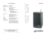
1
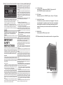
20 w atts continuous
65H z – 18kH z
101dB @ 1 m eter
W oofer
5.25" (133.35m m ) high efficiency
m agnetically shielded
1" (25m m ) dom e
1 st order passive @ 8kH z
-6dB /octave sliding low pass (3kH z to 8kH z)
T w eeter
C rossover
T one C ontrol
W ireless inputs
2 user-installable receivers
V H F (169-213M H z) – 30 fixed
U H F (794-806M H z) – 63 user-selectable
Infrared – 2 fixed
W ired inputs/output
M ic
-81dB V (0.089m V R M S ) for 1 w att
100K Ω unbalanced, ¼ " phone jack, variable
-40dB V (10m V R M S ) for 1 w att
10K Ω unbalanced, R C A jack, variable
+15dB V m ax - R C A ja ck
Line
Line-O ut
W eight
D im ensions
C om pliance
A C P o w er R equirem ents
8.5lb (3.85kg) approx. w /out receivers
12.4"H x 7.09"W x 5.6"D (315 x 1 80 x 142m m )
U L, C -U L, and F C C approved
U ser sw itchable
110-125 / 210-240V A C - 50H z / 6 0H z
Included w /speaker
R em ovable w all-m ount bracket w ith 2 screw s
and rubber anti-rotate pads, rem ovable right-angle
A C cord, 4 self-adhesive anti-skid pads, 4 m odule
screw s, 1 or 2 noise-canceling circuit boards
(depending on how m any m odule s are installed)
AZDEN Corp., P.O. Box 10, 147 New Hyde Park Road, Franklin Square, NY 11010
516.328.7500 [vox] • 516.328.7506 [fax]
[email protected] [email] • www.azdencorp.com [on the web]
- Specifications subject to change without notice 25-1002
© 2004 Azden Corp. • Printed in USA
MULTI-PURPOSE / MULTI-FUNCTION POWERED SPEAKER SYSTEM
R ated P ow er
F requency R esponse
M ax S P L @ rated output
APS 25
APS 25 SPECIFICATIONS
USER’S GUIDE
Warning: To prevent shock hazard do not open or remove speaker/speaker grill.
4. Power Cord Protection - Power supply cords should be
routed so that they are not likely to be walked on or
pinched by items placed upon or against them, paying
particular attention to cords at plugs or convenience receptacles.
5. Ventilation - A metal heatsink is provided for heat dissipation. To ensure reliable operation of the speaker and
to protect it from overheating, this heatsink most not be
blocked or covered. Do not place this speaker in a builtin installation such as a bookcase or rack unless proper
ventilation is provided.
(the lighting flash with arrowhead symbol within an 6. Wall Mounting - Mount this speaker to the wall or stand
equilateral triangle) is intended to alert the user to the only as recommended by the manufacturer.
presence of uninsulated "dangerous voltage" within
USE
the product's enclosure that may be of sufficient
1. Accessories - To avoid personal injury:
magnitude to constitute a risk of electric shock to
•Do not place this speaker on an unstable cart, stand,
persons: and
(the explanation point within an
tripod, bracket, or table. It may fall, causing serious inequilateral triangle) is intended to alert the user to the jury and serious damage to the speaker.
•Use only with a cart, stand, tripod, bracket or table
presence of important operating and maintenance
(servicing) instructions in the literature accompanying recommended for this purpose or included by the manufacturer. When using the included bracket, follow the
the product.
manufacturer’s instructions for mounting the
WARNING:
speaker.
2. Wall or Ceiling Mount - The product should be
TO PREVENT FIRE OR SHOCK HAZARD, DO NOT
mounted to the wall or ceiling only as recommended
EXPOSE THIS UNIT TO RAIN OR MOISTURE.
by the manufacturer.
CAUTION:
3. Speaker and Cart Combination - A speaker and
This powered speaker should be used with either 110-125VAC / 210cart combination should be moved with care. Quick
240VAC - 50Hz/60Hz only. DO NOT use any other power source.
stops, excessive force, and uneven surfaces may
cause the speaker and cart combination to overturn.
4. Water and Moisture - Do not use this speaker near or in
water or in an extremely moist environment.
5. Cleaning - Unplug the speaker from the wall outlet before cleaning. Do not use liquid or aerosol cleaners.
Use a damp cloth for cleaning.
6. Heat - Situate the speaker away from heat sources
such as radiators, heat registers or other heat producElectrical energy can perform many useful functions. But ing items.
improper use can result in potential electrical shock or 7. Attachments - Do not use attachments not recomfire hazards. This product has been engineered and mended by the product manufacturer as they may cause
manufactured to assure your personal safety. In order hazards.
not to defeat the built-in safeguards, observe the follow- 8. Replacement Parts - When replacement parts are required, be sure the service technician has used replaceing basic rules for its installation, use and servicing.
ment parts specified by the manufacturer or have the
same characteristics as the original part. Unauthorized
ATTENTION:
Follow and obey all warnings and instructions marked substitutions may result in fire, electric shock, or other
on your speaker and its operating instructions. For safety, hazards.
please read all the safety and operating instructions be- 9. Safety Check - Upon completion of any service or refore you operate this speaker and keep this booklet for pairs to this product, ask the service technician to preform safety checks to determine that the product is in
future reference.
proper operating condition.
10. Damage Requiring Service - Unplug this product from
INSTALLATION
1. Polarization - Your speaker equipped with a polarized the wall outlet and refer servicing to qualified service
alternating current line plug (a plug having one blade personnel under the following conditions:
a) When the power-supply cord or plug is damaged,
wider than the other). This plug will fit into the power
b) If liquid has been spilled, or objects have fallen
outlet only one way. This is a safety feature.
If you are unable to insert the plug fully into the out- into the product,
c) If the product has been exposed to rain or water,
let, try reversing the plug. If the plug should still fail to fit,
d) If the product does not operate normally by followcontact your electrician to replace your obsolete outlet.
Do not defeat the safety purpose of the polarized plug. ing the operating instructions. Adjust only those controls
2. Power Sources - Operate your speaker only from the that are covered by the operating instructions as an imtype of power indicated at the voltage selector switch on proper adjustment of other controls may result in damthe rear panel. If you are not sure of the type of power age and will often require extensive work by a qualified
supply at your site, consult with the local power com- technician to restore the product to its normal operation,
e) If the product has been dropped or damaged in
pany.
3. Overloading - Do not overload wall outlets, extension any way, and
f) When the product exhibits a distinct change in percords, or integral convenience receptacles as this can
formance - this indicates a need for service.
result in a risk of fire or electrical shock.
(5) 3-Position Switch
left position:OFF - Middle position:STANDBY - Right position:ON
In the “STANDBY” position, the audio is muted.
(6) LED Indicator
Red when the switch is in “STANDBY” position - Green in “ON” position.
(7) Audio Output Connector
This 3.5mm mono connector is where the mic is plugged in. This connector was designed to be used with a special “screw-down” connecting jack
that eliminates the possibility of the jack being accidentally pulled out. A
standard 3.5mm mono jack can also be used but will not afford the extra
protection.
(8) Metal Belt Clip
Used to attach the 32BT securely to a belt.
NOTE: Remove the battery if the transmitter is not used for a long period of time.
IMPORTANT
SAFETY
INSTRUCTIONS
AAPS 25 using wall-mount bracket
page 9
(7) Level:
Turn clockwise to increase, or counterclockwise to decrease the input level.
A small screwdriver is supplied to make adjustments. The level control is
factory-preset in the center position.
NOTE: Remove the battery if the transmitter will not be used for a long period of
time.
32BT Body-pack transmitter with lavalier microphone:
Introduction
Congratulations. You have chosen one of the most versatile powered
loudspeaker systems on the market today. The Azden® APS 25 is a sophisticated 4-channel mixable speaker system that allows you to utilize
two different wireless inputs in addition to a wired microphone and a linelevel input - all at the same time if needed. The master, front mounted,
volume knob controls the overall level of all four inputs simultaneously.
Housed in a high-impact polycarbonate cabinet, the APS 25 can be
wall mounted using the included bracket, stand-mounted or simply placed
wherever needed. The Auto On/Off circuitry makes using the APS 25
simple and convenient.
To get the most from your new APS 25 Speaker System be sure to
carefully read this user’s guide, paying particular attention to the receiver
module(s) installed and the transmitter(s) you’ve chosen.
Again, congratulations, and thanks for choosing Azden®.
Contents
(1) Open the battery compartment lid by sliding it in the direction indicated
and raising it.
(2) Insert one fresh Alkaline 9-volt battery into the compartment. Make sure
battery polarity is correct.
(3) Frequency Label
The Frequency label indicates what frequency (in MHz) the transmitter
broadcasts on. The AZDEN receiver in use must also be on the same
frequency.
Cautions and Safety Information
Introduction
APS 25 rear panel diagrams
Installing an APS module
APS 25 inputs/output and controls
Mounting the APS 25
Using APS VR module and VHF transmitters
Specifications
inside front cover
page 1
page 2
page 3
page 3-4
page 4
page 5-9
back cover
(4) Audio Input Level Control
Turn clockwise to increase, or counterclockwise to decrease the input
level. A small screwdriver is supplied to make adjustments. The level
control is factory-preset in the center position.
page 8
AAPS VR VHF receiver module
page 1
31XT Plug-in transmitter adaptor:
Note:The 31XT is designed to turn any wired dynamic metal-body microphone
that has an XLR output into a wireless microphone.
1
Connecting the 31XT:
Disconnect the microphone cable from the microphone by pushing down on the
release button where the microphone and cable connect. Connect the 31XT by
lining up the pins on the microphone with the holes on the transmitter, and insert.
Push the 31XT into the microphone until it locks into place.
Removing the 31XT:
Push down on the release button and pull out.
3
2
5
7
4
(1) Turn the bottom half of the case counterclockwise until it is completely off.
8
6
11
9
(2) Insert one fresh alkaline “AA” battery into the compartment. Make sure
battery polarity is correct. Replace the bottom half of the case and turn
clockwise until snug. DO NOT OVERTIGHTEN.
(3) Frequency Label:
The frequency label indicates what frequency (in MHz) the transmitter broadcasts on. The AZDEN receiver in use must also be on the same frequency.
12
10
B
A
C
(4) Power Off/On:Switches the transmitter off or on.
(5) Audio Off/On:
Slide the switch to “On” for normal operation. Slide it to “Off” to mute the
audio.
NOTE: When turning the transmitter on, slide the Power “On” first, and then slide
the Audio to “On”. When turning the transmitter off, first slide the Audio to “Off”.
(6) LED:
RED when Power is “On” and Audio is “Off”. GREEN when Power and Audio
are both “On”.
page 2
page 7
(6) 3-Position Switch
Left position:OFF - Middle position:STANDBY - Right position:ON
In the “STANDBY” position, the audio is muted.
(7) LED Indicator
RED when switch is in “STANDBY” position - GREEN in “ON” position.
NOTE: Remove the battery if the transmitter will not be used for a long period of
time.
31HT Handheld Microphone Transmitter:
(1) Turn the bottom half of the microphone case counterclockwise until it is
completely off.
(2) Insert one fresh Alkaline “AA” battery into the compartment. Make sure battery polarity is correct. Then replace bottom half of microphone case and
turn clockwise until snug. DO NOT OVERTIGHTEN.
(3) The frequency label indicates what frequency (in MHz) the transmitter broadcasts on. The AZDEN receiver in use must be on the same frequency.
(4) 3-Position Switch
Bottom position:OFF - Middle position:STANDBY - Top position:ON
In the “STANDBY” position, the audio is muted.
(5) LED indicator
RED when the switch is in “STANDBY” position - GREEN in “ON” position.
NOTE: Remove the battery if the transmitter is not used for a long period of time.
page 6
Installing an APS module... (see photo - page 1)
All APS modules install into the APS 25 in the same manner. To
install, first remove the blank panel by loosening the two retaining thumb
screws. Next remove the “shorting board” by pulling it straight out. Now,
simply slide the module into the slot and lightly press until the connector
in the rear engages and the front panel is flush. Last, replace the two
thumb screws and tighten snugly. Any APS module can be inserted into
either slot. Save the “shorting board(s)” for possible later use.
NOTE: If you purchased your APS 25 with one or two modules, they
have already been installed.
The APS 25 Inputs/Outputs and Controls...
A. MASTER VOLUME CONTROL - controls the overall volume of the
APS 25 as well as the LINE OUT (8) connector.
B. TONE - this is a variable frequency high-cut tone control that is primarily used to reduce high-frequency feedback. The control is
essentially flat when turned fully clockwise and reduces more high
frequencies as it is rotated counterclockwise.
C. LED - displays the power state of the speaker. See (4) for details.
1. CHAN A slot - any module can be installed here.
2. CHAN B slot - any module can be installed here.
3. MIC INPUT - plug a wired dynamic microphone in here. This 1/4 inch
jack is designed to accept a low impedance microphone. The input
volume is controlled by the MICROPHONE LEVEL knob (5).
4. OFF/AUTO/ON switch - this controls the power for the speaker after
the MASTER AC SWITCH (12) is placed in the ON position.
• The speaker is essentially OFF with this switch in the OFF position.
The front panel LED (C) will glow Red.
• The speaker will come ON from its standby mode automatically when
any signal is sensed when the switch is in the AUTO position. The
LED (C) will turn from Red to Green. 10 minutes after all audio stops
the speaker will return to its standby mode and the LED (C) will return to Red.
• The speaker is ON at all times when the switch is in the ON position.
The LED (C) will glow Green.
5. MIC LEVEL - this knob controls the input volume of the microphone
plugged into the MIC INPUT (3). It is always good practice to leave
the control turned all the way down (full counterclockwise) when no
microphone is being used.
6. LINE LEVEL - this knob controls the input volume of anything plugged
into the LINE IN (7) jack.
page 3
7.
LINE IN - this mono RCA jack is designed to accept audio from
devices such as CD players, video tape players or anything else with
a line-level audio output. The input volume is controlled by the LINE
LEVEL knob (6).
8. LINE OUT - this mono RCA jack provides line-level audio to drive
additional speakers or other audio devices with a line-level input.
The level is controlled by the MASTER VOLUME CONTROL (A) on
the front panel. If this output is used to drive the LINE IN (7) of a
second APS 25, the MASTER VOLUME CONTROL (A) will control
the overall volume of both speakers.
9. AC JACK - this is where the removable AC plug is attached to the
speaker. The AC plug is polarized and will only attach one way.
10. AC FUSE - the replaceable AC fuse is housed here. Follow the marking on the panel for proper replacement if needed (0.5A for 210240VAC use or 1.0A for 110-125VAC use).
11. AC VOLTAGE SELECTOR - set down when used with 110-125VAC
(US and other areas) and up when used with 210-240VAC (Europe
and other areas). Be sure to check your local voltage before adjusting the selector. The speaker is shipped from the factory set in the
110-125VAC position and with a cable designed for that voltage.
Mounting the APS 25
• Wall Mounting (see photo - page 9)
The APS 25 is supplied with a wall mounting bracket. It can be attached to the speaker via the built-in 1/4" X 20 threaded holes on the top
and bottom of the speaker using the included large screws. Supplied
rubber pads can be applied to the inside surface of the bracket to protect
the speaker surface from scratching and reduce the possibility of the
speaker rotating in the bracket. The bracket can be attached to the desired surface using a number of different fasteners. Be sure to use fasteners that are appropriate for the surface you are mounting to and that can
support the speaker’s weight. Once the desired position is achieved, tighten
the screws securely.
• Stand Mounting
The APS 25 has two industry-standard 5/8" x 27 threaded inserts moulded into the cabinet - one on the bottom and one on the side. These allow
the speaker to be securely mounted to a stand (such as a microphone
stand). Be sure to tighten the speaker securely to the stand. Also, be sure
that the stand can support the weight of the speaker and that it will be
stable with that weight attached.
• Flat surface
Four self-adhesive anti-skid pads can be applied to the bottom or side
of the speaker to help stop it from moving when placed on a flat surface.
page 4
Using an APS VR module and VHF Transmitter(s)...
The APS VR receiver module comes pre-adjusted to one of 30 different VHF frequencies between 169MHz and 213MHz. The particular
frequency(s) you have were chosen to not interact/interfere with TV stations in your area. After installing the module (page 2) you will have to
attach the antenna and position it as close to vertical as possible. The
volume control on the module adjusts the input volume of that particular
module. Try to keep it set near its mid point for best performance.
Transmitters...
Model 31LT: Lavalier microphone with body-pack transmitter. Ideal for speaking
applications such as Lecturers, Actors, Actresses, etc.
(1) Open the battery compartment lid by sliding it down and raising it.
(2) Insert one fresh Alkaline 9-volt battery into the compartment. Make sure the
battery polarity is correct.
(3) Frequency Label
The Frequency label indicates what frequency (in MHz) the transmitter broad
casts on. The AZDEN receiver in use must also be on the same frequency.
(4) 31LT lavalier mic:
Clips onto a tie, lapel, etc. The transmitter’s cable doubles as an antenna.
Extend the cable as much as possible for the best performance.
(5) Audio Input Level Control
Turn clockwise to increase, or counter-clockwise to decrease the input level.
A small screwdriver is supplied to make adjustments. The level control is
factory-preset in the center position.
page 5