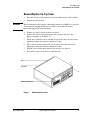
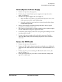
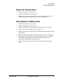
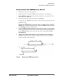
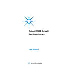
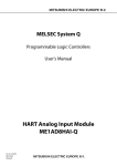
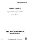
1
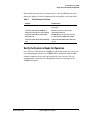
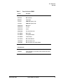
Agilent 35900E Dual Channel Interface
Service Manual
35900E Dual Channel Interface
Agilent 35900E Service Manual
© Agilent Technologies 1994–2000
Electrical Shock Hazard
Safety Symbols
All Rights Reserved. Reproduction,
adaptation, or translation without
permission is prohibited, except as
allowed under the copyright laws.
WARNING
CAUTION
A caution calls attention to a condition
or possible situation that could damage
or destroy the product or the user’s
work.
Part number 35900-90417
First Edition, MAY 2000
Replaces Part No. 35900-90410,
Operating and Service Manual.
HP® is a registered trademark of
Hewlett-Packard Co.
Printed in USA
Agilent Technologies, Inc.
2850 Centerville Road
Wilmington, DE 19808-1610
USA
This product is a Safety Class 1
instrument (provided with a protective
earth terminal). To avoid electrical
shock, the instrument must be
connected to the AC power supply mains
through a three-conductor power cord,
with the third wire firmly connected to
an electrical ground (safety ground) at
the power outlet. Any interruption of the
protective (grounding) conductor or
disconnection of the protective earth
terminal, under a fault condition could
cause a shock, that could result in
personal injury.
WARNING
A warning calls attention to a condition
or possible situation that could cause
injury to the user.
Contents
Chapter 1: Introduction
Manual Overview ....................................................................................................... 6
Chapter 2:
Troubleshooting the 35900E
Verify the 35900E is Ready for Operation .............................................................. 8
In Case of Difficulty .................................................................................................. 8
Possible Causes for Failure............................................................................... 9
Verify the System is Ready for Operation .............................................................. 9
Chapter 3: Parts Replacement
Overview .................................................................................................................. 11
Parts List for the 35900E ................................................................................. 12
Remove/Replace the Top Cover ............................................................................ 13
Remove/Replace the Front Panel .......................................................................... 14
Remove/Replace the Power Supply ...................................................................... 15
Remove the MIO Bracket ....................................................................................... 15
Remove the Connector Board ............................................................................... 16
Remove/Replace the Mother Board ...................................................................... 16
Remove/Install the SIMM Memory Boards .......................................................... 17
Chapter 4: Instrument Parts Breakdown
Parts Breakdown—Figure 4 .................................................................................. 19
Parts Breakdown—Figure 5 .................................................................................. 21
Released: MAY 2000
Agilent 35900E Service Manual
4
1
Introduction
Released: MAY 2000
Agilent 35900E Service Manual
5
Introduction
Manual Overview
Introduction
The Agilent 35900E Dual Channel Interface Service Manual provides step-bystep instructions for removing and replacing various parts in your 35900E Dual
Channel Interface. Refer to Chapter 3: Parts Replacement for parts
identification.
For operating directions, see the Agilent 35900E Dual Channel Interface
Users Manual.
Caution
The 35900E contains parts that are sensitive to electrostatic discharge. Wear an
ESD wrist strap during all assembly and disassembly procedures.
Manual Overview
This manual contains four chapters.
Chapter 1: Introduction, provides the purposes of this manual and an
overview of its contents.
Chapter 2: Troubleshooting the 35900E, provides a troubleshooting
checklist, an explanation of the LEDs, and a recommendation for use of DEMO
chromatograms.
Chapter 3: Parts Replacement, provides a description of how to remove
each part from the 35900E Dual Channel Interface.
Chapter 4: Instrument Parts Breakdown, provides part numbers and
illustrations of each part in the 35900E Dual Channel Interface.
Released: MAY 2000
Agilent 35900E Service Manual
6
2
Troubleshooting the 35900E
Released: MAY 2000
Agilent 35900E Service Manual
7
Troubleshooting the 35900E
Verify the 35900E is Ready for Operation
Troubleshooting the 35900E
Verify the 35900E is Ready for Operation
At power up, the 35900E automatically executes internal self-tests to determine
the amount of memory installed and to verify that the main power, system
memory, and the MIO communication interface, and other internal circuits are
operating properly. These tests take about 30 seconds for a 1-MByte system.
The FAULT light will blink ON/OFF during this time.
When the 35900E has completed the internal self-tests, verify that:
1.
the FAULT lamp is OFF
2.
the POWER indicator is ON
3.
no other indicators are blinking
In Case of Difficulty
If the 35900E does not power up correctly, turn power off and check the
following:
1.
Rear panel configuration switches 3 through 6 are DOWN (for normal
operation).
2.
MIO card is correctly configured for host computer communications.
3.
MIO card is connected to host computer or network.
4.
Analog signal cables are connected.
5.
Remote control cables are connected (if needed).
6.
Digital I/O cables are connected (if needed).
7.
Power cord is connected.
Released: MAY 2000
Agilent 35900E Service Manual
8
Troubleshooting the 35900E
Verify the System is Ready for Operation
If the problem persists after cycling the power, note the LED pattern on the
front panel display. Check the following table for possible causes for failure.
Table 1.
Possible Causes for Failure
Condition
Possible Causes
POWER light is OFF
Power cord is disconnected or problem with the
power supply
FAULT light remains ON and COMM light is
flashing (note: other lights may also be flashing)
MIO card may be loose or there may be a
problem with the MIO card
FAULT light remains ON and Channel B NOT
READY light is ON
No SIMM module in the front slot or there may
be a problem with the SIMM module installed
FAULT light remains ON and Channel B RUN light
is ON
Problem found with SIMM module installed in the
rear slot
Verify the System is Ready for Operation
Once you have verified that the 35900E is ready for operation, you can use the
test chromatogram stored in the 35900E ROM in conjunction with the Host
computer software to check the operation of the entire system. The test
chromatogram is turned on via configuration switches 3 through 6 on the
35900E’s back panel.
Released: MAY 2000
Agilent 35900E Service Manual
9
3
Parts Replacement
Released: MAY 2000
Agilent 35900E Service Manual
10
Parts Replacement
Overview
Parts Replacement
Overview
This chapter provides a description of how to remove and replace each of the
major components from the 35900E Dual Channel Interface. Since the 35900E
repair strategy is only to the board or subassembly level, more detailed
information is not needed.
See Chapter 4 for an illustrated parts breakdown.
The 35900E has been designed for easy assembly and disassembly of all the
replaceable modules. The only tool needed for this process is a Pozidriv®
screwdriver No. 2 Pt (Part No. 8710-0900).
All electronic assemblies and parts should be handled with proper ESD
procedures. This means that the parts should be packed in conductive
packaging material and, when not in this packaging, should be placed only on a
static-free surface. Anyone handling these items should be properly grounded
through a wrist strap that has a common ground with the static-free work
surface.
The following table lists all of the assembly part numbers for the 35900E.
Released: MAY 2000
Agilent 35900E Service Manual
11
Parts Replacement
Overview
Table 2.
Parts List for the 35900E
Part No.
Description
0403-0102
Mother Board Guides
0403-0166
MIO Card Guides
0950-2557
Power Supply
1818-4271
SIMM Memory Board, 1 MB
1818-5222
SIMM Memory Board, 4 MB
35900-00160
MIO Bracket
35900-00180
Top Cover
35900-00190
Chassis
35900-60890
Front Panel (Front Cover)
G1279-60010
Mother Board
G1279-69010
Exchange Mother Board
G1279-60020
Connector Board
G1241-60010
MIO Card-GPIB/RS-232
J2552-69013
MIO Card-JetDirect Card
J4100-69001
MIO Card-JetDirect Card 10/100 10Base2
Assorted Screws
Released: MAY 2000
0515-1040
Screw, M4 x 8 Pozidriv, panhead, SS with external tooth lockwasher
2360-0544
Screw, 6-32 UNC-2A .375 inch long, Pozidriv, panhead, with external
tooth lockwasher
Agilent 35900E Service Manual
12
Parts Replacement
Remove/Replace the Top Cover
Remove/Replace the Top Cover
WARNING
1.
Place the unit on a table so that the back is visible to you (cables visible).
2.
Remove the power cord.
When removing or replacing the subassembly inside the 35900E, be certain the
AC line cord is unplugged from the rear of the unit in order to avoid a
potentially dangerous electrical shock.
3.
Remove any cables attached to the rear panel.
4.
Remove the two screws attaching the cover to the rear panel. (See
Figure 1 and part "A" of Figure 4.)
5.
Lift up the back of the cover and slide the lip of the cover over the frame,
slipping the front tabs under the front panel edge.
6.
When you are ready to replace the cover, fit the cover over the frame,
slipping the front tabs under the front panel edge.
7.
Push the cover firmly down until the screw holes are aligned.
8.
Reattach the two screws on the back of the unit.
Lip
Front Panel
Power Cord Connection
Figure 1.
Released: MAY 2000
Removing the top cover.
Agilent 35900E Service Manual
13
Parts Replacement
Remove/Replace the Front Panel
Remove/Replace the Front Panel
1.
Remove the top cover. (See Figure 1.)
2.
Disconnect the front panel connector from the mother board by pressing
down on the two latches on the end of the connector on the mother board
and lifting the connector straight up. (See Figure 2)
3.
Remove the four screws holding the front panel to the unit.
4.
Gently pull the front panel forward until it is detached from the frame.
5.
Remove the ground wire connection (green wire) from the ground clip by
pulling it firmly.
6.
When you are ready to replace the front panel, reattach the green ground
wire to the ground clip on the chassis.
7.
Fit the bottom lip of the front panel under the lip of the frame and push it
against the frame, fitting the power switch into the hole.
8.
Connect the front panel cable to the connector, pressing firmly until the
ears of the connector lock over the ends of the black connector.
9.
Replace the four screws, two on each side.
Disconnect front panel
cable from connector
Ground Clip
Disconnect ground wire
from ground clip
Remove 4 screws
Figure 2.
Released: MAY 2000
Removing the front panel.
Agilent 35900E Service Manual
14
Parts Replacement
Remove/Replace the Power Supply
Remove/Replace the Power Supply
1.
Remove the top cover. (See page 13.)
2.
Remove the screw attaching the power supply to the right side of the
frame. (See Figure 4.)
3.
Disconnect the power supply cable. (See Figure 5.)
a.
Slide a flat-blade screwdriver (or your thumb nail) between the back
of the connector and the white locking ridge.
b.
Grasp the ends of the connector between your thumb and forefinger
and pull firmly upwards.
4.
Pull the power supply unit forward to slip it off of the tabs, then pull
upwards to remove it from the frame.
5.
When you are ready to replace the power supply, fit the new power supply
over the hooked tabs and press it against the frame.
6.
Reattach the power supply to the frame by replacing the holding screw on
the right side of the unit.
7.
Reconnect the power supply cable to the white connector. Push the
connector down firmly, until the locking ridge fits over the back of the
connector.
Remove the MIO Bracket
1.
Remove the top cover. (See page 13.)
2.
Remove the MIO card by first removing the two thumb screws holding the
card at the back of the unit. The card can then be pulled out from the rear
plate.
3.
Remove the three screws attaching the MIO bracket to the frame. (See
part "A" in Figure 5.)
4.
Firmly pull up on both the plate and the connector board, holding them
together at a right angle.
Released: MAY 2000
Agilent 35900E Service Manual
15
Parts Replacement
Remove the Connector Board
Remove the Connector Board
1.
Remove the top cover. (See page 13.)
2.
Remove the MIO bracket. (See page 13.)
3.
Remove the two screws attaching the connector board to the plate. The
board will separate from the plate. (See part "A" in Figure 5.)
Remove/Replace the Mother Board
1.
Remove the top cover. (See page 13.)
2.
Remove the front panel. (See page 14.)
3.
Remove the MIO bracket and connector board. (See page 15 and 16.)
4.
Disconnect the power supply cable. (See page 15.)
5.
Remove the two screws attaching the mother board to the back of the unit.
(See Figure 5.)
6.
Slide the mother board out the front of the unit. (See part "4" in Figure 5)
7.
When you are ready to replace the mother board, slide the new mother
board into the guides from the front of the unit so that the cable
connections fit through the back of the unit.
8.
Replace the two screws on the back of the unit and all other removed
parts.
Released: MAY 2000
Agilent 35900E Service Manual
16
Parts Replacement
Remove/Install the SIMM Memory Boards
Remove/Install the SIMM Memory Boards
1.
Remove the top cover. (See page 13)
2.
Push out on the metal tabs holding the board in place. (See Figure 3)
3.
Tilt the SIMM memory board towards the front of the unit about 45° and
slide it out. (See Figure 3)
4.
If installed, repeat the process for the second SIMM.
If using only one SlMM board, it must be installed in the slot closest to the
front of the unit.
If using two SIMM boards, the front slot must be empty in order to install a
SIMM in the rear slot. Therefore, when using two SIMM boards, install the
rear SIMM first and then the front one.
5.
Seat the SIMM memory board in the slot so that the posts are aligned with
the holes in the upper corners of the board and the memory chips mounted
on the SIMM board face the rear of the unit. (The board will be slightly
tilted forward.)
6.
Push the board backwards until the metal tabs slip over the ends of the
SIMM board and the white posts fit through the holes. The board will be
seated vertically in the connector.
Tabs
Front of Unit
Figure 3.
Released: MAY 2000
Removing the SIMM memory board.
Agilent 35900E Service Manual
17
4
Instrument Parts Breakdown
Released: MAY 2000
Agilent 35900E Service Manual
18
Instrument Parts Breakdown
Parts Breakdown—Figure 4
Instrument Parts Breakdown
Parts Breakdown—Figure 4
Item No.
Description
Part No.
Qty
1
Top Cover
35900-00180
1
2
MIO Card-GPIB/RS-232
Gl241-60010
1
3
MIO Bracket
35900-00160
1
4
Power Supply
0950-2557
1
5
Front Panel (Front Cover)
35900-60890
1
6
MIO Card Guides
0403-0166
2
7
Chassis
35900-00190
1
Assorted Screws
Released: MAY 2000
A
Screws, M4 x 8 Pozidriv, panhead, SS with
external tooth lockwasher
0515-1040
6
B
Screw 6-32 UNC-2A .375 inch long, Pozidriv,
panhead, with external tooth lockwasher
2360-0544
1
Agilent 35900E Service Manual
19
Instrument Parts Breakdown
Parts Breakdown—Figure 4
A
1
A
2
3
6
4
A
A
7
Ground Clip
Power supply
Cable
5
Ground Wire
B
A
Front Panel
Connector
Front Panel Cable
Figure 4.
Released: MAY 2000
Agilent 35900E Service Manual
20
Instrument Parts Breakdown
Parts Breakdown—Figure 5
Parts Breakdown—Figure 5
Item No.
Description
Part No.
Qty
1
Power Supply
0950-2557
1
2
MIO Bracket
35900-00160
1
3
Connector Board
G1279-60020
1
4
Mother Board
G1279-60010
1
Exchange
G1279-69010
SIMM Memory Board, 1 MB
1818-4271
1
SIMM Memory Board, 4 MB (optional)
1818-5222
2
Mother Board Guides
0403-0102
2
0515-1040
7
5
6
Assorted Screws
A
Released: MAY 2000
Screws M4 x 8 Pozidriv, panhead, SS
with external tooth lockwasher
Agilent 35900E Service Manual
21
Instrument Parts Breakdown
Parts Breakdown—Figure 5
1
Power Supply Cable
A
A
A
2
3
A
5
4
6
Power Supply
Mounting Tabs
Locking
Metal Tabs
Front Panel
Connector
Power Supply Connector/
Locking Ridge
Figure 5.
Released: MAY 2000
Agilent 35900E Service Manual
22