1
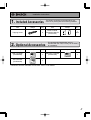
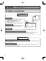
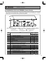
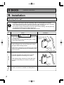
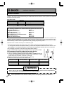
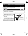
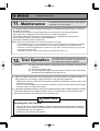
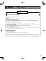
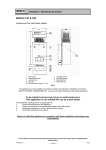
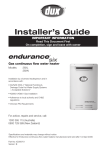
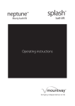
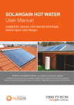
Installation Instructions
Installation Manual
Bosch Eco26+
External Model
BC2600RA
To be installed and serviced only
by an authorised person
This appliance is not suitable for
use as a pool heater
The "authorised installing person" is
responsible for:
1. Correct commissioning of this
appliance.
2. Ensure unit performs to the
specifications stated on the
rating label.
3. Demonstrate operation of unit to
customer before leaving.
4. Hand these instructions to
customer.
This appliance must be installed in accordance with the manufacturer's
installation instructions, AS5601, AS/NZS3500.4, AS3000 wiring regulations
and all Local Building, Water and Gas fitting regulations.
Failure to install this appliance in accordance with these installation
instructions may void warranty
Service Department: 1300 30 70 37
www.bosch.com.au
SAR8854
Rev. 07/08
In the interest of continued product improvement, Bosch reserves the
right to alter these specifications without notice.
*SAR8854 C*
Installation Instructions
Installation Manual
Robert Bosch
(Australia) Pty. Ltd.
CONDENSING GAS WATER HEATER
Bosch Eco26+ <BC2600RA> (Outdoor Installation)
Potential dangers from accidents during installation and use are divided into the following three
categories. Closely observe these warnings, they are critical to your safety.
DANGER
WARNING
CAUTION
DANGER indicates an imminently hazardous situation which,
if not avoided, will result in death or serious injury.
WARNING indicates a potentially hazardous situation which,
if not avoided, could result in death or serious injury.
CAUTION indicates a potentially hazardous situation which,
if not avoided, may result in minor or moderate injury.
WARNING: If the information in this manual is not followed exactly, a fire or explosion may result
causing property damage, personal injury or death.
Prohibited
Disconnect
Power
Earth
Be sure to do
CAUTION
Requests to Installers
• In order to use the water heater safely, read this installation manual carefully, and follow the
installation instructions.
• Failures and damage caused by erroneous work or work not as instructed in this manual are not
covered by the warranty.
• Check that the installation was done properly in accordance with this Installation Manual upon
completion.
• After completing installation, please either place this Installation Manual in a plastic pouch and
attach it to the side of the water heater, or hand it to the customer to retain for future reference.
2
Installation Instructions
1. Included Accessories
Part
Shape
Tapping Screw
Q’ty
Part
5
Owner's Guide,
Installation Manual
(this document)
2. Optional Accessories
Part
Shape
Priority
Burner on
Part
1
Bathroom Controller
(YPRS67XB)
Q’ty
1
each
Shape
Q’ty
Bathroom Controller
Bath Fill
Temp.
ON/OFF
Set Time
Volume
setting
Bath Fill
Press 2sec.
to set time
YPRM67XB
Shape
The accessories listed below are not
included with the units, but may be necessary
for installation.
Q’ty
Main Controller
Main Controller
(YPRM67XB)
The following accessories are included with the unit.
Check for any missing items before starting installation.
Priority
Burner on
Bath Fill
Temp.
ON/OFF
Call
Priority
Bath Fill
1
YPRS67XB
Sub Controller
Sub Controller
(YPRP62XB)
ON/OFF
Hot Water Temp
Priority
Burner on
1
Call
YPRP62XB
Hot Water Temp.
• Maximum two Sub controllers can be used. See P.14 for details.
3
Installation Instructions
3. Before Installation
WARNING
Check the Gas
• Check that the data plate (located inside of front cover) or
a temporary label (located on the front cover)
For NG Gas
indicates the correct type of gas.
• Check that the gas supply line is sized for
178 MJ/hr for this unit.
• DO NOT OPERATE WITH ANY OTHER GAS TYPE.
MODEL BC2600RA
Check the Power
• The power supply required is 240/230VAC, at 50Hz.
Using the incorrect voltage may result in fire or
electric shock.
GAS TYPE
: NG
GAS CONSUMPTION
: 178MJ/hr
HEAT OUTPUT
: 45.7kW
ELECTRICAL RATING
: AC240/230V 50Hz
RATED POWER
: 56.0W
HOT WATER SUPPLY CAPACITY
: 26L/min RAISED 25°C
GAS PRESSURE TEST POINT
: MAX : 0.73kPa
: M I N : 0.18kPa
GAS SUPPLY PRESSURE
MAX 3 0kP
Warning labels
• Located on the right side of the casing -PLEASE READ THESE LABELS CAREFULLY!
Use Extreme Caution if Using With a Solar Pre-Heater
• A solar transfer valve must be installed with all solar applications when using Bosch Eco 26+.
• Solar systems installed without a solar transfer valve will void all Bosch warranty.
CAUTION
Do Not Use Equipment for Purposes Other Than Those Specified
• Do not use for other than increasing the temperature of the water supply, as unexpected accidents
may occur as a result.
Check Water Supply Quality
• If the water supply is hard, acidic or otherwise impure, treat the water with approved methods in
order to ensure full warranty coverage.
4
Installation Instructions
4. Choosing Installation Site
* Locate the appliance in an area where water leakage from the unit or connections will not result in
damage to the area adjacent to the appliance or to the lower floors of the structure. When such
locations cannot be avoided, it is recommended that a suitable drain pan, adequately drained, be
installed under the appliance. The pan must not restrict combustion air flow.
DANGER
• This water heater is for outdoor installation only.
Never install it indoors.
Do not enclose the termination with corrugated
metal or other materials.
This will cause carbon monoxide
poisoning and a potential fire
hazard.
Indoor
WARNING
• Avoid places where fires are common, such as those where petrol,
benzene and adhesives are handled, or places in which corrosive gases
(ammonia, chlorine, sulfur, ethylene compounds, acids) are present.
May result in fire.
Prohibited
• Avoid installation in places where dust or debris will accumulate.
Dust may block the air-supply opening, causing the performance of the
device fan to drop and incomplete combustion to occur as a result.
• Avoid installation in places where special chemical agents
(e.g., hair spray or spray detergent) are used.
Ignition failures and malfunction may occur as a result.
• Carbon Monoxide Poisoning Hazard. Do not install this water heater in a
mobile home, recreation vehicle or on a boat.
5
Installation Instructions
CAUTION
• Install the water heater in a location where it is free from obstacles and
stagnant air.
• Consult with the customer concerning the location of installation.
• Do not install the water heater near staircases or emergency exits.
• Do not install the water heater where the exhaust will blow on outer
walls or material not resistant to heat. Also consider the surrounding
trees and animals.
The heat and moisture from the water heater may cause discoloration of
walls and resinous materials, or corrosion of aluminium materials.
• Do not locate the vent termination directed towards a window or any
other structure which has glass or wired glass facing the termination.
Prohibited
• Install in a location where the exhaust gas flow will not be affected by
fans or range hoods.
• Take care that noise and exhaust gas will not affect neighbours.
• Avoid installation where the unit will be exposed to excessive winds.
• Before installing, make sure that the vent termination will have the proper
clearances according to AS5601, or your local authority.
• On combustible surfaces e.g. weatherboards etc. it is not required to
install a fire proof back board.
5. Installation Clearances
WARNING
Before installing, check for the following:
The location of the flue terminal must comply with the clearances shown on this page. If you are
unsure about clearances not indicated here, in general refer to AS5601, or your local authority. In
Western Australia refer to the WA Office of Energy rules and regulations.
Flue outlet must be free from any combustible material.
6
Installation Instructions
CLEARANCES FOR FLUE TERMINAL (front of heater)
The location of the flue terminal must comply with the clearances shown on this page. If you are unsure
about clearances not indicated here, in general refer to AS5601, or your local authority. In Western
Australia refer to the WA Office of Energy rules and regulations.
a
j
W
f
n
j
h
door
k
h
h
T
I
c
c
T
j
g
k
e
e
d
P
g
d
M
b
T
Use as a guide only. Refer to AS5601 or local gas fitting rules for specific locations
T=Flue terminal
I=Mechanical air inlet
Ref
M=Gas meter
P=Electricity meter
or fuse box
Item
Shaded area indicates
prohibited area
W=Window
Minimum
Natural
draft
a
b
c
d
e
f
g
h
j
k
n
Below eaves,balconies and other projections
Appliancesup to 50MJ/h input
300
Appliancesover 50 MJ/h input
500
From the ground, above a balcony or other surface
300
From a return wall or external corner
500
From a gas meter
1000
From an electricity meter or fuse box (P)
500
From a drain pipe or soil pipe
150
Horizontally from any building structure or obstruction facing a flue
500
terminal
From any other flue terminal, cowl, or combustion air intake
500
Horizontally from an opening window, door, non-mechanicalair inlet. Or other opening
into a building with the exception of sub floor ventilation
Appliancesup to 150 MJ/h
500
Appliancesover 150MJ/h input up to 200 MJ/h input
1500
Appliances over 200 MJ/h input up to 250 MJ/h input
1500
Appliances over 250 MJ/h input
1500
All fan assistedflue appliancesin the direction of discharge
From a mechanicalair inlet, including spa blower
1500
Vertically below an openable window, non-mechanicalair inlet, or any other opening into a
building with the exception of sub-floor ventilation:
Spaceheaters up to 50 MJ/h
150
Other appliancesup to 50 MJ/h
500
Appliancesover 50 MJ/h and up to 150 MJ/h input
1000
Appliancesover 150 MJ/h input
1500
Clearance
mm
Fan
assisted
200
300
300
300
1000
500
75
500
300
300
300
500
1500
1500
1000
150
500
1000
1500
7
Installation Instructions
6. Installation
Securing to the wall
Be sure to do
Item
• Installation must conform with all local building, water or Gas Regulations or AS5601.
• The weight of the device will be applied to the wall. If the strength of the wall is not sufficient, reinforcement must be done to prevent the transfer of vibration.
• Do not drop or apply unnecessary force to the device when installing. Internal parts may
be damaged and may become highly dangerous.
• Install the unit on a vertical wall and ensure that it is level.
Check
Locating Screw Holes
CAUTION
• When installing with bare hands, take caution to
not inflict injury.
• Be careful not to hit electrical wiring, gas, or water
piping while drilling holes.
Mounting
Mounting Bracket
(upper)
2. Insert and tighten the screw and hang the unit by
the upper wall mounting bracket.
4. Drill holes for the remaining four screws.
Structure
Location of Screw Hole
1. Drill a single screw hole, making sure to hit a stud.
3. Determine the positions for the remaining four screws
(two for the top bracket and two for the bottom), and
remove the unit.
8
Illustration
5. Hang the unit again by the first screw, and then
insert and tighten the remaining four screws.
6. Take waterproofing measures so that water does
not enter the building from screws mounting the
device.
• Make sure the unit is installed securely so that it will
not fall or move due to vibrations or earthquakes.
Locating Screw Holes
Tapping Screw
Installation Instructions
7. Gas Piping
Follow the instructions from the gas supplier.
The appliance must be disconnected from the gas supply piping system during any pressure testing of
that system at test pressures in excess of 3.5 kPa.
The appliance and its gas connections must be leak tested before placing the appliance in operation.
The inlet gas pressure must be within the range specified. This is for the purposes of input adjustment.
In order to choose the proper size for the gas line, consult local codes and / or the AS5601.
Gas Pressure
Size the gas line according to total MJ/h
demand of the building and length from
the meter or regulator so that the following supply pressures are available even
at maximum demand refer AS5601:
Natural Gas Supply Pressure
Min. 1.13 kPa
Max. 3.00 kPa
LP Gas Supply Pressure
Min. 2.75 kPa
Max. 3.50 kPa
Gas Meter
Select a gas meter capable of supplying
the entire MJ/h demand of all gas appliances in the building.
Gas Connection
1) Fit a union to the water heater gas inlet for easy connection and removal. The thread diameter is 20 mm.
THIS DOES NOT INDICATE THE SIZE OF THE GAS
SUPPLY.
2) Fit an AGA / NZGA approved isolating gas cock in the
supply line adjacent to the water heater gas connection.
3) Ensure that the supply pipe and the gas pressure regulator (LPG or Natural Gas) has sufficient flow capacity for
this and other appliances connected to the fitting line.
4) For LPG appliances ensure that gas cylinders are of sufficient size. The water heater alone will require 2 x 45 Kg
capacity cylinders.
5) Before connecting the appliance to the gas service,
purge any debris or air from the gas service.
6) Check all joints for leaks with an approved leak tester
after connection.
Measuring Gas Pressure
In order to check the gas supply pressure to the unit, a tap is
provided on the gas inlet. Remove the hex head philips screw from
the tap, and connect a manometer using a silicon tube.
In order to check the gas manifold pressure on the gas valve inside
the unit. The pressure can be checked by removing the hex head
philips screw and connecting a manometer with a silicon tube.
Refer to AS 5601 Installation Code or NZS 5261 : 2003 installation code for pipe sizing and details.
Ensure that the gas pipe size is correct. If undersized the appliance will not operate correctly
SERVICE CALLS ARE CHARGEABLE FOR UNITS WITH INCORRECT PIPE SIZES OR BLOCKED GAS OR
WATER FILTERS.
9
Installation Instructions
8. Water Piping
Installation and service must be performed
by a qualified plumber.
Observe all applicable codes.
This appliance is suitable for potable water applications. Do not use this appliance if any part has been underwater.
Immediately call a qualified service technician to inspect the appliance and replace any part of the control system and
gas control which has been under water.
Piping and components connected to the water heater shall be suitable for use with potable water.
Toxic chemicals, such as those used for boiler treatment, shall not be introduced into the potable water.
A water heater used to supply potable water may not be connected to any heating system or components previously
used with a nonpotable water heating appliance.
When water is required in one part of the system at a higher temperature than in the rest of the system, means such
as a mixing valve shall be installed to temper the water to reduce the scald hazard.
• Flush water through the pipe to clean out metal powder, sand and dirt before connecting it.
• Perform the following insulation measures for prevention of freezing.
• Take appropriate heat insulation measures (e.g., wrapping with heat
insulation materials, using electric heaters) according to the climate of Completely insulate
Do not cover the water
the water inlet and
the region to prevent the pipe from freezing.
drain plug with insulation
outlet fittings.
so that water in the pipe
• Make sure that there are no water leaks from the cold and hot water
can be drained.
supply pipes, then insulate the pipes completely.
• Be sure to also completely insulate the water supply valve and the
Insulate the water
cold and hot water connections on the water heater (refer to the figure
supply valve completely.
on the right).
• Do not cover the water drain plug with insulation so that water in the
pipe can be drained. (Refer to the figure in the right.)
• Use a union coupling for connecting the pipes to reduce the force applied to the piping.
• When feed water pressure is too high, insert a depressurizing valve, or take water hammer prevention measure.
• Avoid using joints as much as possible to keep the piping simple.
• Avoid piping in which an air lock can occur.
• Use approved piping materials.
• If installing the unit on a roof (Above lower-level hot water supply):
If the unit is installed on a roof to supply water to the levels below, make sure that the water pressure supplied to
the unit does not drop below 199 kPa. It may be necessary to install a pump system to ensure that the water
pressure is maintained at this level.
Check the pressure before putting the unit into operation.
Failure to supply the proper pressure to the unit may result in noisy operation, shorter lifetime of the unit, and may
cause the unit to shut down frequently.
10
Installation Instructions
Supply water piping
• Do not use PVC, iron, or any piping which has
been treated with chromates, boiler seal or other
chemicals.
• Pipe sizing from the cold water supply should be
sized according to local BY LAWS for water supply.
• If sludge or foreign matter is present in the water
supply it is recommended that a separate filter/
strainer be fitted to the cold water supply line.
• A solar transfer valve must be fitted with all
solar applications using this appliance. Solar systems fitted without a solar transfer
valve will void all Bosch Warranty.
• A GATE VALVE OR BALL VALVE must be used
on the cold water inlet to the water heater. THIS
REQUIREMENT IS AN AUSTRALIA WIDE REQUIREMENT UNDER THE NATIONAL
PLUMBING CODE.
STOP TAPS OR COMBINATION STOP TAPS
AND NON-RETURN VALVES ARE NOT TO
BE USED.
• In order for the client to use the water heater
comfortably, 200 to 1000 kPa of pressure is
needed from the water supply.
Be sure to check the water pressure. If the water
pressure is low, the water heater cannot perform
to its full capability, and may become a source of
trouble for the client.
Hot water piping
• Do not use lead, PVC, iron or any piping which
has been treated with chromates, boiler seal or
other chemicals.
• Keep the pipe lengths to a minimum, and make
sure that the pipework is well insulated as correct
performance of the appliance is dependent on
properly insulated pipework.
• DO NOT FIT ANY VALVES OR RESTRICTORS
TO THE OUTLET OF THE WATER HEATER.
• DO NOT FIT ANY OBSTRUCTION TO THE
PRESSURE RELIEF LOCATED ON THE HOT
WATER OUTLET CONNECTION.
• Use mixing valves with low water resistance. Use
shower heads with low pressure loss.
• If necessary, use a pump or other means to ensure that the supply water pressure to the inlet of
the heater does not fall below 199kPa when the
maximum amount of water is being demanded.
Also install a pressure meter on the inlet. If this is
not done, local boiling will occur inside the water
heater causing abnormal sounds and decreasing
the durability of the heat exchanger.
Drain processing
• Expansion water may drop from the pressure
relief valve and wet the floor.
After purging the air from the system using the hot water supply taps, remove the water inlet strainer
located on the cold water supply inlet connection. Remove any debris from the filter and replace.
When replacing the filter, do not over-tighten the “O” ring seal.
It is recommended that for sanitary fixtures use primarily for the purpose of personal hygiene,
that a temperature control device be fitted (such as a tempering valve) as per AS3498.
No pressure reduction valve is required unless the water pressure exceeds 1000 kPa.
11
Installation Instructions
9. Condensate Piping
PLEASE FOLLOW LOCAL CODES ABOUT CONDENSATE PIPING.
• This water heater is a high efficiency, fully condensing appliance which produces condensate during
operation. Therefore, it is necessary to install condensate piping. The water heater incorporates a collection, neutralization, and removal system which must be properly drained in order to ensure proper
operation of this appliance.
• The water heater is supplied with a pre-installed condensate neutralization system. No additional neutralizer is required unless local code dictates otherwise.
• In order to drain the condensate, a 15mm (1/2" BSP) male thread fitting is provided at the base of the
water heater.
DO NOT FIT ANY VALVES OR REDUCE THE SIZE OF THIS FITTING OR THE CONDENSATE PIPING
TO LESS THAN 15mm (1/2" BSP).
• Use plastic pipe, such as PVC, for the drain line. Do not use steel, black iron, or any other material which
can corrode when placed into contact with water.
• Keep the length of the drain pipe as short as possible.
• Horizontal runs must be sloped 1/50 downwards the drain.
• The end of the drain pipe must not be submerged in water or blocked in any way.
• Be sure to check that condensate is freely flowing from the drain piping after the system has been
installed. Condensate will begin flowing out of the water heater within 15 minutes after operation has
started.
• Take measures to prevent the condensate drain lines from freezing (insulation, heat tape, electric heaters, etc.).
Condensate piping to floor drain
DO NOT FIT
ANY VALVES
1/2" PVC pipe
Slope pipe
downwards 1/50.
Floor drain
The end of the drain pipe
must have an air gap.
KEEP CLEARANCE
12
Installation Instructions
10. Electrical Wiring
Consult a qualified electrician
for the electrical work.
Do not connect electrical power to the unit until all electrical wiring has been completed.
Disconnect Power
This appliance must be electrically earthed in accordance with Electrical Authority Regulations.
Caution: Label all wires prior to disconnection when servicing controls. Wiring errors can cause improper
and dangerous operation.
Verify proper operation after servicing.
Field wiring to be performed at time of appliance installation.
WARNING
Electrical Shock Hazard
Do not turn power on until electrical wiring is finished. Disconnect power before servicing.
Failure to do so may result in death or serious injury from electrical shock.
• The appliance is equipped with a 1.5m cable with a three pinned earthed plug to be connected to
240/230VAC at 50 Hz.
The power consumption may be up to 185W.
Use an appropriate circuit.
• The appliance requires a 240V in Australia and 230V in New Zealand, 50Hz weatherproof plug
installed in a protected position adjacent to the appliance.
• If the power cord is damaged and requires replacement, use only an original spare part available
from the manufacturer.
• Do not disconnect the power supply when not in use. When the power is off, the freeze prevention
in the water heater will not activate, resulting in possible freezing damage.
• Do not let the power cord contact the gas piping.
Tie the redundant power cord outside the water heater. Putting the redundant length of cord
inside the water heater may cause electrical interference and faulty operation.
Earth
• To prevent electrical shock, always plug power lead into an earthed point.
CAUTION
Electrostatic discharge can affect electronic components. Take precautions to prevent electrostatic discharges from
personnel or hand tools during the water heater installation and servicing to protect product’s electronic control.
13
Installation Instructions
Remote Controller
The remote controller will indicate when the neutralizer unit is in need of replacement by displaying an error code.
Therefore, the remote controller should always be installed with this water heater in order to prevent an unexpected
disruption of hot water service.
Applicable Model
Bathstop
Max temperature 75°C *
YPRM67XB
Max temperature 50°C
YPRS67XB
Max temperature 50°C
YPRP62XB
* Maximum temperature is controlled by the maximum default temperature set in the water heater.
Main controller
Bathroom controller
Sub controller
The following combination of remote controls will operate the water heater.
Only Main Controller
Only Bathroom Controller
Only Sub Controller
Main & Bathroom Controller
Main, Bathroom & 1 or 2 Sub Controllers
Main & Sub Controller
Bathroom & Sub Controller
Works
Won't work
Won't work
Works
Works
Won't work
Won't work
The bathroom and sub controllers have a maximum temperature setting of 50°C for safety. To ensure compliance with
Australian Standard AS/NZS3500.4, for sanitary areas, which may be achieved by using a Bosch appliance with a
delivery temperature greater than 50°C and installed with a tempering valve. In New Zealand, please refer to the New
Zealand Building Code and all other applicable electrical, gas fitting and plumbing codes.
Install the remote controller according to the installation guide.
* The Bosch water heater has been factory set to allow a maximum temperature setting of 55°C.
To change the maximum temperature setting, connect the temperature selection wire as shown in the
below diagram. The default temperature is 55°C when the temperature selection wire is not connected.
60
°C
Factory Setting
Remote controller
37 - 55°C
YPRM67XB
37 - 50°C
YPRS67XB
37 - 50°C
YPRP62XB
* Bath Fill temperature setting is 37 - 48°C.
Connect "75°C"
37 - 75°C
37 - 50°C
37 - 50°C
"60°C" tag
°C
3. Remove the front cover of the water heater (4 screws).
4. Connect "WATER TEMPERATURE ADJUSTMENT CONNECTOR" tag
connector to temperature that wants to switch "75°C (red wire)" or "60°C
(yellow wire)" tag connector as shown on the right.
5. Replace the front cover of the water heater (4 screws).
6. Reconnect electrical power to the water heater.
75
2. Disconnect electrical power to the water heater.
R
RE
ATU ECTO
PER ONN
TEM T C
ER MEN
WATJUST
AD
<The changing procedure of the maximum temperature setting.>
1. Turn the water heater off by pressing the ON/OFF button on the remote controller.
"75 °C" tag
WATER TEMPERATURE
ADJUSTMENT CONNECTOR
Connect "60°C"
37 - 60°C
37 - 50°C
37 - 50°C
WARNING
• When changing the temperature, make sure to confirm with the customer that the temperature of
the hot water will be very high and that there is a risk of scalding.
It is recommended that for sanitary fixtures use primarily for the purpose of personal hygiene,
that a temperature control device be fitted (such as a tempering valve) as per AS3498.
14
Installation Instructions
Connecting Remote Controller Cord to Unit
• Tie the redundant cord outside the water heater. Do not put the extra length inside the water heater.
• The remote controller cord can be extended up to 20m.
• Be sure to hand tighten when screwing to the terminal block. Power tools may cause damage to the
terminal block.
Remote controller cord
• Use remote controller cord for any extensions.
• Install according to the National Electrical Code and all applicable local codes.
1. Check to make sure that the remote controller cord
has plenty of slack in order to reach the external
connection terminal block.
2. Disconnect electrical power to the
water heater.
3. Remove the single screw securing the terminal
block cover and then remove the cover.
4. Pass the remote controller cord through the wiring
throughway and connect the Y terminals at the end
of the remote controller cord to the terminal block.
5. Replace the terminal block cover and install the
screw previously removed in step 3.
6. Reconnect electrical power to the water heater.
External connection
terminal block
Wiring throughway
Remote controller cord
Power cord
15
Installation Instructions
11. Maintenance
Periodically check the following to ensure proper
operation of the water heater.
• The venting system must be examined periodically by a qualified service technician to check for
any leaks or corrosion.
• The burner flame must be checked periodically for a proper blue colour and consistency.
• If the flame does not appear normal, the burner may need to be cleaned.
• If the burner needs to be cleaned, it must be performed by a qualified service technician.
• Do not obstruct the flow of combustion and ventilation air.
• See Owner's Guide for further maintenance.
Warning: There is a scald potential if the output temperature is set too high.
Should overheating occur, or the gas supply fail to shut off, turn off the manual gas control valve to the appliance.
Do not use this appliance if any part has been under water. Immediately call a qualified service
technician to inspect the appliance and to replace any part of the control system and any gas control
which has been under water.
Periodically check and clean the filter inside the cold water inlet of the unit.
12. Trial Operation
The installer should test operate the unit, explain to
the customer how to use the unit, and give the owner
this manual before leaving the installation.
• Preparation ........... (1) Open a hot water fixture to confirm that water is available, and then close
the fixture.
(2) Open the gas supply valve.
(3) Turn on the power supply. Using the remote controller, turn on the Power
On/Off button (the Operation lamp will turn on).
(1) Open a hot water fixture and confirm that the Burner On lamp comes on, and that hot water is
being produced. (If necessary, repeat until the air in the gas piping is bled out).
* White smoke may be noticed from the exhaust vent during cold weather. However, this is not a
malfunction of the unit.
* If an “11” error code appears on the remote controller, turn the unit off and then back on again,
and then open a hot water fixture again.
(2) Change the temperature setting on the remote controller and check that the water temperature changes.
• If the water heater does not operate normally, refer to “Troubleshooting” in the Owner's Guide.
* After the trial operation, clean the filter in the cold water inlet.
CAUTION
Handling after trial operation
• If the unit will not be used immediately, close off all gas and water shutoff valves, drain all of
the water out of the unit and the plumbing system to prevent the unit and system from freezing,
and bleed the gas out of the gas line.
Freezing is not covered by the warranty.
16
Installation Instructions
WARNING
A fire or explosion may result if these instructions are not followed, which may cause lose of
life, personal injury or property damage.
Lighting Instructions
This water heater does not have a pilot. It is equipped with an ignition device that automatically lights
the burner.
Do not try to light the burner by hand.
1. Read the safety information in the installation manual or on the right side of the water heater.
2. Turn off all electrical power to the unit.
3. Do not attempt to light the burner by hand.
4. Turn the gas control manual valve (external to the unit) clockwise to the off position.
5. Wait five minutes to clear out any gas. If the smell of gas remains, stop, and follow the instructions
on page 3 of Owner's Guide.
6. Turn the gas control manual valve counterclockwise to the on position.
7. Turn on electric power to the unit.
8. The unit will now operate whenever hot water is called for. If the unit will not operate, follow the
shutdown instructions and call a service technician.
Shutdown Instructions
1. Stop any water demand.
2. Turn off electric power.
3. Turn the gas control manual valve clockwise to the off position.
Should overheating occur, or the gas supply fail to shut off, turn off the manual control valve to the appliance.
17
Installation Instructions
13. Dimensions
338
260
10
20
28
19
FLUE COLLAR
600
566
567
622
53
31
10
4- 13
350
334
267
46
120
85
50
2-6.5 x 13
OBLONG HOLE
120
60
AIR INLET
10
13
4- 13
2- 6.5
3-6.5 x 16.5
OBLONG HOLE
42
AIR INLET
10
42
AIR INLET
135
COLD WATER INLET
DRAIN OUTLET
WATER DRAIN VALVE
(WATER FILTER)
WATER DRAIN VALVE
HOT WATER OUTLET
WIRING THROUGHWAYS
(VIEW FROM TOP)
141
179
GAS INLET (R3/4)
58
177
48
HOT WATER
OUTLET (R3/4)
279
243
136
100
60
DRAIN OUTLET (R1/2)
COLD WATER INLET (R3/4)
18
GAS INLET
PRESSURE RELIEF VALVE
(WATER DRAIN VALVE)
WIRING THROUGHWAYS
HEIGHT OF EACH FITTING
FROM BOTTOM OF CASE
HOT WATER OUTLET
44
COLD WATER INLET
57
GAS INLET
49
DRAIN OUTLET
28