1
MOBITE HOME DIVISION
o
PRESIDENTIAL
o
GAs
FURNACEs
Form 4-457
Price:
S1.OO
tt a
TABIE OF CONTENTS
INTRODUCTION .
2
.
J
SPECIFICATIONS
4
ACCESSORIES
5,6
1,8
APPLICATION
FURNACE INSTALLATION
INSTALLATION
9-I5
INSTRUCTIONS
GAS VALVE
PILOT ADJUSTMENT
GAS CONVERSION
HEAT EXCHANGER
AIR REQUIREMENTS
FAN/LIMIT SWITCHES
a
THERMOSTATS.
.
LIGHTINGINSTRI.rcTIONS
t6.17
.-.
ELBCTRICAL CIRCI.IITS
WIRING DIAGRAMS
AIR CONDITIONING BLOWER
.....18
l9-ll
.]]. ]3
INSTALI.A,TION
BLOWER WTRING DIAGRAMS
HEATINGSERVICECHARTS
. ]+3O
.....-
3I
INTRODUCTION
The Coleman PRESIDENTTAL Mobile Home Furnace
is designed for total year around air conditioning comfort. lt is constructed to pror ide ma.rinrum heating
efficienct,in winter and cooling comlort during
thc
summer months.
Additional construction features are:
l. The Coleman PRESIDE\TlAl- furnace has an
adjustablc duct connector B1 har ing l'arious lengths.
\\re can co\ er a u rde ran-oe ol dcpths.
2. J'herc is a chorce
air intake duct.
ot'eieht locations I'or the
fresh
3. I he PRESIDE\TIAL has a one-piecc ribbed casing
that is lined u ith loil-faccd fiberglass.
4. The bloler is rubber mounted to provide conrplet.
motor hum isolation.
5. The re are no duct connector clamps.
6. The pilot orilice does not har"e to be changed uhen
con\ertinS fronr one gas to another.
7. The PRESIDENI'lAL I'urnace I'an switch has a fast
"ON" time to pror ide nrore blower "ON" tinre
rr hich will prevent the air f'ronr stratili,ing.
8. Return air is preheated in the blou,er compartment
to provide more elTiciencl .
9 l-he t\\o-stage valve provides quiet burner ignition.
l0 -\ lar-se sight glass has becn pror idcd to obsen'e
thc pilot errd hurner operation
\ir
conditioning may be installed at anv time rvithout
r;rtrdriicatrtrn of' the furnace. Provision has been made
trrf tlrc additiorr ol the coil at the bottom of the furnace.
The pre-chargcd refrigerant lines connecting the conunit to the evaporator coil emplol'a quick
ctrnn3s-I iirting at thc coil and at the condenser end. Thc
rllie: in the littings are self opening u'hen the connecntrr. i> nr,ide and self sealing whcn the conncction is
b:ir.-::r Th.' seli-sealing feature allou s complcte
:-^!r:r.il\ o1'the L-quipment without loss of refrigerant.
dr-n>ing
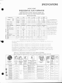
SPECIFICATIONS
I\IOBILE HOME
PRESIDENTIAL GAS FURNACES
CONTAINS SINGLE SPEED HEATING BLOWER OR
3.SPEED HEATING AND AIR CONDITIONING BLOWER
SPECIFICATIONS
\IODEL NO.
SERIES
7660
Nat.
*756i
L.P.
+7
59 I
+7
859
-jt' i5c il
--<:r:-<-
756/856
60,000
48.000
InDut - Btuh
Output - Btuh
7680
7670
E
85 6
59 1859
70,000
s
E
6,000
0.0
6
011
7660
7670
7680
8'16
846
846
3-{9
849
70.000
849
80,000
_i6.000
64,000
il [rlfil
J! -r -,-r I
6-1.ar0i-r
15V/60Cy/lPh
Power Supply
I
ipeed Tap
Horsepower (H.P.)
l
l660-693
7670593
7680{93
L,.;
\{ediu:r
High
lis
115/60/1
d
Volts/Cycle/Phase
F
RPM
800
800
Amps.
5.0
78
29s
510
15
15
600
730
7l_i
!srl
rVatts
itatic
Pressure
& alir Delivery
F.l
F.l
ca
-
C.F.M.
9x7
lG314" x 7"
lcroll
9
10"
-s
60
r0i0
t)0
610
665
20
._:,1
30
6
lG3,4" ..
i:i
'70
r
-:-=
l"
NOTE: Approved for 0 to
4.500 feet elevation, for
elevation above 4,500 feet
dcrate furnace 4 percent
I
vl
5b
80
5
ilheel
C.G.A. REQUIREMENTS
t6
rl6
/10
NOTE: For elevations above
2,000 feet, derate furnace
4 percent for each 1,000 feet
of elevltion above sea level.
I1-<\' 60Cr-/1Ph
758G590
7670-590
7660-590
Blower Assembly
A.G.A. REQUIREMENTS
for each 1.000
ele\
t-eet
ation above
sea
of
level.
0:_i
5
l0'
1l
. l" \ \ Trrn:I.rrmer
The basic difference between the 7600-,00:3:.3s:l:r--:.-e ird tl'.e lt'00-r00 series iuririe
* The 7600-700 Series fitrn:.c
.'.::::::i'rt':
rs
tl'Le
transformer.
The 7600-700 series furnace is equipped
riith r l0 \..\ Ilirnsirrrmer.
ll.l3
See ligures 16. l7
See tigures
and l-1.
*itn: +0 \'.\ tr:rnsirrrmer.
and lE.
This difference in transformers also meilns r slrqlii diiiererlce in tlre rvirir.rg of this tlrnace slien
installing air conditioning. When installing air curnditioning *ith this turnace jt is important that a
determination be made as to the size tr3nsfLrrmer installed in the furnace. Then. consuit the
The 7600300 series furnace is equipped
appropriate wiring diagram shown at the end oi tiris book.
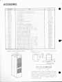
LOOK AT THIS WIDE CHOICE OF AVAILABLE OPTIONS
Note: Oil Solar-Pak Vaporizing (Pot Type) Furnaces are available as a regular stock item.
K
CUSTOM
EXPANSION
VALVE
A-COtL
(Tons)
DELUXE
EXPANSION
VALVE
DENTIAL
SYSTEM
PRES
I
:- J Output
::: -i-cs - sied
r,
A.COIL
(To ns)
I
| 6256-830
| 'o,2' z'3'31
G
A
(r
2' :-3-3'
BLOWER
(SH I PPED
WITH
FURNACE)
Single sper
z
Htg Only
z
Single speed
Htg Only
az5a 830
':'
STANDARD
Available
tn
M id-
'97'.
Single speed
Htg Only
BLOWER CONVERSION
FOR A/C
AND
7660_6921
| 7i50.5-a01
for
2.21/z
ton
or 2-21/z lon
or 3 ton
or 31/2 ton
for
f
(Tons)
WITH
FURNACE)
7660-6921 Iot 2-21i2 ton
7660-6931 for 3 ton
7660-6901 for 31,, ton
7660_6901
(SH I PPED
FILTER)
7660-6931 for 3 ton
7660-690'f lor 31iz ton
7660.692 1
7660,6931
7660-6901
THERM.
OSTAT
CONDENSERS
(PACKAGE INCLUDES
THERMOSTAT SUB BASE
31,/z
ton
or 3' 2 ton
Pres identia I 2-21/z -3-31/z
Polar Prince 2-21/z-3
Pres
idential
2-2t 12-3-31/z
15'
15/
Polar Prince 2-21/z-3
Presidential
2-21/z-3-31/z
2-21 12-3-31
15'
251
z-3-3
z-3
Heati ng
Only
25'
1
5'
25'
32=
':
H
eati ng
On ry
40,
2
eati ng
Only
Polar Prince 2-21 2-3
Presidential 2-2'
Polar Prnce 2.2'
H
401
Polar Prince 2-21/z-3
Presidential
25'
40'
.:
Optronal
Opt ion
a
ACCESSORIES
Pari
N
l
7660-28
7660-281
6256-8.r0
6256-8-.r
6256-625
6256-6,10
6256-7 I 5
625 6-7 I 5
625 6---10
6156-E I 5
615 6-E
I
l
6156-\-1()
6156-r6( I
-66(r-5-l-l
- 66( r-j
-19
-f,6t)-r.
I
l
- 66()-6.1-1
- 66()-r.li
660-6f.9
- 66()-6 - 9
-660-6 I 9
.66()-6
l9
;660 \ 69(
7
7
660-69
660-69
l
-l
7660--05
7
7
7
660-701
660-706
660-708
1660-622
660-671
7660-62 I
7 660-623
1
1
610-6t9
1
610-629
1
610-670
670-630
7660-625
1 660-621
7660-626
7660-628
7
I 660-61
C'
C
I
6256-8 I 2
6256-6 I 5
A
7660-620
7670-.170
t
Itenr
umber
6
6
6
-t
(.-
J
I
-ilinr
RLng
{
l'kg
l
)
-{.00 Scrie\
-6(l(l
-60(l Sr-rir':
-60() 5r'lt.':
I ---1 ttrn unit'
I ---l ton unit.
li..--l t()n unit\
-'1,. ton unit5
I'r:uh.rrr:cd Lirte
P::,lr.u-:eJ Iirrc
['r.'chrLtgcd l-inc
Pt:lltrrt-r.:cJ Line
I'rechlrged I inc
Pre.hrrrged I inc
-1( ' l'r.clrrtrS:d I ine..
R :ar lntakc Prechargcd-fubing Kit
I
3f'1
-j/,r-i
Clrille
-onr Suppl) t-ine (l-i" e\tended. l'kg l)
ont Suppll Line (l87r" ertended, Pkg l)
'ont Suppl) l-ine (13" extended. Pkg 6)
l. ont Suppl) I inc (l{ifr," cxtendcd. Pkg 6)
t: " t)cep DrLct Conncctor ( Pkg l). 8[" to l ] r. ' D:'::
lt " Dee p Duct Connector' (Pkg 6), EZ" to I I ." L).'::
t( " Dccp Duct Conncctor (l'>kg l). U/r" to llL." L).'::
l( " Dce p Duct Cortncctctt (Pkg 6), l'l/r" tc, ll ." D:::
I Specd Air Conuitioning Elloucr l'kg..
F
F
F
Spccd Air (-onditioning BIorlcr ['kg
Spccd Air Conditioning Bloucr [)kg
R ool' .lack \\'edgc (2 x l2 pitch. pkg l)
R :roi.Juck Wcdge (2r l2 pitch. pkg 6)
2
3
R
R
rol Jack \\'edgc
(4
x I 2 pitch. pkc
|
7600
7600
7600
7600
7600
7600
7600
7600
7600
7600
7600
7600
7600
7600
7600
7600
7600
7600
7600
7600
7600
7600
7600
..
) ,..
rot .luck \\'cdge (4x l2 pitch. pkg 6)
St andald l)uct Cotrncctor (l4" Pkg l), %" to
I .' I).
I ." t).'
I ." f).'
I ." D:
to j" l)r'r:
i\'l cdiLrm [)uct Conrrector (16" t'kg 6). -]%" to i" [).r::
j" [)tr:
N1 cdiurr [)uct C'onr]ector (14" Pkg l), -l/i" to
l\l cdiunr l)uct Connector (14" Pkg 6). li(" to 5" Drr:
E: ltcndcd l)uct Ctttrncctor (l6" Pkg l).'1r7l" to I .' t)
[:; rtcnded [)Lrct C'onnectoT (i6" Pkg.6)..1fi" to I .'Il
F-; llcndcd [)uc1 Cottnectot' (l:1" Pkg l). 4rl" to 1 ." t)
- . t)
E: ltcndcd l)Lrct ('onncctor ( 1.1" Pkg 6). 4/r" to
luptcr'l)ucka-ue (l'kg l)for 14" DtLct Slstent
to
to
ttt
Iuptcr l)uckrLge ( I)kg I ) l'or 16" Duct S) stenr
,,rlirr
I
ton ,n,,t
7(100 Series
...
St andard Duct C'onnector ( 14" I'kg 6). rA"
St andirrd [)uct (]onncctor ( 16" Pkg l). X"
St rrndard Duct Conncctor ( 16" I']kg 6). Yt"
M cdiunr Duct Connectot (16" Pkg l). -j/5"
ton units
7600 Series
7660. 7670, 7680
7600 Series
7600 Series
7600 Series
7600 Scries
7600 Scries
7600 Series
7600 Series
F Itul \\.clllhl\
\ir
Serie's
-6()0 Scric.
-6()0 Srt lJ:
Pr..lt:'rrr.l line
R -'tLrrn
Scr ics
-600 Sc'rics
:rlrng R,n-l {l'kg. )5) ... ......
,l (,l,r J ri.,,, i'r-{tnui i ng c., j i i ili;;;;ii;', \',ii' .,
: C,rndititrning Cooling Coil (Expansiort \.tlr:t
rr C-ontiitirrning. Coolitrg Coil (Erprnsion \.rlrc'
I'l:eh.tr!:cd I itrc
'
i
,
scd On
-(.00
herttrtr.t;rt Sub-hrsc
6 ART] INST]I,ATED.
Scries
Serics
Serics
Serics
Serics
Scries
Series
Serics
Series
Scries
Series
Serics
Scrics
Scries
Series
Series
Series
Ser ies
Series
Serics
Serics
Serics
Serics
*6 PRECHAR(;ED I,IN[, NI.JI\'IBERS ENDINC; IN
INSTA I,I,ATION SPTI(]I FI C'ATIONS
Both state and t)u.: ;,',.ys..httuld bc consulted bet'ore
instiilling the lLrrn.:;:
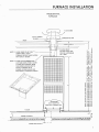
F!A\iCE
a!€lii\CES
-:;
2'65
S€ lTB
3a+ : r:E
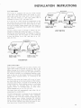
Fr..: i 1:B clo*t)
Closet door grille must have a
minimum ol 200 so in free area
t1 pical d istributitrn \_\ stcnr is short n above. l-he main
duct should be nr'r:rnallcr than 4 x l6 with any branch
ducts at lcrrt -l r \ Registers should hal'e a l'rcc arca
A
(except 1'or batlrrtrorn) ot'2E square inches minirnLlm frce
area. ln no casc shoLrld lcss than six floor register\
bc used. Better results arc generall)' obtained s ith
se\
cn or ei-eht rcgisters.
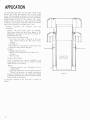
APPLICATION
The perlormance of a heating or cooling system depends
lirst of all on the quality of the equipment; secondly,
on the design of the distribution and return air slstem;
and last but not least. the workmanship
Lrsed
in installing
thc s1'51sm.
The best of equipment, r.r'hen improperly installed, will
not deliver satisfactory performance to the customer.
When the application ol' heating equipment or cooling
equipment is to be made, the procedure to use
selection and application is as follows:
L Calculate the heating or cooling load.
2. Sclect equipment.
3. Double check equipment blower capacities.
in
the
CALCULATINC THE SYSTEM LOAD
bc
To insure correct systcm sizing, a survev should
-fhe heat
made of the structure to be air conditioned'
loss and heat gain should be calculated in accordunce
with the procedure contained in the Natitlnal Warm Air
Heating and Air Conditioning Association Manual J.
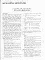
COMPLY WITH LOCAI, CODES
The installer should familiarize himself with and comply with all local codes and regulations which govern
the installation ol this t1,pe eqLripment. Local codes and
regulations take precedent over any recommendatior.rs
contained in these instructions.
ln lieu of Local Codes, the ecluipment should be installed
in accordance with the National Electrical Code, and
in accordance with the rccommendations made b1' the
National Board of Fire Underwriters.
CHECK ELECTRICAL POWER SUPPLY
The electrical power supply should be checked to'determine if adequate power is available, and near constant
voltage can be maintained. lf there is any question concerning the power supply, contact the local power company for corrections; otherwise, unsatisfactory performance may result.
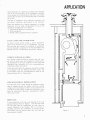
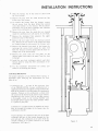
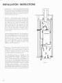
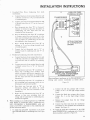
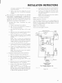
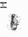
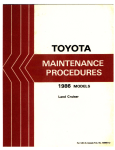
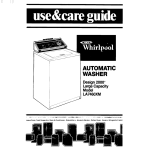
ROOF JACK
close inspection ol the cut-a-way drawing of the roof
jack and furnace shown in Figure 1, will show that both
the flue pipe and the combustion air tube must be
securely attached to the furnace. This is to insure a
complete circuit for the combustion air and flue gases.
The .f urnac'e will nol operate unless the roo/ jat'k has
A
been
properlf installed.
Figure
1
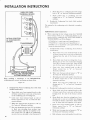
APPLICATION
The telescoping flue pipe must be firmly seated on the
furnace flue collar and secured with a sheet metal
screw. The telescoping combustion air tube should be
pulled down and sealed against the top of the air chamber
located inside the
top of the furnace. The
straps,
attached to the combustion air tube. should be secured
to the top of the furnace with sheet metal screws. Sheet
metal screws should not be longer than % inch.
Problems assoc'ialecl u'ith intproper roo./ jack
installation.
Problem: The main burner comes on normally.
Main burner flame and pilot flame begins to lift
immediately, and floats to the top of the heat exchanger then goes out.
Cause: This is an indication that:
L The inner flue tube is missing or has not
been securely sealed to the flue outlet of the
furnace,
2. blocked flue.
This results in a recirculation of flue gases and
extinction of main burner and pilot.
Solution:
l. Replace inner flue tube,
flue tube to the flue outlet of the
2. Secure the
3.
furnace,
Remove block.
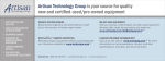
CUTA.WAY OF THE
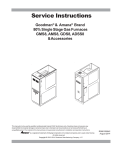
Problem: Pilot outage.
Cause: Combustion air tube not installed or not
sealed against the top of the air chamber located
inside the top of the furnace.
7660-7101 ROOF JACK
Reason:
pressure zone. Downdraft will extinguish pilot.
2. Drawing combustion air from inside the home.
Defeats the purpose of sealed combustion.
l. Different
Solution: Combustion air tube should be installed
and sealed against the top of the air chamber located
inside the top of the furnace.
A
cut-a-way drawing
Figure 2.
of the roof jack is shown in
Figure
2
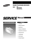
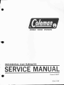
FURNACE INSTATTATION
PRESIDENTIAL
FURNACE
FLUE GASES
-l
--
--1-
CAULK UNDER
COMBUSTION AIR
!i
illr-rl
ROOF
- ROOF CAVITY
ilt, -TF
r-r,-
iri'tl
NOTE 1. SLIDE INNER FLUE
EXTt :ND THI IU THE
lt
ll
1l
TUBE-
DOWN FIRMLY OVER
hai
FURNACE OUTLET AND FASTEN
WITH ONE (lISCREW.
t;'
i^E
sf i
JGE MUI ST
-FLAI
CEIL INGAM INIMUM
oFl INCH
>('^N
Ln
;i5;bi
>F>=
!-!3
S<J1u
-u-o
8P8E
NOTE 2. SLIDE OUTER COMBUSTION /
AIR TUBE DOWN FIRMLY OVER
FLANGE ON FURNACE. BEND
TABS DOWN AND SECURE TO
TOP OF FURNACE WITH
SCREWS. (SCREW HOLES ARE
PROVIDEO IN FURNACE CASING).
5:5
t]r
r
tcc
cotrX
8e8i
JIJ
Lurr{
u.r>uri
eseE
o<ol
(: {h
: ol
FFT\F
6)Fo)^
N
oooE
FFF.
, til;-b
Y OOO)F
7
9
>>>>
; oooo
trEl!CE
4 rl.EErL
6
IJJ UJ tIJ IIJ
O
e JJJJ
g adddd
<<<<
+ FFFF
-
j- (nUrurO
u llll
o;aaa
<<<<
F
;.hQo@
g:lsl
I
/
?
-l
)
WARM AIR DUCT
;l
FRESH AIR
y't--)
CHUTE/
f
..
n
vX
E
FFFF
NtsN@
oooo
(o(o@@
(o(o(g(o
tsFl\N
FURNACE INSTALLATION
PRESIDENTIAL
FURNACE
COMBUSTION AIR
CAULK UNDER
FLANGE--ROOF
WEDGE
2ti2 i I
CAULK UNDER
ROOF WEDGE
:^
st:
ROOF CAVITY
i@
lr.,
lo
DPr N
ll3
E-L
-\L
E
a
?s?
ouo lt
o
lJ-^lI
o
oXo
o;o
9
E=cE
FLANGE MUST
EXTEND THRU
NOTE 1. SLIDE INNER FLUE TUBE
DOWN FIRMLY OVER
OUTLET AND FASTEN WITH
oNE (1)SCREW.
CEILING A
MINIMUM OF
I
,JT t
E^E o
o
oXo
J
o:o
l!
Jl!J
1 INCH.
NOTE
2. SLIDE OUTER
rtlr
AIR TUBE OOWN FIRMLY OVER
u\lll
FLANGE ON FURNACE. BEND
2 TABS DOWN AND SECURE TO TOP
OF FURNACE WITH SCREWS
(SCREW HOLES ARE PROVIDED IN
FURNACE CASING).
egB
uJ
o
o
33? AIN
:tsFN
b:
O)FO)
o
ooo
F
FFF
o
,Y LL'ooo o
9
- >>>
ooo =o
I GEtr E
O 1l-lr.1l- tt
O IJJ IJJ IJJ ul
i* JJJ
rr
+
F
u
moo
<<<
FFF
(hoo
f f l
o
F
o
f
I
o aaa o
F <<<
E eee, I
c:ls
r)hi
N
;
@
u
n
09
ooo (o
X (o(o(o o
EXTENDED OUCT
ADAPTER AND DUCT
CONNECTOR
RRR
I
WARM AIR DUCT
EXTENDED FRESH AIR CHUTE
F
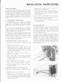
INSTALLATION INSTRUCTIONS
GAS PIPING
Route the gas piping or tubing to the furnace. Use th"
black iron pipe or %" O.D. copper tubing If the piping
length exceeds 40', use 't7^" black iron pipe or '/a" copper
tubing.
When using natural gas, branch tubing may be copper
internally tinned or copper tubing containing not more
than 75 percent copper. When using L.P. gas, tubing
may be type K. Be sure to check local authorities for
any other requirements concerning gas piping. It is
recommended that a main shut-off valve be located in
the gas supply line external to the furnace. This shutoff valve is required by AGA as well as some local
codes.
When making the connection at the gas control valve,
use a wrench on the inlet side to prevent twisting the
valve body which could result in service problems.
After connections have been made, be sure all joints
are checked with soap suds to detect any leaks. This
should also include a check of the furnace controls
and piping. NEVER CHECK FOR LEAKS WITH
A LIGHTED MATCH.
CAUTION: DO NOT TEST THE FUEL SYSTEM AT
MORE THAN 14 INCHES WATER COLUMN AFTER
FURNACE HAS BEEN CONNECTED TO FUEL LINE.
ANY TEST CONDUCTED ABOVE 14 INCHES WATER
COLUMN MAY DAMAGE THE FURNACE CONTROL
2. Make sure all piping and tubing is free of foreign
matter. Apply thread seal to male threads only.
t7r" pilot tubing bween valve and pilot
burner assembly. Pilot burner assembly m ust be
mounted rigidly in a position where pilot will ignite
main burner when it has been reduced to smallest
flame which will hold thermomagnet safety' valve open.
4. t/,s" external vent connection is located at outlet end
of valve. Connect one end of vent tube to fitting on
valve and position other end near, . but not in, pilot
flame. Main burner flame must not impinge on gen3. Connect
erator cartridge or vent tube.
5. Make sure all wiring connections are clean and tight.
Screw thermocouple bushing in fingertight, plus I
turn. with small wrench. DO NOT OVERTIGHTEN.
6. Refer to information furnished with furnace for
proper heat anticipator sctting.
LIGHTING/ RESET
DIAL
VALVE AND VOID THE WARRANTY.
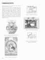
DESCRIPTION
The B57 Midgitrol (Coleman Part No. 7660-3261) is a
combination gas valve which provides all manual and
automatic control functions required for operation of
gas fired heating equipment. This valve is suitable for
use with all gases.
The B5l includes (l) permanently lubricated shear
seal, disc type gas cock, (2) thermomagnet safety
valve, (3) main line automatic valve, (4) pilot gas adjustment valve, and (5) pilot line filter and pressure regulator (optional).
EXTERNAL
VENT
CONN
MANI FOLD
PRESS. TAP
PI
LOT
GAS
CONN.
Figure 3.
LIGHTING PROCEDURE
l. Turn thermostat to lowest
selting.
Turn to PILOT. Press dial in and
light pilot. Hold for 60 seconds and
OPERATION
release.
The l00\a shut-off pilot safety section
power
couple
of low
operates from
bY a 2500G tYPe thermo-
2. Turn dial counterclockwise to ON.
d bY Pilot flame. In
Use this position for thermostat
control. Set thermostat for desired
event
outage, safetY valve shuts
off all gas.
Main line automatic gas valve opens and closes in response to thermostat or other controls wired in 24 volt
circuit. 24 voitt power is provided by an external
room temperature.
3. Shut Down Procedure. Press dial
in and turn clockwise to OFF. Use
this position when complete shut-
transformer.
INSTALLATION
Use valve within following operating ranges:
Maximum operating pressure: t/z psi (14" WC)
Minimum operating pressure: I oz. (2" WC)
Maximum ambient temperature: 175"F.
l. Valves with Part No. 7660-326 I are step open type
and must be mounted upright in horiz.ontal line.
down is necessary. (Use PILOT
position lor temporary or seasonal
shutdown.)
ADJUSTMENTS See Fig.3 for LocationPilot Cas Adjustment. Remove pilot adjustment cap
screw and turn pilot adjustment screw to produce nonblowing blue flame covering top t7o" of thermocouple
tip. Replace cap
screw.
INSTALLATION INSTRUCTIONS
OLO STYLE
REG CAP
VALVE
BODY
REGU LATOR
AND SCREEN DIAPHRAGM
AND/OR GASKET
DIAPHRAGM
ASSEMBLY
ASSEMBLY
GASKET
ASSEMBLY
THERMOMAGNET
VALVE
Figure 4. Typical Cross-sectional
MILLIVOLTMETER TEST
Use 0-50 millivolt scale. Place meter test probes as
shown below. lf meter needle moves to lett of zero or
no reading is ind icated, reverse probes. Take all
readings with pilot burning and thermostat contacts
closed. (Main burner "ON.")
If
reading is less than 7 millivolts
l. Adjust pilot gas.
2. Clean primary air holes.
3. Clean pilot burner orifice.
4. Replace thermocouple.
Figure 5. Cutaway View of
Cap Installed for Natural
Gai. Note Relaxed Spring.
Figure 6. Cutaway View of
Cap Installed for L.P. Gas
Usage. Note Compressed
SPring.
trNOTE: Old style convertible regulator cap is identified by a double
hex. New cap has only one hex tor easier identification of
gas conversion position,
REGULATOR ADJUSTMENT
The regulator has been factory adjusted to
values
stamped on valve.
For LP gas the regulator is not adjustable.
equipped with a
For natural gas use, the valve is
-fo adjust regulator,
limited adjustment type regulator.
install a measuring device in tA" NPT pressure tap
near valve outlet. Remove convertible regulator cap
and spring.
REGULATOR CONVERSION
WARNING
When t'onverting ttalve f rom or to LP gas use, it vrill
be necessar-t' lo ('honge ntain hurner orifit'e. See /urnat'e nanteplate f or t'ontplete instu('lions.
CONVERTIBLE
REG. CAP
E
t=
E
HOW TO CONVERT
REGULATOR
SPRING
REG. ADJ.
SCREW
convert valve pressure regulator from liquefied
petroleum gas to natural gas, or the reverse, lnvert
the convertible regulator cap on the valve. See Fig. 3.
For Natural Gas:
Install convertible regulator cap so that hex portlon
and "NAT GAS" marking appears on upper end of cap.
To
VALVE BODY
Figure 7. Adjusting Regulator for Nat. Gas
(See Figure 5)
CAUTION
For Liquefied Petroleum Gas:
Install convertible regulator cap so that hex portion is
at lower end and "LP GAS" marking appears on upper
end of cap. (See Figure 6)
Do not strett'h spring v'hen rentoving ./rom regulator
stenl.
lnsert screwdriver into the two slots of regulator
adjustment screw (See Figure 7). Turn adjustment screw
clockwise
to
increase pressure, counterclockwise to
decrease pressure. Replace regulator spring.
CAUTION
When inverting the converlible regulalor t'ap ntake sure
that spring below' t'ap is nol rttisplacerl
l0
NOTE: Make sure regulator spring is firmly attached
to regulator stem. Use a Phillips head screwdriver or
similar blunt ended object to press spring down until
you hear or feel it snap in place. Replace convertible
regulator cap with "NAT CAS" marking in up position.
INSTALLATION INSTRUCTIONS
PILOT ADJUSTMENT
The pitot flame should be adjusted to bathe the end of
the pilot thermocouple with approximately t/r" of f)ame.
The pilot flame should appear blue on natural gas, and
blue with yellow tips if operating on L.P. gas. Remove
the pilot adjusting screw cover cap from the control
valve and adjust the underlying screw to obtain the
proper pilot flame. Replace the cover cap in the control
valve.
GAS CONVERSION INSTRUCTIONS
The PRESIDENTIAL series furnaces are equipped
to burn either natural gas or [-P gas. By using the
proper orifice and adjusting the pressure regulator
and pilot, the furnace can be converted to burn either
gas.
For LP gas, an LP gas identification tag should be
wired to the burner manifold, the orilice in the burner
should be marked "t-P," and the pressure converter
should be adjusted to the "LP" position.
For natural gas, a Natural gas identification tag should
be wired to the burner manifold, the orifice in the
burner should be marked "NAT," and the pressure
converter should be adjusted to the "NAT" position.
The extra orifice and gas identification tag are in the
cloth bag attached to the pilot line.
CONVERSION FROM NATURAL TO LP GAS
l. Be sure gas and electricity to appliance is shut
off.
4. Reverse valve regulator pressure converter to
read Nat. Gas. See See Fig. 5
5. Push orilice holder back in place and replace the
valve u'ith the two screws previously removed.
Connect pilot feed tube to valve. Be sure all connections are tight.
6. Wire Natural gas idcntification tag to pilot line.
7. Store replaced orifice and LP gas identil'ication
tag in cloth bag and attach to pilot line.
8. Use pilot adjusting screw to adjust pilot flame.
Sce pilot adjustment.
THE 7660-528 BURNER
The 1660-528 burner is a mono-port type burner with
a stainless steel flame spreader mounted above the
burner port to spread the flame out nearer the walls
of the heat exchanger. Just inside the burner port is
a flame retainer that holds a portion of the gas flame
down around the burner port.
The flame should be slightly yellow while the furnace
is operating. The burner flame should not rumble or
roar like a blow torch (furnace receiving too much
combustion air). The air shutter adjustment may be
pushed in to provide more primary air and pulled out
to reduce the amount of primarl' air being delivered
to the burner flamc. This adjustment depends upon the
average winter temperature and thc geographical location of the furnace.
2. Disconnect pilot fecd tube from valve.
3. Remove the two screws holding valve to valve
bracket and pull valve with orifice holder back and
out of burner support exposing the orifice. Change
to burner orifice marked LP. found in the cloth
bag attached to the pilot line.
4. Reverse valve regulator pressure converter to
read LP Gas. See Fig. 6.
5. Push orifice holder back in place and replace
thc valve with the t\\'o screws previously removed.
Connect pilot feed tube to valve. Be sure all connections are tight.
6. Wire LP identification tag to pilot line.
7. Store replaced orifice and Natural gas identification tag in cloth bag and attach to pilot line.
8. Use pilot adjusting screw to adjust pilot flame.
See pilot adjustment.
CONVERSION FROM LP TO NATURAL GAS
l. Be sure gas and
olf
2.
J.
electricity
to
appliance
is
shut
.
a
Disconnect pilot feed tube lrom valve.
Remove the
two
screws holding valve
to
valve
bracket and pull valve with orilice holder back and
out of burner support exposing the orifice. Change
to burner orilice marked Nat. found in the cloth bag
attached to the pilot line.
ll
INSTALLATION INSTRUCTIONS
7660-575 HEAT EXCHANGER
7660-575 heat exchanger is constructed with
stainless steel balfles installed around its lowcr,
interior portion. This is to give greater protection
against burnout from continuous contact with the burner
flame. Located in the top area ol the heat exchanger is
a stainless steel baffle deflector to keep the direct
upflow of heat from coming into immcdiate contact
with the top of the heat exchanger. lt also slows the
rising heat down before it escapes up the l-lue.
The
REPLACING THE 7660.575 HEAT EXCHANGER
l. Turn off the electrical supply to the furnace.
2. Turn oll the gas supply to the f'urnace.
3. Disconnect the rooljack from the furnace.
a. Remove the screws from the roof jack hold-down
straps and slidc the combustion air pipe up out of
the way.
from the vent-pipe and slide
it up out ol the way.
4. Disconnect the fuel line at the union, next to the
gas control valve, and from the gas supply line
below the floor. Remove this section of pipe so that
b. Remove the scrcw
the furnace can be removed later.
5. Detach electrical supply and thermostat wires from
the furnace.
6. Remove the lurnace blower at this time by (a) disconnecting the electrical leads from the blower,
(b) removing the screws from the lower side of the
angle that holds the blor.r'er to the furnace, (c) sliding
thc blower lorward out of the I'urnace and setting
it out of the way.
7. Remove the two panels from the coil cavity of the
furnace.
8. Remove the duct chute and duct connector from the
bottom of the furnace. Take the four screws out of
the top of the duct chute and lilt out.
9. Detach the lurnace straps, located at top, back
corners of furnace. l'rom the wall.
10. Remove the two nails or screws used to anchor
the furnace to the floor. Each anchor is located just
a lew inches back from the front corners of the base
of the furnace.
t2
INSTALLATION INSTRUCTIONS
ll.
l2
13.
14.
l5
l6
11.
t8
Slide the furnace out of the closet or alcove and
lay it on its btrck.
Rernove the nuts I'rom the studs around the flue
at the top of the furnace.
To remove the burner from the furnace, remove
the six screws from the plate behind the control
'filt the burner
valve that lastens it to the furnace.
and withdraw
heat
exchanger
of
the
down
out
end
burner from combustion air tube.
Remove the nuts lrom the studs that are located
inside the combustion air tube and at its very back.
Remove the mid-panel that separates the upper
and lower areas of the furnace.
Remove the cover plate from the electrical control
box. Remove the two screws in the control box that
are located along the side nearest the furnace wall.
Remove the internal front panel of the lurnace by
removing the screws from around its sides. Lift
both the furnace's internal panel and the heat exchanger out of the furnace body.
Remove the screw from the view plate on the
internal panel and detach the panel from the heat
exchanger.
the new heat exchanger, gaskets and other
lurnace parts by using the above procedures in re-
19. lnstall
verse order.
20. Use the installation instructions
lor correct pro-
cedure in re-installing the furnace.
AIR REQUIREMENTS
The proper operation of any Mobile Home furnace is
dependent upon satisfying the requirements for four
types of air.
l.
As seen in the cut-a-way vlew
Comhustion air
of the PRESIDENTIAL furnace, combustion air is
supplied to the burner through the roof jack. Down the
back of the furnace to an area below the combustion
chamber. Primary air for combustion is drawn into'
the venturi of the burner by the action of gas velocity
(aspiration) in the venturi. This air and gas mixture
is thoroughly mixed in the mixing chamber and
discharged upward against the flame spreader where
it is ignited by the pilot.
Combustion is completed with the addition of secon-
dary air around the outside
of the burner into
the
combustion chamber.
The hot products of combustion then rise in the heat
exchanger and pass to the outside through the flue
and roof jack. All combustion air is taken from the
outside resulting in a system referred to as sealed
combustion. See Figure 8 .
Figure 8.
l3
INSTALLATION INSTRUCTIONS
Warm air is distributed through
2. Cirt'ulating air
the duct system -by the circulating blower located at
the top of the furnace. The operation of the blower
is controlled by the fan switch which senses the heat
inside the furnace. This is an automatic switch, located inside the control panel.
3.
Fresh air
coaches, due to location, may
- Somemoisture
problem. ln some cases
have an excessive
the moisture problem may be so bad that condensation may cause water spotted walls or ruined paint
jobs. When the air is warrn, the moisture in the
coach is invisible. Since warm air can hold more
moisture than cold air, air containing too much
water vapor condenses to form frost or water whenever it comes in contact with a cold surface. One of
the most common illustrations of visible condensation in the coach is the formation of water or frost
on the windows.
Cooking, washing, bathing, etc., all add moisture to
the air, and large amounts show up as condensation.
The small rectangular chute on the bottom of the
furnace brings in fresh air to the circulating blower.
The fresh air which is brought into the circulating
blower is then distributed as warm air through the
duct system. This cool outside air, after
being
warmed, is capable of absorbing moisture, thus
helping to reduce condensation.
air
The louvers on the top front of the
return air. Return air must be proadmit
furnace
vided back to the circulating blower in order to
provide air distribution. Do not enclose the lurnace
or otherwise obstruct these louvers. To 'do so will
cause the furnace to limit and go to pilot.
4 Return
The Presidential furnaces are designed to
give
superior air-handling capabilities. This results in an
air temperature rise of 165'F. compared to the
200'F. rise that the Solar Paks were designed for.
lf you use less than 200 square inches free area
return grille you are reducing the air flow across the
heat exchanger and just asking for service problems
resulting in high temperature cycling on heating.
To avoid operational problems on the 7660 furnace,
the 7660-5491 return air grille must be used. This
grille has 200 square inches of free area and the use
of less free area can result in operational problems.
t4
I
I
tl.
Figure 9.
INSTALLATION INSTRUCTIONS
FAN SWITCHES
'I'he furnace is equipped with one fan switch located
at the top of the control panel. This switch is a normally open switch that closes with a rise in temperature. The fan switch is a disc type switch that is
calibrated to close at 105', and open at 90o.
As in the case ol a limit switch, the temperature on the
fan switch does not necessarily mean that the air will
be the same temperature. A fan switch, due to its location on the furnace, might actually start the blower at
an outlet air temperature that is above the calibrated
temperature.
to indicate the temwill open or close
The disc switches used are marked
perature at which the switch
ELECTRICAL
MOVEAELE
CONTACT
BI.METAL DISC.. HOT
Br-METAL OrSC. - COOL
CIRCUIT OPEN
crRcutT cLosEo
LIMIT SWITCH
and the type switch being used. For example, a marking
of Fl40-30 means that the switch is a fan switch set
to turn the blower on at l40o and shut of at ll0o
(140-30= I l0).
ELECTRICAL
TERMINALS
MOVEABLE
MOVEABLE
CONTACT
CONTACT
THRUST
EUTTON
BI.METAL DISC.-- COOL
CIRCUIT OPEN
BI.METAL OISC.: HOT
CIRCUIT CLOSED
FAN SWITCH
LIMIT SWITCHES
limit switches. The
left side of the
the
located
on
is
limit
switch
upper
blower housing in the blower compartment. The upper
limit shuts the furnace off in case the upper portion of
the furnace overheats. An overheating condition could
exist at the top of the furnace because of circulating
Each furnace is equipped with two
blower failure. electrical failure,
or overfiring of
the
furnace.
The lower limit shuts the lurnace olf in case of excessive heat build up in the lower portion ol the furnace'
The lower limit switch is located at the bottom of the
control wiring box. Some common causes of overheating
in this region are restricted ducts, too many floor
registers closed, or restricted inlet, i.e. dirty filter,
clothes hanging near or over the inlet area.
The lower limit will automatically reset when the air
temperature has cooled down.
The disk thermoswitch is operated by the heating and
cooling of a bi-metal disk. Under "hot" conditions,
the bi-metal disk will snap inward thrusting the electrical contacts open; thereby breaking the electrical
circuit. Upon cooling, the bi-metal disk will snap back
out and let the contacts close which will then let electrical power pass through without interruption.
l5
THERMOSTATS
Shown below are the two thermostats used with the
PRESIDENTIAL gas furnace.
Figure l0 shows the Camstat TlTH-180N heating only
thermostat. Figure ll shows the Camstat CB35-E-lF
sub-base which contains the cooling thermostat. The
combination heating cooling thermostat is obtained
when the TITH-180N heating thermostat is affixed to
the CB35E-l F sub-base. When connecting the thermostat combination for heatinglcooling operation.
connect the thermostat wires to R, Y, W, and G tln the
C835E-l F sub-base. Figure 12 shows the internal
wiring of the camstat thermostat. The White Rodgers
heating/cooling sub-base is pictured in Figure l3
and Figure 14 shows the internal wiring for the White
Rodgers thermostat.
Figure 12. Camstat lnternal Wiring
E0t
r r<dat
Figure 13. White Rodgers Thermostat
Figure 10. Camstat Heating Only Thermostat
Figure 14. White Rodgers Heat/Cool
Thermostat Internal Wiring
Figure 11. Camstat Cooling Sub-Base
l6
THERMOSTATS
ANTICIPATION
The operation of a low voltage thermostat based solely
on mechanical means, generally results in wide variations in temperature in the conditioned area whether the
application is for heating or cooling. To insure a more
precise control of area temperature, low voltage thermostats contain heating and cooling anticipators.
In addition to improved room temperature control, heat
anticipation contributes to better air circulation. The
burner may cycle on and off several times during one
cycle of the fan. Since heat anticipators are powered
and effective only during the heating cycle, they are
placed in series with the control contacts. When the
contacts are closed, power is supplied to the heat
anticipator resistor.
MANUAL SWITCHING OPERATIONS
Generally, a sub-base used to control both heating and
cooling equipment will contain two switches, one
marked "FAN" and one marked "SYSTEM."
FAN SWITCH
ON
Constant fan. The fan
will run continuously
re-
gardless of the thermostat demand.
AUTO
The fan runs only as required by the system
operatlon.
SYSTEM SWITCH
only, operates in response
HEAT
- Heating system
to the thermostat.
OFF Heating system and cooling system both off.
Cooling system only, operates in response to
COOL
-
the thermostat.
CAL/TION: Care should always be taken in the alignment of the thermostat attaching screws, as they may
also serve as terminal connectors. If threads are
stripped, a poor electrical connection will result.
INSTALLATION AND SERVICE
l. A low voltage thermostat is a precision instrument and should be treated as one. Care must be
used to insure a level installation with thermostats
using mercury bulbs.
2. Mount on a solid wall.
3. Locate the thermostat on an inside wall four to
five feet above the floor in an area free from drafts
and direct sunlight. Do not locate where directly
affected by lamps, fireplaces, appliances, or on walls
containing hot or cold pipes, ducts, chimneys.
4. Be sure anticipator matches or is adjusted to
match current (amp) draw of equipment being
Insufficient heat anticipation in a heating system results
in the bi-metal lagging behind the room temperature
change. This will cause longer "on" and longer "ofl'
periods with
a resultant larger room
temperature
varlatlon.
A common heating valve current draw is 0.4 amps,
and this should be matched on any adjustable anticipator. If the adjustable anticipator is set appreciably
higher, for example rJ.1 amps, it will increase the
room temperature variations by 3oF. or 4oF. and cause
longer running cycles.
For longer "on" periods, set the heat anticipation adjustment pointer at slightly higher amp value. For
shorter "on" periods, set the pointer at slightly lower
amp value. Move only t/q to /z scale division at a time.
(Never set the pointer at more than I % scale divisions
below the amp rating of the valve or relay current
rating.)
The anticipation function in a cooling thermostat is the
reverse of its heating application. The cooling anticipator is powered during the "ofl' cycle. As the room
temperature increases, heat is applied to the bi-metal
for the bi-metal to close
the contacts. Excessive cool anticipator temperature
decreasing the time necessary
results in shorter "offl' periods, consequently, more
frequent cycling of the cooling equipment. Insufficient
anticipation in a cooling thermostat causes long "ofl'
and
cycles resulting
in larger
temperature
variations in the room.
ANTICIPATION PROBLEMS
HEATING
SETTING TOO LOW
l. Excess anticipation "on" cycles too short.
2. Rapid cycling.
3. Small temperature swings from the setting with
a tendency to drop.
SETTING TOO HIGH
cycles too long.
l. Insufficient anticipation
2. lnfrequent cycling.
3. Wide temperature swings from the set point with
a tendencl to lag.
COOI,ING
RESISTOR TOO SMALL
L Voltage too low.
2. Short
"ofl'
time.
3. Short "on" time.
4. Rapid cycling.
5. Temperature maintained closer
with a tendency to rise.
to the set point
controlled.
connections clean and tight'
lf a heating system has an improperly sized anticipator
and excessive heat is generated in the thermostat, the
result is a short "on" cycle. During periods when the
system is running close to its full capacity, more of the
heat sensed by the bi-metal is from the anticipator
than from room air; and the controlled area temperature will progressively decrease.
5. Make
all wiring
R'.S/.STOR TOO IARGE
l. Voltage roo high.
2. "Off'time too long.
3. "On" time too long.
4. Fewer "on" cycles.
5. Wide temperature swings from the set point with
a tendency to lag.
l7
LIGHTING INSTRUCTIONS
CAUTIOI,{: When lighting the furnace it is important
that steps I through 6 ol' the Lighting Instructions be
followed to purge the combustion chamber of any gas
that might be prcsent in the combustion
chamber.
LIGHTING INSTRUCTIONS
l. Turn thermostatto its lowest setting.
2. Remove lurnace door.
3. Open inspection door.
4. Depress and
turn the gas valve control knob
to
"oFF."
5. Close main gas valve.
6. Wait l5 ntinutes.
CALITION: Since the gas valve in this furnace is
a
step opening valve, the following procedure should be
used when lighting the Pilot.
7. Turn
gas
valve "ON".
8. lnsert match in lighter rod'
9. Turn gas valve control knob to pilot.
10. Depress control knob and light pilot.
I
l. Keep dial depressed lor 60 seconds or until pilot
remains lit.
12. Replace inspection door.
13.
Turn dial to "ON."
14. Replace furnace door.
to cycle the burner "OFF" and
"ON" several times to bc certain that the burner
15. Use the thermostat
ignites properly.
l8
to the desired temperature.
This procedure will allow the gas valve to lunction
properly by permitting a minimum flow of gas to the
main burner at the start. The valve then will continue
to open gradually till iull flow is obtained.
16. Set the thermostat
SHUTDOWN INSTRUCTIONS
l. Set wall thermostat to lowest temperature.
2. TEMPORARY SHUI-DOWN: Turn gas valve dial
to pilot position.
3. COMPT-El-E SHUl'DOWN: Depress dial and turn
clockwise to "OFF."
4. Turn system switch to "OFF."
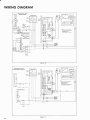
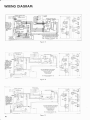
WIRING THE F'URNACE
Connect the I l5 volt 60 cycle leads to the "pigtails"
in the wiring box at the top ol the wiring panel. Secure
with tu,o wire nuts. Connect the low voltage wires to
the thern.rostat.
All electrical wiring within the furnace has been made
at the {'actory. All wirirtg contlected to the unit must
comply, with the National Elcctric Code and any appli-
cable local codes and regulations. A separate circuit
with a lused disconnect should be provided lrom the
main luse hox to thc furnace.
1'he wiring diagrams shown in figures 15, 16, 17, 18
and l9 present a visual picture of the various electrical circuits to be found in the 7600 Gas Presidential
Furnaces.
Figures 20,21,22 and 23 show the low voltage wiring
for the various furnace, condensing units, and thermostat combinations.
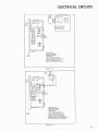
ELECTRICAL CIRCUITS
Atr
BLOWER CONTROL BOX
Wt
ALL MODELS
7600-700 SERIES
7600-800 sERlEs
FU RNACE
CASING
FUR NACES
THIS VIEW SHOWS THE
HIGH VOLTAGE CONNECTION
TO THE FURNACE HIGH
VOLTAGE TERMINAL BLOCK.
Figure
UPPER
L l\4 lT
15
BLOWER
AND
r\40TOR
WIBING BOX
TBANSFORIV]ER
HEATING ONLY
7600-700 SERIES
7600-800 sERlEs
FUR NACES
FURNACE
CASING
THIS VIEW SHOWS THE
LINE CONNECTION TO THE
HIGH VOLTAGE TERMINAL
BLOCK, AND HIGH VOLTAGE
BLOWEB MOTOB CONNECTIONS
FOR HEATING ONLY FURNACE
Figure
16
l9
ETECTRICAT CIRCUITS
BLOWER
AND
HEATING ONLY
7600-800 SERIES
FURNACE SHOWN
SHOWN:
1. INCOMING HIGH
VOLTAGE LEADS,
TBANSFORMEB-40 VA
2
PRIMARY LEADS OF
TRANSFORMER.
3. SECONDARY-LOW
VOLTAGE CONNECTION
FOR HEATING ONLY
APPLICATIONS.
Figure
17
BLOWEF CONTROL BOX
TRANSFORME B
7600 FURNACE
HEATING AND AIB CONDITIONING
(3 Speed Blower is shown)
7600-700 sERlEs. oR
7600-800 sERlEs
FUR NACES
SHOWN:
1
INCOMING HIGH VOLTAGE
LEADS TO THE FURNACE
2. PRIMARY OF THE
3
TRANSFORMER
- CONNECTION
TO THE TERMINAL BLOCK.
HIGH VOLTAGE CONNECTION
FOR MULTI-SPEED A,/C
BLOWER.
Figure l8
20
ELECTRICAL CIRCUITS
BLOWER CONTROL BOX
PRESIDENTIAL
FURNACE WIRING BOX
7600-800 SERIES
FURNACE WITH A
MULTI.SPEED A,/C
BLOWER.
GAS VALVE
w----TocoNDENstNiuNlr
-6LA'c*-
Figure
In Figure
-J
----
19
19 the primary purpose is
to show the inter-
nal low voltage circuit of the furnace. ln the above example,
the black wire goes to the condensing unit, and a yellow
wire runs from the condensing unit to the "Y" terminal
of the thermostat. See Figures 20,21,22 and 23 for
complete low voltage connections.
2l
WIRING DIAGRAM
PRESIDENTIAL WITH
CONTACTOF TRANSFORMER
NOTE:
1
2
urrrs
Eiiroru
oru soue
BorH wtREs WERE BtuE
SYSTEM WIIL NOT WORK
I
7600 700 SERTES FUnNACE
WITH A 20 VA TRANSFOFMER
COND€NSING UNII IS
EOUIPPED WIIH A
TRANSFOFMER AT FACTORY
I
I
Figure 20
PRESIDENTIAL WITH
TBANSFORMER REMOVED
NOTE
1 7600 .
AOO SERIES FURNACE
EOUIPPEO WITH A 40 VA
r.o.- - -{
2
FACTOFV INSIALLED
TRANSFORMEF IN CONOENSING
UNIT HAS BEEN REMOVEO
POLAR PFINCE WITH
TFANSFOFMER REMOVED
Figure 2l
22
WIRING DIAGRAM
PRESIDENTIAL
AND
POLAR PBINCE
CONDENSING UNITS
NOTE
1 7600
7OO SERIES FUBNACE
EOUIPPED WITH A 20 VA
2
3
CONDENSING UNIT FFOM
FACTOFY IS NOT EOUIPPED
WITH TRANSFORMEF
WHEN CONOENSING UNIT IS
USEO WITH A 7600 7OO SERIES
FURNACE A TRANSFOAMER
MUST SE INSTALLEO IN THE
CONDENSING UNII
CON OENSI NG
UNIT
Figure 22
NOTEi
1 75OO AOOSERIES FURNACE
EOUIPPEO WITH A 40 VA
2
IRANSFORMEF 40
Figure 23
VA
CONOENSING UNIT FROM
FACTORY IS NOT EOUIPPED
WIIH A TRANSFORMER
23
INSTALLATION INSTRUCTIONS
7 660A6901, 7 660-6931, 7 660-6921
Air Conditioning Blower Pockoges
APPLICATION
The Coleman 7660A6901 blower, equipped with 4 speed
blower motor; 7660-6931 blower, equipped with 3 speed
blower,motot;and766O4921 blower, equipped with 2 speed
blower motor are for use on all 7600 series Presidential Gas
Furnaces. The 7660A6901 can be set at low, medium, or
high speeds to match from 2 to 3% tons of air conditioning.
The766O493l can be set at low or high speeds to match2
to 3t/z tons of air conditioning. The 766O4921 goes to one
air conditioning speed automatically, to match 2 ot 2% tons
of air conditioning.
The 7600-700 series Presidential Gas Furnaces contain a 20
V.A. transformer. A 20 V.A. transformer is not large enough
to energize the contactor in an air conditioning condensing
unit. Coleman Mobile Home Condensing Units have been
produced both with and without their own transformer. If
you are adding air conditioning to a 7600-700 series furnace,
the condensing unit must contain a transformer. In the event
that there is no transformer in the condensing unit, one must
be ordered (pln 62723a5 l) and installed. The various wiring
hook-ups may be found below under "Wiring."
The 7600400 series Presidential Gas Furnaces have 40 V.A.
transformers factory installed. This series furnace was designed to accommodate addon air conditioners with no
transformer in the condensing units. If adding a condensing
unit to this series furnace, and the condensing unit does have
a transformer, it must be disconnected and removed. For
correct wiring procedures, see the "Wiring" section below.
Two red leads to fan switch.
7660A6901 high -
4
speed
blower
med
7660-6931
high
3 speed
blower
3t4,tons of air conditioning
- 3 tons of air conditioning
low - 2-2/z tons of air conditioning
low
- 3 tons of air conditioning
- 2-2/z tons of air conditioning
The 766O4921 two speed air conditioning blower goes to
the one air conditioning speed automatically, to match
2 to 2r/2 tons of air conditioning.
WIRING
General:
Remove the cover
of the heating thermostat that
is
located on the wall of the home.
Remove the two wires connected to the two terminals
(screws) on the heating thermostat.
Remove the heating thermostat from the wall and keep
for installing the heat-cool thermostat.
Install the thermostat cooling sub-base, packed with the
new blower, on the wall in place of the heat thermostat.
NOTE: Five-wire thermostat cable is required for installing the 'heat-cool' thermostat when using two transformers (7600-700 series).
Four-wire thermostat cable is required for a single transformer installation (7600-800 series).
terminals on the left side of the blower before removing
the blower from the furnace.
24
2
three speed blowers as follows:
6. Remove the auxiliary limit wires from the auxiliary limit
10. Secure the new blower by replacing the five screws used
to secure the old blower.
11. Connect the four wire leads from the blower control box
to the furnace control box.
side.
13. Set up air conditioning speed switch on the four and
leads from the terminal block
and pull the motor leads from the control box.
Slide the air conditioning blower into the furnace.
I
blower.
5. Remove the black motor
9.
Black lead to hot on terminal block or number
12. Connect the auxiliary limit wire from the furnace
control box to the auxiliary limit on the left side of the
fan switch to the terminal block.
thru each side of the blower.
8. Slide the heating blower out of the furnace.
b.
c.
2. Remove upper door of furnace.
3. Remove cover of furnace control box.
4. Remove completely, the orange wire that connects the
Remove the three screws from the front support and one
White lead to common on terminal block or number
side.
INSTALLATION OF BLOWER
l. Shut off'electrical supply to furnace at breaker box.
7.
a.
7600-700 Series (Two Transformerl:
A.
Wlren connecting the low voltage wiring for 1660-100
series furnaces with an air conditioning blower in con-
junction with a condensing unit, WITH A TRANSFORMER, use wiring diagram:
1970A517 for 2 transformers and 4 speed blower or
1970-600 for 2 transformers and 3 speed blower or
1970510 for 2 transformers and 2 speed blower, and
follow the instructions be1ow.
INSTALTATION INSTRUCTIONS
l.
Standard Polar Prince Condensing Unit (with
o
transformer):
a.
Connect black wire from terminal board on side
of blower control box to V2 on terminal board
of condensing unit.
b.
Connect green wire from terminal board on side
HIGH VOLTAGE
TERMINAL BOARD
TRANSFORMER
of blower control box to "G" on the 'heat-cool'
sub-base.
c.
"W' on'heat+ool'
to terminal on gas valve. (In add-on air
conditioning, use wire from valve that was
Run thermostat wire from
sub-base
attached to heat thermostat.)
d.
Run one thermostat wire from "R" on sub-base
to furnace control box and wire-nut it to the
black wire extending from auxiliary limit in furnace. (In add-on air conditioning, use wire thal
ACTUAL POSITION
OF COMPONENTS
SHOWN
was attached to heat thermostat.)
e.
Run a second thermostat wire from "R" on
sub-base to V1 on low voltage terminal board
of condensing unit.
f.
Connect the last thermostat wire to "C" on
terminal board of condensing unit and "Y" on
sub-base.
2.
Presidential Condensing Unit (with transformer):
a.
Connect black wire from terminal board on side
of blower control box to "piggy-back" terminal
on transformer side of contactor in condensinp
unit.
b.
Connect green wire from terminal board on side
of blower control box to "G" on 'heat-cool'
sub-base.
c.
Run thermostat wire from "R" on sub-base to
black wire extending from auxiliary limit
switch in furnace, and wire-nut together in furnace control box. (In addon air conditioning,
use wire from valve that was attached to heat
thermostat.)
d.
e.
Run thermostat wire from "Y" on sub-base to
wire extending from low pressure switch in condensing unit, and wire-nut together.
REMOVE JUMPER WHEN
INSTALLING TRANSFORMER
IN CONDENSING UNIT
When installing a transformer in the POLAR PRINCE con-
densing units connect transformer as shown above.
Figure 24
Run white wire from gas valve to "W' on
thermostat sub-base. (In add-on air conditioning, use wire that was attached to heat
Connect the red wire, primary side of transformer, to No. 4 on the high voltage terminal
thermostat.)
f.
board.
Route the last thermostat wire from "R" on
sub-base to blue wire extending from low
voltage side of transformer in condensing unit,
b.
board.
and wire-nut together.
B.
c.
When installing an air conditioning blower in a 7600-700
series furnace in conjunction with a condensing unit,
NOT CONTAINING A TRANSFORMER, order and
install a 6272.3451 transformer in the condensing unit
per the instructions below.
l.
To install the 6272-3451 transformer in the 6270
series POLAR PRINCE condensing units, See Figure
\9.
Connect the black wire, primary side of transformer, No. 3 on the high voltage terminal
Remove
the jumper from the low
voltage
terminal block.
d.
2.
Connect two blue wires from the transformer
(secondarv) to the terminals that contained the
jumper. See Figure 19.
To install the 6272-3451 transformer in the 6280
series PRESIDENTIAL condensing units, follow the
above procedure, and refer to Figure 20'
25
INSTATTATION INSTRUCTIONS
e.
HIGH VOLTAGE
TERMINAL BOARD
f.
Route blue wire in condensing unit low voltage
box to "R" on 'heat<ool'thermostat sub-base.
Route yellow wire
"Y'
in
voltage box to
on 'heat-cool' thermostat
Presidential Condensing
transformer):
Unit (with field installed
condensing
unit
low
sub-base.
4.
The wiring for this condensing unit is identical to number
above.
7600-800 Series (One Transformer):
Y
o
o
ACTUAL POSITION
OF COMPONENTS
SHOWN
TRANSFORMER
A.
When connecting the low voltage wiring from 7660-800
series furnaces with an air conditioning blower in conjunction with a condensing unit, NOT CONTAINING A
TRANSFORMER, use Wiring Diagram:
1910A596 for I transformer and 4 speed blower or
1970A598 for I transformer and 3 speed blower or
1910A6l I for I transformer and 2 speed blower and
follow the directions below.
1.
Standard Polar Prince Condensing Unit (without
transformer):
a.
Route black wire from terminal board on side
of blower control box to wire nut on black wire
hanging from the side
box.
of the furnace control
b.
Route black wire from low voltage box of condensing unit to wire nut on black wire hanging
from side of furnace control box. There should
now be three wires tied together at this point.
c.
Green wire lrom terminal board on side of
blower control box
to "G" on
'heat-cool'
thermostat sub-base.
I
REMOVE JUMPER WHEN
NSTAL LI NG TRANSFO RMER
d.
IN CONDENSING UNIT
e.
When installing
a
transformer
in the PRESIDENTIAL
condensing units connect transformer as shown above.
f.
Figure 25
White wire from gas valve in furnace to "W" on
the'heat-cool' thermostat sub-base.
Red and green wires tied together from bottom
furnace control box to "R" on 'heat-cool'
thermostat sub-base.
of
Yellow wire from low voltage box of condensing unit to "Y" on 'heat-cool' thermostat
sub-base.
3.
Standard Polar Prince Condensing Unit (with field
installed transformer) :
a.
b.
Route black wire from terminal board on side
of blower control box to wire nut on black wire
in the condensing unit.low voltage box.
Green wire from terminal board on side of
blower control box to "G" on 'heat-cool'ther-
2.
Presidential Condensing Unit (without transformer):
a.
b.
mostat sub-base.
White wire from gas valve in furnace to "W" on
the'heat+ool' thermostat sub-base.
d.
26
Run one thermostat wire from "R" on sub-base
to black wire extending from auxiliary limit
switch in furnace and wire nut together in furnace control box. (In add-on air conditioning,
use wire that was attached to heat thermostat.)
c.
Route black wire from terminal board on side
of blower control box to wire nut on black wire
hanging from the side of the furnace control
box.
Route black wire from low voltage box of condensing unit to wire nut on black wire hanging
from side of furnace control box. There should
now be three wires tied together at this point.
Green wire from terminal board on side of
blower control box
to "G" on 'heat-cool'
thermostat sub-base.
d.
White wire from gas valve in furnace to "W" on
the'heat-cool' thermostat sub-base.
e.
Red and green wires tied together from bottonr
INSTALTATION INSTRUCTIONS
of
furnace control box
thermostat sub-base.
f.
to "R" on 'heat-cool'
Yellow wire lrom low voltage box of condensing unit to "Y" on 'heat-cool' thermostat
f.
Connect the black wire from terminal board on
side of blower control box to above noted wire.
C.
Connect a low voltage wire from side of contactor pull-in coil opposite low pressure switch
to above noted wire.
sub-base.
NOTE: There will now be three wires together
in the wire nut noted above.
When installing an air conditioning blower in a 7600-800
series furnace, in conjunction with a condensing unit
CONTAINING A TRANSFORMER, it willbe necessary
to disconnect and remove the transformer from tlte condensing unit, and wire as follows, by referring to the
appropriate one transformer wiring diagram:
1.
Standard Polar Prince Condensing Unit (with
transformer):
a.
b.
c.
Remove transformer from condenser.
Run red wire from transformer in furnace to
"R" on thermostat
sub-base
Run white wire from
gas
Replace cover of furnace control box.
Replace upper door of furnace.
Lock the heating thermostat on the cooling sub-base, by
placing the hooks on the heating thermostat beside the
screws on cooling sub-base and twisting slightly in a clockwise motion. Tighten screws.
Replace cover of thermostat.
Turn on electrical supply to lurnace.
valve to "W" on sub-
base.
FURNACE CONTROL BOX
d.
Run green wire from terminal board on side of
blower control box to "G" on sub-base.
e.
Run low voltage wire from V2 on low voltage
terminal board ol condensing unit to "Y" on
GAEEN
BLOWEB
MOTOR
--c
sub-base.
NOTE: There is a black wire extending from
the lower limit switch through the side of the
furnace wiring box, with a wire nut attache d to
it. The next two steps pertain to this wire.
2.
f.
Connect the black wire from terminal board on
side of blower control box to above noted wire.
E.
Connect a low voltage wire from "C" on condenser low voltage terminal board to above
noted wire.
NOTE: There will now be three wires together
in the wire nut noted above.
Presidential Condensing Unit (with transformer):
a.
b.
c.
Remove transformer from condensing unit.
Run red transformer wire from in furance to
"R" on'heat-cool' thermostat
Run white wire from
gas
sub-base.
valve to
"W' on sub-
base.
d
e
THERMOSTAT
Run green wire from terminal board on side of
blower control box to "G" on sub-base.
Connect low voltage wire from low pressure
switch in condenser to "Y" on sub-base.
NOTE: There is a black wire extending lrom
the lower limit switch through the side of the
furnace wiring box, with a wire nut attached to
it. The next two steps pertain to this wire.
PRESIOENTIAL FURNACE
WIRING DIAGRAM
HEATING ONLY
Tlrg Coleman
Comp_any, lnc.
wtcHTA kaNsAs
6720r
LITHOINUSA
1s705r6 370 Pr
Figure 26
27
WIRING DIAGRAM
)
'l
4
I
i:
I
;l
I
cl
:cl
F
:ct
I
dt
=
cU
=
dl
cl
!r
ol
ol
ol
o!=
I
ol a-
ol]-
()
I
I
orq
ii
El
oh
d;
El-=
ol
=
I
;f
ol t
B9
dl -<
I
et E'
frc
Cl r'
I
ol
o
6t
o
I
I
ol
ol
-cl
-el
I
I
F.i
'-.j
I
o
o
4n
z
I
O
$r:
-oJ
,4
,t: t>2
it=iol
tz=
U:.
ir?i26tr
:E
d=4
Egd
3
E
o
c
@
=
0
z
c
l
Q:
t3G
lo
o
@
2
t2._
<-2.
tr
o
o
G
F=a
zya
EF=oo
E^-6
z
iiqr;Fo
3
tt="41e
tt=
;-X*
rO t?x-
t
O
c:
r16
rBc
z lo
c
=
o
4ea
=
l-20
'oH]
x
?;e
ooi
o
sg=
E<-
t-.
849
o
o
(-.1
bo
lJ.
1l
rlt
rlt
o
-
al
o
:\---------.
_l_ --- -f
-"-- -t
bo
li t
-
U
o
r(-
F
o
Io
U
o
o
G
E
=
4
c
o
F
c=
E
O
c
F
z
o
o
o
4
4
o
I
o
G
E
ox
zO
<o
tsJ
ooE
2x
<6
o6
F
z
d
F
o
z
o
e
3
E
E
flo
o
d
=
Ud
o
F
tol
_r
o\- ol
zl
frel-r't-"
o\
\-___ lr
t
t3l
F
rBr
Fr
ol
E
)
3c
FU
3c
FU
zo
sz
20
vz
os
Oq
6e
EO
G9
d
c
28
lJ.
g
2
??\
J
E
oo
tt
!i<
#
;(
g
I
tll
l;l
E
=
U
tiiz
i;eieP
.=o
g
;
:o=o
ll*
UO
N
F
=
El:{
El:X
I
9,2
EO
EO
;
O
F
F
I
z
o
q
WIRING DIAGRAM
dt
cl
o
E
F
:cl
ol
z
o!=
o
E
o
=
f;c
el;E
ol iO"ri
cr I'
.ol
ts
:E
El*5
ol t
;=
-tol
o
ol
.cl
F.,l
dO
OJ
<6
=;
63
2t-
Ee
Io
o7.
7-
0
c
=
o
l
0i
E
=d
z
E
r
o
oO
o
69
ve
44
dl
El
o\
9n
?g
c.l
u*
o
ho
E;: o;?
H,s
i;e
fJ.
(,
O
o
bo
t!
4
=
E
U
nE+
(,
E
5
o
ib
oh
e
d;
o
=
J
u
o
El:i
'E' 8
ol
El
F.,l
z
a
c
c
)o
4
o
E
o
z\
<9
:<
o
E
F
:c
;fF3
z
3A
o
o
E
=
t9r
Eo
ilr
:l
E
c
UG
Er
o
F
:|
s,
;i
r
9,
,..=-o.u
aq>
;=tr]OG- F<
F3B=ll-E..15
riq=i;;egg
!3E;=[;SIEEE
3c
FU
Zo
sz
Ou
E3
EO
40
29
WIRING DIAGRAM
TERMINAT
BOARD
IF ANY OF THE
ORIGINAL WIRE
SUPPLIED WITH
THIS UNIT MUST
BE REPLACEO,
IT MUST BE RE,
PLACED WITH
TYPE 1 OsC
RMOPLASTIC
ITS EOUIVA.
Z600 SERIES PR€SIDENTIAT GAS FURNACE HEATING
ANO AIR CONDITIONING WIRING OIAGRAN
FOR
]
TRANSFORMER
AND 4
SPEEO BLOWER
The Coleman Comp_!ny, Inc.
Figure
3l
SUPPLIED WITH
THIS UNIT MUST
BE REPLACED,
IT MUST BE REPLACED WITH
TYPE 1 OsC
TH ERMOPLASTIC
OR ITS EOUIVA,
LE NT
'
76OO SERIES PRESIDENTIAT
z
GA5
FURNACE
HEATING ANO AIR CONDITIONING
WIRING DIAGRAil FOR
I TRANSfORMER AND
3
sPTED BLOWER
Figure 32
BLOWER MOTOR
TocoNDENstNG
uNrr
,,,
- --)
Figure 33
2-3
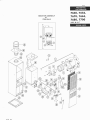
7660,7656,
7670,7663,
7680,7700
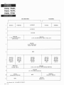
BOOSTER ASSEMBLY
for
7700 0NLY
HTG.
& A/C
2
\KY7
\(w
\ \,-/
\
l0
rcn3
421
I
8
l0
t1
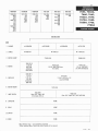
+FIRST PRODUCTION SERIAL #47OOOOO
*FIRST PRODUCTION SERIAL #174OOO
**FIRST PRODUCTION SERIAL
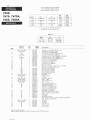
7660,
7670,7670A,
H214OOO
BTU
BTU
odel
Nat
LP
lnput
0utput
+7660
756, 856,846
759, 859, 849
60 000
48,000
+7570
*7670A
756 856 846
759, 859, 849
856
859
70,000
70 000
56,000
56,000
+7680
755 856 846
7s9 859, 849
* *7680 A
855
859
80,000
80,000
54,000
64,000
M
7680,7680A
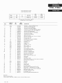
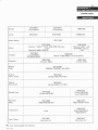
For Furnace Parts, use illustration on page 2'3
For Blower Parts, use list on page 2'7
0RtF tc Es
M
l{
ode
CODE
USED ON
MODETS
I2
7660, 7670, 7680
7670, 7680
Ail
7660 8350
Ail
7660
14
15
16
7660, 7670
7680
I1
Ail
18
19
Arl
20
Ail
Ail
2l
Ail
.22
Arl
23
All
All
24
7660
7610
7680
26
Atl
21
7660,7670, 7680
7670A, 7680A
All
7660-326 I
7660-s75 I
7670-575 I
7680 5751
7660-366 I
7550A380 I
7670-380
7560-160
7660 523
7610.523
7660A524
7670A524
7660-230
Ail
36
31
38
39
Ail
All
Ail
866s-336
7660-185
7660-520
7660-52 I
7670-520
7660-5 10
76608540
42
43
7660, 7670,7680
7550-104 r
7670A, 7680A
7570-1 04
44
45
46
Ail
41
Ail
7660-347
7660-546
7650-281
7560-547
Ail
Ail
24V (W R 1D30-303 4 wire)
Thermostat
Thermostat (W-R 1D30-339 2 wire)
Switch (on-off) (Carling MAA0A8L)
Fan Switch (C 110' 0 90' Tl2060lFl34-40)
Fan Swrtch (C-i20' 0-90' T120601C)
Transformer (115/24 V40 VA) (Basler 8E112460001)
-
-
Su b-
Base
Upper Panel (w/latch)
Panel
Upper
Lower Panel (w/latch)
Panel
Lower
Latch Assy (front panel)
Terminal Board (Molex 749-4 4l
Spud Mount (less orifice)
Panel {for air conditionrng only)
Panel (lor air conditiontng only)
Panel Assy. (for heating only)
Burner
Mounting Plate
Control Box (w/trans. & lan switch)
Control Box, upper & lower
Covers
Valve Bracket
Pilot Shield
Lighter Rod (w/chain)
Fifter (19-5/8 x 35-3/4 x l/2 lt ftller retainers are required,
order Part Number 7660-5331)
Casing Top
-
-
Atl
Atl
Ail
Atl
4i
DESCRIPTION
-
7660-183
7660-5 1 r
7660A146
7660-570
7660-340
40
I
1
Casing Top
Flue Pipe
I
I
I
lnner Rool Jack
Chimney Crown
Door Plate Assy
.Does not include gas valve
t0ode 34 replacesJ650-5201 & 7660-5211 panels on serial #773000 and above
5/74
421
1
Thermocouple (G-C 2500G24)
Bleed Line (1/8 0D)
Burner Assy. (includes Codes 17 thru 21, 36 & 40)
Note: See chart above for orilice size
(G-C 8572101)
Gas Valve
Heat Exchanger (w/gaskets)
Heat Exchanger (w/gaskets)
Heat Exchanger (w/gaskets)
Cap (w/sight glass)
Nameplate
Coleman Emblem
7670A, 7680A
All
1
I
I
7660A528 I
7660 7670, 7680
33
134
I
253 l-347
2004-1 56
30
Ail
Ail
1
I
Limit Switch (0150' C-130" T12060lLg)
Limit Switch (0155' C-135" Tl2060lL9-718)
Pilot Burner (G C 26I0306IV016)
Pilot Spud (G-C i0l045HE0l6)
Pilot Tube ( 1/4 0D Steel)
7660, 7670 7680
31
1
995 l-082
995 1-089
995 1-096
7660-359 I
7680 3591
9850A016 I
9966 0161
7650-166 I
28
29
7670A, 7680A
1
PART
NUMBER
7670-375 I
7670-395 I
7660-351 I
7660-328 I
7700 3281
7670A, 7680A
13
N0.
REQ.
LP
at
995 l-144
995 1-l 59
995 1-166
7660
7670, 7670A
7680, 7680A
7700,7700A
*FtRST PRoDUCTI0N #127 1000
+FIRST PRODUCTION #274OOO
BTU
M
odel
ilat
LP
Descri pt ion
^I
IUU
856
856
859
Heati
+77004
n
g
Heating
ony
ony
BTU
nput
0utput
100 000
100,000
80,000
80,000
I
For Furnace Parts, use illustration on page 2-3
For Blower Parts, use list on page 2-7
USED ON
MODELS
CODE
1100
N0.
R
EQ.
PART
NUMBER
19
Ail
7670-3751
7670-395 I
7660-351 I
7700-328 I
76508350 I
7700-359 1
9850A0 16 I
9966-0 16 I
7660.166 I
20
Alt
263 1-347
21
Ail
.22
Atl
2004-156
7700-528
1
Ail
995 1-1 82
I
Ail
9951 1101
1100-3261
T2
7700A
Ail
Ail
Ail
13
l4
l5
l6
Atl
I7
AI
18
Atl
I
I
24
25
26
Atl
7700-575r
All
7660 3661
tt
1100
1700
7660A380 I
7670-380
7660-160 I
7660-523 I
7700A
7670 5231
1100
7660A524
7700A
1610A5241
7660 2301
7700A
28
29
Ail
30
3l
I
2)
All
Ail
Ail
t34
All
7660 5201
Atl
7660-52 I I
7670-520 I
7660-5 10 1
7660-183 I
7660-5 I I I
7660A146 I
7550-570 1
7660-340 I
2n
All
38
36
Ail
Ail
39
Atl
40
Ail
4l
Atl
42
Ail
7700
43
Ail
Ail
Ail
Ail
Ail
Alt
All
Ail
50
51
52
7700-1 851
7660-1041
7670-1041
7660 3471
7660-547 I
4050-555 I
7660-547 I
7700-635 1
7700-3 149
8865-35 I 1
88658 128 I
7700A
44
45
46
41
48
49
866s-336 I
Ail
7700-275r
53
Atl
54
Atl
7670-509 1
8565-5701
DESCRIPTION
Thermostat
24V (W R lD30-303 4 wire)
Thermostat (W-R 1D30-339 2 wire)
Switch (on-off) (Carling MAA0A-BL)
Fan Switch (C-120' 0-90' T120601F)
Transformer llI5/24V 40VA) (Basler 8E11246001)
Limit Switch (lower) (C-135" l-165' T0D60T-11)
-
Pilot Burner (GC 26I0306TV016)
Pilot Spud (mk'd 016) (G C 1010954E016)
Pilot Iube (l/4 0D steel)
Thermocouple (G.C. 2500G24)
Bleed Line (1/8 0D)
Burner Assy (includes codes 17 thru 21, 36 & 40)
Nat. 0rifice (mkd .182)
LP 0rifice (mkd .110)
Gas Valve
(in/ouI l/21
Sub-Base
Upper Panel (w/latch)
Panel
Upper
Lower Panel (w/latch)
Panel
Lower
Latch Assembly (front panel)
Terminal Board (Molex 749-4 4l
Spud Mount (less orifice)
Panel (for air conditioning only)
Panel (for air condittoning only)
Panel Assy. (for heating only)
Mounting Plate
Burner
Covers
Control 8ox upper & lower
Valve Bracket
-
-
-
Pilot Shield
Lighter Rod (w/chain)
Filter (19-5/8 x 35-3/4 x I/2
order Part Number 7660-5331)
-
Motor Mount (rubber 4/pkg.)
Snap Switch (Robertshaw 7120)
Air Chute (pkg x 10)
Booster Relay (8665 309 RBM 84-50902 101)
*Not Shown
421
il lller retainers are required,
Casing Top
Casing Top
Flue Pipe
lnner Roof Jack
Chimney Crown
Door Plate Assembly
Booster Assembly (includes code 48 thru 52)
Booster Motor
3000 RPM (Fasco 712I-2842l'
lmpellor (3-13116 x l-1 /8 x 3/8) (Torr AA326-128)
rDoes not include gas valve
+fude 34 replaces 7560-5201 & 7660-5211 Panels on Serial #773000 and above
5/74
(G C. K47RDB58)
Heat Exchanger (w/gasket)
Cap (w/sight glass)
Na meplate
Coleman Emblem
sFIRST PRODUCTION SERIAL #1O72OOO
+FIRST PRODUCTION SERIAL #I74OOO
7656,76564,
7663,7663A
BTU
odel
Nat
tP
*7656
856
856
856
856
859
859
859
859
M
HEATING ONtY
+7656A
*7663
+7663A
BTU
nput
0utput
56,500
56,500
62,500
62 500
45,200
45,200
s0 000
50,000
I
For Furnace Parts, use illustration on page 2-3
For Blower Parts, use list on page 2-7
0RlFtc
M
USED ON
N0.
PART
MODELS
REQ.
NU M BER
T2
7656, 7663
7656A, 7663A
13
Ail
t4
All
15
Atl
16
Ail
t]
All
18
19
Ail
20
Ail
Ail
Ail
Atl
2l
.22
All
Ail
23
24
25
7656, 7656A
7663 7663A
Atl
26
27
7656, 7663
7656A, 7663A
28
Atl
29
7656, 7663
30
7656A, 7663A
7656, 7663
7656A, 7663A
3l
Ail
Ail
2?
Ail
t34
All
Ail
36
Ail
Ail
31
Ail
38
Atl
39
Atl
40
A
41
A
42
A
43
7656, 7663
7656A, 7663A
44
45
46
Ail
Ail
Ail
Ail
41
oDoes not include gas valve
995 1-136
421
I
9951-1441
995 1-0821
9951 0861
DESCRI PTION
7670-3751
7670-395 I
7660-35 1 I
7660,328 1
76608350 I
7680-359
9850A0 1 6 I
9966-0 16 1
7660-166 I
24V (W R 1D30-303 4 wire)
Thermostat
Thermostat (W-R 1D30-339 2 wire)
Switch (on-off) (Carling MAA0A-BL)
Fan Switch C-110' 0-90' T120601F134 40
Tra nsformer Il5 / 24U 40VA (Basler BE1 12460001)
263r-347 r
Thermocouple (G C 2500G24)
l/8 0D
Bleed Line
Burner Assembly (includes codes l7 thru 21, 36 & 40)
Note: See chart above lor oritice srze
Gas Valve (G C 8572101)
Heat Exchanger (w/gaskeis)
Heat Exchanger (w/gaskets)
i
2004-156 I
7560A5281
7660-326 I
7656-575 I
7660-575 I
7660-366 I
7660A380 I
7670-380
7660-160 I
7660-523
7670-523 I
7660A524 1
7610A5241
7660-230 1
8665 3361
7660-185 1
7660-520 1
7660-52 I 1
7670-520
7660-5 10 I
766085401
7660-183 I
7660-5 1 I I
7660A1461
7560-570 I
7660-340 I
i
i
7660-104
7670-104
7660-347
7660-546
7660-281
7660-547
1
I
I
I
I
I
-
Limit Switch 0-155" C-i35' T12060119'718
Pilot Burner (G-C 26T0306TV016)
Pilot Spud (G C 1010954E016)
1/4 0D steel
Pilot Tube
-
Cap (w/sight glass)
Na meplate
Coleman Emblem
Su b-Ba se
Upper Panel (w/latch)
Upper
Panel
Lower Panel (w/latch)
Lower
Panel
Latch Assembly (front Panel)
-
Terminal Board
Spud Mount (less orifice)
Panel (for air condrtroning onlY)
Panel (for air condrtioning onlY)
Panel Assy. (for heating onlY)
Burner
lvlounting PIate
Control Box (w/trans & fan switch)
Control Box uPPer & lower
Covers
Valve Bracket
Pilot Shield
Lighter Rod (w/chain)
-
-
Filter (19-3/8 x 35-3/4 x 1/4 if filter retainers are required,
order Part Number 7650-5331)
Casrng Top
Casing Top
Flue Pipe
lnner Roof Jack
Chimney Crown
Door Plate AssemblY
panels on Serial #773000 and above
tCode 34 replaces 7660-5201 & 7660-5211
5/74
LP
Nat
odel
7656, 7656A
7663, 7663A
CODE
Es
7660A590
7670A590
7680A590
7700-590
7660-6931
7680-693
7656-856
A856
-859
A859
7660-7s6
-759
-856
-859
7653-856
A856
-859
A859
7670-756
-759
-856
A856
-859
A859
7680-756
-759
-856
A856
-859
A859
7700-856
A856
-859
A859
7656-846
-849
7660.846
-849
7663.846
-849
7670.846
-849
7680-846
.849
7656,7656A,
7660,7663,
7663A,7670,
7670A,7690,
7680A,7700,
7700A
HEATII{G O]{tY
CODE
1
BLOWER
o 7660A590
2
SCROLL
.7660-537
3
MOTOR CLAMP
MOTOR
1/10
860
*8680-5391
7670-3 I
I/6
RPM
7-I/8
7700A538
l9
HP
l9
tt't-229rl'
x
9-15/16
r/4
HP,860 RPM (Fasco
7700-31 l9
HP, 1OOO RPM
(GE KSP-30KC6553S)
I
7660-387
IMPELLOR
.
o 7670-537
(Universal
DA3El90N)
5
.7700-590
o 7680A590
*7670-5391
7660-31
4
o 76704590
7670-3871
7-3/16 x l0-3/4
x
l/2
(Lau
0215s3-03-
x
t/2
(Lau 021793CA)
DD9-7AR)
6
MOTOR MOUNT
7
LIMIT SWITCH
8
CAPACITOR
NONE
9
RELAY
NONE
IO
SWITCH
NONE
II
KNOB
NONE
7670-355
I
7660-3591
7680-3791
Close 130o, Open 150'
(Thermodisc 26T-11)
.For reference only
Close
120', Open 140"
(W-R 3A03-904)
not available for shipment.
+When replacing Motor Clamp, new motor mounts will be required
-
9174
421
7656,7660,
7663,7670,
7680,7700
ArR C01{DtTto1{il{G
.7680-593
7660-6931
ACCESS0Rt ES
ll
.7660-692
.
7700-6931
7660A6901
7660-552
62 13-184 I
I/2
7660-3239
HP, 1025 RPM (Century
13370) 6.0 amp
7660-3249
l/2
HP,1075 RPM (Century 13001) 7.8 amp,
ll5
V.
7660-3601
7-3/16xl2-5/8xl/2
(Revcor F1262-700D1
NONE
7660-3591
Close 130"
Open 150"
(Thermodisc
26T-l U
7680-3i91
Close 120"
0pen 140'
7660-3591
7680-3791
7660-3591
Close 130"
Close 120"
Close
Open 150'
0pen 140'
0pen 150'
(w-R 3A03904)
(Thermodisc
(w-R 3403-
(Thermodisc
25T-1U
904)
6563-3201
7.5 mfd., 370
V.
l0
2633.3301
mfd., 370 V (Aerovox Pl64F70) (Sprague
26T-l
200Pl42ll
6313-2281
24 V SPDT (RBM 84-10103-301)
l0
710A5181
(Carling Electric 2F854-62)
1l
NONE
.For reference
917
4
421
only
not available for shipment
7660A3531
(Electron lnc. 2000-C3)
NONE
i660-3521
(Electron, lnc.)
130'
1)
BTOWER CHART
Blower
7670-6921
(3 ton-below)
7670-6931
(3 ton-below)
Scroll
o7670-637
o7670-552
7660-3249
Century 13001 % HP,
1075 RPM, 7.8 amp,
1 15V
7670-3239
Century * 13467 1* *'/rHP, 1025 RPM, 6.6 amp,
1 15V
Marathon W48A 11O512A
7670-3871
lmpellor
.8680-552
6213-1841
Motor Clamp
Motor
8680-690
7660-3601
Lau 021793CA
7-3116x10-314x%
Capacitor
Blower
Relay
R
evcor
F 1 262-7 OOD 7 -31 1 6x12-5 l9x%
2633-3301
10 mfd., 370V
6563-3201
7.5 mfd.,370V
6313-2281
RBM 84-10103-301 24V SPDT
Switch
(Cont.-Auto)
7670-3531
Carling TGAO 401-TB-B
Switch
(H eat-Cool)
Carling TGDO 411-TB-B
Resister Assy.
R
eversi ng
R
elay
Transf ormer
Term. Board
Ref .
9174
only. Not available for shipment
421
7670-3521
7670-5331
12 watt 150 OHM
7670-3091
RBM 84-50102-201
'12
8680-5331
watt 150 0HM
5 watt 200 OHM
8680-3091
RBM 184-50114-401
6282-5451
None
Basler BE8733KH
7670-350
Elec-tron, lnc.
8680-350
Elec-tron, lnc.
208/240 24V
I
8631,
8632,
8634
tP & NATURAT GAS
421