1
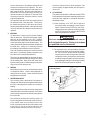
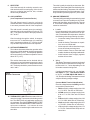
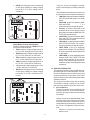
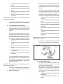
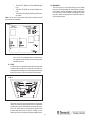
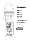
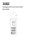
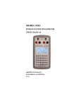
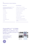
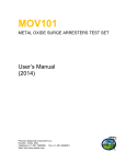
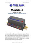
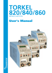
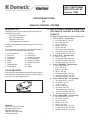
AIR CONDITIONER
BULLETIN A27-8C
October 2004
TROUBLESHOOTING
for
ANALOG CONTROL SYSTEM
A. QUICK-CHECK TROUBLE-SHOOTING
FOR ANALOG CONTROL SYSTEM COMPONENTS
INTRODUCTION
The Analog Control System can be used to operate the following Duo-Therm Units:
Roof Top Air Conditioners
Roof Top Heat Pumps
Basement Heat Pump
Other Manufacturer’s Furnaces
For detailed troubleshooting, refer to section noted.
1.
Turn to “COOL” - No Operation
a. AC Power Source - Sec. B1
b. DC Power - Sec. B2
c. Fuse - Sec. B15
d. Breaker - Sec. B16
e. Wiring - Sec. B6
f. Thermostat Cable - Sec. B12
g. Analog Thermostat - Sec. B13
h. Analog Control Box - Sec. B14
2. Turn to “OFF” - Still Operating
a. Wiring - Sec. B6
b. Thermostat Cable - Sec. B12
c. Analog Thermostat - Sec. B13
d. Analog Control Box - Sec. B14
3. Turn to “FURNACE” - No Operation
a. DC Power - Sec. B2
b. Fuse - Sec. B15
c. Breaker - Sec. B16
d. Wiring - Sec. B6
e. Thermostat Cable - Sec. B12
f. Analog Thermostat - Sec. B13
g. Analog Control Box - Sec. B4
4. Turn to “HEAT STRIP” - No Operation
a. AC Power Source - Sec. B1
b. DC Power - Sec. B2
c. Fuse - Sec. B15
d. Breaker - Sec. B16
e. Heat Strip - Sec. B9
f. Thermostat Cable - Sec. B12
g. Analog Thermostat - Sec. B13
h. Analog Control Box - Sec. B14
5. Turn to “HEAT PUMP” - No Operation
a. AC Power Source - Sec. B1
b. DC Power - Sec. B2
c. Fuse - Sec. B15
d. Breaker - Sec. B16
e. Wiring - Sec. B12
f. Thermostat Cable - Sec. B12
g. Analog Thermostat - Sec. B13
h. Analog Control Box - Sec. B14
A majority of the problems are electrical and can be found
very easily.
To find a problem in the Analog Control electrical system,
you need to be able to diagnose the following:
1.
2.
3.
4.
5.
6.
7.
8.
AC Power Source
DC Power
Compressor
Capacitors
Motors
Wiring
Reversing Valve
PTCR Device
9.
10.
11.
12.
13.
14.
15.
16.
Heat Strip
Cold Control
Outdoor Thermostat
Thermostat Cable
Analog Thermostat
Analog Control Box
Fuse
Breaker
TOOLS REQUIRED
The units can be checked with a voltmeter, ohmmeter, clampon ammeters and two good thermometers. Some clamp-on
ammeters can read voltage and ohms.
FIG. 1
REVISION
Form No. 3108373.022 10/04
(Replaces 3108373.014)
(French 3109273.015)
©2004 Dometic Corporation
LaGrange, IN 46761
1
6.
Air Conditioner/Heat Pump turned to “ON” Fan
runs, No compressor operation
a. AC Power Source - Sec. B1
b. Start Relay/PTCR - Sec. B8
c. Start Capacitor - Sec. B4
d. Fan/Run Capacitor - Sec. B4
e. Cold Control - Sec. B10
f. Outdoor Thermostat (Heat Pump) - Sec. B11
g. Compressor - Sec. B3
h. Wiring - Sec. B6
i. Thermostat Cable - Sec. B6
j. Analog Thermostat - Sec. B13
k. Analog Control Box - Sec. B14
7. Air Conditioner/Heat Pump turned to “ON”
Compressor runs, No fan operation
a. AC Power Source - Sec. B1
b. Fan/Run Capacitor - Sec. B4
c. Motor - Sec. B5
d. Wiring - Sec. B6
e. Thermostat Cable - Sec. B12
f. Analog Thermostat - Sec. B13
g. Analog Control Box - Sec. B14
8. Heat Pump turned to “ON” - Compressor and
fan run, No heat output
a. Reversing Valve - Sec. B7
b. Wiring - Sec. B6
c. Thermostat Cable - Sec. B12
d. Analog Thermostat - Sec. B13
e. Analog Control Box - Sec. B14
CAUTION
For normal operation of the unit, AC voltage
must stay between 108 VAC and 132 VAC. Operation of the unit outside of this voltage range
can result in component damage.
Make note of the wire size and length of wire. Compare it to the chart for wire sizing.
CURRENT
IN
AMPS
WIRE SIZE
16
14
12
10
8
6
LENGTH IN FEET
5
76
121
192
216
486
10
38
60
96
153
243
15
25
40
64
102
162
30
48
76
121
20
47
Removed the inside plastic air diffuser box to determine if power is reaching the unit. The junction box
will now be exposed. Remove the cover from the
junction box to gain access to the connection between the RV and the unit wires (FIG. 3). Check
with a voltmeter for voltage at the connections . USE
CAUTION as 120 volts may be present. If voltage
is not present, the problem is in the coach wiring or
breaker/fuse box.
B. DETAILED TROUBLESHOOTING FOR
ANALOG CONTROL SYSTEM COMPONENTS
2. DC VOLTAGE
A DC volt supply is required for operation of the Analog Control System. The operating range is 9 to 16
volts DC. If DC voltages are outside of the operating range, erratic operation may result.
We will now start electrically troubleshooting the Analog Control System. The best place to begin is at the
AC power source.
Use a DC voltmeter to check for the incoming DC
voltage between the red positive (+) and the black
negative (–) at the connections of the Analog Control Box. If no DC voltage is found, check the supply breaker or fuses.
1. AC POWER SOURCE
If the compressor or fan fails to operate, it is probably not receiving power. Be sure the power cord is
plugged in and no fuses or breakers are tripped.
Note: Many customers use extremely long power cords
that are undersized. If possible, ask the owner to hook up
the RV just like it was when the problem occurred.
FIG. 2
2
Check the output DC voltage from the Analog Control Box with the thermostat wires disconnected.
This can be done at the Analog Control Box wires
listed below.
a. Current Model Color Coding
Check for voltage between the GREEN (GND)
wireand:
• Tan wire for voltage ranging from 8.38 to
17.31 VDC. Fan terminal on thermostat.
• Blue wire for voltage ranging from 8.38 to
17.31 VDC. High fan terminal on thermostat.
• White wire for voltage ranging from 8.38 to
17.31 VDC. Furnace terminal on thermostat.
• Yellow wire for voltage ranging from 6.73
to 7.53 VDC. Cool terminal on thermostat.
•
•
3. COMPRESSOR
The compressor motor can be electrically checked.
Be sure to disconnect all power and turn all switches
to the “OFF” position, before starting to do the tests.
Red/White wire (labeled “TO T-STAT +7.5
SCREW) for voltage ranging from 6.74 to
7.5 VDC. +7.5 terminal on thermostat.
Orange wire (present only on heat strip or
heat pump models) for voltage ranging from
8.38 to 17.31 VDC. HS/HP terminal on thermostat.
Remove the terminal cover from the compressor to
the three leads connected to the terminals. Make
note of the positions so the wires can be replaced
correctly.
FIG. 3
Use an ohmmeter to check for continuity through
the overload device. If no continuity is found and
the compressor is hot, allow 15 to 20 minutes for
the compressor to cool. If a repeat of the test shows
the overload to be open, it is defective and requires
replacement.
Continuity should exist between all three terminals
of the compressor. If there is no continuity the compressor windings are open and the compressor is
defective.
b.
Scrape the compressor casing to bare metal and
check continuity from each terminal to the casing.
If continuity is found to the casing on any of the
terminals, the compressor is shorted and it is defective.
4. CAPACITORS
Duo-Therm Air Conditioners and Heat Pumps use
three different capacitors: 1) compressor run capacitor 2) compressor start capacitor and 3) fan/
blower capacitor. On some units the compressor
run and fan/blower capacitor are in the same case.
Early Model Color Coding
Check for voltage between the BLACK (GND
terminal on thermostat) (Unlabeled) wire and:
• Orange wire for voltage ranging from 8.38
to 17.31 VDC. Fan terminal on thermostat.
• Blue wire for voltage ranging from 8.38 to
17.31 VDC. High fan terminal on thermostat.
• White wire for voltage ranging from 8.38 to
17.31 VDC. Furnace terminal on thermostat.
• Yellow wire for voltage ranging from 6.73
to 7.53 VDC. Cool terminal on thermostat.
• Red wire (labeled “TO T-STAT +12 SCREW)
for voltage ranging from 6.74 to 7.5 VDC.
+12 terminal on thermostat.
• Violet wire (present only on heat strip or
heat pump models) for voltage ranging from
8.38 to 17.31 VDC. HS/HP terminal on thermostat.
• If a furnace is to be operated by the Analog
Control System, the furnace thermostat
leads are connected to the blue/white
striped wires out of the Analog Control Box.
The furnace wires can be connected to either wire as polarity is not important. DC
voltage is required by the Analog Control
Board on one of the two wires for furnace
operation.
The compressor run and fan/blower capacitor are
housed in a steel or aluminum case. The start capacitor is in a bake-alite shell. Some have a 15,000
ohm bleeder resistor across the terminals.
The power must be turned “OFF” and capacitors
must be discharged before making the test. Use
an AC voltmeter (set to the highest scale) or a
15,000 ohm 2 watt resistor to bleed away any
charge left in the capacitor.
Remove the wires from the terminals and inspect
the casing. If it is bulged, cracked or split, the
capacitor is defective.
Use an analog voltmeter (dial or hand reading indicator) to test the capacitor after it has been discharged. Set the ohmmeter to mid-range and check
for resistance to the case. Any resistance to the
case from the terminals indicates it is defective and
it needs to be replaced.
3
Set the ohmmeter to the highest scale and read
across the terminals on the capacitor. The ohmmeter should swing towards zero and slowly move
back towards infinity. Reverse the leads and repeat the test. If the ohmmeter stays on infinity, it is
open and needs to be replaced. If very little meter
movement is noticed, switch the meter to a lower
scale and repeat test.
Check the solenoid coil for ohms resistance. The
correct reading is approximately 465 ohm plus or
minus 10%.
8. PTCR DEVICE
The positive temperature coefficient resistor/PTCR
has replaced the compressor start relay and in some
cases the start capacitor. It should be checked in
two different ways:
The capacitors with the 15,000 ohm resistor should
be checked on the 1,000 ohm scale. The ohmmeter should swing below 15,000 ohms and return.
Reverse leads and repeat test. If the capacitor does
not act as described it is defective and needs to be
replaced.
a. Check continuity. Turn “OFF” the AC power at
the main breaker and Analog Control System
switch. Disconnect the PTCR from the circuit.
Using an ohmmeter check for continuity through
the PTCR. If there is no continuity the PTCR is
open and needs to be replaced.
5. MOTORS
To determine if a motor is good, test the windings
with an ohmmeter. Disconnect the power supply,
and turn all the switches to the “OFF” position.
Disconnect the motor leads (on some models disconnect the 6 pin plug from the electrical box). The
motor should show continuity between all leads and
the white wire. Infinity or no continuity indicates
the winding is open and the motor is defective.
! WARNING
This is an energized circuit. Shock can occur if not tested properly. Testing is to be done
by a qualified service technician.
b. The second check is an amp reading. Clamp an
ammeter around the wire from the start capacitor. Turn on the AC power and set the Analog
Control System to the cooling mode. When the
compressor starts, the ammeter should show
a reading for approximately one second. If there
is no amperage reading or a prolonged reading
the PTCR is faulty and must be replaced.
Check for continuity between the motor frame and
each lead. If a continuity reading is present to any
lead, the motor is shorted and defective.
The motor can be tested with an ammeter to determine if the operation is within the rating (±10%) listed
on the model plate. Many times the motor windings will check good, but bad bearings or capacitor
may be found in an ampere test.
FIG. 4
Continuity Check
6. WIRING
Mis-wiring or loose wires can cause electrical short
or component failure. Use the wiring diagram to
verify and correct wiring. Loose terminals should
be tightened or replaced.
7. REVERSING VALVE
The reversing valve is the heart of a heat pump. It
changes the direction of the refrigerant flow through
the coils, and changes the system from cooling to
heating.
The reversing valve’s solenoid can be energized in
either the heat or cool mode of operation. Duo-Therm
roof top heat pumps have the solenoid energized in
the cool mode.
One method of checking the reversing valve is to
feel the refrigerant line at the top of the inside coil.
In the COOL mode, this line will be cool to the
touch. In the heat mode the line will be warm or hot
to the touch. If you do not feel a cold line in the
cooling mode the direction of flow is not correct.
4
9. HEAT STRIP
Check the heat strip for continuity across the outside terminals at the heat strip plug. If the circuit is
open (no continuity) the fuse link, limit, or heater
element may be defective.
The cable is easily checked by an ohmmeter. Disconnect the Thermostat Cable from the Analog Control Box and the Analog Thermostat. No continuity
should exist between any of the conductors. Continuity indicates a problem (staple etc.) in the cable.
13. ANALOG THERMOSTAT
There are 3 different Analog thermostats being used
to control Duo-Therm Air Conditioners, Air Conditioners with Heat Strips, and Heat Pumps. The type
of Thermostat used depends on the unit and accessories used with it.
10. COLD CONTROL
(Low Temperature Protection Device)
The cold (freeze) control is used on roof top air
conditioners ONLY. If used with roof top heat pumps
it can cause premature shut off of the compressor.
11. OUTDOOR THERMOSTAT
The outdoor thermostat allows the operation of the
heat pump until the ambient (outside) temperature
drops below 40° F(± 2oF). The heat pump operation
will resume after the ambient temperature rises to
above 45° F (± 2°F).
a. Location
It is very important for the proper location of the
Analog Thermostat to ensure that it will provide a comfortable RV temperature. Observe
the following rules when selecting a location:
• Locate the Analog Thermostat 54” above
the floor.
• Install the Analog Thermostat on a partition, not on an outside wall.
• Never expose it to direct heat from lamps,
sun or other heat producing items.
• Avoid locations close to doors that lead
outside, windows or adjoining outside walls.
• Avoid locations close to supply registers
and the air from them.
The outdoor thermostat can be checked with an
ohmmeter for continuity between terminals 2 and 3
in temperatures above 45°F. In temperatures below
40°F continuity should be present between terminals 1 and 2.
b. Wiring
The Analog Thermostat is mounted on the wall
of the RV and is connected to the Analog Control Box with 6 or 7 wires depending on the
Unit and accessories being used.
The cold control is normally open (no continuity),
and closed when the temperature is below 41°F to
49°F . The switch will return to the open position at
52°F to 62°F.
Check continuity through the switch, in temperatures over 62°F it should be open (no continuity)
and in temperatures below 41°F it will be closed.
Any variation requires the switch to be replaced.
If nothing operates on the unit, turn the System Switch to “OFF”, FAN Auto/On Switch
to “AUTO”, and FAN HIGH/LOW Switch to
“LO”. Remove the Analog Thermostat cover and
verify the following voltage readings:
FIG. 5
Outdoor Thermostat
(Current Model Terminal Identification)
Check for voltage between the GND (green wire
on control box) terminal and:
• FAN terminal for voltage ranging from 8.38
to 17.31 VDC. Tan wire on control box.
• HI FAN terminal for voltage ranging from
8.38 to 17.31 VDC. Blue wire on control
box.
• FUR terminal for voltage ranging from 8.38
to 17.31 VDC. White wire on control box.
• COOL terminal for voltage ranging from 6.73
to 7.53 VDC. Yellow wire on control box.
• +7.5 terminal for voltage ranging from 6.74
to 7.5 VDC. Red with white stripe wire on
control box.
12. THERMOSTAT CABLE The thermostat cable connects the Analog Thermostat to the Analog control
box. The HEAT/COOL only application requires only
six conductors. The COOL/FURNACE/HEAT STRIP
and the COOL/FURNACE/HEAT PUMP models require seven conductors. It is common for most
manufactures to install an eight conductor thermostat cable.
5
•
If any one of the volt readings is missing,
check T-stat cable (B12) or analog control box
(B14).
HS/HP terminal (present only on heat strip
or heat pump models) for voltage ranging
from 8.38 to 17.31 VDC. Orange wire on
control box.
If the voltages shown above are present, use
a jumper wire to test unit operation as follows:
• LOW FAN, jumper wire between GND and
FAN. The unit should operate on Low fan
speed.
• HIGH FAN, jumper wire between GND,
FAN, and HI FAN.
T h e
unit should operate on high fan speed.
• Furnace, (if furnace connected to the
blue/white wires on the Analog Control
Box) jumper wire between GND and FUR.
The furnace should operate.
• LOW COOL, jumper wire between GND,
FAN, and Cool. The compressor should
operate and low fan speed.
• HIGH COOL, jumper wire between GND,
FAN, HI FAN, and COOL. The compressor should operate and high fan speed.
• HEAT STRIP, (if unit is so equipped)
jumper between GND, FAN, and HS/HP.
The heat strip should operate and the fan
on low speed.
• HEAT PUMP, (if unit so equipped) jumper
between GND, FAN, HS/HP. The heat
pump should operate on the low fan
speed. If unit operates properly when terminals are jumped, the analog thermostat
is defective.
(Early Model Terminal Identification)
Check for voltage between the GND (black wire
on control box) terminal and:
• FAN terminal for voltage ranging from 8.38
to 17.31 VDC. Orange wire on control box.
• HI FAN terminal for voltage ranging from 8.38
to 17.31 VDC. Blue wire on control box.
• FUR terminal for voltage ranging from 8.38
to 17.31 VDC. White wire on control box.
• COOL terminal for voltage ranging from 6.73
to 7.53 VDC. Yellow wire on control box.
• +12 terminal for voltage ranging from 6.74 to
7.5 VDC. Red wire on control box.
• HS/ HP terminal (present only on heat strip
or heat pump models) for voltage ranging
from 8.38 to 17.31 VDC. Violet wire on control box.
14. ANALOG CONTROL BOX
The Analog Control Box comes in 3 different configurations, that are not interchangeable. The Analog Control Board consists of several relays, plug
receptacles and other components. If any one of
these are defective the entire Analog Control Box
should be replaced.
The Analog Control Box works with the Analog
Thermostat to change or switch AC volt circuits
that control the operation of the Duo-Therm Unit.
a. Air Conditioners
To verify circuits are being completed by the
Analog Control Box, you would first disconnect the 6-pin plug connector from the Analog
Control Box.
Using a 120 volt AC incandescent Bulb, check
from terminal 5 (white-common) to the other
terminals to determine if a particular circuit is
completed through the Analog Control Box. If
the Circuit is completed the light will illuminate.
• Terminal 1 is a blue wire and the compressor circuit.
6
•
•
•
•
•
To verify circuits are being completed by the
Analog Control Box, you must first disconnect
the 6-pin plug connector from the Analog Control Box.
Terminal 2 is a black wire and the High Fan
circuit.
Terminal 3 is a yellow wire and not used.
Terminal 4 is a red wire and the Low Fan
circuit.
Terminal 5 is a white wire and the common
AC connection.
Terminal 6 is green/yellow wire and chassis ground.
Using a 120 volt AC incandescent Bulb, check
from terminal 5 (white-common) to the other
terminals to determine if a particular circuit is
completed through the Analog Control Box. If
the Circuit is completed the light will illuminate.
• Terminal 1 is a blue wire and the compressor circuit.
• Terminal 2 is a black wire and the High Fan
circuit.
• Terminal 3 is a yellow wire and reversing
valve circuit. This circuit is energized in the
cooling mode and not energized in the heat
pump mode.
• Terminal 4 is a red wire and the Low Fan
circuit.
• Terminal 5 is a white wire and the common AC
connection.
• Terminal 6 is green/yellow wire and chassis ground.
Note: DO NOT use a voltmeter to do these checks as it will
give erroneous readings.
If the circuit is completed and a component is
not operating, the problem is in the rooftop unit.
b.
Air Conditioners with Heat Strip
To verify circuits are being completed by the
Analog Control Box, you would first disconnect
the 6-pin plug connector from the Analog Control Box.
Using a 120 volt AC incandescent bulb, check
from terminal 5 (white-common) to the other
terminals to determine if a particular circuit is
completed through the Analog Control Box. If
the Circuit is completed the bulb will illuminate.
• Terminal 1 is a blue wire and the compressor circuit.
• Terminal 2 is a black wire and the High Fan
circuit.
• Terminal 3 is a yellow wire and not used.
• Terminal 4 is a red wire and the Low Fan
circuit.
• Terminal 5 is a white wire and the common
AC connection.
• Terminal 6 is green/yellow wire and chassis ground.
Note: DO NOT use a voltmeter to do these checks as it will
give erroneous readings.
If the circuit is completed and a component is
not operating, the problem is in the rooftop unit.
FIG. 6
To verify heat strip operation disconnect the 3pin plug and using a 120 volt AC Bulb, check
from terminal 1 to terminal 3. If the circuit is
completed the bulb will illuminate. To check heat
strip see Section B9.
d. Basement Heat Pump
To verify circuits are being completed by the
Analog Control Board, you must remove the
cover of the unit electrical box.
Using a 120 volt AC incandescent bulb, check
from terminal “C” (white wire) on the Fan/Run
capacitor to the terminals on the analog control board. If the circuit is completed the light
will illuminate.
• “COM” Terminal (Black) on K4 Relay120
VAC Supply.
• “NO” Terminal (Blue) on K4 Relay Compressor.
Note: DO NOT use a voltmeter to do these checks as it will
give erroneous readings.
c.
If the circuit is completed and a component is
not operating, the problem is in the rooftop unit.
Roof Top Heat Pump
7
16. BREAKER
The unit circuit is to be protected by a time delay
fuse or a HACR (heating, air conditioning, refrigerator) breaker. Take an amp draw reading at the unit’s
AC connection. If the breaker is tripping at a reading lower than its rated load, it is defective and requires replacement.
•
Terminal T1 (Black) on Control Board High
Fan.
• Terminal T2 (Red) on Control Board Low
Fan.
• Terminal “NO” (Black) on K5 Relay Reversing Valve.
Note: Do not use a volt meter to do these checks as it will
give erroneous readings.
FIG. 7
If the circuit is completed and a component is
not operating, the problem is in the component
of basement unit.
15. FUSE
A 3-amp fuse is installed in the Analog Control Box
to protect the system from shorts or overload created by disconnecting or reconnecting components,
when DC power is still connected to the system.
FIG. 8
One test is to remove the fuse and do a continuity
check. No continuity requires the fuse to be replaced.
Another test can be done without removing the fuse.
Use a DC voltmeter to check between ground and
to each side of the fuse. If there is voltage on one
side only, the fuse is bad and requires replacement.
8