1
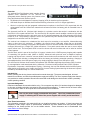
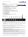
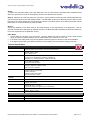
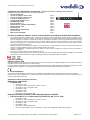
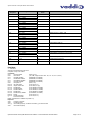
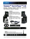
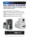
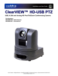
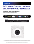
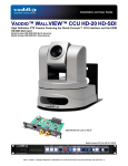
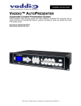
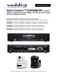
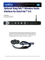
Installation and User Guide Optional EasyTalk™ Wireless Audio Interface for AutoTrak™ 2.0 Part Numbers: 999-7230-000 North America 999-7230-001 International The Optional EasyTalk AutoTrak 2.0 Wireless Audio Interface (above) works with existing AutoTrak 2.0 IR Lanyard with a built-in professional quality, unidirectional microphone mounted in the Central Medallion and the rechargeable lithium-ion battery pack and transmitter inside the Belt Pack. (The IR Lanyard and rechargeable Belt Pack are sold as part of the AutoTrak 2.0 System). ©2012 Vaddio - All Rights Reserved. Optional AutoTrak 2.0 EasyTalk Wireless Audio Interface - Document Number 342-0387 Rev B Optional AutoTrak 2.0 EasyTalk Wireless Audio Interface Inside Front Cover - Blank Optional AutoTrak 2.0 EasyTalk Wireless Audio Interface - Document Number 342-0387 Rev B Page 2 of 12 Optional AutoTrak 2.0 EasyTalk Wireless Audio Interface Overview: The optional EasyTalk Wireless Audio Interface System expands audio capabilities for the AutoTrak 2.0 Automated camera tracking system. Key features of the EasyTalk Wireless Audio Interface include: HD Wireless Link with Adaptive Frequency Hopping (AFH) for interference free operation. USB Audio Output on Wireless Audio Interface allowing connection to a PC for Skype Applications. Works in conjunction with the integrated unidirectional microphone in AutoTrak 2.0 IR Lanyard and with the rechargeable AutoTrak 2.0 Belt Pack transmitter that features a lithium-ion battery pack for extended hours of operation. The improved AutoTrak 2.0 Wireless Audio Interface is a wireless receiver that works in combination with the AutoTrak 2.0 IR Lanyard and Belt Pack. The AutoTrak 2.0 IR Lanyard’s central medallion contains a high quality unidirectional microphone and the belt pack uses an HD wireless transmitter with AFH technology that can be turned on or off. The presenter’s speech is sent to the optional EasyTALK Wireless Audio Interface specifically designed for use with the AutoTrak 2.0 System. The receiver has a balanced or unbalanced line level output for connection to an amplifier, videoconferencing codec or other room A/V equipment. In addition, the receiver has a USB audio output that can be directly connected to a PC emulating a microphone and speaker device for use with Unified Communication clients such as Skype, Microsoft Lync, Google Talk, Jabber and others. Front panel controls allow the user to mute or adjust output volume level. The back-panel GPIO is used for volume and mute functions that can be wired to external control systems. The Belt Pack, which is part of the AutoTrak 2.0 system, includes the 2.4 GHZ frequency hopping radio capable of transmitting full spectrum audio (20HZ to 20KHZ). Advanced radio protocols such as adaptive frequency hopping and forward error correction ensures reliable communication and coexistence with other devices in the band. The Belt Pack includes a rechargeable lithium-ion battery pack allowing extended operations. Charging is accomplished with a micro-USB power supply or by simply plugging it directly into a USB port on a PC. The AutoTrak 2.0 Wireless Audio Interface incorporates user selectable digital signal processing (DSP) functions to meet application needs associated with the classroom. Functions include Automatic Gain Control, Speaker Equalization, Compressor, and Microphone Filtering. Collectively, the AutoTrak Wireless Audio Interface System adds pristine sound quality to the Vaddio AutoTrak 2.0 Camera Tracking System assuring the Instructor’s speech is heard by all students locally or in remote classrooms. Intended Use: Before operating the device, please read the entire manual thoroughly. The system was designed, built and tested for use indoors, and with the provided power supply and cabling. The use of a power supply other than the one provided or outdoor operation has not been tested and could damage the device and/or create a potentially unsafe operating condition Important Safeguards: Read and understand all instructions before using. Do not operate any device if it has been dropped or damaged. In this case, a Vaddio technician must examine the product before operating. To reduce the risk of electric shock, do not immerse in water or other liquids and avoid extremely humid conditions. Use only the power supply provided with the system. Use of any unauthorized power supply or extending the DC side of the power supplies will void any and all warranties. Save These Instructions: The information contained in this manual will help you install and operate your product. If these instructions are misplaced, Vaddio keeps copies of Specifications, Installation and User Guides and most pertinent product drawings for the Vaddio product line on the Vaddio website. These documents can be downloaded from www.vaddio.com free of charge. Optional AutoTrak 2.0 EasyTalk Wireless Audio Interface - Document Number 342-0387 Rev B Page 3 of 12 Optional AutoTrak 2.0 EasyTalk Wireless Audio Interface Unpacking: Carefully remove all of the parts for the Optional EasyTalk Wireless Interface for the AutoTrak 2.0 from the packaging. The System 999-7230-000 for North America includes: One (1) 998-7230-000 EasyTalk AutoTrak 2.0 Wireless Audio Receiver One (1) 2.39GHZ-2.51GHz ½-Wave, 3.5” RP-SMA Right Angle, Antenna Two (2) 342-0341 Rack Ears 12 VDC, 1 Amp Power Supply with North American Power Cord One (1) 6’ (1.83m) USB 2.0 Cable Type A-Male to Type B-Male Manual (Installation and User Guide) The System 999-7230-001 for International use includes: One (1) 998-7230-000 EasyTalk AutoTrak 2.0 Wireless Audio Receiver One (1) 2.39GHZ-2.51GHz ½-Wave, 3.5” RP-SMA Right Angle, Antenna Two (2) 342-0341 Rack Ears 12 VDC, 1 Amp Power Supply One (1) Euro Power Cord One (1) One UK Power Cord One (1) 6’ (1.83m) USB 2.0 Cable Type A-Male to Type B-Male Manual (Installation and User Guide) The Front Panel Controls: ① ② ③ ④ ⑤ ⑥ ⑦ 1) Power ON/OFF: This switch turns the power for the AutoTrak 2.0 Wireless Audio Interface on or off. button’s blue LED is lit, the system is on ready for operation. 2) Pair: This button initiates the automatic pairing for the Belt Pack Radio Transmitter and the AutoTrak 2.0 Wireless Audio Interface Receiver. Pairing is the matching of the same Adaptive Frequency Hopper (AFH) sequence for both devices. 3) Mute: This control mutes (turns off) the audio outputs of the AutoTrak 2.0 Wireless Audio Interface. 4) Volume: The + (plus) and – (minus) buttons are used to raise and lower the audio outputs (Balanced and Unbalanced) from the AutoTrak 2.0 Wireless Audio Interface. 5) Audio Level: This LED display ladder will indicate the relative audio level output (from all sources) of the AutoTrak 2.0 Wireless Audio Interface. The red line at the top of the display indicates clipping. 6) Radio, EQ Filter and Compressor Status LED’s: Radio LED: Solid blue light indicates normal operation. Fast flashing indicates no link established with the Belt Pack Wireless Microphone. Slow flashing indicates the Pairing cycle is in progress. EQ Filter: Blue light on indicates the EQ Filter is turned on. Blue light off indicates the EQ Filter is off. When EQ Filter is enabled, it helps increase speaker intelligibility for voice applications. Compressor: Solid blue indicates that the Compressor is on. No light indicates that the Compressor is off. The Compressor minimizes the potential of “clipping” by attenuating the audio signals that exceed the maximum input. 7) When the Antenna: The antenna is tuned to receive 2.4 GHZ signals from the IR Lanyard Belt Pack Microphone. Note: If the AutoTrak 2.0 Wireless Audio Interface is installed deep inside a metal equipment rack or is surrounded by other metal cased equipment, the antenna may need to be extended away from the rack to improve reception. Optional AutoTrak 2.0 EasyTalk Wireless Audio Interface - Document Number 342-0387 Rev B Page 4 of 12 Optional AutoTrak 2.0 EasyTalk Wireless Audio Interface The Rear Panel Connections: ① ② ③ ④ ⑤ ⑥ ⑦ 1) 12 VDC, 1.0 Amp Power Connector: The 5.5mm OD and 2.5mm ID coaxial power connector should be plugged into the PowerRite power supply provided by Vaddio. Use of any unauthorized power supplies will void any and all warranties. 2) rd RS-232 Control: The DE-9 female (DB-9 for conventionalists) connector is provided for 3 party control systems using the Wireless Audio Interface Application Protocol Interface (API). See the Command List in Appendix A.. 3) Settings (8-Position Dip Switch): The eight position dip switch is used for system configuration of the AutoTrak 2.0 Wireless Audio Interface: Dip Switch # 1 2 3 4 5 6 7 8 Function ON/OFF - Enable/Disable - Compressor for the Balanced and Unbalanced Audio Outputs ON/OFF - Enable/Disable - Speaker EQ Filter ON/OFF - USB Conference Mode (Skype-type PC applications) ON/OFF - ON Enables Radio, OFF Disables Radio ON/OFF - Baud Rate Selection: 9600-Off/38.4K-On (Use 9600bps for most all applications) ON/OFF - Front Panel Locked Out when ON ON/OFF - ON allows full Serial control bypassing dip switches 1, 2, 3, 4, and 8 Not Used Dip Switch 1 - Compressor: Enable adds a Dynamic Range Compressor for the Audio Line Level Outputs (balanced or unbalanced). Disable turns it off. Dip Switch 2 - Speaker EQ Filter: Enable adds a specialized output filter for improved intelligibility for voice applications. Disable turns it off. Dip Switch 3 - ON Position/USB Conference Mode: Enable (Dip Switch 3 On) creates the desired audio mixing (Near and Far ends) for USB conferencing applications such as Skype, Jabber, Lync etc… In the USB Conference Mode, the PC USB Speaker Audio is sent to the balanced and unbalanced audio line outputs, which allows the Far End Audio to be presented in the room. The Belt Pack Wireless Microphone Audio is also sent to the PC and the Far End. The AutoTrak 2.0 Wireless Audio Interface will also be recognized as a USB Audio Device by the PC with recording (the Belt Pack Wireless Microphone Audio) and playback (the Speaker Audio) capabilities. Disable turns the USB Conference Mode off. Dip Switch 3 - OFF Position/USB Record Mode: Disable (Dip Switch 3 Off) creates a USB Record Mode for PC Audio Recording (PC requires Audio Recording Software-not included) and Playback through the USB port (Audio output through the Balanced or Unbalanced Audio Line Outputs). The AutoTrak 2.0 Wireless Audio Interface will be recognized as a USB Audio Device by the PC with recording (the Belt Pack Wireless Microphone Audio) and playback (the Speaker Audio) capabilities. Dip Switch 4 - Radio ON/OFF: ON enables the Radio Receiver for the Wireless Microphone on. OFF turns it off, naturally. Dip Switch 5 - Baud Rate Selection ON/OFF: OFF sets the Baud Rate to the default 9600bps. ON sets the Baud Rate to 38400bps. For most applications 9600bps will do. Dip Switch 6 - Front Panel Buttons Lock ON/OFF: ON locks the Front Panel Buttons and disables the buttons from functioning. OFF allows the front panel buttons to be used. Dip Switch 7 - Software Control ON/OFF: When ON, dip switches 1, 2, 3, 4, and 8 are ignored to allow full serial control of the audio interface Dip Switch 8 - Resets to Factory Defaults ON/OFF: When ON and power is plugged in, the interface is set to factory defaults. Leave OFF for normal operation. Optional AutoTrak 2.0 EasyTalk Wireless Audio Interface - Document Number 342-0387 Rev B Page 5 of 12 Optional AutoTrak 2.0 EasyTalk Wireless Audio Interface 4) GPIO Port: The GPIO Port provides the ability to interface with external control systems. Inputs are logic level low. Outputs are open collectors. Pin 1 2 3 4 5 6 7 5) Function Power (12 VDC) Mute Toggle (Input) Mute Status (Output) Volume Up (Input) Volume Down (Output) Not Used Ground USB Type B Connector: This connector is used to interface with the Host PC for soft-client codec type applications. 6) Audio Outputs: There are two (2) Audio Outputs on the rear panel: Balanced Audio Output Jack: Balanced Line Level (on XLR - M connector) +4dBu Unbalanced Audio Output Jack: Unbalanced Line Level (on RCA-F connector) -10dbV Step by Step Instructions for setting up the AutoTrak 2.0 Wireless Audio Interface: Step 1: Have a certified AutoTrak 2.0 installer set-up and install the AutoTrak 2.0 according to the AutoTrak 2.0 manual. Step 2: Take the AutoTrak 2.0 Wireless Audio Interface Receiver out of the box (typical in most installations). Step 3: Review the manual to eliminate any and all surprises. Step 4: Connect the 3.5” right-angle RP-SMA antenna to the front of the receiver and connect the power supply. Step 5: Connect the audio outputs (Balanced, Unbalanced or USB) to the audio system (not included). Set all audio levels on the audio system low to avoid any rude awakenings. Step 6: The Audio Interface Receiver works in conjunction with the mic element in the AutoTrak Lanyard’s Central Medallion and the Belt Pack. On the Belt Pack, turn the System Power and the Microphone switches to the ON position. Power and Mic Switches Step 7: Touch the Power button on the Audio Interface and the back-lit blue LED power switch will illuminate. Step 8: To “Pair” the Belt pack with the Receiver, carefully press down at the top of the removable battery cover near the center of the small opening and slide the cover downward. Switch #3, marked SW3 on the circuit board next to the battery is the pairing button (see figure on the right). Place the Belt Pack in close proximity to the AutoTrak 2.0 Wireless Audio Interface. Press the SW3 button and release. The Radio LED on the Belt Pack front panel will begin blinking at a slow rate. Press the Pair Button on the front panel of the AutoTrak 2.0 Wireless Audio Interface. The Belt Pack and the AutoTrak 2.0 Wireless Audio Interface will automatically sync with each other. The blue Radio LED’s on the Belt Pack and the AutoTrak 2.0 Wireless Interface front panels will illuminate solid blue indicating they are paired and ready for operation SW5 SW4 SW3 Important Note: The Pairing button on the AutoTrak 2.0 Wireless Audio Interface must be pushed within ten (10) seconds of pressing the pairing button SW3 on the Belt Pack or pairing will not occur. Optional AutoTrak 2.0 EasyTalk Wireless Audio Interface - Document Number 342-0387 Rev B Page 6 of 12 Optional AutoTrak 2.0 EasyTalk Wireless Audio Interface Step 9: To replace the removable battery cover, start sliding the cover on at the bottom of the battery pack compartment and slide cover upward to the top of the small opening until the cover latches back into place. Step 10: Adjust the mic volume by using the + (plus) and – (minus) buttons on the front panel of the Wireless Receiver and set the audio levels on the audio system to taste. The LED ladder will act as an LED meter and as a way to set the levels when the volume buttons are touched and held. Test the mic ON/OFF switch on the Belt Pack and also the Mic Mute switch on the Audio Interface for proper operation. Step 11: Set the Dip Switches on the Back Panel of the Audio Receiver for the requirements of the application. See the AutoTrak 2.0 Manual for setting the dip switches internal to the Belt Pack (SW4 and SW5) and set these switches on the for the requirements of the application as well. Other Notes: The IR LEDs can’t be seen (if you are human - since the 850nm LED light is outside of human optical sensory range) so make sure that the System Power on the Belt Pack Unit is off when it is not in use. If the Audio Level output is set to a high level, please avoid touching the mic element on the central medallion. If the System Power LED on the Belt Pack flashes, then the battery is low and a battery change is required. Technical Specifications AutoTrak Wireless Audio Interface Part Numbers AutoTrak Wireless Audio Interface 998-7230-000 (North America) AutoTrak Wireless Audio Interface 998-7230-001 (International) Audio Specifications Frequency Respones:20 HZ to 20KHZ Dynamic Range: >75dB THD + Noise: <.02% Analog Line Output Connector: XLR (Balanced) & RCA (Unbalanced) Impedance: 50 ohm (Balanced) & 10Kohm (Unbalanced) Nominal Level: +4dBu (Balanced) & -10dBu (Unbalanced) USB Audio Interface Connector: Type B Male Type: USB 2.0 Compliant PC Controls: Mute & Volume Microphone Type: Unidirectional Condenser Microphone Frequency Response: 100HZ to 12KHZ Max Input Level: 115dB SPL Radio Link Type: Adaptive Frequency Hopping Frequency Range: 2400 to 2483 Antenna: Monopole Maximum Power Output: 5dBm Receiver Sensitivity: -83dBm Audio Processing 8-Position Dip Switch for Compressor, Speaker EQ Filter, Mix Mode Settings User Controls Power Button, Volume Up/Down, Microphone Mute, Pairing Button, LED Indicators, VU Meter GPIO Inputs: Mute Control, Volume Up, Volume Down (Active Logic Low) Outputs: Mute Status Belt Pack Battery Type:4400mAH Lithium Ion Typical Talk Time : > 18 hours Typical Full-Charge Time: @ 9hours (from dead battery) Receiver Power Supply Connector: 5.5mm OD X 2.5mm ID coax receptacle Supply: 12VDC, 1.0 Amp Serial Control Protocol RS-232 (Firmware Updates & ASCII Control) General Information Operating Temperature 32° to 104° F (0° to 40° C) Power Consumption Maximum 12 watts Dimensions (H x W x D) 1.72” (43.68mm) H X 18.93” (480.82mm) W X 6” (152.4mm)D with rack ears attached Weight 3.3 lbs. (1.5 kg) Optional AutoTrak 2.0 EasyTalk Wireless Audio Interface - Document Number 342-0387 Rev B Page 7 of 12 Optional AutoTrak 2.0 EasyTalk Wireless Audio Interface Compliance and CE Declaration of Conformity: EasyTalk AutoTrak 2.0 Wireless Audio Interface Compliance testing was performed to the following regulations: FCC Part 15 Subpart B FCC Part 15, Subpart C Section 15.247 FCC Part 15, Subpart C Section 15.207 Industry Canada RSS-210 Issue 8 Industry Canada RSS-Gen Issue 3 Class A Class A Class A Class A IEC 60950-1/A1: 2009 Safety ETSI EN 300 328 V1.7.1 EN 55022 A: 2010 (CISPR 22, 2008, Modified) ICES-003, Issue 4: 2004 EN 55022 A: 2010 AS/NZS CISPR 22: 2009 +A1:2010 VCCI V-3/2011.04 EMC Directive 2004/108/EC Class A Class A Class A Class A Class A Class A Class A FCC Part 15 Subpart B, Subpart C, Section 15.249 Compliance and Industry Canada RS-210 Compliance This equipment has been tested and found to comply with the limits for a Class A digital device, pursuant to Part 15, Subpart C of the FCC Rules and RS-210 of Industry Canada. These limits are designed to provide reasonable protection against harmful interference when the equipment is operated in a commercial environment. This equipment generates, uses, and can radiate radio frequency energy and, if not installed and used in accordance with the instruction manual, may cause harmful interference to radio communications. Operation of this equipment in a residential area is likely to cause harmful interference in which case the user will be required to correct the interference at his/her own expense. Operation is subject to the following two conditions: (1) This device may not cause interference, and (2) This device must accept any interference including interference that may cause undesired operation of the device. Changes or modifications not expressly approved by Vaddio can affect emission compliance and could void the user’s authority to operate this equipment. Do not use any antenna other than the one provided on the unit. This equipment complies with the FCC/IC radiation exposure limits set forth for portable transmitting devices operating in an uncontrolled environment. End users must follow the specific operating instructions for satisfying RF exposure compliance ICES-003 Compliance ICES-003, Issue 4: 2004 This digital apparatus does not exceed the Class B limits for radio noise emissions from digital apparatus set out in the Radio Interference Regulations of the Canadian Department of Communications. Le présent appareil numérique n’emet pas de bruits radioélectriques dépassant les limites applicables aux appareils numeriques de la classe B préscrites dans le Règlement sur le brouillage radioélectrique édicte par le ministère des Communications du Canada. European Compliance This product has been evaluated for Electromagnetic Compatibility under the EMC Directive for Emissions and Immunity and meets the requirements for a Class A digital device. In a domestic environment this product may cause radio interference in which case the user may be required to take adequate measures. Standard(s) To Which Conformity Is Declared: EMC Directive 2004/108/EC EN 55024: 2010 EN 61000-4-2: 2009 EN 61000-4-3: 2006 + Amendments A1: 2008 + A2: 2010 EN 61000-4-4: 2004 + Corrigendum 2006 EN 61000-4-5: 2006 EN 61000-4-6: 2009 EN 61000-4-8: 2010 EN 61000-4-11 Second Edition: 2004 Radio and Telecommunications Terminal Equipment Directive 1999/5/EC ETSI EN 301 489-17 V2.1.1: 2009 referencing ETSI EN 301 489-1 V1.2.1: 2008 EN 61000-4-2: 2009 EN 61000-4-3: 2006 + Amendments A1: 2008 + A2: 2010 EN 61000-4-4: 2004 + Corrigendum 2006 EN 61000-4-5: 2006 EN 61000-4-6: 2009 EN 61000-4-11 Second Edition: 2004 ISO 7637-2 Second Edition: 2004 + Amendment A1: 2008 - Test not applicable for base station equipment Optional AutoTrak 2.0 EasyTalk Wireless Audio Interface - Document Number 342-0387 Rev B Page 8 of 12 Optional AutoTrak 2.0 EasyTalk Wireless Audio Interface Warranty Information: (See Vaddio Warranty, Service and Return Policies posted on vaddio.com for complete details): Hardware* Warranty: One year limited warranty on all parts. Vaddio warrants this product against defects in materials and workmanship for a period of one year from the day of purchase from Vaddio. If Vaddio receives notice of such defects during the warranty period, they will, at their option, repair or replace products that prove to be defective. Please see Vaddio’s Service Terms and Conditions at vaddio.com for specific details and policies. Exclusions: The above warranty shall not apply to defects resulting from: improper or inadequate maintenance by the customer, customer applied software or interfacing, unauthorized modifications or misuse, operation outside the normal environmental specifications for the product, use of the incorrect power supply, improper installation (plugging things in wrong), improper extension of the power supply cable or improper site operation and maintenance. Vaddio Customer Service: Vaddio will test, repair, or replace the product or products without charge if the unit is under warranty and is found to be defective. If the product is out of warranty, Vaddio will test then repair the product or products. The cost of parts and labor charge will be estimated by a technician and confirmed by the customer prior to repair. All components must be returned for testing as a complete unit. Vaddio will not accept responsibility for shipment after it has left the premises. Vaddio will only advance replace out of box failures or random equipment failures up to 30 days after the purchase date (not the install date). Vaddio Technical Support: Vaddio technicians will determine and discuss with the customer the criteria for repair costs and/or replacement. Vaddio Technical Support can be contacted through one of the following resources: e-mail support at [email protected] or online at www.vaddio.com. Return Material Authorization (RMA) Number: Before returning a product for repair or replacement, request an RMA from Vaddio’s technical support. Provide a technician with a return phone number, e-mail address, shipping address, and product serial numbers and describe the reason for repairs or returns as well as the date of purchase and proof of purchase. Include your assigned RMA number in all correspondence with Vaddio. Write your assigned RMA number on the clearly on the shipping label when returning the product. All products returned for credit are subject to a restocking charge without exception. Voided Warranty: The warranty does not apply if the original serial number has been removed or if the product has been disassembled or damaged through misuse, accident, modifications, or unauthorized repair. Cutting the power supply cable on the secondary side (low voltage side) to extend the power to the device (camera or controller) voids the warranty for that device. Shipping and Handling: Vaddio will not pay for inbound shipping transportation or insurance charges or accept any responsibility for laws and ordinances from inbound transit. Vaddio will pay for outbound shipping, transportation, and insurance charges for all items under warranty but will not assume responsibility for loss and/or damage by the outbound freight carrier. If the return shipment appears damaged, retain the original boxes and packing material for inspection by the carrier. Contact your carrier immediately. Products Not Under Warranty: Payment arrangements are required before outbound shipment for all out of warranty products. *Vaddio manufactures its hardware products from parts and components that are new or equivalent to new in accordance with industry standard practices. Other General Information: Care and Cleaning Do not attempt to take this product apart at any time. There are no user-serviceable components inside. Do not spill liquids in the product Keep this device away from food and liquid For smears or smudges on the product, wipe with a clean, soft cloth Use a lens cleaner on the lens Do not use any abrasive chemicals. Operating and Storage Conditions: Do not store or operate the device under the following conditions: Temperatures above 40°C (104°F) or temperatures below 0°C (32°F) High humidity, condensing or wet environments In inclement weather In costal estuaries, dry river beds or house boat Dry environments with an excess of static discharge Under severe vibration Optional AutoTrak 2.0 EasyTalk Wireless Audio Interface - Document Number 342-0387 Rev B Page 9 of 12 Optional AutoTrak 2.0 EasyTalk Wireless Audio Interface Appendix 1: Pin-outs and Stuff RS-232 Control: DE-9 Female (DB-9 for convention): Communication Specification Communication Speed: 9600 bps or 38,400 Stop bit: 1 Data bits: 8 Parity: None No Flow control Control Port - RS-232 on DE-9 Female Connector PIN# Signal 2) TXD 3) RXD 5) GND All other pins - Unused AutoTrak II Audio User Serial Command Set: The EasyTalk AutoTrak 2.0 Wireless Audio Interface has an RS-232 command interface for configuration and real-time control. This interface can be used interactively with a serial terminal emulator, or through a scripted interface without terminal emulation (command echo and prompt). DIP switch 7 on the Receiver unit controls whether configuration commands are enabled on the serial interface (switch in the up position), or whether the configuration is controlled exclusively from the DIP switches (switch in the down position). Real-time control commands are always available over the serial port. Command echo and prompt can be enabled or disabled with the 6121 command. When enabled, commands input to the receiver are echoed back, and a '>' prompt character is output whenever a carriage return is entered. When disabled the echo and prompt characters are suppressed. For all commands, the termination character is a carriage return (hex 0D). Response strings output by the Receiver will end with both a carriage return and a line feed (hex 0A). Input line feed characters are ignored. “Set” commands return one of three responses: OK (4100), bad command (4199), or bad parameter (4198). “Get” commands return a response string indicating the command being responded to and the data requested. The format of a “get” response is a 4-digit response code, a space, and a two-digit hex value Command Set Table: Command Response 5101 4101 Argument 5102 none 00 – off 01 – on none 4102 nn 5110 4110 none 00 – disabled 01 – enabled none 00 – disabled 01 – enabled 5111 4111 Available w/ DIP 7 Down Y n/a Description Get mute status Mute status response Y Get volume Y n/a Volume response where nn is: FB : -5 dB FC : -4 dB … FF : -1 dB 00 : 0 dB … 29 : 29 dB Get compressor enabled Compressor enabled response Y n/a Get filter enabled Filter enabled response Optional AutoTrak 2.0 EasyTalk Wireless Audio Interface - Document Number 342-0387 Rev B Page 10 of 12 Optional AutoTrak 2.0 EasyTalk Wireless Audio Interface Command Response 5112 4112 Argument Available w/ DIP 7 Down Y n/a Description Get mixer enabled Mixer enabled response Y n/a Get radio enabled Radio enabled response Y n/a Get power enabled Power enabled response Y Set mute on or off Y Adjust volume by +1dB or -1dB N Enable/disable compressor N Enable/disable filter N Enable/disable USB mix N Enable/disable radio N Y Y Reset to factory default settings Power on/off Enable/disable command echo and prompt n/a Command complete response 4100 none 00 – disabled 01 – enabled none 00 – disabled 01 – enabled none 00 – disabled 01 – enabled 00 – off 01 – on 00 – down 01 – up 00 – disabled 01 – enabled 00 - disabled 01 – enabled 00 – disabled 01 – enabled 00 – disabled 01 – enabled 01 00 – off 00 – disabled 01 – enabled none 4198 none n/a Invalid argument response 4199 none n/a Invalid command response 5113 4113 5120 4120 6101 6102 6110 6111 6112 6113 6114 6120 6121 Help Menu: >? - This Menu AutoTrak 2.0 Audio Receiver V01.00.04 Compiled: 12-Apr-12 at 15:38:51 Commands: 5101 - Get mute status (00-off, 01-on) 5102 - Get volume (-16, 0 dB, 2-digit hex value: f0 is -16, f1 is -15, ff is -1, 00 is 0) 5110 - Get DRC enabled (00-disabled, 01-enabled) 5111 - Get EQ filter enabled (00-disabled, 01-enabled) 5112 - Get USB mix enabled (00-disabled, 01-enabled) 5113 - Get radio enabled (00-disabled, 01-enabled) 5120 - Get power on (00-off, 1-on) 6101 xx - Set mute status (xx: 00-off, 01-on) 6102 xx - Adjust volume 1dB (xx: 00-down, 01-up) 6110 xx - Enable DRC (xx: 00-disable, 00-enable) 6111 xx - Enable EQ filter (xx: 00-disable, 01-enable) 6112 xx - Enable USB mix (xx: 00-disable, 01-enable) 6113 xx - Enable radio (xx: 00-disable, 01-enable) 6114 xx - Enable factory defaults (x: 00-disable, 01-enable) 6120 xx - Power (xx: 00-off, 01-on) 6121 xx - Enable serial echo (xx: 00-off, 01-on) ? - Print command list NOTE: commands 611x available only if DIP 7 up Reponses: 4199 - Unknown command 4198 - Invalid argument 41xx yy - Successful get (5xxx), xx matches command, yy is returned value 4100 - Successful set (6xxx) Optional AutoTrak 2.0 EasyTalk Wireless Audio Interface - Document Number 342-0387 Rev B Page 11 of 12 Optional AutoTrak 2.0 EasyTalk Wireless Audio Interface 9433 Science Center Drive, Minneapolis, MN 55428 Toll Free: 800-572-2011 ▪ Phone: 763-971-4400 ▪ FAX: 763-971-4464 www.vaddio.com ©2012 Vaddio - All Rights Reserved. Reproduction in whole or in part without written permission is prohibited. Specifications and pricing are subject to change without notice. Vaddio, AutoTrak, and EasyTalk, are trademarks of Vaddio. All other trademarks are property of their respective owners. Document 342-0387 Rev. B Optional AutoTrak 2.0 EasyTalk Wireless Audio Interface - Document Number 342-0387 Rev B Page 12 of 12