1
IO-520
CONTINENTAL® AIRCRAFT ENGINE
OVERHAUL
MANUAL
TECHNICAL CONTENT ACCEPTED BY THE FAA
Publication X30039
©
2011 CONTINENTAL MOTORS, INC.
AUG 2011
Supersedure Notice
This manual revision replaces the front cover and list of effective pages for Publication Part No. X30039, dated
September 1977. Previous editions are obsolete upon release of this manual.
Effective Changes for this Manual
0 .......... September 1977
1 ............ 31 August 2011
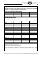
List of Effective Pages
Document Title: IO-520 Series Engine Overhaul Manual
Publication Number: X30039
Page
Change
Page
Change
Initial Publication Date: September 1977
Page
Change
Page
Change
Cover............................ 1
A................................... 1
i thru v .......................... 0
1-1 thru 1-10................. 0
2-1 thru 2-10................. 0
3-1 thru 3-2................... 0
4-1 thru 4-30................. 0
5-1 thru 5-12................. 0
6-1 thru 6-30................. 0
7-1 thru 7-8................... 0
8-1 thru 8-20................. 0
9-1 thru 9-8................... 0
10-1 thru 10-2............... 0
Published and printed in the U.S.A. by Continental Motors, Inc.
Available exclusively from the publisher: P.O. Box 90, Mobile, AL 36601
Copyright © 2011 Continental Motors, Inc. All rights reserved. This material may not be reprinted, republished, broadcast, or otherwise
altered without the publisher's written permission. This manual is provided without express, statutory, or implied warranties. The publisher will
not be held liable for any damages caused by or alleged to be caused by use, misuse, abuse, or misinterpretation of the contents. Content is
subject to change without notice. Other products and companies mentioned herein may be trademarks of the respective owners.
A
IO-520 Series Engine Overhaul Manual
31 August 2011
i
iv October 1978
October 1978 v
Intentionally Left Blank
SECTION I
INTRODUCTION
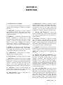
1-1. SCOPE. This publication comprises
Overhaul Instructions for the IO-520 Series Aircraft
Engines.
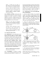
1-5. CYLINDER ARRANGEMENT. Cylinders
are numbered starting from the rear, with odd
numbers on the right and even numbers on the left.
1-2. RELATED PUBLICATIONS. Detail part
numbers and service assemblies for these engine
models are contained in Parts Catalog X-30040A.
Operating instructions are contained in Operator's
Handbook X-30041.
1-6.
a. Service instructions for Slick Magneto Model
No. 662 may be obtained from Slick Electro Inc.,
Rockford, Illinois 61100.
b. Service instructions for Bendix Magneto
Model S6RN-201, S6RN-205, S6RN-1201 and
S6RN-1205 may be obtained from Bendix
Corporation, Electrical Components Division,
Sidney, New York 13830.
c. Service instructions for Delco-Remy Starters,
Generators or Alternators may be obtained from
Delco-Remy Division, General Motors Corporation,
Anderson, Indiana 96011.
1-3.
SERVICE
BULLETINS.
Important
changes and product improvements are covered by
factory service bulletins available for study at all
Approved Distributors. These Bulletins are also
available to owners, operators or maintenance
personnel on an annual subscription basis.
1-4.
SERVICE REPORTS AND INQUIRIES.
It is the policy of Teledyne Continental Motors to
handle all reports of service difficulty and requests
for information through Approved Distributors.
Request for further copies of this or any other
Teledyne Continental Aircraft Engine Service
Publication should be made through these facilities.
There is an Approved Distributor at every major
airport.
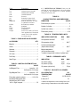
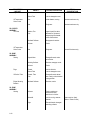
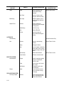
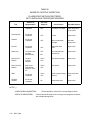
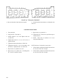
DEFINITIONS AND ABBREVIATIONS
Term .
A.B.C.
Approx.
A.T.C.
Bar.
B.B.C.
B.H.P.
B. T.C.
F.A.A.
C.A.R.
c.f.m.
C.G.
Dia.
°
°F.
Fig.
Front
ft.
G.P .M.
H2O
Hg.
I.D.
in. (")
Hex.
hr.
Left Side
Lbs.
Lockwire
Man.
Max.
Min.
30'
N.P.T.
Explanation
After Bottom Center
Approximately
After Top Center
Barometric
Before Bottom Center
Brake horsepower
Before Top Center
Federal Aviation Administration
Civil Air Regulations
Cubic feet per minute
Center of Gravity
Diameter
Degrees of Angle
Degrees Farenheit
Figure (Illustration)
Propeller End
foot or feet
Gallons per minute
Water
Mercury
Inside Diameter
Inches
Hexagon
Hour
Side on which Nos. 2, 4 and
6 cylinders are located
Pounds
Soft steel wire used to safety
connections, etc.
Manifold or manometer
Maximum
Minimum
thirty minutes of angle
(60' equal one degree)
National pipe thread
(tapered)
MAY 1980
1-1
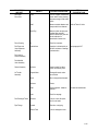
Term .
Explanation
N.C.
N.F.
O.D.
Press.
p.s.i.
Rear
Right Side
National Coarse (thread)
National Fine (thread)
Outside Diameter
Pressure
Pounds per square inch
Accessory end of engine
Side on which Nos. 1, 3 and
5 cylinders are located
Revolution per minute
Standard
Top dead center
Temperature
Force x lever arm (125 ft.-lbs.
force applied one ft. from bolt
center or 62-1/2 lbs. applied
2 ft. from center)
R.P.M.
Std.
T.D.C.
Temp.
Torque
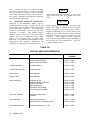
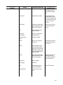
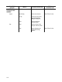
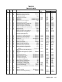
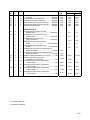
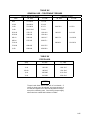
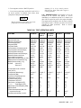
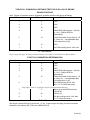
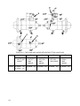
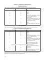
TABLE I. PURCHASED ACCESSORIES
ACCESSORY
QTY
Magneto .......................................................................2
Starter ..........................................................................1
Alternator .....................................................................1
Generator.....................................................................1
Oil Cooler .....................................................................1
Fuel Pump....................................................................1
Spark Plugs................................................................12
TABLE II. IGNITION SYSTEM DETAILS
FEATURE
VALUE
Left Magneto Fires ............................... Lower No. 1-3-5
And Upper No. 2-4-6 plugs
Right Magneto Fires............................. Upper No. 1-3-5
And Lower No. 2-4-6 plugs
1-7. DEFINITION OF TERMS. Front, rear, left
and right, as used in this manual, refer to the engine
as viewed by the mechanic in a normal position,
facing the accessory end.
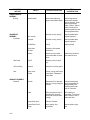
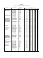
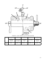
TABLE III.
CHARACTERISTICS AND DIMENSIONS
DIMENSION
Piston stokes per cylinder ............................................4
Number of cylinders .....................................................6
Cylinder bore (inches).............................................5.25
Piston stroke (inches) .............................................4.00
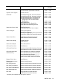
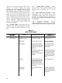
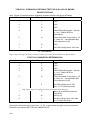
TABLE IV. TEMPERATURE LIMITS
INDICATED CONDITION
MIN.
MAX.
Oil temperature at takeoff
75°F
--
Oil temperature in flight
--
240°F.
Cylinder head temperature
(bayonet thermocouple)*
--
460°F.
Magneto temperature
(at coil hold-down screw)
--
170°F.
* Installed in tapped hole in bottom of cylinder head.
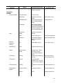
TABLE V. PRESSURE LIMITS
INDICATION
MIN.
MAX.
Oil pressure (idling)
10 psi
--
Oil pressure (in flight)
30 psi
60 psi
--
100 psi
Oil pressure (with cold oil)
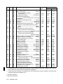
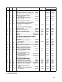
TABLE VI. VISCOSITY OIL GRADES
OIL OPERATING
TEMPERATURE
Firing order (cylinder numbers) ....................1-6-3-2-5-4
Below 40°F.
Permissible RPM spread when
Switched from “Both” to either
“Left” or “Right” magneto............................................50
Above 40°F.
1-2
VALUE
OIL
GRADE
30 OR 10W-30
50
Ambient air temperature is the controlling factor on all
engines having oil temperature control valves installed.
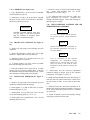
1-8. OIL SUPPLY AND MEASUREMENT.
1-10. OIL CONSUMPTION.
1-9. The capacity of the oil sump is 12 U.S. quarts.
The oil filler cap is attached over the oil filler neck
on top of the left crankcase. The oil sump is
equipped with an oil level gauge notched and
stamped with numerals representing quarts.
1-11. When operated on a rigid test stand at cruise
power settings and operating within specified limits
oil consumption shall not exceed 1 quart per hour
and one –half.
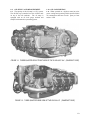
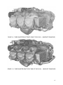
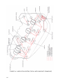
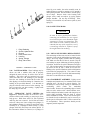
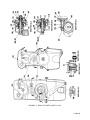
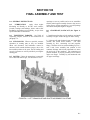
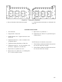
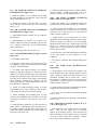
FIGURE 1-1. THREE-QUARTER RIGHT FRONT VIEW OF THE IO-520-A,E,F & K. (SANDCAST CASE)
FIGURE 1-2. THREE-QUARTER REAR VIEW OF THE IO-520-A & F. (SANDCAST CASE)
1-3
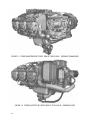
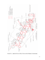
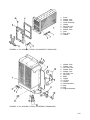
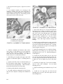
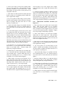
FIGURE 1-3. THREE-QUARTER RIGHT FRONT VIEW OF THE IO-520-B. (PERMOLD CRANKCASE)
FIGURE 1-4. THREE-QUARTER LEFT REAR VIEW OF THE IO-520-B. (PERMOLD CASE)
1-4
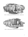
FIGURE 1-5. THREE-QUARTER RIGHT FRONT VIEW OF THE IO-520-C. (PERMOLD CASE)
FIGURE 1-6. THREE-QUARTER LEFT REAR VIEW OF THE IO-520-C. (PERMOLD CASE)
1-5
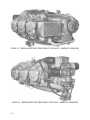
FIGURE 1-7. THREE-QUARTER RIGHT FRONT VIEW OF THE IO-520-D. (SANDCAST CRANKCASE)
FIGURE 1-8. THREE-QUARTER LEFT REAR VIEW OF THE IO-520-D. (SANDCAST CRANKCASE)
1-6
FIGURE 1-9. THREE-QUARTER RIGHT FRONT VIEW OF THE IO-520-J. (SANDCAST CRANKCASE)
FIGURE 1-10. THREE-QUARTER RIGHT FRONT VIEW OF THE IO-520-L. (SANDCAST CRANKCASE)
1-7
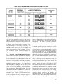
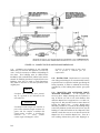
FIGURE 1-11. INSTALLATION DRAWING FOR THE IO-520-A,D,E,J,K & L.
FIGURE 1-12. INSTALLATION DRAWING FOR THE IO-520-B.
1-8
FIGURE 1-13. INSTALLATION DRAWING FOR THE IO-520-C.
1-9/1-10
Intentionally Left Blank
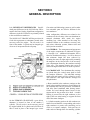
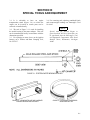
SECTION II
GENERAL DESCRIPTION
2-1. SIGNIFICANT DIFFERENCES. Specific
detail parts differences in the IO-520 Series will be
noted in the Parts Catalog. Significant configuration
differences in the IO-520 Series are primarily related
to the two different crankcases.
The SAND CAST CRANKCASE has provision for
a belt driven generator (or alternator) located at the
accessory end of the engine. The oil cooler is in
front of the number 5 cylinder and an integral type
oil screen is incorporated in the oil pump.
Gear trains and lubricating systems as well as other
less noticeable parts are likewise different in the
two crankcases.
Other configuration differences not related to the
crankcase are the oil sump, either cast aluminum or
stamped aluminum sheet metal; the engine
mounting legs, either attached to the sump, the
crankcase bottom or the crankcase accessory end;
and various induction systems, balance tubes and
fuel injection assemblies.
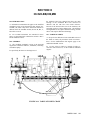
2-2. GENERAL. The arrangement and appearance
of the engine components are indicated in Figures
1-1 through 1-10. Additional information will be
found in installation drawings. It will be observed
that minimum length has been achieved by
mounting the starter on right angle and by mounting
the magnetos in the forward side of the accessory
gear compartment formed by the crankcase castings
at the rear. The magneto location also serves to
shorten the high tension cables as much as possible.
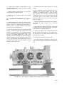
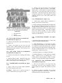
2-3. CRANKCASE. Two aluminum alloy castings
are joined along the vertical center plane to form
the complete crankcase. The individual castings
(with studs and inserts) will be referred to as the
"left crankcase" and "right crankcase" through- out
this publication.
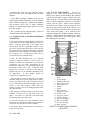
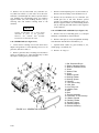
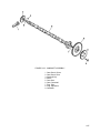
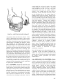
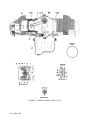
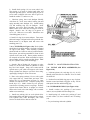
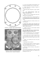
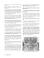
FIGURE 2-1. CROSS-SECTION OF STARTER DRIVE.
On the PERMOLD CRANKCASE a gear driven,
alternator is located in front of the number 5
cylinder. The oil cooler is at the accessory end of
the engine behind No.2 cylinder and a full flow oil
filter is used in place of the integral type screen.
a. Bosses molded in the crankcase castings are line
bored in the assembled castings to form bearings for
the camshaft and seats for precision, steel-backed,
lead alloy lined crankshaft main bearing inserts.
Guides are bored through lateral bosses for the
tappets and for the governor drive shaft. A needle
bearing is pressed into the right crankcase, to the
right of the rear main bearing, to support the front
end of the starter shaftgear.
b. Cylinder mounting pads on the left crankcase are
farther forward than the corresponding pads on the
right crankcase to permit each connecting rod to
work on a separate crankpin. Each pad has six
studs and two through bolts for attaching cylinder
2-1
base flanges. The governor mount pad is located at
the lower front corner. On the right permold
crankcase an alternator pad is located at the front.
c. The crankcase interior is ventilated by a breather
consisting of a tube and baffles assembly with a
side extension for hose attachment. The breather
assembly is pressed into the upper left crankcase.
2-4. CRANKSHAFT. The six throw, steel alloy
forging is machined allover except for some
portions of the crankcheeks. The main bearing
journals and crankpins are nitrided after grinding.
A flange is formed at the front for attaching a
propeller. An oil transfer collar, encompassing the
crankshaft between the front and rear halves of the
main thrust bearing, transfers the governor
controlled oil from the crankcase passage to the
crankshaft interior. Side blades projecting from the
crankcheeks 1 and 2, 3 and 4 are machined for the
installation of one 4th, one 5th and two 6th order
counterweights. IO-520-BA crankshafts use three
sixth order counterweights and one fourth order
counterweight. Oscillation of the counterweights
on their pins dampen crankshaft torsional vibration.
a. The crankshaft gear is heated prior to installation
to obtain a shrink fit. The gear is driven by a dowel
of uniform diameter. A cluster gear, typical of
permold engines, provides for direct drive of the
fuel pump.
b. The accessory drive gear, typical with the
permold crankcase, is heated and shrunk onto a
flange just behind the oil transfer collar at the front
of the crankshaft, and retained by four bolts.
c. A rubber oil seal, which is stretched over the
crankshaft flange and a split retainer ring are seated
between crankcase castings in front shaft exit, and
are sealed to the crankshaft by a helical spring
inside the seal's cavity.
2-5. CONNECTING RODS. The "I" beam type
connecting rods have split bronze piston pin
bushings and two identical precision inserts (of the
same type as the main bearings) at the crankpin end.
Weight variation of rods in anyone pair is limited to
1/2 ounce in opposite bays.
2-6. CAMSHAFT.
A steel alloy forging is
machined on four journals, nine cam lobes and the
gear mount flange at the rear end. The lobes and
journals are hardened and ground. A groove around
the front journal passes engine oil from the right
2-2
JANUARY 1985
crankcase cross passage to the left case passage.
The camshaft gear is attached by four unequally
spaced bolts to locate its timing mark in relation to
the cam lobes. On the sandcast crankcase, a cluster
gear is bolted with the camshaft gear and drives the
fuel pump gear.
2-7. PISTONS.
Pistons are aluminum alloy
forgings. The skirts are solid and have cylindrical
relief cuts at the bottom to clear the crankshaft
counterweights. Pistons have three grooves above
the pin hole and one groove below. Compression
rings arc installed in the top, second and the groove
below the pin hole. A center grooved and slotted
oil ring is installed in the third groove, which has
six oil drain holes to the interior. Weights are
limited to 1/2 ounce in opposite bays. Piston pins
are full floating ground steel rubes with
permanently forged-in aluminum end plugs.
2-8. TAPPETS. The barrel type hydraulic tappets
may be removed and replaced without complete
disassembly of the engine as described in Section
IV. The construction and operation of the tappets
are described in paragraph 2-15, figure 2-6.
2-9. CYLINDERS.
The externally finned
aluminum alloy head castings are heated and valve
seat inserts installed before the head is screwed and
shrunk onto an externally finned steel alloy barrel to
make the permanent head and barrel assembly.
Valve guides are pressed into the cold cylinder
assembly and reamed to slightly different
diameters. Special 18 mm helical coil thread inserts
are installed in upper and lower spark plug holes.
Smaller helical coils are installed in exhaust
manifold attaching stud holes. Both intake and
exhaust ports are on the bottom of the head when
the cylinder is installed. Exhaust valve faces are
Stellite No.6 and stem tips are hardened. Valve
stems are solid. Outer retainers of the two
concentric springs surrounding each valve are
locked to the stems by tapered, semi-circular keys
which engage grooves around the stems. Rotocaps
are installed on exhaust valves only. The rotating
action of this type retainer helps to prevent burning
and eroding of the valve and valve seat. Inner
spring retainers are pressed steel. Valve rocker
covers are aluminum alloy castings. Rocker shafts
are ground steel tubes with a hole drilled in one end
at a 90 degree angle to the longitudinal axis. The
two inside rocker shaft bosses are drilled and tapped
for the 5/16 inch rocker shaft retaining screws.
Valve rockers are steel forgings with hardened
sockets and rocker faces and pressed-in bronze
bearings.
They are drilled -for lubrication.
Pushrods are constructed of steel tubes and pressedin, hardened, forged steel ball ends, which are
center drilled for oil passages. The pushrod
housings are beaded steel tubes. The bead at the
cylinder end retains a packing ring between two
washers. The bead at the crankcase end retains a
heavy spring, washer, packing ring and second
washer.
2-10. FUNCTIONAL SYSTEMS.
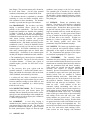
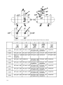
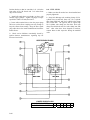
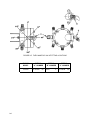
2-11. GEAR TRAIN- SANDCAST CRANKCASE (See Figure 2-2). When starting the engine,
torque is transmitted from the starter (16) through
adapter components (17 through 22) to crankshaft
gear (1). As wormwheel (20) is turned, spring
mounted on its hub is tightened to grip knurled
drum of shaftgear (22). This design eliminates
wear and stress encountered in direct drive starter
systems. After engine is started, spring returns to
its normal position, thus disengaging starter. The
shaftgear (22) is now used to transmit torque from
the crankshaft gear to the generator drive pulley
(16, Figure 4-16).
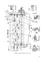
a. Torque from the crankshaft (2) is transmitted by
the crankshaft gear (1) directly to the idler gear (12)
and camshaft gear (3).
b. The idler gear, rotating in a counterclockwise
direction, drives magneto drive gears (14 and 15).
Optional accessories mounted on crankcase upper
rear are driven by internal splines of magneto drive
gears.
c. The fuel pump drive gear is driven by the
camshaft cluster gear. The splined end of the oil
pump and tachometer drive gear (8) mates with
internal splines of the camshaft gear and transmits
torque to the oil pump driven gear (9) and the
tachometer drive gear (10). The governor drive
bevel gear (6) on the front of the camshaft drives
the governor driven bevel gear (7).
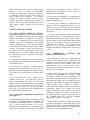
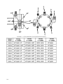
2-12. GEAR TRAIN -PERMOLD CRANKCASE
(See Figure 2-3).
a. When starting engine, torque is transmitted from
the starter (15) through adapter components (16
through 20) to crankshaft gear (1). As worm-wheel
(19) is turned, spring mounted on its hub is
tightened to grip knurled drum of shaftgear (20).
After engine is started, spring returns to its normal
position, thus disengaging starter.
Torque is
transmitted to the alternator by a face gear (23)
mounted on the crankshaft.
b. Torque from the crankshaft (2) is transmitted by
the crankshaft gear (1) directly to the idler gear (12)
and the camshaft gear (3).
c. The idler gear, rotating in a counterclockwise
direction, drives the magneto drive gears (13, 14).
Optional accessories mounted on the crankcase
upper rear are driven by internal splines of magneto
drive gears.
d. The fuel pump coupling is driven directly from
the crankshaft gear (1). The splined end of the oil
pump and tachometer drive gear (8) mates with the
internal splines of the camshaft gear and transmits
torque to the oil pump driven gear (9) and the
tachometer drive gear (11). The governor drive
bevel gear (6) is keyed to the camshaft (4) and
meshes with and drives the governor driven bevel
gear (7).
2-13.
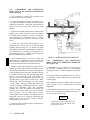
LUBRICATION
SYSTEM
SANDCAST CRANKCASE.
FOR
a. The engine driven, gear type oil pump draws oil
from the sump through the oil suction tube and
crankcase oil passage. From the gear chamber oil is
directed to the oil filter chamber and to the
tachometer drive gear. A filter by-pass valve is
incorporated in the pump housing in the event that
the filter becomes clogged.
b. After leaving the pump oil is directed through
passages to the right crankcase oil gallery. Right
side lifters, guides and valve mechanisms are
lubricated by passages leading off this gallery. An
oil temperature control valve is located at the front
end of the right gallery to regulate oil temperature
within specific limits.
When oil reaches a
temperature high enough to require cooling, the oil
temperature control valve expands and blocks
passage, directing oil to the oil cooler. From the oil
temperature control valve cavity oil is directed to
the camshaft passage. A groove around the front of
the camshaft directs oil to the front camshaft
bearing and left crankcase oil gallery .
c. Lubricating oil is directed to the governor drive
gear and the propeller governor through pass- ages
off the left main gallery. Oil is channeled through a
discharge port to the crankshaft oil transfer collar,
which directs it to the crankshaft interior.
2-3
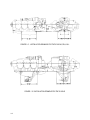
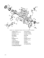
FIGURE 2-2. GEAR TRAIN DIAGRAM (TYPICAL WITH SANDCAST CRANKCASE).
1.
2.
3.
4.
5.
6.
7.
8.
9.
10.
11.
12.
13.
14.
15.
16.
17.
18.
19.
20.
21.
22.
23.
2-4
Crankshaft gear.........................................................
Crankshaft.................................................................
Camshaft cluster gear...............................................
Camshaft...................................................................
Hydraulic tappet ........................................................
Governor drive bevel gear ........................................
Governor driven bevel gear ......................................
Oil pump and tachometer drive shaftgear.................
Oil pump driven gear.................................................
Tachometer drive bevel gear ....................................
Tachometer shaftgear...............................................
Idler gear assembly...................................................
Idler gear support pin ................................................
Left magneto drive gear ............................................
Right magneto drive gear..........................................
Starter,
.............................................................
Worm drive shaft .......................................................
Worm shaft spring .....................................................
Starter worm gear .....................................................
Starter worm wheel ...................................................
Clutch spring .............................................................
Starter shaftgear .......................................................
Fuel pump drive gear ................................................
1:1
1
1:0.5
1:0.5
-1:0.5
1:1
1:0.5
1:0.5
1:0.5
1:0.5
1:0.652
-1:1.5
1:1.5
32:1
32:1
-32:1
2:1
2:1
1:2
1:1
FIGURE 2-3. GEAR TRAIN DIAGRAM (TYPICAL WITH PERMOLD CRANKCASE).
1.
2.
3.
4.
5.
6.
7.
8.
9.
10.
11.
12.
13.
14.
15.
16.
17.
18.
19.
20.
21.
22.
23.
Crankshaft gear.........................................................
Crankshaft.................................................................
Camshaft gear...........................................................
Camshaft...................................................................
Hydraulic tappet ........................................................
Governor drive bevel gear ........................................
Governor driven bevel gear ......................................
Oil pump and tachometer drive shaftgear.................
Oil pump driven gear.................................................
Tachometer drive bevel gear ....................................
Tachometer drive bevel gearshaft ............................
Idler gear assembly...................................................
Right magneto drive gear..........................................
Left magneto drive gear ............................................
Starter .......................................................................
Starter coupling .........................................................
Worm drive shaft .......................................................
Starter worm gear .....................................................
Starter worm wheel ...................................................
Starter shaftgear .......................................................
Alternator...................................................................
Alternator driven gear ...............................................
Alternator drive gear .................................................
1:1
1
1:0.5
1:0.5
-1:0.5
1:1
1:0.5
1:0.5
1:0.5
1:0.5
1:0.652
1:1.5
1:1.5
48:1
-48:1
48:1
2:1
1:3
3:1
3:2
1:1
2-5
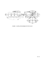
FIGURE 2-4. LUBRICATION SYSTEM (TYPICAL WITH SANDCAST CRANKCASE).
2-6
FIGURE 2-5. LUBRICATION SYSTEM (TYPICAL WITH PERMOLD CRANKCASE).
2-7
d. Passageways from the left crankcase gallery
direct oil to the front, intermediate and rear main
bearings.
e. Four drilled passages radiating from the rear
main bearing conduct lubricating oil to the adapter
ports of the fuel pump drive, right and left magneto
and accessory drives and to starter shaftgear
bearing. An intersecting passage directs oil to the
idler gear support.
f. Oil is returned to the sump through a system of
oil transfer tubes and drain holes.
2-14. LUBRICATION SYSTEM FOR PERMOLD
CRANKCASE.
2-15. VALVE MECHANISM.
Oil fed to
hydraulic valve lifters, under pressure from the
hollow cam- shaft is divided between the overhead
system, the lifter guide surfaces and the reservoirs
inside the lifters. The oil which reaches the pushrod
ends is forced through the pushrods to the drilled
rockers and the groove between their bushings.
Each intake valve rocker directs a portion of its oil
through a squirt nozzle towards the exhaust valve
stem. The oil spray from the rockers lubricates the
valve stems and springs. Oil is returned to the
crankcase through the pushrod housings which are
sealed to cylinder heads and crankcase by rubber
packings. Drain holes in valve lifter guides direct
the returning oil to the sump.
a. Oil is drawn from the sump through the suction tube
to the intake side of the engine driven, gear type, oil
pump. From the outlet side of the pump, oil is
directed to the full flow, replaceable oil filter. A bypass valve is incorporated in the filter in the event that
the element becomes clogged. Lubrication reaches the
tachometer drive gears through oil passages drilled in
the oil pump cover. An oil pressure relief valve is
incorporated in the oil pump housing.
b. From the filter discharge port, oil is directed
through a crankcase passage to the oil cooler. In
addition to facilities for temperature and oil pressure
connections, the oil cooler incorporates an oil
temperature control valve. Oil passing through the oil
temperature control valve cavity is directed either
through the oil cooler or directly to the crankcase
passage to the rear of the camshaft, depending on the
oil temperature.
In this manner, engine oil
temperature is maintained at 170°F.
c. Oil entering the engine is directed to the hollow
camshaft, which serves as the engine main oil gallery.
Grooves and drilled holes in the camshaft are located
so as to afford proper lubrication through a system of
orifices to the main bearings, lifters, idler gear
bushing, accessory drive gear bushings and the starter
drive gear bearing.
d. Oil leaving the camshaft interior at the front of the
crankcase is directed to the left main crank- case
gallery. From there it is directed to the main thrust
bearing and the governor drive gear.
e. From the governor drive gear lubricating oil is
directed to the crankshaft oil transfer collar, which in
turn directs oil to the interior of the crankshaft.
f. Oil transfer tubes and drain holes are provided to
return oil to the sump.
2-8
MAY 1980
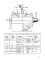
1.
2.
3.
4.
5.
6.
7.
8.
9.
10.
11.
12.
13.
14.
15.
16.
Body
Spring, plunger
Housing, check valve
Spring, check valve
Plate, check valve
Plunger
Socket
Ring, retaining
Oil groove, exterior
Oil inlet, body
Oil groove, interior
Oil inlet, plunger
Oil reservoir plunger
Hole, oil discharge
Oil reservoir, body
Hole, oil outlet
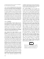
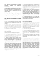
FIGURE 2-6. CUT-AWAY VIEW OF HYDRAULIC
VALVE LIFTER.
2-16. The barrel type hydraulic lifter (See Figure 26) consists of a steel body (1), an expanding spring
(2), and a check valve assembly (3, 4 and 5), a
plunger (6), a socket (7) for pushrod end, and a
retaining ring (8). A groove (9), around outside of
body picks up oil from crankcase supply hole only
when lifter is near outer end of its stroke so engine
pressure will not "pump up" plunger and hold the
valve off its seat. From the exterior groove oil is
directed to interior body groove (11) through hole
(10) and from the interior groove through the hole
(12) to the reservoir (13). Oil is withheld from
reservoir (15) by check valve plate (5) which is
supported by spring (4) of housing (3). The check
valve is opened by outward motion of the plunger
under pressure of the expanding spring whenever a
clearance occurs in the valve train. Thus the body
reservoir is kept full of oil which transmits lifting
force from body of plunger. The plunger and socket are fitted to the body selectively to permit a
calibrated leakage so the lifter will readjust its
effective length after each cycle, while cylinder
valve is closed, to return "lash" in valve train to
zero.
2-17. INDUCTION SYSTEM. The air induction
system used on the IO-520 Series Engines consists
of intake tubes, a balance tube, connecting hoses,
clamp assemblies and a combination air throttle and
fuel metering control. The air throttle assembly
may be located at the rear of the engine supported
by brackets or below the oil sump supported by an
inverted manifold assembly or bolted to a cast oil
sump. The systems are provided with a drain valve
at the lowest point in the manifold assembly to
remove any fuel that may collect there.
The throttle assembly is connected to the elbows at
the rear cylinder intake tubes by connector hoses
and clamps. This assembly is then connected to the
center intake tubes and the center to the front intake
tubes in the same manner. Each intake tube is
attached to the cylinder by a welded flange and four
bolts and is sealed by a gasket. The front cylinder
intake tubes are connected by a balance tube
assembly. The balance tube incorporates a boss and
is supported by a bracket attached to the front of the
oil sump.
2-9/2-10
Intentionally Left Blank
SECTION III
SPECIAL TOOLS AND EQUIPMENT
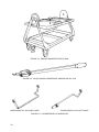
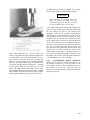
3-1. It is advisable to have an engine
transportation stand (Figure 3-4) on which the
engine can be inverted so certain parts can be
removed or installed easily.
3-2. The tool in Figure 3-1 is used for installing
the needle bearing in the starter adapter. This tool
can be manufactured locally in accordance with the
dimensions specified.
3-3. For replacing an outer sleeve on the ignition
harness, use a Thomas and Betts Crimping Tool,
No. WT-217.
3-4. For removing and replacing crankshaft blade
and counterweight bushings use Borrough’s Tool
No. 4965.
NOTE
Special tools for Aircraft Engine in
general and the IO-520 in particular can
be purchased from the Borrough’s Tool
and Equipment Corporation 2429 North
Burdick Street, Kalamazoo, Michigan
49007.
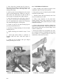
FIGURE 3-1. STARTER ADAPTER BEARING INSTALLER
FIGURE 3-2. CRANKSHAFT BLADE AND DAMPENER
BUSHING REMOVER AND REPLACER
FIGURE 3-3. PISTON RING COMPRESSOR,
BORROUGHS NO. 5201
3-1
FIGURE 3-4. ENGINE TRANSPORTATION STAND
FIGURE 3-5. VALVE SPRING COMPRESSOR, BORROUGHS NO. 5202
BORROUGHS NO. 5204 RIGHT HAND
BORROUGHS NO. 5203 LEFT HAND
FIGURE 3-6. CYLINDER BASE NUT WRENCHES
3-2
SECTION IV
DISASSEMBLY
4-1. GENERAL. .
4-2. AIRCRAFT PARTS AND ACCESSORIES.
4-3. Instructions in this section are based on the
assumption that all parts attached by the aircraft
manufacturer, except optional pumps, have been
removed.
4-4. Accessories supplied by the engine manufacturer
may be serviced according to instructions supplied by
the applicable accessory manufacturer.
4-5. EXTENT OF DISASSEMBLY. Line drawings
reproduced in this section are identical to those used
in the parts catalog, except for order of index numbers
assigned to components. Index numbers herein
indicate the order of disassembly. In many instances
the location of components and attaching parts in the
illustration will be sufficient to enable personnel to
accomplish disassembly operations. In such instances
such disassembly is to be accomplished, even though
there are no printed instructions to that effect,
excepting those parts which need to be removed only
for replacement. Such parts include studs, bushings,
and other tight fit inserts. The identity of these will be
obvious.
4-6. PARTS TO BE DISCARDED. Discard all
shakeproof washers, lockwires, tab washers, rubber
seal rings, oil seals, gaskets, cotter pins, hose
connectors and magneto coupling (rubber) bushings in
such manner that they will not be used again
inadvertently. Care should be taken in removing
gaskets from aluminum parts by scraping. Such
removal should be delayed until the part is to be
cleaned.
engine stand with a tilting bed. See the installation
drawings for necessary dimensions for mounting
engine on stand.
4-8. PRELIMINARY CLEANING. Spray, or apply
with a brush, a solvent used for general cleaning of
engine parts. Remove caked dirt on bolt heads and
nuts especially. At the same time the oil sump drain
plugs should be removed to drain any remaining oil.
CAUTION
Do not use a caustic or even mild
alkaline cleaning solution for external
pre-cleaning, as these solutions will also
remove the "alodized" finish of certain
aluminum parts.
4-9. DISMANTLING.
4-10. IGNITION SYSTEM.
a. Disconnect cables from spark plugs.
b. Detach ignition cable retaining clamps from fuel
discharge brackets.
c. Detach clip from cable bracket on top of crankcase.
Disengage band clamps.
d. Detach high tension cable outlet plates from
magnetos and withdraw them to free cable assemblies.
e. Remove two attaching nuts, lockwashers and
holding washers from each magneto. Withdraw
magnetos forward from the crankcase.
4-7. DISASSEMBLY STAND. For greatest ease of
disassembly, this engine should be mounted on an
4-1
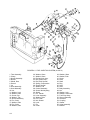
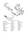
FIGURE 4-1. FUEL INJECTION SYSTEM (IO-520-A,E,F,J,K & L)
1. Clamp, Fuel Discharge Tube
2. Tube Assembly
3. Nozzle Assembly
4. Nozzle
5. Shield, Dust
6. Screen
7. Jet
8. Hose Assembly
9. Hose Assembly
10. Hose Assembly
11. Nut, Plain, Hex
12. Washer, Lock
13. Washer, Plain
14. Shroud Assembly
15. Pin, Cotter
16. Washer, Plain
17. Washer, Wave
18. Spring, Throttle
19. Nut, Elastic Stop
20. Rod End, Special
4-2
21. Spring, Compression
22. Rod and Link Assembly
23. Screw, Special
24. Washer, Tab
25. Control Assy., Complete
26. Screw, Idle Adjusting
27. Spring, Idle Adjusting
28. Pin, Tubular
29. Lever, Throttle Shaft
30. Washer, Wave
31. Washer, Plain
32. Pin, Tubular
33. Lever
34. Washer, Plain
35. Screw
36. Plate, Air Throttle
37. Shaft
38. Plug, Pipe
39. Stud
40. Body Assembly, Air
41. Nut, Plain, Hex
42. Washer, Lock
43. Washer, Plain
44. Fuel Pump Assembly
45. Spring
46. Screw
47. Nut, Tinnerman
48. Grommet
49. Shroud Assembly
50. Gasket
51. Coupling Drive
52. Gear Assy., Fuel Pump
53. Gear
54. Plug
55. Valve Assy., Fuel Manifold
56. Screw
57. Washer, Lock
58. Bracket
59. Fuel Manifold Valve
60. Bracket, Discharge Tubes
FIGURE 4-2. FUEL INJECTION SYSTEM (IO-520-B)
1. Clamp
2. Tube Assembly
3. Nozzle Assembly
4. Jet
5. Screen
6. Shield, Dust
7. Nozzle
8. Hose Assembly
9. Hose Assembly
10. Clamp
11. Clamp
12. Bracket
13. Nut, Plain, Hex
14. Washer, Lock
15. Washer, Plain
16. Bolt
17. Bolt
18. Washer, Plain
19. Pin, Cotter
20. Washer, Plain
21. Washer, Wave
22. Nut, Elastic Stop
23. Rod End, Special
24. Spring, Compression
25. Rod and Link Assembly
26. Nut, Plain, Hex
27. Washer, Lock
28. Washer, Plain
29. Screw
30. Washer, Tab
31. Shroud, Metering Shaft
32. Control Assembly
33. Pin, Tubular
34. Collar
35. Washer, Wave
36. Washer, Plain
37. Screw
38. Plate Air Throttle
39. Screw, Idle Adjusting
40. Spring
41. Pin, Cotter
42. Nut, Plain, Hex
43. Lever, Throttle Control
44. Shaft, Air Throttle
45. Body Assembly, Air
46. Nut, Plain, Hex
47. Washer, Lock
48. Washer, Hold Down
49. Fuel Pump Assembly
50. Shroud Assembly
51. Coupling
52. Gasket
53. Fuel Manifold Valve Assy.
54. Screw
55. Washer, Lock
56. Bracket, Discharge Tubes
57. Grommet
4-3
FIGURE 4-3. FUEL INJECTION SYSTEM (IO-520-C)
1. Tube Assembly
2. Clamp
3. Nozzle Assembly
4. Nozzle
5. Shield, Dust
6. Screen
7. Jet
8. Hose Assembly
9. Hose Assembly
10. Nut
11. Washer, Lock
12. Washer, Plain
13. Screw, Cap
14. Washer, Tab
15. Shroud Assembly
16. Pin, Cotter
17. Washer, Plain
18. Pin, Cotter
19. Washer, Plain
4-4
20. Washer, Wave
21. Washer, Wave
22. Rod and Link Assy.
23. Nut, Elastic Stop
24. Rod, End, Special
25. Spring, Compression
26. Screw, Special
27. Washer, Tab
28. Control Assembly
29. Screw, Idle Adjusting
30. Spring
31. Pin, Tubular
32. Lever Assembly
33. Washer, Plain
34. Pin, Cotter
35. Nut, Slotted
36. Lever
37. Pin
38. Collar
39. Washer, Wave
40. Washer, Plain
41. Screw
42. Plate
43. Shaft
44. Plug
45. Stud
46. Stud
47. Body Assembly
48. Nut
49. Washer, Lock
50. Washer, Hold Down
51. Fuel Pump Assy.
52. Shroud Assembly
53. Grommet
54. Coupling
55. Gasket
56. Valve Assembly
57. Bracket
FIGURE 4-4. FUEL INJECTION SYSTEM (IO-520-D)
1. Tube Assembly
2. Clamp
3. Nozzle Assembly
4. Nozzle
5. Shield, Dust
6. Screen
7. Jet
8. Hose Assembly
9. Hose Assembly
10. Hose Assembly
11. Body Assembly
12. Pin, Cotter
13. Pin, Cotter
14. Washer, Wave
15. Rod and Link Assy.
16. Nut, Elastic Stop
17. Rod, End, Special
18. Spring, Compression
19. Nut, Plain, Hex
20. Washer, Lock
21. Washer, Plain
22. Shroud
23. Bolt, Special
24. Washer, Tab
25. Control Assembly
26. Pin
27. Lever
28. Washer, Wave
29. Washer, Plain
30. Bushing
31. Pin
32. Screw
33. Spring
34. Lever
35. Washer
36. Screw
37. Plate
38. Shaft
39. Pin
40. Screw
41. Nut
42. Screw
43. Spring
44. Shroud Assy.
45. Grommet
46. Nut
47. Washer, Lock
48. Washer, Plain
49. Fuel Pump Assy.
50. Gasket
51. Coupling
52. Gear
53. Plug
54. Valve Assembly
55. Bracket
4-5
4-11. FUEL INJECTION SYSTEM (See Figures
4-1, 4-2 and 4-3).
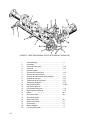
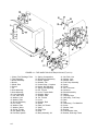
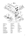
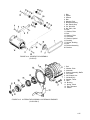
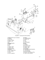
4-12. MAGNETO AND ACCESSORY DRIVES (See
Figure 4-5).
a. Use the following basic procedure to disassemble the
fuel injection system on the IO-520 Series.
a.
Remove two sets of attaching parts (1, 2, 3) and six
sets of attaching parts (4, 5,6) and remove adapter
assembly (7) and related parts as a unit.
b.
Remove gear assembly (18), magneto drive coupling
bushings (21) and retainer (22).
c.
Remove attaching parts (8, 9, 10) and lift cover (11)
and gasket (12). Remove oil seal (14) from adapter
(17).
Disconnect:
1.
Fuel discharge tubes and nozzles.
(a) Tubes at fuel manifold valve.
(b) Tube at nozzles.
(c) Clips at tube bracket.
(d) Nozzles at engine.
NOTE
Remove fuel injection connection
fittings from fuel injection components
only if necessary for replacement.
2.
Fuel Hoses.
(a) Fuel pump to metering unit.
(1) Fuel hose to metering unit.
(2) Fuel pump return.
(b) Metering unit to fuel manifold valve.
3.
Throttle body and metering unit from engine.
(a) Remove clamps etc. from intake manifold.
(b) Remove miscellaneous attaching parts.
4.
Metering unit from throttle body.
(a) Remove linkage.
(b) Remove miscellaneous attaching parts and
shroud.
(c) Disassembly throttle body.
(1) Levers.
(2) Butterfly.
5.
Fuel pump from engine.
(a) Shroud.
(b) Attaching parts.
(c) Coupling, gear and gasket.
6.
Fuel manifold valve and bracket from engine.
(a) Attaching parts.
(b) Valve from bracket.
NOTE
Further disassembly of fuel injection
system components is not advised unless
proper test equipment is available.
For further information see Teledyne
Continental Fuel Injection System
Manual, Form X-30091.
4-6
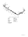
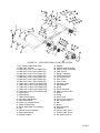
FIGURE 4-5. MAGNETO & ACCESSORY DRIVES.
1. Nut, Plain, Hex
2. Washer, Lock
3. Washer, Plain
4. Nut, Plain, Hex
5. Washer, Lock
6. Washer, Plain
7. Adapter Assembly
8. Nut, Plain, Hex
9. Washer, Lock
10. Washer, Plain
11. Cover, Accy. Drive
12. Gasket
13. Gasket
14. Seal, Oil
15. Bushing, Adapter
16. Stud
17. Adapter
18. Gear Assembly
19. Sleeve
20. Gear, Drive
21. Bushing
22. Retainer
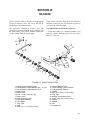
4-13. INDUCTION SYSTEM.
a.
IO-520-A, B, C, F,J, K, L (See Figure 4-6).
(1.) Loosen hose clamps (1) or clamp assemblies (2)
on hoses (3) or (4) and remove elbows (5, 6) or elbow
assembly (7).
(2.) Remove attaching parts (8, 9) loosen hose
clamps (II, 12) and remove balance tube (13) and
bracket (10).
(3.) Loosen hose clamps (14) from hoses (15) and
remove attaching parts (16, 17, 18). Remove intake
manifold tubes (19,20) and gasket (21).
(4.) BRACKETS. remove attaching parts (23 through
35) to separate brackets (36, 37, 38), bushing (39),
sleeve (40) and housing (41).
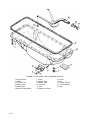
4-14. OIL SUMP IO-520-A, D, E, F, J, K AND L
(See Figure 4-9).
a. Drain plug (1) and gasket (2) should have been
removed when engine was mounted on stand. Remove
attaching parts (3, 4, 5) and lift sump from engine.
b. Remove screws (8, 9) and washers (10) and lift
off suction tube assembly (11).
c. Remove screw (13), washer (14), acorn nut (15)
and gasket (16) and withdraw oil suction tube (17).
4-15. OIL SUMP IO-520-B (See Figure 4-10).
a. Drain plug (1) and gasket (2) should have been
removed when engine was mounted on stand.
b. Remove attaching parts (3, 4, 5) and lift off
mounting legs (6).
(5.) BRACKETS. Remove attaching parts (42
through 47) to separate brackets (48, 49, 50, 51),
bushing (52, 53), sleeves (54, 55) and housing (41).
c. Remove attaching parts (7, 8, 9) and lift off sump
(10).
b.
d. Remove screw (13), nut (14), gasket (15) and
withdraw oil suction tube (16).
IO-52O-D (See Figure 4-7).
(1.) Loosen hose clamps (1) on hoses (2) and remove elbows (3, 4).
(2.) Remove attaching parts (5, 6), loosen hose hose
clamps (8, 9) and remove balance tube (10) and
bracket (7).
(3.) Loosen hose clamps (11) from hoses (2) and
remove attaching parts (12, 13, 14). Remove in- take
manifold tubes (15,16) and gasket (17).
(4.) Remove attaching parts (19, 20) and sepa- rate
throttle assembly (21) from engine.
c.
IO-520-E (See Figure 4-8).
(1.) Loosen hose clamps (1) on hoses (2) and remove elbows (3,4).
4-16. OIL COOLER (See Figure 4-11).
a. Remove attaching parts (1, 2, 3) and separate
cooler (4) from adapter.
b. Remove attaching parts (6, 7, 8) and pull adapter
(9) from crankcase.
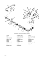
4-17. OIL COOLER (See Figure 4-12).
a. Remove four sets of attaching parts (1, 2, 3) and
one set of attaching parts (4, 5,6) and remove oil
cooler.
b. Remove baffle (15) and oil temperature control
valve (12).
4-18. GENERATOR (See Figure 4-13).
(2.) Remove attaching parts (5, 6), loosen hose
clamps (8, 9) and remove balance tube (10) and
bracket (7).
a. Loosen sheave retaining nut on both starter drive
adapter and generator and adjusting arm screw. Tilt
generator and remove bolt (1).
(3.) Loosen hose clamps (11) from hoses (2) and
remove attaching parts (12, 13, 14). Remove in- take
manifold tubes (15,16) and gasket (17).
b. Remove generator sheave retaining nut and remove spacer (2) and sheave (3). Tape woodruff key to
shaft and replace retaining nut to protect threads.
(4.) Remove attaching parts (18 through 27) and
remove throttle assembly (28).
c. Remove bracket adjusting screw (4) and washer
(5). Remove bracket retaining screw (6), washers (7),
bushings (8), and sleeve (9) to remove bracket (10).
(5.) Remove attaching parts (29 through 32) and
remove brackets (33, 34, 35).
4-7
FIGURE 4-6. INDUCTION SYSTEM. (A,B,C,F,J,K & L)
1. Clamp, Hose
2. Clamp Assembly
3. Hose, Intake Manifold
4. Hose
5. Tube Assy., Elbow, 2-4-6 Side
6. Tube Assy., Elbow, 1-3-5 Side
7. Manifold Assembly
8. Bolt
9. Washer, Lock
10. Bracket
11. Clamp
12. Clamp
13. Tube Assembly, Balance
14. Clamp, Hose
15. Hose
16. Screw
17. Washer, Lock
18. Washer, Plain
19. Tube Assembly
4-8
20. Tube Assembly
21. Gasket
22. Plug, Pipe
23. Screw
24. Washer, Lock
25. Nut, Plain, Hex
26. Washer, Lock
27. Screw
28. Nut, Plain, Hex
29. Washer, Lock
30. Washer, Plain
31. Nut, Self Locking
32. Bolt
33. Nut, Plain, Hex
34. Washer, Lock
35. Washer, Plain
36. Bracket
37. Bracket
38. Bracket
39. Bushing
40. Sleeve
41. Throttle Assembly, Air
42. Nut, Self-Locking
43. Bolt
44. Nut, Plain, Hex
45. Washer, Lock
46. Nut, Plain, Hex
47. Washer, Lock
48. Bracket Assembly
49. Bracket
50. Bracket
51. Bracket Assembly
52. Bushing
53. Bushing
54. Sleeve
55. Sleeve
56. Gasket
FIGURE 4-7 INDUCTION SYSTEM. (IO-520-D)
1. Clamp
2. Hose
3. Tube
4. Tube
5. Screw
6. Washer, Lock
7. Bracket
8. Clamp
9. Clamp Assembly
10. Tube Assembly
11. Clamp, Hose
12. Screw
13. Washer, Lock
14. Washer, Plain
15. Tube Assembly
16. Tube Assembly
17. Gasket
18. Plug, Pipe
19. Throttle Assy., Air
MAY 1980
4-9
FIGURE 4-8 INDUCTION SYSTEM. (IO-520-E)
1. Clamp
2. Hose
3. Tube Assembly
4. Tube Assembly
5. Bolt
6. Washer, Tab
7. Bracket
8. Clamp
9. Clamp Assembly
10. Tube Assembly
11. Clamp
12. Screw
13. Washer, Lock
4-10
14. Washer, Plain
15. Tube Assembly
16. Tube Assembly
17. Gasket
18. Nut, Hex
19. Washer, Lock
20. Nut
21. Washer, Lock
22. Screw
23. Nut
24. Washer, Lock
25. Bracket
26. Grommet
27. Sleeve
28. Throttle Assembly
29. Nut. Self-Locking
30. Bolt
31. Nut, Plain, Hex
32. Washer, Lock
33. Bracket
34. Bracket
35. Bracket Assembly
36. Bushing
37. Sleeve
38. Gasket
FIGURE 4-9 OIL SUMP (STAMPED ALUMINUM SHEET METAL IO-520-A,C,D,E,F & K)
1. Plug, Oil Drain
2. Gasket, Annular
3. Screw
4. Washer, Lock
5. Washer, Plain
6. Sump Assembly, Oil
7. Gasket, Oil sump
8. Screw
9. Screw
10. Washer, Plain
11. Tube Assembly
12. Gasket
13. Bolt.
14. Washer, Special
15. Nut
16. Gasket, Annular
17. Tube Assembly
4-11
FIGURE 4-10 OIL SUMP (CAST ALUMINUM IO-520-B)
1. Plug, Oil Drain
2. Gasket
3. Nut, Plain, Hex
4. Washer, Lock
5. Washer Plain
6. Bracket, Engine Mount
4-12
7. Screw
8. Washer, Lock
9. Washer, Plain
10. Sump, Oil
11. Felt
12. Gasket, Oil Sump
13. Screw
14. Nut
15. Gasket, Annular
16. Tube Assembly
17. Stud
1.
2.
3.
4.
5.
6.
7.
8.
9.
10.
11.
Screw
Washer, Lock
Washer, Plain
Cooler Assembly
Gasket
Nut, Plain, Hex
Washer, Lock
Washer, Plain
Plate
Plug, pipe
Gasket
1.
2.
3.
4.
5.
6.
7.
8.
9.
10.
11.
12.
13.
14.
15.
Washer, Plain
Washer, Lock
Nut, Plain, Hex
Washer, Plain
Washer, Lock
Nut, Plain, Hex
Oil Cooler
Baffle
Gasket
“O” Ring
Gasket
Valve Assembly
Plug
Plug
Support Assembly
FIGURE 4-11 OIL COOLER (TYPICAL ON SANDCAST CRANKCASE).
FIGURE 4-12 OIL COOLER (TYPICAL ON PERMOLD CRANKCASE).
4-13
d. Remove nut (13) and washer (14), and bolts (15,
16); Idler kiss bracket (17) will come off at this time.
Generator (18) should pull free. Remove special washers
(19), bushings (20), and bushing spacer (21). Remove
support bracket (22) and mounting bracket (23) by
removing nuts and washers retaining them to the
crankcase.
c.
Remove bracket adjusting screw (4) and washer (5).
Remove bracket retaining screw and bracket (6). 4
d.
Remove nut (9) and bolts (10, 12). Generator (14)
should pull free at this time. Remove special
washers (15), bushings (16) and bushing spacer (17).
Remove support bracket (19) and mounting bracket
(20) by removing nuts and washers retain- ing them
to the crankcase.
NOTE
4-20. ALTERNATOR ASSEMBLY (See Figure 4-15).
Certain specifications use a belt driven
alternator in place of the generator.
However, the removal and assembly
instructions are basically the same.
4-19. GENERATOR (See Figure 4-14).
a. Loosen sheave retaining nut on both starter drive
adapter and generator. Loosen adjusting arm screw, tilt
generator, and remove belt (1).
a. Remove four sets of attaching parts (1, 2) and pull
alternator (3) and baffle (4) from crankcase.
b. Remove cotter pin (5), nut (6) and pull hub assembly
from alternator shaft. Remove Woodruff key (7).
c. Separate thrust washer (8), gear assembly (9, 10),
clutch spring (11) and hub (12).
d.
Remove “O” ring (13).
b. Remove generator sheave retaining nut and remove
spacer (2) and sheave (3). Tape Woodruff key to shaft
and replace retaining nut to protect threads.
1. Belt, Generator Driven
2. Spacer, Generator Driven
3. Sheave, Generator Driven
4. Screw
5. Washer, Plain
6. Screw
7. Washer, Special
8. Bushing, Rubber
9. Bushing, Spacer
10. Bracket
11. Nut, Self-Locking
12. Idler, Kiss
13. Nut, Plain, Hex
14. Washer, Plain
15. Bolt
16. Bolt
17. Bracket Assembly
18. Generator, 12 Volt, 50 Amp.
19. Washer, Special
20. Bushing, Rubber
21. Bushing, Spacer
22. Bracket, Support
23. Bracket, Mounting
FIGURE 4-13. GENERATOR ASSEMBLY
4-14
1. Belt
2. Spacer
3. Sheave
4. Bolt
5. Washer, Plain
6. Bracket Assembly
7. Nut, Elastic Stop
8. Pin, Idler Kiss
9. Nut, Plain, Hex
10. Bolt
11. Washer, Plain
12. Bolt
13. Washer, Plain
14. Generator
15. Washer, Special
16. Bushing
17. Spacer, Bushing
18. Bolt
19. Bracket Assembly
20. Bracket
FIGURE 4-14. GENERATOR ASSEMBLY
(IO-520-E)
1. Bolt
2. Washer, Plain
3. Alternator
4. Support Assembly, Baffle
5. Pin, Cotter
6. Nut, Slotted, Hex
7. Woodruff Key
8. Washer, Thrust
9. Gear
10. Bushing
11. Spring, Clutch
12. Hub, Alternator
13. Gasket
FIGURE 4-15. ALTERNATOR ASSEMBLY ON PERMOLD ENGINES
(IO-520-B & C)
4-15
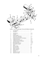
4-21. STARTER AND STARTER DRIVE ADAPTER
(See Figure 4-16).
4-22. STARTER AND STARTER
ADAPTER (See Figure 4-17).
a.
Remove two sets of attaching parts (1, 2, 3) and
pull starter from starter adapter studs. Remove "O" ring
(5).
a.
Remove attaching parts ( 1, 2) and pull 4 starter (3)
from adapter studs. Remove “O” ring (4).
b. Remove attaching parts (6 through 11) and pull
starter adapter assembly from crankcase studs. Remove
gasket (12).
c.
Clamp shaftgear (33) in shielded vise jaws and
remove nut (13), lockwasher (14) and plain washer (15).
Pull sheave (16) from shaft and remove Woodruff key
(21).
d. Remove attaching parts (17, 18, 19) and pull cover
(22) together with sleeve (24) and oil seal (25) from
shaft.
e.
Use Truarc No.3 or No. 23 pliers and remove
retaining ring (26). Remove sleeve and use arbor press to
remove oil seal. Remove gasket (23) from adapter.
f.
Support rear side of adapter (41) on blocks and tap
front end of clutch spring (29) carefully with a brass drift
or pin punch all around.
g. Use a wheel puller or arbor press to press the
shaftgear (33) from the wormwheel (32) and bearing
(30).
h. Clamp wormwheel in shielded vise and remove
retaining screw (27) and tab washer (28). Rotate the
spring until its depressed rear end lies across the upper
1/4 inch hole in the flange. Insert a 3/16 inch wide
screwdriver blade, and pry the spring end outward clear
of the drum groove. Hold it out while pulling the spring
away.
i.
Clamp adapter in shielded vise and remove
retaining ring (34) with Truarc No.5 or No. 25 pliers.
Remove bearing (37) and worm and shaft assembly.
j.
Separate worm gear (35), spring (36), Wood- ruff
key (38) and shaft (39).
k. Use arbor press to remove needle bearing (40) from
adapter (41).
4-16
DRIVE
b. Remove four sets of attaching parts (5, 6, 7) and
pull starter adapter assembly from crankcase. Remove
gasket (8).
c.
Remove three sets of attaching parts (9, 10, 11) and
detach cover (12) and “O” ring (13) from starter adapter.
d. Support adapter on wood blocks and tap clutch
spring carefully around front end with a brass drift to
remove clutch spring assembly.
e.
Remove retaining ring (14). Use arbor press to
remove shaftgear (21) from bearing (15) and worm gear
(19).
f.
Clamp worm gear in shielded vise and remove
clutch spring retaining screw (16) and tab washer (17).
Turn clutch spring (18) until its depressed rear end lies
across the 1/4 inch worm gear hub. Use a 3/16 inch
screwdriver blade to pry spring outward clear of drum
groove. Hold spring end out while pulling spring from
drum.
g. Clamp adapter in shielded vise jaws. Remove
retaining ring (22) using Truarc No.5 or No. 25 pliers.
Remove bearing (23) and worm shaft assembly.
h. Separate worm gear (24), spring (25), Woodruff
key (26), and shaft (27).
i.
Use arbor press to remove needle bearing (28) from
adapter (32).
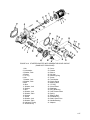
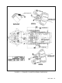
FIGURE 4-16. STARTER ADAPTER WITH GENERATOR DRIVE SHEAVE.
(SANDCAST CRANKCASE)
1. Nut
2. Lockwasher
3. Washer, Plain
4. Starter
5. “O” ring
6. Nut
7. Washer, Lock
8. Washer, Plain
9. Bolt
10. Bolt
11. Washer, Lock
12. Gasket
13. Nut
14. Washer, Lock
15. Washer, Plain
16. Sheave
17. Screw
18. Washer, Lock
19. Washer, Plain
20. Indicator, Timing
21. Woodruff Key
22. Cover
23. Gasket
24. Sleeve
25. Oil Seal
26. Retaining Ring
27. Screw
28. Tab Washer
29. Clutch Spring
30. Bearing, Ball
31. "0" Ring
32. Worm Wheel
33. Shaftgear
34. Ring, Retaining
35. Gear, Starter Worm
36. Spring
37. Bearing, Ball
38. Woodruff Key
39. Shaft, Worm Drive
40. Needle Bearing
41. Adapter
4-17
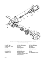
FIGURE 4-16. STARTER ADAPTER WITH GENERATOR DRIVE SHEAVE.
(SANDCAST CRANKCASE)
1. Nut, Plain, Hex
2. Washer, Plain
3. Motor, 24 Volt, Starter
4. “O” ring
5. Nut, Plain, Hex
6. Washer, Lock
7. Washer, Plain
8. Gasket
9. Nut, Plain, Hex
10. Washer, Lock
4-18
11. Washer, Plain
12. Cover, Starter Adapter
13. “O” ring
14. Ring, Retaining
15. Bearing, Ball
16. Screw
17. Washer Tab
18. Spring,' Clutch
19. Gear, Starter Worm
20. Bearing, Needle
21. Shaftgear Assembly, Starter
22. Ring, Retaining
23. Bearing, Ball
24. Gear, Starter Worm
25. Spring
26. Woodruff Key
27. Shaft, Worm Drive
28. Bearing, Needle
29. Stud
30. Stud
31. Stud
32. Adapter & Sleeve Assy.
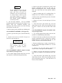
4-23. OIL PUMP ASSEMBLY (See Figure 4-18).
a. Loosen oil screen (6) and tachometer drive housing
(12) to facilitate later removal. (Tachometer drive
housing has a left hand thread.) Remove ten sets of
attaching parts (1, 2, 3) and pull pump assembly to the
rear. Remove gasket (5).
b. Remove oil screen (6) and gasket (7).
c. Remove attaching parts (8,9,10) and separate cover
(11) from pump housing (4). Remove tachometer
drive housing (12). Press oil seal (15) from housing.
Remove gasket (13) and tachometer drive shaft (14).
d. Remove oil pump drive gear assembly and separate
tachometer drive gear (33) oil pump drive gear (34)
and pin (35). Remove oil pump driven gear and
bushing assembly (36, 37).
e. Remove oil pressure relief valve (38 through 43).
Remove by-pass assembly (46 through 48).
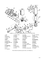
4-24. OIL PUMP ASSEMBLY, FULL FLOW (See
Figure 4-19).
a. Cut lockwire and remove filter (1). Remove
attaching parts (2,3,4) and separate adapter (5) and
gasket (6) from oil pump housing (10).
b. If electric tachometer (33 through 37) is used,
loosen tachometer housing (36) at this time. (Housing
has a left-hand thread.)
c. Remove attaching parts (12, 13, 14) and lift off
housing (15). Remove attaching parts (16,17, (18)
and (21,22,23) and remove covers (19) and (24).
Remove gaskets (20) and (25).
d. Remove oil seal (26) and shaftgear (27).
e. If electric tachometer is used, remove attaching
parts (30,31,32) and separate cover (33) from oil
pump housing (10).
Remove tachometer drive
housing (36), oil seal (35) and shaftgear (34).
i. Parts (51 through 65) have been replaced by a new
style spin on filter.
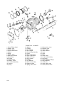
4-25. CYLINDERS AND PISTONS (See Figure
4-20).
a. Rotate engine stand so engine is in inverted
position. Remove attaching parts (1, 2, 3), cover (4)
and gasket (5).
b. Position crankshaft so valve lifters of cylinder to be
removed are on heels of cam lobes and both valves are
fully closed. Remove screw (6), washer (7), shafts
(8), rocker assemblies (9, 10, 11) and thrust washers
(12). Withdraw pushrods (13). Repeat these steps on
remaining cylinders.
c. Push the pushrod housing (14) against the spring
(15) until the cylinder flange end is clear. Lift
cylinder end of housing and withdraw from crankcase.
Remove spring (15), washers (16) and packing (17).
d. Remove two sets of attaching parts (18, 19) from
each cylinder flange. Rotate engine stand so engine is
in upright position. Make certain piston in cylinder to
be removed is top dead center. Remove nuts (19).
Cradle cylinder in arm and withdraw it straight
outward. Catch piston with other hand as it clears the
cylinder to prevent damage to piston or crankcase.
e. Remove piston pin (20) and piston (21) with rings
(22,23,24,25) as an assembly.
f. Remove packing (26). Use of a cylindrical wood
block anchored to a work bench, with provisions for
clamping the cylinder in place, is recommended to
facilitate removal of valve springs and to prevent
dropping of valves.
g. Lift out shaftgear assembly (38 through 40) and
driven gear assembly (41, 42).
g. Compress valve springs and remove keys (27). Be
careful not to cock retainers (28, 29) and score valve
stems. Remove rotocoil (28) or outer retainer (29),
outer spring (30), inner spring (31) and inner retainer
(32). Hold valve stems while lifting cylinder from its
support, and lay cylinder on its side. Stone down any
nicks before removing valve stems (33, 34). It is
recommended that all exhaust valves be replaced at
each major overhaul regardless of condition.
h. Remove oil pressure relief valve (43 through 50)
from oil pump housing.
h. Remove rings (22,23,24 and 25) from piston (21).
Be careful not to score ring lands with ring ends.
f. Remove attaching parts (7,8,9) and pull oil pump
assembly from crankcase studs. Remove gasket (11).
4-19
i. Remove hydraulic valve lifter assemblies (43). It is
recommended that all hydraulic lifters be replaced at
each major overhaul regardless of condition. If for
any reason lifters are removed for inspection before
the overhaul period is reached, they must be placed
back in the same location from which they were
removed.
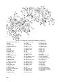
4-26. SANDCAST CRANKCASE (See Figure 421).
a. Oil gauge rod and guide and brackets (items 1
through 11) are shipped loose with the engine, and
were probably returned in the same manner. If not,
remove in the order of index numbers assigned.
b. Unhook filler cap retaining ring and remove oil cap
retainer assembly (12). Remove three screws (14) and
lift off oil filler neck (15) and gasket (16).
j. With a non-marring hammer, tap upper ends of
through bolts(54,55,56,57) and pull them downward
and out of the crankcase. Discard "O" rings.
k. Remove idler gear support pin attaching parts (58,
59) and hold idler gear while support pin (60) is
withdrawn. Lower gear to rest in left crankcase.
Remove gasket (61).
1. Remove attaching parts (62, 63, 64) and re- move
mounting brackets (65).
m. Lift off right crankcase subassembly.
n. Lift out camshaft assembly and governor driven
gear (See Figure 4-23).
o. Lift out idler gear assembly, crankshaft assembly
with connecting rods, thrust washers and bearings
(See Figure 4-19).
c. Remove attaching parts (17,18,19,20) and remove
lifting eye (21) and spacer (22).
d. Cut lockwire and remove oil temperature con- trol
valve (23).
e. Remove bolt (24), nut (27), lockwashers (25), plain
washer (26), plain washer (28), flanged nut (29) and
washer (30) to remove generator mount bracket (31).
f. Remove nut (32), lockwasher (33), plain washer
(30), spacer (35) and lift off governor pad cover (36)
and gasket (37).
g. Remove parts indexed (38 through 49).
h. Rotate engine disassembly stand bed so that left
crankcase (82) will be downward and support it as
illustrated in Figure 8-1.
i. Remove remaining crankcase-to-crankcase flange
bolts (50), nuts (51), lockwashers (52) and plain
washers (53).
NOTE
Do not attempt to remove bolt and
washer adjacent to right magneto up- per
stud. These two parts are installed before
the stud and cannot be removed before
removal of that stud without damage to
crankcase hole. Take care to avoid
damage to bolt threads during
subsequent overhaul operations.
4-20
4-27. PERMOLD CRANKCASE (See Figure 422).
a. Remove oil gauge rod (1). Remove attaching parts
(2, 3, 4) and detach oil filler tube (5), gasket (6) and
“O” ring (7).
b. Remove nut (8), washers (9, 10), bolt (11), lifting
eye (12) and spacer (13).
c. Remove nut (14), washers (15, 16), spacer (17) and
lift off governor pad cover (18) and gasket (19).
d. Remove camshaft hole cover attaching parts (20,
21, 22), cover (23) and gasket (24).
e. Rotate engine stand bed to place left crank- case
downward. Place a length of pipe or wood under the
left crankcase to support it during disassembly.
Remove right mount brackets (IO- 520-C only).
f. Remove two sets of attaching parts (25, 26), idler
gear flanged bushing (27) and gasket (28).
g. Remove attaching parts (29 through 57). Tap
crankcase through bolts (58 through 61) with a nonmarring hammer and remove carefully from crankcase
so as not to damage threads. Remove "O" rings (47).
NOTE
Do not attempt to remove bolt and
washer adjacent to right magneto
upper stud. These two parts are
installed be- fore the stud and cannot
be removed before removal of that
stud without damage to crankcase
hole. Take care to avoid damage to
bolt threads during subsequent
overhaul operations.
h. Lift off right crankcase. Lift out camshaft
assembly and governor driven gear (See Figure 4- 23).
Remove idler gear, crankshaft assembly with
connecting rods, thrust washers and main bearings
(See Figures 4-24 and 4-25).
i. Remove dowel pin (63) and idler gear bushing (64).
b. Remove cotter pin (5), slotted nut (6), bolt (7) and
separate connecting rod caps (8) and rods (9).
Remove all bearing inserts (10). Loosely reassemble
rods, caps, bolts and nuts with position numbers
matched.
c. Remove retaining rings (12), retaining plates (13)
and pins (14,15,16). Remove counterweights (17).
d. Remove nuts (19) and lift off governor oil transfer
collar (20 through 25).
e. Remove six screws (26), and pull gear (27) from
crankshaft.
f. Twist and remove split retainer ring, twist and
detach from seal (28). Work oil seal spring (29) from
its groove. Remove oil seal (30) from crank- shaft
(34).
4-28. CAMSHAFT ASSEMBLY (See Figure 4-2)
4-30. CRANKSHAFT (Typical of Permold Crankcase) (See Figure 4-25).
a. Remove governor drive gear (2) and Woodruff key
(3).
a. Use wooden support blocks under front and rear
journals of crankshaft during disassembly.
b. Remove four screws (4) and lift off gear (5).
(IO-520-A only) and gear (6).
b. Remove cotter pin (4), slotted nut (5), bolt (6), and
separate connecting rod cap (7) and rod (8). Remove
bearing inserts (9). Loosely reassemble rod, cap, bolt
and nut with their position numbers matched.
WARNING
Do not remove rear pipe plug (7) or
front expansion plug (8) from
camshaft in permold crankcase
engines.
4-29. CRANKSHAFT GROUP (Typical of Sandcast Crankcase) (See Figure 4-24).
a. Use wooden support blocks under front and rear
main journals of crankshaft during disassembly.
c. Remove retaining ring (11), plate (12) and pins (13,
14, 15). Lift counterweight assemblies (16, 17) from
crankshaft (35).
d. Remove nuts (18) and separate governor oil
transfer collar (19 through 23) from crankshaft.
e. Remove six screws (24) and gear (25). Remove
four bolts (26), lockplate (27) and alternator drive gear
(28).
f. Twist and remove split retainer ring, twist and
detach from seal (29). Work oil seal spring (30) from
groove and detach from seal. Twist and remove oil
seal (31) from crankshaft.
May 1980
4-21
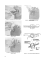
FIGURE 4-18. OIL PUMP (INTEGRAL TYPE OIL SCREEN).
1. Nut
2. Washer, Lock
3. Washer, Plain
4. Housing
5. Gasket
6. Screen Assembly
7. Gasket
8. Nut
9. Washer, Lock
10. Washer, Plain
11. Cover
12. Housing
13. Gasket
14. Shaftgear
15. Seal, Oil
16. Nut
17. Washer, Lock
4-22
18. Washer, Plain
19. Cover
20. Nut
21. Washer, Lock
22. Washer, Plain
23. Cover
24. Gasket
25. Seal, Oil
26. Gear Assembly
27. Screw
28. Washer, Lock
29. Washer, Plain
30. Cover
31. Gasket
32. Stud
33. Gear
34. Shaftgear
35. Dowel
36. Gear
37. Bushing
38. Nut, Adjusting
39. Washer
40. Housing
41. Gasket
42. Screw, Adjusting
43. Plunger
44. Spring
45. Washer
46. Pin and Plug Assy.
47. Gasket
48. Valve
49. Spring
50. Plug
51. Stud
52. Stud
FIGURE 4-19. OIL PUMP (PERMOLD ENGINE FULL FLOW TYPE FILTER).
1. Filter
2. Nut
3. Lockwasher
4. Washer, Plain
5. Adapter
6. Gasket
7. Nut
8. Lockwasher
9. Washer, Plain
10. Housing, Oil Pump
11. Gasket
12. Nut
13. Lockwasher
14. Washer, Plain
15. Cover
16. Nut
17. Lockwasher
18. Washer, Plain
19. Cover
20. Gasket
21. Screw
22. Lockwasher
23. Washer, Plain
24. Cover
25. Gasket
26. Oil Seal
27. Shaftgear
28. Stud
29. Stud
30. Nut
31. Lockwasher
32. Washer, Plain
33. Cover
34. Gasket
35. Oil Seal
36. Housing, Tach Drive
37. Shaftgear
38. Shaftgear
39. Gear
40. Dowel
41. Gear
42. Bushing
43. Stop Nut
44. Washer, Copper
45. Housing, Relief Valve
46. Gasket
47. Plunger
48. Spring
49. Washer, Spring Guide
50. Screw, Adjusting
*51. Bolt
*52. Lockwasher
*53. Washer, Plain
*54. Nut
*55. Lockwasher
*56. Washer, Plain
*57. Bracket
*58. Spacer
*59. Spacer
*60. Housing
*61. Stud
*62. Gasket
*63. Element, Filter
*64. Nut, Nylon Lock
*65. Adapter
*Parts have been replaced by spin-on filter (1) and adapter (5).
4-23
FIGURE 4-20. CYLINDER.
1. Screw, Fillister Head
2. Washer, Lock
3. Washer, Plain
4. Cover, Valve Rocker
5. Gasket
6. Screw
7. Washer, Plain
8. Shaft, Valve Rocker
9. Screw, Drive
10. Bushing
11. Rocker, Valve
12. Washer, Thrust
13. Push .Rod Assembly
14. Housing
15. Spring
4-24
16. Washer
17. Packing
18. Nut, Flanged
19. Nut, Flanged
20. Pin and Plug Assembly
21. Piston
22. Ring, Compression
23. Ring, Compression
24. Ring, Oil Control
25. Ring, Scraper
26. Packing
27. Key, Retainer
28. Roto Coil Assembly
29. Retainer, Intake
30. Spring, Valve, Outer.
31. Spring, Valve, Inner
32. Retainer, Inner
33. Valve, Intake
34. Valve, Exhaust
35. Insert
36. Insert
37. Stud
38. Guide, Valve
39. Head and Barrel Assy.
40. Nut, Brass
41. Gasket, Exhaust, Flange
42. Ring, Retaining
43. Valve Lifter
44. Insert, Intake Valve
45. Insert, Exhaust Valve
FIGURE 4-21. SANDCAST CRANKCASE ASSEMBLY COMPLETE.
1. Rod Assembly,
Oil Gauge
2. “O” ring
3. Nut, No. 10-32
4. Washer, Lock
5. Washer, Plain
6. Screw
7. Bracket
8. Clamp
9. Clamp, Hose,
Worm Type
10. Housing
11. Hose
12. Cap Assembly,
Oil Filter
13. Gasket
14. Screw
15. Neck Assembly,
Oil Filler
16. Gasket
17. Nut, Plain, Hex
18. Washer, Lock
19. Washer, Plain
20. Bolt
21. Eye, Engine Lifting
22. Spacer
23. Valve Assembly
24. Bolt
25. Washer, Lock
26. Washer, Plain
27. Nut, Plain, Hex
28. Washer, Plain
29. Nut, Flanged
30. Washer, Plain
31. Bracket, Generator
32. Nut, Plain, Hex
33. Washer, Lock
34. Washer, Plain
35. Washer
36. Cover, Gov. Pad
37. Gasket
38. Nut, Flanged
39. Spacer
40. Nut, Plain
41. Washer, Plain
42. Bolt
43. Washer, Plain
44. Washer, Plain
45. Nut, Plain, Hex
46. Washer, Lock
47. Washer, Plain
48. “O” ring
49. Bolt
50. Bolt
51. Nut, Plain, Hex
52. Washer, Lock
53. Washer, Plain
54. Bolt, Thru
55. Bolt, Thru
56. Bolt, Thru
57. Bolt, Thru
58. Nut, Plain, Hex
59. Washer, Lock
60. Pin, Idler
Gear Support
61. Gasket
62. Nut, Plain, Hex
63. Washer, Lock
64. Washer, Plain
65. Bracket,
Engine Mount
66. Screw
67. Clip, Oil Transfer
68. "0" Rings
69. Nozzle, Squirt
70. Ring, Retaining
71. Housing
72. Bearing, Needle
73. Plug, Machine Thread
74. Gasket, Copper
75. Insert, Thread
76. Plug
77. Plug
78. Plug
79. Breather
80. Screw, Drive
81. Plate, Identification
82. Crankcase, 2-4-6 Side
83. Crankcase, 1-3-5 Side
4-25
FIGURE 4-22. PERMOLD CRANKCASE ASSEMBLY COMPLETE.
1. Gauge and Cap Assy., Oil
2. Screw
3. Washer, Lock
4. Washer, Plain
5. Tube, Oil Filler Assy.
6. Gasket
7. “O” ring
8. Nut, Plain, Hex
9. Washer, Lock
10. Washer, Plain
11. Bolt
12. Eye, Engine Lifting
13. Spacer
14. Nut, Plain, Hex
15. Washer, Lock
16. Washer, Plain
17. Spacer, Gov. Pad
18. Cover, Gov. Pad
19. Gasket
20. Nut, Plain, Hex
21. Washer, Lock
22. Washer, Plain
23. Cover, Camshaft Hole
24. Gasket
25. Nut, Plain, Hex
26. Washer, Plain
4-26
27. Bushing, Flanged
28. Gasket
29. Nut, Flanged
30. Washer, Plain
31. Bolt
32. Washer, Lock
33. Washer, Plain
34. Bolt
35. Bolt
36. Washer, Lock
37. Washer, Plain
38. Bolt
39. Nut, Marsden, Lock
40. Washer, Plain
41. Bolt
42. Nut, Marsden, Lock
43. Washer, Plain
44. Nut, Plain, Hex
45. Washer, Lock
46. Washer, Plain
47. “O” ring
48. Bolt
49. Nut, Plain, Hex
50. Washer, Lock
51. Washer, Plain
52. Nut, Plain, Hex
53. Washer, Lock
54. Washer, Plain
55. Nut, Plain, Hex
56. Washer, Lock
57. Washer, Plain
58. Bolt, Thru
59. Bolt, Thru
60. Bolt, Thru
61. Bolt, Thru
62. "0" Ring
63. Dowel
64. Bushing, Idler Gear
65. Bearing, Needle
66. Plug, Machine Thrd.
67. Gasket, Copper
68. "0" Rings
69. Nozzle, Squirt
70. Plug, Pipe
71. Plug, Pipe
72. Plug, Pipe
73. Screw, Drive
74. Plate, Identification
75. Crankcase, 1-3-5 Side
76. Crankcase, 2-4-6 Side
77. Plug, Pipe
FIGURE 4-23. CAMSHAFT ASSEMBLY
1. Gear, Bevel, Driven
2. Gear, Bevel, Drive
3. Woodruff Key
4. Screw
5. Cam Gear
6. Gear, Camshaft
7. Plug, Pipe
8. Plug, Expansion
9. Camshaft
4-27
FIGURE 4-24. CRANKSHAFT GROUP (TYPICAL OF SANDCAST MODELS
1. Washer, Thrust
2. Bearing, Crankshaft, Main
3. Gear, Idler
4. Bushing, Idler Gear
5. Pin, Cotter
6. Nut, Slotted
7. Bolt, Special
8. Cap
9. Rod, Connecting
10. Bearing
11. Bushing
12. Ring, Retaining
13. Plate, Counterweight
14. Pin, Counterweight
15. Pin, Counterweight
16. Pin, Counterweight
17. Counterweight, Crankshaft
18. Bushing, Counterweight
4-28
19. Nut, Marsden
20. Collar, 1-3-5 Side
21. Collar, 2-4-6 Side
22. Sleeve, Oil Transfer
23. "0" Ring
24. Pin, Roll
25. Stud
26. Screw
27. Gear, Crankshaft
28. Spring
29. Reinforcing Ring
30. Seal
31. Bushing
32. Dowel
33. Plug, Oil Control
34. Crankshaft Group
FIGURE 4-25. CRANKSHAFT GROUP (TYPICAL OF PERMOLD CRANKCASE).
1. Washer, Thrust
2. Bearing, Crankshaft, Main
3. Gear, Idler
4. Pin, Cotter
5. Nut, Slotted, Special
6. Bolt
7. Cap
8. Connecting Rod Assembly
9. Bearing
10. Bushing
11. Ring, Retaining
12. Plate, Counterweight
13. Pin, Counterweight, 6th Order
14. Pin, Counterweight, 4th Order
15. Pin, Counterweight, 5th Order
16. Counterweight Assembly
17. Bushing
18. Nut, Marsden
19. Collar, 1-3-5 Side
20. Collar, 2-4-6 Side
21. "0" Ring
22. Dowel
23. Stud
24. Screw
25. Gear, Cluster
26. Bolt
27. Plate, Tab Lock
28. Gear, Face, Alt. Drive
29. Spring
30. Retaining Ring
31. Seal, Oil
32. Bushing
33. Dowel
34. Plug, Oil Control
35. Crankshaft and Tube Assy.
4-29/4-30
Intentionally Left Blank
SECTION V
CLEANING, REPAIR AND REPLACEMENT
5-1. MATERIALS AND PROCESSES.
5-2. Equipment, materials and processes in general
use in aircraft engine overhaul shops are satisfactory
for cleaning IO-520 engine parts.
5-3. Aluminum alloy parts can be degreased by
spraying with any fortified mineral spirit solvent or by
brush application of the same liquid. Fortified mineral
spirits are more effective when the parts are immersed
in them and allowed to remain for a short time to
permit solvent action to loosen caked deposits.
Carbon deposits and gum (oil varnish) may be
removed most easily by immersing these parts in a hot
bath of an inhibited, mild alkaline cleaning compound.
Immersion time should be only as long as necessary to
remove the deposits. Carbon solvent should be
employed only when carbon deposits are too hard and
thick for removal by other solvents. Give special
attention to cleaning studs, tapped holes and drilled
holes. Caution must be exercised in cleaning of all
aluminum alloy engine parts. Do not use any strong
alkaline solutions to clean aluminum alloy castings or
wrought aluminum alloy parts, because strong
solutions will attack and destruct a bare machined
surface. Immediately after removing soaking parts
from a caustic or inhibited, mild alkaline bath, remove
all traces of the alkali by spraying the parts with a jet
of wet steam or by brushing vigorously with a mineral
spirit solvent. Cleaned parts may be dried by use of a
jet of dry compressed air to remove all solvent liquids.
CAUTION
All alkaline residues must be
removed from crevices, recesses and
boles, as well as from other surfaces,
to prevent the formation of a
foaming emulsion in the engine
lubricating oil after reassembly.
5-4. No polishing compound or abrasive paste or
powder should be needed or employed for cleaning
engine parts. Scraping, abrasion with wire brushes,
sandpaper or abrasive cloth and buffing wheels are
dangerous methods to use on soft metals such as
aluminum. Scratches resulting from such methods
allow a concentration of stress at the scratch and may
cause fatigue failure.
5-5. Various blasting techniques can be employed to
remove hard carbon deposits if suitable equipment is
available. The most suitable types of grit for dry
blasting are plastic pellets and processed natural
materials, such as wheat grains and crushed fruit pits
or shells. Air pressure should be the lowest that will
produce the desired cleaning action. Small holes and
finished surfaces which do not require cleaning should
be protected from the blast by seals and covers,
particularly if the grit is sharp. Sand, shot and metal
grit are too abrasive and too heavy for use on soft
metals such as aluminum. After any blasting process,
blow off all dust with dry compressed air and make
sure that no grit has lodged in crevices, recesses and
holes.
5-6. SPECIFIC PARTS.
5-7. CYLINDERS. Precautions applicable to both
aluminum and steel must be exercised in cleaning and
storing these assemblies. Remove oil and loose
material with a mild alkaline cleaner by spraying or
brushing. If stubborn deposits of car- bon remain on
cylinder heads, the areas affected may be vapor
blasted. All machined surfaces must be protected from
abrasive action during the blasting operation.
5-6. PISTONS. Do not use wire brushes or scrapers
of any kind. Soft and moderately hard carbon deposits
may yield to solvent action. If deposits remain, blast
the heads with soft grit or by the vapor grit method,
first having installed tight fitting skirt protectors.
Ring grooves may he cleaned by pulling through them
lengths of binder twine or very narrow strips of crocus
cloth. Do not use automotive ring groove scrapers,
5-1
since the corner radii at the bottoms of the grooves
must not be altered, nor any metal removed from the
sides. Discoloration and light scoring need not be
removed from piston skirts. The use of abrasive cloth
on the skirts is not recommended, because the
diameters and cam-ground contour must not be
altered. Heavily scored or burned pistons should be
discarded.
5-9. VALVES. After degreasing valves, inspect
them and discard any whose head is warped
excessively, or which has insufficient stock to permit
refacing within specified limits, or whose stem is
burned, scored, eroded or nicked. Carbon deposits
may be loosened by solvent action or they may be
scraped off while the valve is rotated in a, polishing
head or lathe collet. Apply crocus cloth moistened in
mineral spirit, and polish the stems with dry crocus
cloth.
5-10. ROCKER SHAFTS. Degrease these parts by
brushing on any mineral spirit solvent. Prior to
magnetic inspection, polish the steel bearing surfaces
with crocus cloth moistened with kerosene, then with
dry crocus cloth.
5-11. PUSHRODS, VALVE ROCKERS AND
OTHER SMALL STEEL PARTS. Degrease these
parts with mineral spirit solvent, paying special
attention to removal of sludge from all oil passages.
5-12. CAMSHAFT AND CRANKSHAFT. All
parts may be degreased by brushing or spraying with
mineral spirit solvent. Pay particular attention to
threads, oil holes and recesses. Before magnetic
inspection, the crankpins, main journals, oil seal race
of the crankshaft and all journals, cam lobes and gear
mount flange of the camshaft must be smoothed with
crocus cloth, moistened in a mineral spirit. If
possible, this should be accomplished while shaft is
rotated in a high speed lathe (about 100 RPM). All
gum (varnish) deposits must be removed to permit
reliable magnetic indications.
NOTE
Internal cleaning of the hollow camshaft in
Permold engines is not necessary. Therefore, do
not remove the rear pipe plug or front expansion
plug unless re- placement of either plug is
necessary. Failure to replace either or both
plugs at reassembly will result in loss of oil
pressure with little or no lubrication of moving
engine parts.
5-2
MARCH 1982
5-13. CRANKCASE. The oil passages should be
pressure-flushed with mineral spirit solvent and
inspected with the aid of a flashlight. If the castings
are immersed in an alkaline bath, it is strongly
recommended that such treatment be followed by
spraying with a jet of wet steam and this followed by
flushing of the oil passages with solvent. After the
castings dry, inspect them thoroughly for alkaline
residues, and remove any traces of scum.
5-14. GEARS. Gears without bushings may be freed
of hard deposits by immersion in a caustic stripping
bath, when cold solvents are not effective. Bushings
are discolored by such treatment, hence bushed gears
should be cleaned by other methods such as spraying
and/or brushing with a mineral spirit solvent and
brushing with a brass wire brush.
5-15. SHEET METAL PARTS. Clean these parts
with a mineral spirit spray or by brushing with the
same liquid, or use a cold emulsion type cleaner and
flush with water to rinse.
5-16. Immediately after cleaning bare steel parts
spray them with or dip them in clean engine oil or, for
longer storage, in a corrosion-preventive oil mixture.
Wrap ball bearings in waxed paper. Wrap or cover
other clean parts to protect them from abrasive dust in
the air.
5-17. CASTINGS. Remove the raised edges of nicks
in machined surfaces with a hard Arkansas stone.
Unobstructed flat surfaces, such as valve rocker cover
flanges, may be returned to true flatness by lapping if
a true lap plate is available. Use fine grade lapping
compound and move the casting in a figure 8 stroke
without rocking it.
Gasket surfaces must be thoroughly cleaned with a
suitable hydrocarbon solvent such as naptha, Methyl
Ethyl Ketone (MEK) or Trichloroethylene (TCE) to
remove dirt, oil and grease. Wipe surfaces dry before
re-use.
5-18. STUD REPLACEMENT. Remove damaged
whole studs with a standard pattern stud remover or a
small pipe wrench, turning slowly to avoid heating the
casting. Remove broken studs which cannot be
gripped by drilling on center to the correct diameter
for unscrewing them with a splined stud extractor.
(Splined extractors and drills are usually sold in sets.)
Examine the coarse thread end of the damaged stud
before discarding it to determine its size. Standard
studs have no marking.
For oversize stud
identification refer to Table VII. Clean the casting
tapped hole with solvent and blow dry with
compressed air; then examine the thread. If it is not
TABLE VII. STANDARD AND OVERSIZE STUD IDENTIFICATION
torn, install the next larger oversize stud. If the old
stud was of the maximum oversize, of if the thread is
damaged, the hole may be tapped and a helical coil
insert installed for a standard-size stud. Coat the new
stud's coarse thread with Alcoa thread lube if the hole
is blind or with National Oil Seal compound if the
hole goes through to a cavity subject to oil spray. It is
advisable to drive the new stud with a tee handle stud
driver. Turn it in slowly, and compare the estimated
torque values listed in the Table of Limits. Drive the
stud in until it projects a distance equal to the
appropriate "Setting Height" listed in Table X.
5-19. HELICAL COIL INSERT INSTALLATION.
Bronze helical coil inserts are installed at the factory
in four tapped holes of each crankcase bottom flange,
in three holes in the left crankcase parting flange and
two in the right crankcase parting flange and in four
bolt holes at each cylinder head intake port flange.
Stainless steel helical coil inserts of special design are
installed in all spark plug holes. Any of these inserts
may be replaced, if damaged, with the aid of tools
which are available through Authorized Distributors
of the Heli-Coil Corp., Danbury, Connecticut 06810.
The manufacturer's Bulletin No. 650-R lists both
manual and power-driven installing tools, tang breakoff tools, special taps and plug gauges. A tap drill
bulletin is also available from the manufacturer.
Helical coil inserts are available in both National
Coarse and National Fine series in lengths equal to 1,
1-1/2 and 2 times nominal diameter and in pipe thread
sizes. They are made of either carbon steel, phospher
bronze or stainless steel, as specified by part number.
They are supplied with or without a notch above the
driving tang. The notch is provided to facilitate
breaking off the tang in open holes.
5-20. Helical coil inserts are helical coils of wire with
a diamond-shaped cross section forming both a male
and a female thread. The diameter of the insert, when
compressed into a special tapped hole at the widest
part of the wire (between male and female threads), is
equal to the nominal screw size. The special finishing
taps size the casting hole so that the pitch diameter of
the female thread of the installed insert conforms to
class 3 fit with standard bolt threads or class 4 (tight)
fit with standard-size studs. The difference in fit is
due to a difference in pitch diameters of bolts and
studs, so that only one set of helical coil special taps is
required for installation of these inserts in both bolt
holes and stud holes. Tap drilling depths and tapping
depth for helical coil inserts to be installed in blind
holes should conform to the recommendations relative
to inserts of length equal to 2 times nominal diameter,
as tabulated in the manufacturer's Bulletin No. 650-R.
Helical coil tap drills and special taps must be run in
perpendicular to the machined surface of the casting.
Drilling should be done in a drill press after the
casting is firmly supported and clamped and
alignment checked. The tap will tend to follow the
drilled hole. For drilling and tapping aluminum alloy
castings use a lubricant made by mixing one part lard
5-3
oil with two parts kerosene to prevent over heating of
the metal and tearing of the thread.
5-21. To remove a damaged helical coil insert use the
proper size of extracting tool for the nominal thread
size. Tap it into the insert so that the sharp edges get a
good "bite"; then turn the tool to the left, and back out
the helical coil until it is free. To install a new insert
in a properly tapped hole (after blowing out all liquid
and chips), slide it over the slotted end of the driving
mandrel of the proper size of installing tool and
engage the driving tang (bent end) of the helical coil
in the mandrel slot; then wind the insert slowly into
the tapped hole (See Figure 5-2). The outer end of the
insert should lie just within the first full thread of the
hole. Break off the driving tang of a notched helical
coil by bending back and forth across the hole with
long-nose pliers or with a special tang break-off tool.
5-22. CYLINDERS.
5-23. FIN REPAIRS. Straighten slightly-bent barrel
fins with long-nose pliers. File to smooth the edges of
broken head fins. If it becomes necessary to cut out a
vee notch to stop a head fin crack, a slotted drill
bushing to fit over the fin and a 3/16 inch twist drill
may be used to cut the notch. Its apex must be
rounded and the edges should also be rounded. If
such repairs and previous breakage have removed as
much as 10% of the total head fin area the cylinder
assembly has reached the limit of such repair.
5-24. SPARK PLUG HOLE HELICAL COIL
INSERTS. Before attempting to back out a damaged
insert, use a sharp pointed tool to pry the teeth at outer
end away from the cylinder head metal. Tap a helical
coil extracting tool into the insert until it has a good
bite (See Figure 5-3). Place a new helical coil in the
cut -out side of the installing tool sleeve with its
driving tang toward the threaded end. Engage the tang
with the slotted end of the driving mandrel and wind
the insert into the sleeve thread, thus compressing it.
Hold the sleeve so that the helical coil can be seen
through the slot in the threaded end, and turn the
mandrel crank until the insert starts into the cylinder
head hole. If the sleeve is then not in contact with the
head surface, grip sleeve and mandrel and turn until
the sleeve touches lightly (See Figure 5-4). Wind the
helical coil into the cylinder head until its toothed end
lies just within the first full thread. The teeth should
be in position to enter the depressions made by the
original insert. If driven too far, the insert will emerge
in the combustion chamber and will have to be wound
on through. When the helical coil is in correct
position, use long-nose pliers to bend the driving tang
back and forth across the hole until it breaks off at the
notch. Coat a Heli-Coil Corporation No. 520-2
5-4
expanding tool threaded end with Alcoa thread lube or
a mixture of white lead and oil, and screw it into the
new insert until its final thread forces the teeth firmly
into the cylinder head metal (See Figure 5-5).
5-25. VALVE GUIDES. If the valve guides are to
be replaced, the new guides must be installed so that
the valve stem hole is accurately square and aligned
with the valve seat. When pressing or driving out a
worn guide, the cylinder assembly should be firmly
supported in the inverted position with space below to
allow the guide to drop out. The driving tool should
pilot inside the guide and drive on its inner end. All
carbon must be removed from the guide's inner end.
If the cylinder head hole is not scored or enlarged, a
standard size guide may be installed as a replacement.
If the head hole is rough it must be broached or
reamed to a diameter smaller than the next larger
oversize guide by the amount of interference ("T")
specified in the Table of Limits. Valve guides are
supplied in oversizes of 0.005, 0.015 and 0.020 inch.
The cylinder assembly must be supported firmly while
the new guide is driven or pressed into place with a
driver which fits over its end and bears on the filleted
flange. Driving on the guide end will spread it.
Before installing a new guide, dip the end to be
inserted in engine lubricating oil. The flat side of the
guide flange must go against the cylinder head.
Watch for peeling of bronze and correct misalignment
which causes it. It is not necessary to freeze the new
guide before installing it. Valve guide broaches may
be purchased from the Borrough's Tool and
Equipment Company, Kalamazoo, Michigan. Sizes for
intake and exhaust valve guides are slightly different.
These tools are very expensive and may be broken
during the operation if not perfectly aligned with the
hole. They are intended for use in a broaching
machine not normally available in overhaul shops.
Valve stem holes may be reamed if solid spiral
reamers of correct diameters and with 0.431 inch
diameter pilots are available. (Refer to the Table of
Limits for stem hole finished sizes.)
NOTE
Due to the choke specified for the cylinder
barrel bore, a cam-controlled grinder is
required to regrind worn barrels to the
allowable 0.015 inch oversize dimension.
FIGURE 5-1. STANDARD CYLINDER ASSEMBLY DIMENSIONS
MAY 1980
5-5
FIGURE 5-2. INSTALLING TYPICAL HELICAL INSERT
FIGURE 5-3. REMOVING SPARK PLUG HOLE
HELICAL INSERT.
FIGURE 5-4. INSTALLING SPARK PLUG HOLE
HELICAL INSERT.
FIGURE 5-5. EXPANDING SPARK PLUG HOLE
HELICAL INSERT.
5-6
FIGURE 5-6. VALVE ROCKER BEARING DIMENSIONS
seized by score marks, the entire assembly must be
replaced. Remove spring by turning as if to unwind it
while pulling outward. Be careful not to stretch spring
out of shape. Remove check valve housing from
plunger with a small screwdriver by prying against
plunger shoulder. Do not flip off housing. After
housing is loosened lift off, and remove plate (4) and
spring (6).
5-28. CONNECTING RODS.
CAUTION
1.
2.
3.
4.
5.
6.
7.
Ring, Retaining
Socket, Hydraulic lifter
Plunger
Plate, Check Valve
Housing
Spring, Plunger
Body, Valve Lifter
FIGURE 5-7. HYDRAULIC LIFTER.
5-26. VALVE ROCKERS. Worn bushings may be
driven out with a suitable drift, and if properly
designed the same tool may be used to drive in new
bushings. The rocker must be supported on a ring
which will allow the old bushing to pass through.
Press the new bushing in flush with the rocker hub
after dipping it in clean lubricating oil. Ream the new
bushing to the specified diameter. It is advisable to
plug the oil holes with beeswax before reaming. Be
sure to remove the wax after reaming. Lightly break
the sharp edge at each end.
5-27.
HYDRAULIC VALVE LIFTERS (See
Figure 5-7). Stand valve lifter on its flat end. Use a
small screwdriver and carefully pry snap ring (1) from
body groove. Hold down socket (2) with a pushrod
until ring has been removed. Invert lifter and catch
socket as it drops out. Insert a finger into plunger (3)
and withdraw plunger (3), spring (6) and check valve
assembly (4, 5). If plunger is stuck in body (7), hold
plunger down fully and scrape out carbon deposit. If
this obstruction cannot be removed, or if plunger is
In order to assure good dynamic balance,
connecting rod assemblies for new engines
are selected in pairs with a maximum weight
variation of 1/2 ounce in opposite bays. This
limit cannot be main- tained if material is
removed from any of the original in a set. If
a connecting rod must be replaced, specify
the weight limits when ordering.
5-29. PISTON PIN BUSHING REPLACEMENT.
The connecting rod does not need to be heated for this
operation. Press out the old bushing in an arbor press,
using a drift only slightly smaller than the bushing
O.D. Make sure that the rod bore is smooth. Dip the
new bushing in engine lubricating oil before placing it
in position, and locate the split as illustrated in Figure
5-9. (The position number is stamped on the rod and
cap bosses on the far side.) Ream or bore the new
bushing to the specified diameter and check alignment
as described in paragraph 6-20. The center-to-center
distance given in Figure 5-8 will be held automatically
if the bore is centered in the new bushing.
5-30. CRANKSHAFT ASSEMBLY. Lightly scored
crankpins and journals may be smoothed with a hard
Arkansas stone. Do not use a coarser abrasive. Do
not attempt to remove deep scoring or indications of
overheating
which
render
the
crankshaft
unserviceable. Remove the upstanding edges of small
nicks on softer surfaces with a hard Arkansas stone.
Polish crankpins and main journals with long strips of
crocus cloth, preferably while the shaft is rotated
about 100 RPM in a lathe. Due to the fact that gears
are shrunk fit to the crankshaft, it may be necessary to
dip the gear in oil heated to 300°F. before removal can
be accomplished. These operations should precede
magnetic particle inspection.
5-7
FIGURE 5-8. CONNECTING ROD AND BUSHING DIMENSIONS.
5-31. Hardened steel bushings in the crankshaft
blades may be removed and replaced if excessively
worn. It may be necessary to chill the old bushings to
free them. New bushings must be chilled before
installation with a suitable drift, and the holes must be
smooth. No finishing operation is required for the new
bushings, since they are made to final dimensions.
They must be driven in to the same positions as the
original parts.
NOTE
Crankpins and crankshaft main journals
may be reground to the allowable 0.010
inch undersize.
CAUTION
Crankshaft counterweights are matched in
pairs with a maximum weight variation of 2
grams, and the complete crankshaft and
counterweights assembly is dynamically
balanced.
As
a
result,
ifeither
counterweight is damaged it will be
5-8
necessary to discard both on that cheek
and to procure a matched pair for
replacement.
5-32. IDLER GEAR. Replacement of excessively
worn idler gear bushings is not recommended, because
a special fixture is required to hold the gear during the
boring operation, in order to maintain the necessary
concentricity of the bushing hole and the gear pitch
circle.
5-33. MAGNETO AND ACCESSORY DRIVE
ADAPTER ASSEMBLY.
If the magneto and
accessory drive adapter bushing must be replaced, it
may be driven out with a 0.92 inch diameter drift
while the adapter boss is supported on a 1.12 inch 1.0.
ring; however, this procedure involves some chance of
scoring the adapter bore. A safer, though more
laborious procedure is to turn down the bushing flange
to the body diameter (0.942 inch) and to bore out the
bushing to a thin shell which can be collapsed. If this
method is used, take care not to cut into the end of the
adapter boss or to mark the adapter bore. Press in a
new bushing with an arbor press after dipping it in
Its flange thrust face must be parallel to the parting
surface within 0.002 inch (full indicator reading).
CAUTION
Before boring a new bushing, plug its oil
boles with beeswax to exclude cbips from
tbe adapter oil groove. Be sure to remove
the wax completely after the operation.
clean engine lubricating oil. The rear pad of the
adapter, rather than the studs, should be supported on
a parallel block and a flat block should be used to
exert pressure, unless the arbor has a perfect end.
Ream or bore the bushing to the specified diameter
then face the flange until it projects forward 1.4541.458 inch from the adapter parting surface. Chamfer
the bore at the flange end 1/16 inch deep on a 450
angle, and slightly break sharp edges at both ends.
The bushing hole must be concentric with the adapter
pilot shoulder within 0.002 inch and square with the
parting surface within 0.002 inch per inch of length.
5-34. In most instances the old seal may be driven out
with a 1/8 inch diameter pin punch inserted through
the four oblique oil holes in the bushing boss
alternately. If the seal is too tight for that method,
drill and tap two opposite machine screw holes in the
exposed flange of the seal case to match two screw
clearance holes in a pressure plate which can be laid
on the adapter studs. Run nuts on two long machine
screws; then insert the screws through the pressure
plate holes, and screw them into the holes tapped in
the seal. To avoid unnecessary stoning of the seal
bore, tighten the nuts against the plate to pull the seal
squarely from its recess. Smooth any scores in the
vacant adapter counter bore. Coat the periphery of a
new oil seal with lubricating grease, and press it into
the adapter with an arbor press and a flat end block of
1-3/8 inch diameter by 1-1/4 inch length.
5-35.
TACHOMETER DRIVE HOUSING.
Remove the oil seal with a suitable oil seal puller. If
the housing counterbore is scored, smooth it with
crocus cloth. Spread a film of Lubriplate grease on
the periphery of a new seal. Then press the seal
squarely into the housing with its lip pointed outward,
facing the oil source.
5-9
5-36. STARTER DRIVE ADAPTER. The clutch
spring sleeve is shrunk and doweled in the housing. If
it is necessary to remove the needle bearing in the
adapter, a removing driver may be made similar to the
driver illustrated in Figure 3-1.
Check oil feed holes to the starter adapter shaft- gear.
Hole diameter should be .0918-.0968 to reduce
possibility of clogging and causing lubrication loss to
starter adapter clutch spring. On sandcast crankcase,
hole is located off the rear main boss of the 1-3-5
crankcase half and enters the needle bearing
counterbore near the top of the holes at a 10 to 11
o'clock position. This hole can be enlarged, if
necessary, to the above dimension.
On permold crankcases, the oil feed hole comes off
the rear cam bearing of the 1-3-5 crankcase half and
intersects a very short hole in the center of the needle
bearing counterbore. Hole can be enlarged as above,
if necessary, after removal of the starter adapter.
5-37. OIL PUMP ASSEMBLY. Except for stoning
down nicks on parting flanges and replacement of
studs and worn parts, no repairs to the pump assembly
are possible. The pump driven gear shaft is pressed
into the pump housing and cannot be replaced
successfully. The pump gear chamber must not be
enlarged; hence, if it is scored the housing must be
discarded. Heavy scoring on the gear contact area of
the tachometer drive and pump cover renders this part
unserviceable, unless the parting surface can be lapped
smooth and perfectly flat.
5-38. IGNITION CABLES. Normally, all ignition
cable assemblies or harness assemblies should be
replaced at each overhaul. If the high tension outlet
plates are in good condition, new cable assemblies and
grommets may be installed on them and the cable ends
secured to the grommet of each harness with a brass
washer and a cable piercing screw, installed as in the
original assembly. If only the cable assemblies and
grommets are to be replaced, leave the cable clamping
bracket on the original cables of each harness, and
detach all cables from the high tension outlet plate by
removing the cable piercing screws from their ends in
the plate grommet. When the coupling nuts are
unscrewed the cables may be withdrawn and the
grommet removed from the plate. Observe the “1”
mark on the exterior side of each outlet plate adjacent
to the No.1 cable outlet hole. Refer to Figure 5-11
and observe that the numerals appearing at magneto
ends of the high tension cables correspond to the
consecutive order of outlet plate cable holes, while the
5-10
FIGURE 5-10. INSTALLING NEW STARTER
ADAPTER NEEDLE BEARING.
relative positions of spark plug elbows indicate the
installed positions of the cables.
Install cable
assemblies (3 through 14, Figure 5-11) in the
indicated positions in the two outlet plate and
grommet assemblies (1 and 2), starting with the proper
No.1 cable assembly in the marked hole of each plate,
and proceeding in consecutive order around the plates.
As each cable end is inserted, screw in the cable
coupling nut (33),and tighten it; then place one of the
brass washers (16) and a cable piercing screw (17) at
the grommet hole, and turn the screw in firmly but not
enough to cut the wire strands. When all cables have
been attached to the two outlet plates, locate a
clamping bracket (18) on the proper cables of each
harness in the same position as on the original cables,
and install a rivet (19) to secure it. Parts indexed 21
through 32 will be installed at final assembly. This
group should be collected and ready for installation.
Parts indexed 33 through 37 are installed on the
aircraft ignition switch wires. If replacement of spark
plug ends is necessary, proceed with disassembly as
indicated I (Items 38 through 45) for Slick Harness,
and (Items 46 through 52) for Bendix Harness.
FIGURE 5-11. EXPLODED VIEW OF IGNITION SYSTEM.
1. High Tension Cable Outlet Plate
2. Outlet Plate Grommet
3. Cable Assy. to No.1 Lower Spark Plug
4. Cable Assy. to No.6 Upper Spark Plug
5. Cable Assy. to No.3 Lower Spark Plug
6. Cable Assy. to No.2 Upper Spark Plug
7. Cable Assy. to No.5 Lower Spark Plug
8. Cable Assy. to No.4 Upper Spark Plug
9. Cable Assy. to No.1 Upper Spark Plug
10. Cable Assy. to No.6 Lower Spark Plug
11. Cable Assy. to No.3 Upper Spark Plug
12. Cable Assy. to No.2 Lower Spark Plug
13. Cable Assy. to No.5 Upper Spark Plug
14. Cable Assy. to No.4 Lower Spark Plug
15. Coupling Nut
16. Brass Washer
17. Cable Piercing Screw
18. Two-Wire Cable Bracket
19. Round-Head Rivet
20. Spark Plug Terminal Sleeve
21. Approved Spark Plug
22. Brace (Assembled on Crankcase)
23. Clip
24. Internal Tooth Lockwasher
25. Round-Head Screw
26. Magneto Gasket
27. Magneto
28. Magneto Holding Washer
29. Internal Tooth Lockwasher
30. Plain Hex Nut
31. Spring Lockwasher
32. Fillister-Head Screw
33. Hex Coupling Nut
34. Outer Ferrule
35. Inner Ferrule
36. Insulating Sleeve
37. Brass Washer
38. Spring
39. Screw, Electrode
40. Sleeve, Ignition Cable
41. Washer
42. Spring
43. Drive Ferrule
44. Drive Ferrule, Plug End
45. Nut, Spark Plug End
46. Nail
47. Sleeve
48. Elbow Assembly
49. Grommet
50. Ferrule, Cable, Inner
51. Ferrule, Cable, Outer
52. Nut, Spark Plug End
5-11/5-12
Intentionally Left Blank
SECTION VI
INSPECTION
6-1. DEFINITIONS OF TERMS.
6-2. The following definitions apply to terms used to
describe kinds of damage for which parts should be
inspected.
A. ABRASION: Scratching of a surface, either by
motion while in contact with another part or by
mechanical cleaning or resurfacing with abrasive cloth
or lapping compound.
B. BURNING: As applied to valve heads, this term
indicates roughening or erosion due to high
temperature gases escaping past valve faces. In other
instances it indicates drawing of the temper of steel
parts to a soft (blue) condition as a result of
overheating in absence of lubrication on moving
surfaces, such as gear teeth, subject to high loading.
C. BURR: A sharp projection of metal from an edge,
usually the result of drilling, boring, countersinking,
etc., but may also be caused by excessive wear of one
or both surfaces adjacent to the burred edge.
D. CORROSION: Deterioration of a surface,
usually caused by oxidation of metal.
E. ELONGATION: Stretching or increase in length.
F. FRETTING: Scuffing or deterioration of a metal
surface caused by vibration or chattering of/or against
another part. A fretted steel surface may appear dull,
scuffed or corroded, depending on length of time
subject to the action, dissimilarity and link of
contacting metal and presence or absence of moisture.
G. GALLING: Excessive friction between two
metals resulting in particles of the softer metal being
torn away and "welded" to the harder metal.
H. INDENTATION: Dents or depressions in a
surface caused by severe blows.
I. OXIDATIONS: Chemical combining of a metal
with atmospheric oxygen. Aluminum oxide forms a
tough, hard film and protects the surface from further
decomposition; however, iron oxides do not form
continuous cover or protect underlying metal, thus
oxidation of steel parts is progressive and destructive.
J. PITTING (OR SPALLING): Small, deep
cavities with sharp edges. May be caused in hardened
steel surfaces by high impacts or in any smooth steel
part by oxidation.
K. RUNOUT: Eccentricity or wobble of a rotating
part. Eccentricity of two bored holes or two shaft
diameters. A hole or bushing out of square with a flat
surface. Usually measured with a dial indicator, and
limits stated indicate full deflection of indicator needle
in one revolution of part or indicator support.
L. SCORING: Deep grooves in a surface caused by
abrasion when fine, hard particles are forced between
moving surfaces, as in a bearing and journal, or by
galling when a moving part is not supplied with
lubricant.
6-3. PROTECTION FROM CORROSION. Bare
steel should be covered with oil or a corrosion
preventive oil mixture except during the actual
inspection operations. Since inspection involves
handling of dry steel parts it is advisable to apply a
fingerprint remover solution after such handling,
particularly since perspiration and skin oils often have
a high acid content. Application of lubricating oil or
corrosion-preventive mixture will not necessarily stop
corrosion from this cause.
6-4. VISUAL INSPECTION: Parts without critical
dimensions and small parts, as well as running parts
and others of major importance, should be inspected
visually under good light for surface damage such as
nicks, dents, deep scratches, visible cracks, distortion,
burned areas, pitting, pick-up of foreign metal and
removal of enamel coating. Visual inspection should
also determine the need for further cleaning of obscure
MARCH 1982
6-1
areas.
Inspect all studs for possible bending,
looseness or partial removal. Inspect all threaded
parts for nicks and other damage to the screw threads.
After visual inspection the engine parts should be in
three groups: Apparently serviceable parts, repairable
parts and parts to be discarded.
6-5.
MAGNETIC PARTICLE INSPECTION.
Inspection by the Magnaflux method must be
conducted on all ferrous parts listed in Table XI, and
in accordance with the methods and data in the table
before dimensional inspection. The Magna-glow
method is recommended whenever the necessary
equipment is available.
This method employs
magnetic particles coated with a fluorescent organic
material which may be illuminated with a "black
light", as in the Zyglo process, to amplify weak
indications. If a crankshaft is doubtful after a circular
magnetization and inspection, demagnetize and
remagnetize it longitudinally for further inspection.
NOTE
Before magnetic particle inspection, piston pins and
valve rocker shafts must be polished with crocus
cloth.
CAUTION
Before magnetic particle inspection of any part, plug
small holes leading to obscure cavities with tightfitting wood plugs or with a hard grease which is
soluble in lubricating oil to prevent particles from
lodging in places from which they would be difficult
to remove and which places are not subject to visual
inspection.
After magnetic particle inspection,
remove all such plugs and clean the part thoroughly in
solvent; then dry with compressed air. Check for
complete demagnetization.
TABLE VIII
CRITICAL NEW PART DIMENSIONS
PART NAME
FEATURE
Cylinder Head
Rocker Shaft Boss Bore
Intake Valve Guide Bore
Exhaust Valve Guide Bore
NEW DIMENSION
(INCHES)
0.7495 - 0.7510
0.4352 - 0.4362
0.4370 - 0.4380
Valve Rocker Shaft
Outside Diameter
0.7490 - 0.7495
Valve Rocker Bushings
Inside Diameter
0.7505 - 0.7515
Intake Valve
Stem Diameter
0.4335 - 0.4340
Exhaust Valve
Stem Diameter
0.4335 - 0.4340
Piston (Standard)
*Diameter at Top
*Diameter Below 1St Groove
*Diameter at Bottom
Pin Bore Diameter
Third Ring Groove Width
Fourth Ring Groove Width
5.2030 - 5.2050
5.2180 - 5.2200
5.2405 - 5.2420
1.1246 - 1.1250
0.1910 - 0.1920
0.1000 - 0.1010
Piston Pin Assembly
Length (Including Plugs)
Diameter
5.2050 - 5.2200
1.1243 - 1.1245
Connecting Rod
Bushing Bore Diameter
Bushing Center-to-Crankpin Center
1.1267 - 1.1269
6.6230 - 6.6270
Crankshaft Assembly
Damper Pin Bushing I.D. (16)
0.6240 - 0.6260
6-2
MARCH 1982
PART NAME
Camshaft
Journal Diameter (4) Permold Crankcase
Journal Diameter (4) Sandcast Crankcase
NEW DIMENSION
(INCHES)
0.9980 - 0.9990
1.2480 - 1.2490
Hydraulic Valve Tappets
Outside Diameter
0.9990 - 0.9995
Crankcase
Camshaft Bearings Dia. Permold Crankcase
Camshaft Bearings Dia. Sandcast Crankcase
Crankshaft Bearing Bore in Crankcase Std.
Crankshaft Bearing Bore in Crankcase "B"
Configuration. Rear and Intermediate
Bearings Only.
Tappet Guides Dia.
Governor Driven Gear Bearing Dia.
Starter Shaft Needle Bearing Hole Dia.
1.0000 - 1.0010
1.2500 - 1.2510
2.5625 - 2.5635
Starter Worm Drive Shaft
Small End Diameter
Needle Bearing Hole in Starter Adapter
0.5615 - 0.5625
0.7485 - 0.7495
Starter Shaftgear
Front Journal Diameter
Knurled Drum Diameter
Clutch Drum Support Dia. Sandcast Crankcase
Clutch Drum Support Dia. Permold Crankcase
0.7495 - 0.7500
1.9310 - 1.9320
0.7870 - 0.7880
0.9995 - 1.0000
Starter Clutch Drum
Inside Diameter Sandcast Crankcase
Inside Diameter Permold Crankcase
0.7900 -0.7910
1.3115 - 1.3125
Starter Clutch Spring
Outside Diameter
Inside Diameter
2.3740 - 2.3760
1.9380 - 1.9400
Starter Drive Adapter
Sleeve Front End I.D.
2.3380 - 2.3430
Oil Pump Driver Gear
Shaft Diameter
0.5600 - 0.5605
Oil Pump Driven Gear
Shaft Assembly Hole Dia. Sandcast Crankcase
Shaft Assembly Hole Dia. Permold Crankcase
0.5620 - 0.5630
0.6870 - 0.6880
Oil Pump Housing and
Shaft Assembly
Driven Gearshaft Dia. Sandcast Crankcase
Driven Gearshaft Dia. Permold Crankcase
Driver Gearshaft Hole Diameter
Gear Chamber Depth Permold Crankcase
Gear Chamber Depth Sandcast Crankcase
0.5015 - 0.5025
0.5640 - 0.5650
0.5620 - 0.5630
1.3275 - 1.3290
2.6235 - 2.6250
Magneto Drive Gears
Shaft Diameter
0.8120 -0.8130
Magneto and Accessory
Drive Adapter
Idler Gear Assembly
Bushing Inside Diameter
0.7925 -0.7975
Bushing Inside Diameter Sandcast Crankcase
0.7900 -0.7950
Idler Gear Front Bushing
Bushing Inside Diameter Permold Crankcase
0.5600 -0.5610
Idler Gear Flanged Bushing
Bushing Inside Diameter Permold Crankcase
0.5010- 0.5020
Idler Gear Support Pin
Gear Support Diameter Sandcast Crankcase
0.8095 -0.8105
Idler Gear
FEATURE
Large Diameter Permold Crankcase
Small Diameter Permold Crankcase
* Measure piston diameters at right angles to pin bore.
2.8160 - 2.8170
1.0005 - 1.0015
0.8750 - 0.8760
0.9990 - 1.0000
0.5580 -0.5590
0.4990 -0.5000
MARCH 1982
6-3
6-6. FLUORESCENT PARTICLE INSPECTION.
This process, commonly known under the trade name
of "Zyglo", is recommended for inspecting aluminum
alloy parts for invisible cracks.
The standard
operating technique for the process is applicable.
6-7. DIMENSIONAL INSPECTION.
6-8. INSTRUMENTS. Areas of running parts and
bushings subject to wear should be inspected for
serviceable fit with mating parts by comparative linear
measurements and alignment measurements, using
standard pattern precision measuring instruments such
as micrometer calipers, telescoping gauges and dial
indicators. The use of a dial-type cylinder bore gauge
is recommended in preference to other tools not
specifically designed for this purpose.
6-9. DIMENSIONAL LIMITS. After comparative
measurements of mating parts and determination of
running clearance, refer to the Table of Limits,
Section VI, and to the Limits and Lubrication Chart to
locate the reference number of each fit and the
acceptable limits assigned to it. Limits under the
column heading "New Parts" are manufacturing
limits. All running clearances in this column apply to
mating parts, both of which are new, and the low limit
applies in all instances; however, such clearances are
allowed to increase with wear to, but not beyond, the
values in the column headed "Serviceable Limit". All
press and shrink fits must be maintained as specified
in the "New Parts" columns when the inserted member
is replaced. Oversize parts are supplied, in some
instances, to permit conformity to this requirement.
6-10.
ORIGINAL DIMENSIONS.
Although
comparative measurements of mating parts will
determine the serviceability of the fit, it is not always
easy to determine which part has worn the most, and
in some instances (e.g., main journals in new bearing
inserts), accurate measurements of fit are not possible.
While no limits of wear on critical dimensions have
been assigned to specific parts in most instances, it is
helpful in estimating wear to know the original
dimensions. Hence, the manufacturing limits in Table
VIII on important dimensions of new parts should be
consulted when the serviceability of a specific part is
in doubt.
6-11. PROTECTIVE COATING. The manufacturer protects all aluminum alloy castings, sheet metal
and tubing from corrosion by treating all surfaces, of
the parts, with "Alodine 1200" (American Paint and
Chemical Company, Ambler, Pennsylvania 19002).
6-4
6-12. APPLICATION OF "ALODINE 1200". In
the event the original finish of an aluminum part has
deteriorated or been removed, the part may be
"Alodized" or as described in "Alodine"
manufacturer's Technical Service Data Sheet No. AL1200-D. Wrought or die cast (smooth surface) parts,
such as valve rocker covers and intake tubes, are
tumble blasted prior to machining, if any, to roughen
surface before treatment. Such treatment should not
be employed in overhaul work on parts with machined
surfaces. "Alodine", unlike enamel or primer, will not
flake or peel off to contaminate engine lubricating oil;
therefore, corrosion protection can be afforded to all
interior aluminum surfaces and parts. If an enamel
coating is required for a part previously treated with
"Alodine", application of a primer before painting is
not necessary. "Alodizing" will be performed after all
machining and/or repair operations have been
completed. The surface color of an "Alodized" part
may vary from light gold to dark brown. When a part
is treated with "Alodine 1200" the thickness of the
film, or build up, on the mating or bearing surfaces is
so small that the effect on dimensional tolerances is
negligible.
6-13. REPAIR OF "ALODIZED" SURFACES.
If "Alodized" parts have been remachined, rubbed
with abrasives or scratched in handling so as to,
expose areas of bare aluminum, the surface may be
repaired by local application of "Alodine" solution in
the following steps:
a. Clean bare area thoroughly with carbon tetrachloride. Do not under any circumstances use an oil
base solvent or strong alkaline cleaner.
b. Mix a small quantity of hot water (180°F.) with 11/2 to 2 ounces of "Alodine 1200" powder to form a
paste, then gradually dilute with hot water until a
solution of one gallon is attained. This solution is to
be adjusted by addition of nitric acid to a PH value of
1.5 to 1.7.
c. Apply solution with a rubber set paint brush in such
a manner that solution flows over bare area. Allow
solution to remain on the part from one to five minutes
or until color of the new film is approximately same as
original.
d. Flush part with clear water and dry with warm air
current. Do not air blast or rub with cloth to dry new
film area. If color is too light, repeat step "C" until
desired color is obtained.
NOTE... If "Alodine" does not adhere to
metal a more severe cleaning method must be
used. A solution of 12 to 16 ounces of Oakite
No. 61, or equal per one gallon of water is
preferred. Apply and remove the solution
with caution because an alkaline cleaner of
this type will remove any "Alodine" film
previously applied.
Remove cleaning
solution thoroughly with plenty of hot water
and vigorous brushing.
face plate (supporting the front and rear main journals)
and rotated under a dial indicator placed to bear on the
center main journal in order to detect excessive
bending. This is of particular importance if the
aircraft has been involved in an accident resulting in a
broken or bent propeller. (Refer to the Table of
Limits for limits of "runout" at the center journal).
6-14. ENAMEL COATINGS. Ferrous parts when
painted with gold enamel will be baked with infrared
equipment for 15 minutes at 275-285° F. following
application of each coat. Magnesium parts will be
pickled and primed before painting; then baked with
infrared equipment for 15 minutes at 275-285° F.
following application of each coat of enamel.
a. Excessive localized brinelling of the crankshaft
dampener pin bushings can affect propeller blade tip
stresses. It is therefore recommended that at each
major overhaul the pin bushings be inspected and
replaced as required. This applies to both the
dampener bushings and the crankshaft blade bushings.
Worn or out of round counterweight bushing holes
will require counterweight replacements.
NOTE ...If a part which was originally
"Alodized" is to be refinished with enamel it
will not be necessary to apply zinc chromate
primer accept to the surface areas completely
stripped of "Alodine".
6-18. CRANKSHAFI' AND COUNTERWEIGHT
PINS AND BUSHINGS.
b. Inspect in the following manner: Measure the
inside diameter of bushing across points A, B and C.
Take the average of A and B and deduct this from C.
If the difference exceeds .001" then the bushing
should be replaced.
CAUTION ...Before application of primer
and enamel to a part, carefully mask all
connection joints and mating surfaces. No
primer or enamel is permissible on interior
surfaces of any parts contacted by engine
lubricating oil after assembly.
6-15. SPECIFIC INSPECTIONS.
6-16. CRANKCASE. If any cylinder base nut was
loose at disassembly or if any of the cylinder attaching
studs are bent, even slightly, or if there is definite
evidence that a cylinder was loose at any time, then it
is possible that reversal of stress has fatigued the studs
and through bolts installed on that cylinder pad, in
which case all of them should be replaced. Test for
bent studs with a toolmaker's square.
When
inspecting for casting cracks pay particular attention
to areas on and adjacent to the cylinder mount pads,
tappet guides, bottom flange and bearing bosses.
Look for nicks on machined surfaces and scoring in
shaft bearings and the shaftgear bushing. The castings
must be clamped together at all attaching points before
dimensional inspection of camshaft bearings.
1. The C measurement should be the point of
maximum diameter which is generally a point
perpendicular to the lengthwise centerline of the
crankshaft.
2. Measurements A and B should be taken at points
approximately 60° either side of Point C.
NOTE...If camshaft bearings are excessively
worn, the crankcase may be line bored for a
0.020 inch oversize camshaft.
3. After removing the bushings from the dampeners
or the crankshaft blades, measure the inside diameter
of the holes. Select a replacement
6-17. CRANKSHAFT. In addition to magnetic
particle, visual and dimensional inspection, the shaft
should be mounted on matched vee blocks on a sur-
bushing which will give an interference fit of 001"003" into each the dampener or the dampener or the
crankshaft blade holes.
JANUARY 1985
6-5
c. Replacement bushings are available in standard,
.0015", .003" and .005" oversize on the outside
diameter.
d. A special tool for removing and replacing these
bushings has been developed by Borroughs Tool and
Equipment Corporation, 2429 North Burdick Street,
Kalamazoo, Michigan. We recommend that this tool
only be used for these operations.
e. Counterweight pins are identified by dash numbers
stamped on one end. Because the damper order is
controlled by this pin diameter, it is imperative that
only the correct pin, properly identified, be used.
6-19. CAMSHAFT. Inspect the journal for scoring,
corrosion and overheating. Inspect lobes for pitting at
the toes and for evidence of overheating or unusual
wear.
NOTE...The following rework procedure is
for camshaft P/N 629726. See service bulletin
M86-14 or current revision as applicable.
Camshafts manufactured to Change letter A
thrn Z and AA are not qualified for the repair
procedure outline below and should not be
reworked or reused. Only camshafts with
Change Letter AB and after are qualified for
the repair procedure outlined below.
1.
Dress the outer edges of the cross holes,
approximately .010-.020, with the use of a Dremel
tool and emery wheel point No. 953 (or equivalent)
paying particular attention to the edge of the cross
hole where it intersects the fillet of the groove
2. Shot peen the entire groove including its radii
using SAE 330 shot to an intensity of .013 to .015
inches with an A2 strip.
3. Comply with all other procedures and inspection
requirements set forth in this overhaul manual
including, but not limited to, the procedures and
inspection requirements relating to magnetic particle
inspection and dimensional and visual inspection.
4. Identify reworked cams: vibro etch M86-14 after
the part number to show compliance with
6-6
FEBRUARY 1989
service bulletin M86-14 or current revision as
applicable.
WARNING ...The benefits of this repair
procedure may be negated if the camshaft
bearing surface or its supports in the
crankcase are worn so as to exceed
running clearance of .001 to .005 specified
in the table of limits section of this manual.
6-20. CONNECTING RODS. Use a telescoping
gauge and an outside micrometer caliper to measure
all worn bushings and locally replaced bushings. If a
bushing was replaced locally, it is also necessary to
check its alignment with the big end bearing seat. The
simplest method of making alignment measurements
requires a push fit arbor, preferably at least eight
inches long, for the bushing bore and another for the
bearing seat, a surface plate, two matched vee blocks
and two blocks of ground flat steel stock of equal
height. To measure twist, insert the arbors into the rod
bores; then lay the big end arbor in the vee blocks on
the surface plate, and place the ground steel blocks
under the ends of the bushing arbor at a measured
distance apart. A feeler gauge may be used to detect
any clearance at either end under the bushing arbor.
This, divided by the separation of the blocks in inches,
will give the twist per inch of length. (Refer to limit
in Section VI.) To measure bushing and bearing
convergence, mount a dial indicator on a surface
gauge, and swing the rod around the big end arbor to
the vertical position against a firm stop. Pass the
indicator over the bushing arbor at points an exact
number of inches apart. The difference in readings at
the two ends, divided by the distance between points
of measurements, again gives the misalignment per
inch, as specified in Section VI.
6-21. GEARS. Inspect gear teeth for signs of overheating and excessive wear. Normal wear produces a
fine polish on the tooth thrust faces. Alteration of the
tooth profiles, score marks and pitting are sufficient
cause for rejection.
6-22. PISTONS AND RINGS. Inspect the skirt for
long, deep scores which indicate overheating and are
sufficient cause for rejection. If a telescoping gauge is
used to measure the pin bore, do not allow the spring
pin to expand rapidly so as to strike the wall hard.
Inspect visually for thorough cleaning, including the
oil relief holes in the third ring groove. It is not
necessary to remove light scores or discoloration from
the exterior surfaces, and it is not advisable to use
abrasive (including crocus cloth) on the skirt, since the
FIGURE 6-1. INSPECTING RING SIDE CLEARANCE.
cam-ground contour should not be altered. If the
piston is dimensionally serviceable in other respects
and apparently sound, measure side clearances of new
rings (after measuring their gaps while squared in the
cylinder barrel) by installing the slotted oil control
ring assembly in the third groove, the two
compression rings in the top and second grooves and
the scraper ring in the fourth groove, with part
numbers toward the piston head, and inserting various
thickness gauges on either side of each ring (See
Figure 6-1). The gaps of rings in the barrel should be
measured first so that those selected may be left in the
piston grooves, if the grooves are not excessively
worn or distorted. When installing rings, take care not
to allow their sharp ends to scratch the piston lands. If
the cylinder barrel has not been ground oversize and
fits the piston within the allowable clearance limit, it
is permissible to install either standard or 0.005 inch
oversize rings, whichever have the specified gap, as
measured with the ring pushed up by the piston head
to a point in line with the base flange.
6-23. CYLINDERS. Measure the barrel bore near
the top of the ring travel limit and at the 5-1/4 inch
station from the open end in the thrust direction and at
right angles to that in order to detect out-of-roundness
and wear-in taper. There should be little or no wear at
the open end. Look for bent barrel fins and broken
head fins. Barrel fins can be straightened if not badly
bent or cracked. A reduction of not over 10% in area
of head fins due to breakage is allowable. Look for
cracked head fins, and specify repair of any radial
crack by drilling a vee notch to remove it. If a radial
crack extends to the root of a fin it may have
penetrated the wall; hence, the cylinder should be
rejected. If the cylinder base nuts were loose at
disassembly, or if the base studs were loose or bent,
test the machined side of the cylinder flange for
bending, which is cause for rejection. Measure valve
guides for wear, and look for scoring in their bores.
Valve seats should be inspected after refacing to make
sure that their outside diameters are still less than the
valve head diameters. Exhaust valves should be
checked for warpage before refacing, and all valves
should be measured in length if the stem tips were
ground. Inspect the spark plug hole and intake flange
screw hole helical coil inserts for looseness,
deformation and position. The outer ends should lie in
the first full thread of the tapped holes in which they
are installed. The spark plug hole helical coil has
teeth at the outer end which are forced into the head
metal and should not be visible. If there was any
evidence of overheating of cylinder or piston, check as
well as possible for turning of the head in relation to
the barrel flange. Security between cylinder head and
barrel is dependent on metal to metal contact of
cylinder barrel top threads within the head shoulder.
Dark stains at this area on both new and rebarreled
cylinders is generally due to emission of thread
lubricant used upon factory assembly of head to
barrel. Also, a very slight gas leakage in this area
causing the same condition generally stops of its own
accord when the gap fills with carbon during service.
Neither condition is detrimental to engine
performance or operation.
Due to IO-520 engine series cylinder design, however,
a persistent oil leak (not sealing compound) may
indicate the required pre-load at the head/ barrel
junction has been relieved and should be investigated
for possible cylinder replacement (See Service
Bulletin M69-7).
6-24. HYDRAULIC VALVE LIFTERS. During
examination of each part, look for sludge and carbon
residues. Also check for obstructed oil holes. Inspect
face of cam follower on body for any type of damage
and look for deep scoring and corrosion on exterior of
tubular portion. Discard any lifter body which
exhibits any of these faults. To test roughly for
excessive diametrical clearance between hydraulic
unit plunger and cylinder and to check valve wear in
cylinder, start dry plunger into dry cylinder. While
holding cylinder between thumb and middle finger,
depress plunger with index finger and release it
quickly. Compression of air in cylinder should make
plunger kick back instantly. If plunger does not return
6-7
fully, either it is excessively worn or check valve is
leaking.
To check for leaking valve, repeat
compression test while plugging end of oil inlet
tube with other hand. If plunger still does not kick
back promptly it and the cylinder are excessively
worn. If it does kick back on the second test, either
check valve seat is worn and leaking or it is dirty.
Clean cylinder again and repeat first test (tube
open). If plunger still does not kick back, valve is
defective. Any unit failing to pass this rough check
must be discarded. Discard both plunger and
cylinder, since these parts are selectively-fitted and
are not interchangeable.
6-25. INTAKE TUBES. Inspect intake tubes for
distortion, cracks and out-of-roundness. All other
types of damage will require replacement of the
part.
6-26.
LUBRICATION SYSTEM.
Visually
inspect all parts of the system in accordance with
the instructions in paragraphs 6-4, 6-8, 6-9 and
6-10.
6-27. FUEL INJECTION SYSTEM. Further
disassembly of the fuel injection system is not
recommended unless proper flow equipment is
available. For complete overhaul instructions see
Fuel Injection Overhaul Manual and Parts Catalog,
Form X-30091.
6-28.
IGNITION SYSTEM.
Teledyne
Continental Motors recommends replacement of the
complete ignition harness at every engine overhaul.
TABLE IX.
INSPECTION CHART
SUBASSEMBLY
AND PART
CYLINDER ASSEMBLY
HEAD & BARREL
6-8
INSPECT
NATURE OF INSPECTION
SPECIAL
CONSIDERATIONS
Head/Barrel Junction
Discoloration, Seepage.
See Section 5-22.
Interior Walls
Corrosion, pitting, scoring.
Defects not permissible
after removal of glaze.
Bore Diameters
Wear in ring traversed area
and step at top. Use dial-type
gauge set to zero near open
end of bore.
Refer to Table of limits for
standard size bore or for
over-size bore.
After honing or roughening of
glaze measure bore
diameters, out-of-roundness
and taper.
Dimensional honing should
re- move ring step of more
than 0.002 inch diameter.
Taper limit (Table of limits)
must not be exceeded by
honing.
Bore Walls
After roughening or honing,
inspect scratch pattern and, if
possible, measure surface
roughness in micro inches
RMS of 10% of cylinders as a
quality check.
Refer to Table of Limits.
Stem Holes in
Valve Guides
Scoring, diameter, flare at
ends.
Diameters of stem holes in
new guides must be within
limits for new parts and free
of tool marks.
SUBASSEMBLY
AND PART
INSPECT
NATURE OF INSPECTION
SPECIAL
CONSIDERATIONS
If seats cannot be made
serviceable by grinding
within width limit, replace
seat.
Valve Seats
Roughness caused by honing.
Cooling Fins
Cracks and broken areas.
Cracked and/or broken
cylinder head fins may be
re- paired, providing a total
of not more than five square
inches is, or has been
removed.
Base Flange
If attaching nuts were found
loose at disassembly, test for
flatness of mounting face.
Allow not over 0.001 inch
out-of-flat on machined
surface.
Pilot
Out-of-roundness of pilot
below face flange.
Spark Plug
Thread Insert
Distortion or improper fit in
cylinder head hole.
Pushrod Housing
Stems
Looseness, leakage.
Stems
Scoring, nicks in grooves,
wear on tips.
Heads
Use dial indicator to determine warp. Make sure that
grinding has not cut through
Stellite face of exhaust valve
or entered rounded edge on
intake valve head.
Length
Use height gauge to detect
stretch and check for reduction due to tip grinding.
Contact Foot
Scoring, diameter.
Oil Passages
Obstruction.
Hub
Side clearance between
cylinder head supports.
Outside Surface
Diameter, scoring, rough
ends.
Polishing must not reduce
diameter below minimum
for new parts.
Stretched valves may fail.
Shortened valve may
exceed ability of hydraulic
lifters to take up lash.
Refer to Table of limits
6-9
SUBASSEMBLY
AND PART
CONNECTING ROD
ASSEMBLY
Bushing
SPECIAL
CONSIDERATIONS
New bushings must be
reamed within diameter
limits for new parts. Sharp
edges must be broken
slightly. (Refer to Table of
Limits, for wear limit, for
new bushing limits and new
bushing alignment limits).
Diameters, scoring, burning
Must be polished before
magnetic inspection.
Crankpins
Diameters, scoring, burning
Must be polished before
magnetic inspection.
Oil Seal Race
Scoring
Must be polished
Screw Holes
Damaged or dirty threads
Oil Holes
Obstructions
Bending
Measure run-out at center
journal and wobble on face of
flange.
Gear Dowel
Tight Fit
Attempt to pull out by hand
only.
Oil Control Plug
Presence
Obstruction of oil hole, tight fit.
Gear
Teeth, Screw,
Threads
Burning, scoring, wear enough
to alter profile. Damaged or
dirty threads.
Journals
Diameter and fit in crankcase
bearings. Scoring, pitting and
corrosion.
Excessive bearing wear
may be compensated by
enlarging bearing and
installing oversize shaft.
Refer to “Crankcase”.
Lobes
Pitting along toe line, loss of
slope along toe line, width
across heel and toe at center
of length.
Serious pitting not
permissible. Toe line must
taper in relation of axis to
rotate valve lifters.
Flange Screw Holes
Distortion of threads.
End and Rear Face of
Flange
Nicks, peening, other
irregularities.
CAMSHAFT ASSEMBLY
Camshaft
Inside Diameter
NATURE OF INSPECTION
Measure with telescoping
gauge and micrometer caliper.
CRANKSHAFT
ASSEMBLY
Crankshaft
6-10
INSPECT
Main Journals
Required only if shaft has
been subject to shock.
Must be smooth to align
gear.
SUBASSEMBLY
AND PART
Gear
INSPECT
NATURE OF INSPECTION
SPECIAL
CONSIDERATIONS
Teeth
Scoring, burning, pitting, wear
enough to alter profile.
Valve Lifter Guides
Diameter, scoring.
Bearing Seats
Roughness, wear in tang
notches.
Refer to Table of Limits.
Camshaft Bearings
Diameter, scoring, fit of rear
bearing between camshaft
flanges.
See paragraph 6-16.
Oil Passages
Inspect visually, galleries,
main and camshaft bearing
supply holes, using inspector’s
flashlight to illuminate. Probe
other oil holes with brass rod.
Tapped Holes
Deformed or dirty threads.
Threads
Distortion.
Height
Check for backing outs.
Refer to Stud Height Table.
Squareness
Use toolmaker’s square to
check studs suspected of
bending.
Refer to Stud Height Table.
Idler Gear
Support and
Bushings
Bore
Inside diameter, scoring.
Refer to Table of Limits.
Needle Bearing
Rollers
Roughness or excessive play.
Retainer
Mounting Surface
Oil Seal
Warpage, cracks. Observe
that old seal has been
removed without damage to
retainer.
Oil Filler Neck
Tightness
Attempt to rock and pull out by
hand only.
Oil Gauge Rod
Distortion
Look for bent blade,
obliterated “FULL” and “LOW
marks, loose collar, deformed
cap.
Oil Gauge Support
Tightness
Attempt to move tube by hand
only.
Sandcast crankcase only.
Engine Mounting
Brackets
Machined Surfaces
Warpage and scratches.
Sandcast crankcase only.
All Areas
Cracks
Sandcast crankcase only.
CRANKCASE
ASSEMBLY
Crankcase Castings
Studs
Must be tight in casting
Permold crankcase only.
6-11
SUBASSEMBLY
AND PART
Plugs
NATURE OF INSPECTION
SPECIAL
CONSIDERATIONS
Threads
Look for distortion.
Wrench Flats
Look for damaged corners.
Bore
Inside diameter, scoring.
Sandcast crankcase only.
Seat
Roughness.
Sandcast crankcase only.
Headers, Fins
Core
Inspect visually for dents,
deformed fins, punctures,
stripped plug hole threads,
cracks and scratches.
Machined Surfaces
Warpage and scratches.
All areas
Cracks
Seat
Roughness
Tapped Holes
Damaged threads, cracks
around holes.
Mounting Surfaces
Scratches, warpage, cracks.
All Areas
Cracks.
Threads
Look for distortion
Wrench Flats
Look for damaged corners.
Oil Suction Tube
Threads, Tube
Filter
Damaged threads, dented
tube, cracks in tube, distorted
or plugged filter.
Engine Mounting
Brackets
Machined Surfaces
Scratches, cracks.
All Areas
Cracks, scratches on
machined surfaces,
restrictions in oil holes.
Gearshaft
Look for scoring, measure
diameter.
Plugs
Distorted threads, damaged
wrenching surfaces.
Oil Temperature
Control Valve
OIL COOLER
ASSEMBLY
Oil Cooler
Oil Temperature
Control Valve
OIL SUMP
ASSEMBLY
Casting
Plugs
OIL PUMP
ASSEMBLY
Housing
6-12
INSPECT
Permold Crankcase only.
Gears must turn freely.
(Refer to Table of Limits.)
SUBASSEMBLY
AND PART
Gears
INSPECT
NATURE OF INSPECTION
SPECIAL
CONSIDERATIONS
Refer to Table of Limits.
Shafts
Measure diameters and
compare with bushing
diameters.
Gear Teeth
Scoring, burning or wear
enough to alter tooth profile.
Splines
Look for wear on side of
splines and residual sludge.
Gear Bushings
Bore Diameters
Use telescoping gauge and
micrometer caliper.
Oil Pressure Relief
Valve Plunger
Outside Surface
Measure diameter. Look for
scoring, nicks, etc.
Conical Face
Roughness.
Oil Pressure Relief
Valve Housing
Plunger Seat
Spread Prussian blue oil base
pigment on face of plunger
and turn on seat, all around
plunger face must be lapped
to seat. (Plunger held
centered and aligned.)
Oil Pump Cover
Shaft Holes
Measure diameters.
Refer to Table of Limits.
Tachometer
Drive Housing
Threads, Flange
Seal Bore
Thread distortion, warped
mounting surface, scored seal
counterbore.
See that old oil seal was
removed.
Oil Filter Adapter
Threads Flange
Damaged threads, warped
flange, cracks.
Oil Filter
Threads, Screen
Pilot Cup
Damaged threads, punctured
screen, out-of-round pilot cup.
All Areas
Cracks, scratches on
machined surfaces, damaged
tapped holes.
Needle Bearing
Rollers
Roughness or excessive play.
Studs
Threads
Distortion or stripping.
Height
Check for backout.
Alignment
Check studs suspected of
bending with toolmaker’s
square.
STARTER ADAPTER
ASSEMBLY
Adapter
Refer to Table of Limits.
Must seat perfectly in
housing.
Refer to Stud Height Table.
6-13
SUBASSEMBLY
AND PART
Gears
INSPECT
NATURE OF INSPECTION
Shafts
Measure diameters and
compare with bushing
diameters
Gear Teeth
Scoring, burning or wear
enough to alter tooth profile.
Ball Bearing
Balls, Cage
Surface roughness, out-ofround, excessive depth and
looseness
Adapter Cover
All Areas
Cracks, scratches on
machined surfaces, damaged
mounting holes.
Shaft Bearing
Look for scoring.
Bore
Measure Diameter.
Oil Seal
See that old seal was
removed without damage to
casting.
ALTERNATOR
Hub Assembly
Hub
INDUCTION SYSTEM
Intake Manifold
FUEL INJECTION SYSTEM
Fuel Pump Adapter
6-14
Refer to Table of limits
Permold Crankcase Only.
All Areas
Scored or under bearing
surfaces.
Spring
Damaged or broken.
Gear
Look for chipped, cracked and
broken teeth, scoring, burning
and wear enough to alter tooth
profile.
Gear Bushing
Measure bore diameter.
Thrust Washer
Thickness, excessive wear.
Flanges
Check for warping by placing
flanges on surface plate.
Look for cracks.
Tubes
Look for dents, out-of-round
ends, cracks.
Damaged threads, cracks
around bosses.
Plug Bosses
Clamps
SPECIAL
CONSIDERATIONS
Shape
Look for distortion such as
out-of-roundness and lugs
converging.
All Areas
Cracks, damaged mounting
holes, inspect tapped holes.
Measure bore diameter.
Refer to Table of Limits.
Refer to Table of Limits.
SUBASSEMBLY
AND PART
Fuel Pump
Drive Gear
INSPECT
NATURE OF INSPECTION
Teeth
Look for chipped, cracked and
broken teeth, scoring, burning
and wear enough to alter tooth
profile.
Shaft
Measure outside diameter and
compare with bore diameter.
Gear Plug
Make sure that new plug was
installed after magnetic
particle inspection of gear and
visual inspection for
cleanliness of center bore.
Drive Coupling
Fit
Check for looseness.
Fuel Pump and
Vapor Separator
Assembly
Outside Area
Inspection is limited strictly to
visual for evidence of damage
or deterioration.
Shroud Assembly
All Areas
Inspect visually for dents,
cracks, and broken joints.
Air Throttle
Assembly
Tapped Holes
Damaged threads, cracks
around holes.
Studs
Bent or stripped stud threads.
All Areas
Cracks.
Shaft
Check alignment. Measure
diameter.
Plate
Check for warpage.
Fuel Discharge Tubes
All Areas
Look for cracks, flat spots,
out-of-round ends.
Pipe Fittings
Threads
Distortion or stripping.
Wrench Flats
Look for damaged corners.
SPECIAL
CONSIDERATIONS
Refer to Table of Limits.
See paragraph 6-27.
Fuel Injection
Control Assembly
Fuel Manifold
Valve Assembly
No wear limit established.
6-15
SUBASSEMBLY
AND PART
INSPECT
NATURE OF INSPECTION
SPECIAL
CONSIDERATIONS
MAGNETO AND
ACCESSORY DRIVE
ASSEMBLY
Adapter
Gear
6-16
Gear Bushing
Measure bore diameter.
Oil Seal
Observe that old seal has
been removed without
damage to casting bore.
Studs
Look for stripped and
deformed threads.
Teeth
Scoring, burning or wear
enough to alter tooth profile.
Shaft
Measure diameters and
compare with bushing
diameter.
Refer to Table of Limits.
Refer to Table of Limits.
TABLE X
CRANKCASE STUD SETTING HEIGHTS
LOCATION
Cylinder Mount Pads
Engine Mount Pads
Oil Cooler Mount Pads
Governor Mount Pad
Magneto Mount Pad
Magneto & Accessory
Drive Adapter Pad
Idler Pin Pad
Starter Drive Pad
Fuel Pump Pad
Oil Pump Pad
Generator Bracket
Camshaft Cover Pad
Crankcase Thru 1-3-5
Side Accessory End
Governor Oil Transfer
Collar
Cylinder Exhaust Flange
Oil Pump Housing
Oil Pump Cover
Magneto Adapter
Oil Sump
Starter Adapter
THREAD SIZE
7/16-14 X 7/16-20
3/8-16 X 3/8-24
3/8-16 X 3/8-24
3/8-16 X 3/8-24
3/8-16 X 3/8-24
3/8-16 X 3/8-24
3/8-16 X 3/8-24
1/4-20 X 1/4-28
3/8-16 X 3/8-24
3/8-16 X 3/8-24
5/16-18 X 5/16-24
5/16-18 X 5/16-24
5/16-18 X 5/16-24
SETTING
HEIGHT
13/16
1-7/32
1-1/4
1-49/64
1-1/2
1-13/16
1-7/8
7/8
49/64
27/32
5-7/8
1-3/8
43/64
A
36
15
1
----5
---4
4
B
36
-------2
2
1
4
4
C
36
--2
4
2
2
----4
4
MODEL IO-520
D
E
F
36 36 36
15 15 15
1
1
1
------------5
5
5
---------4
4
4
4
4
4
5/16-18 X 5/16-24
5/16-18 X 5/16-24
5/16-18 X 5/16-24
3/8-16 X 3/8-24
3/8-16 X 3/8-24
1/4-20 X 1/4-28
1/4-20 X 1/4-28
5/16-18 X 5/16-24
5/16-18 X 5/16-24
5/16-18 X 5/16-24
1/4-20 X 1/4-28
1/4-20 X 1/4-28
1/4-20 X 1/4-28
1/4-20 X 1/4-28
1/4-20 X 1/4-28
1/4-20 X 1/4-28
3/8-16 X 3/8-24
5/16-18 X 5/16-24
1/4-20 X 1/4-28
3/4
7/8
1-45/64
13/16
7/8
9/16
3/4
13/16
3-21/32
3/4
7/8
1-49/64
2-9/32
3-3/8
3-11/16
3-63/64
2-15/16
19/32
11/16
6
--2
2
-2
2
-2
1
-2
-2
5
-1
--
6
--2
-2
--2
--1
-5
--3
-2
3
1
2
2
-2
2
2
2
2
-1
-5
--3
---
6
--2
2
-2
2
-2
1
-2
-2
5
-1
--
6
---2
-2
2
-2
1
-2
-2
5
-1
--
5/16-18 X 5/16-24
5/16-18 X 5/16-24
5-13/32
6-13/32
---
1
--
-1
---
1/4-20 X 1/4-28
1/4-20 X 1/4-28
1/4-20 X 1/4-28
1/4-20 X 1/4-28
1/4-20 X 1/4-28
1/4-20 X 1/4-28
1/4-20 X 1/4-28
5/16-18 X 5/16-24
5/16-18 X 5/16-24
3/8-16 X 3/8-24
3/8-16 X 3/8-24
5/16-18 X 5/16-24
15/16
25/32
19/32
21/32
3/4
7/16
7/8
23/32
1
7/8
31/32
13/16
2
4
1
1
--4
--2
-2
2
4
-2
--4
3
2
2
12
--
2
4
-2
4
1
4
3
2
2
---
2
4
1
1
4
-4
--2
-2
J
36
15
1
----5
---4
4
K
36
15
1
----5
---4
4
L
36
15
1
----5
---4
4
6
--2
2
-2
2
-2
1
-2
-2
5
-1
--
6
--2
2
-2
2
-2
1
-2
-2
5
-1
--
6
--2
2
-2
2
-2
1
-2
-2
5
-1
--
6
--2
2
-2
2
-2
1
-2
-2
5
-1
--
---
---
---
---
---
2
4
1
1
4
-4
--2
-2
2
4
1
1
--4
--2
-2
2
4
1
1
--4
--2
-2
2
4
1
1
--4
--2
-2
2
4
1
1
--4
--2
-2
6-17
TABLE XI
MAGNETIC PARTICLE INSPECTION
FLUORESCENT METHOD PREFFERED,
WET CONTINUOUS PROCEDURE REQUIRED
*Method of
Magnetization
AC or DC
Amperes
Crankshaft
Circular and
Longitudinal
2000
Journals, fillets, oil holes,
thrust flanges, prop flange.
Fatigue cracks, heat
cracks, flange cracks,
from prop strike
Connecting Rod
Circular and
Longitudinal
1500
All areas.
Fatigue cracks.
Camshaft
Circular and
Longitudinal
1500
Lobes, Journals drilled
hole edges
Heat cracks.
Fatigue cracks.
Piston Pin
Circular and
Longitudinal
Shear planes, ends,
center.
Fatigue cracks.
1000
Pad, socket under side
arms and boss.
Fatigue cracks.
Part
Critical Areas
Possible Defects
On Conductor Bar
and Single
Between Heads
1000
Gears to 6 Inch
Diameter
Circular or
on Center
Conductor
1000 to
1500
Teeth, Splines, Keyways.
Fatigue cracks.
Gears over 6 Inch
Diameter
Shaft Circular
Teeth Between
Heads Two Times
90°.
1000 to
1500
Teeth, Splines.
Fatigue cracks.
Shafts
Circular and
Longitudinal
1000 to
1500
Splines, Keyways, Change
of Section.
Fatigue cracks, heat
cracks.
Thru Bolts
Rod Bolts
Circular and
Longitudinal
500
Threads Under Head.
Fatigue cracks.
Rocker Arms
800
NOTE: (*)
LONGITUDINAL MAGNETISM:
CIRCULAR MAGNETISM:
6-18
MAY 1980
Current applied to solenoid coil surrounding the work.
Current passed through work or through non-magnetic conductor
bar inserted through work.
TABLE XII
TABLE OF LIMITS
Ref.
No.
Chart
No.
Model
1
2
1
1
All
All
3
4
4
5
6
7
8
9
10
11
12
1
1
1
1
1
1
1
1
1
1
1
All
All
All
All
All
All
All
All
All
All
All
13
14
15
16
17
18
19
20
21
22
23
1
1
1
1
1
1
1
1
1
1
1
All
All
All
All
All
All
All
All
All
All
All
Description
CYLINDERS
Cylinder bore (lower end of barrel) ........................ Diameter:
Cylinder bore choke (at 5.75" from
open end of barrel). .............................................. Taper:
Cylinder bore out-of-round ...................................................:
Cylinder bore. ........................................ Allowable Oversize:
Cylinder bore. ........................................ Allowable Oversize:
Cylinder bore surface roughness. ................................RMS:
Cylinder barrel in crankcase. ................................. Diameter:
Intake valve seat insert in cylinder head. .............. Diameter:
Intake valve guide in cylinder head. ...................... Diameter:
Exhaust valve guide in cylinder head. ................... Diameter:
Exhaust valve seat insert in cylinder head. ........... Diameter:
Intake valve seat ........................................................ Width:
Exhaust valve seat ..................................................... Width:
Exhaust valve seat to valve guide axis. ...................... Angle:
Intake valve seat to valve guide axis .......................... Angle:
24
25
26
27
28
29
30
31
32
33
34
1
1
1
1
1
1
1
1
1
1
1
All
All
All
All
All
All
All
All
All
All
All
35
36
1
1
All
All
ROCKER ARMS AND SHAFT
Rocker shaft in cylinder head bosses. ................... Diameter:
Rocker shaft in rocker arm bearing. ...................... Diameter:
Rocker arm bearing in rocker arm.......................... Diameter:
Rocker arm .................................................. Side Clearance:
Intake valve in guide. ............................................. Diameter:
Exhaust valve in guide .......................................... Diameter:
Intake valve face (to stem axis) .................................. Angle:
Exhaust valve face (to stem ax is). ............................. Angle:
Intake valve (max. tip regrind .015) ...........................Length:
Exhaust valve (max. tip regrind .015). .......................Length:
Intake and exhaust valve (full indicator
reading) ......................................................Concentricity:
Valve rocker toe to valve stem (dry lifter) .............................:
Deleted
Piston (below 3rd ring groove) in cylinder. ............ Diameter:
Deleted
Top piston ring in groove. ............................ Side Clearance:
Second piston ring in groove. ...................... Side Clearance:
Third piston ring in groove. .......................... Side Clearance:
Fourth piston ring in groove. ....................... Side Clearance:
Top ring gap (in cylinder barrel) ....................................Gap:
Second ring gap (in cylinder barrel) ..............................Gap:
Third ring gap (in cylinder barrel) ..................................Gap:
Fourth ring gap (in cylinder barrel) ................................Gap:
Top and Second ring (standard gap). ................... Tension*:
Fourth ring (standard gap). ................................... Tension*:
Piston pin in piston (standard or 0.005 oversize) ... Diameter:
Deleted
37
38
1
1
All
All
Piston pin in cylinder. ...................................End Clearance:
Piston pin in connecting rod bushing. .................... Diameter:
Serviceable
Limit
Min.
New Parts
Max.
5.256
5.251
5.253
-0.003
5.266
5.271
-----------
0.001
0.000
5.261
5.266
15
0.004 L
0.009 T
0.0010T
0.0010T
0.0070T
0.017
0.120
45° 00'
59° 30'
0.003
0.002
5.263
5.268
25
0.010 L
0.012 T
0.0025T
0.0025T
0.0100T
0.156
0.171
45° 30'
60° 00'
0.003 L
0.004 L
-0.035 L
0.005 L
0.006 L
--4.789
4.791
0.0000
0.0010L
0.0020T
0.002 L
0.0012L
0.0030 L
59° 45'
45° 00'
4.804
4.806
0.0020L
0.0025 L
0.0040T
0.015 L
0.0027 L
0.0045L
60° 15'
45° 30'
4.824
4.826
0.004
0.000
0.060
0.002
0.200
0.027 L
0.010 L
0.013 L
0.008 L
0.008 L
0.0075L
0.012 L
0.059
12 Ibs.
8 Ibs.
0.0015L
0.004 L
0.004 L
0.0035 L
0.0060L
0.033
0.030
0.021
0.033
13 Ibs.
9 Ibs.
0.0001 L
0.006 L
0.006 L
0.0055 L
0.0080L
0.044
0.046
0.032
0.049
17 Ibs.
13 Ibs.
0.0007 L
0.090 L
0.0040 L
0.036 L
0.0022 L
0.048 L
0.0026L
* Measure piston ring tension on diameter perpendicular to gap when ring is compressed to specified inch gap.
MARCH 1982
6-19
Ref.
No.
39
40
41
42
43
**
Chart
No.
1
1
1
1
1
Model
Description
All
All
All
Bushing in connecting rod. .................................... Diameter:
Bolt in connecting rod ............................................ Diameter:
Connecting rod bearing on crankpin
(tri-metal bearing) ............................................ Diameter:
Connecting rod on crankpin .........................End Clearance:
Connecting bearing and bushing............................................
.................... Twist or Convergence Per 1 inch of Length:
CRANKSHAFT
Crankshaft in main bearings (tri-metal). ................ Diameter:
Crankpins .......................................................Out-of-Round:
Main journals. .................................................Out-of-Round:
Crankshaft main and thrust journals (STD) ........... Diameter:
Crankshaft rear and intermediate bearing for "B" model
engines ............................................................ Diameter:
Crankpins .............................................................. Diameter:
Crankshaft run-out at center main journals
(shaft supported at thrust and rear journals)
......................................................Full Indicator Reading:
Crankshaft run-out at propeller flange (when
supported at front and rear main journals)
......................................................Full Indicator Reading:
Damper pin bushing in crankcheek extension ....... Diameter:
Damper pin bushing in counterweight. .................. Diameter:
Damper pin bushing bore in counterweight
and crankshaft hanger. ...................................... Diameter:
Damper pin (4thOrder) .......................................... Diameter:
Damper pin (5th Order) ......................................... Diameter:
Damper pin (6th Order) ......................................... Diameter:
Damper pin in counterweight. ......................End Clearance:
Crankcheek in counterweight. ..................... Side Clearance:
Alternator gear on crankshaft. ............................... Diameter:
Crankshaft gear on crankshaft. ............................. Diameter:
Crankshaft in thrust bearing. ........................End Clearance:
Crankshaft in thrust bearing. ........................End Clearance:
Oil transfer collar on crankshaft. ............................ Diameter:
CAMSHAFT
Camshaft journals in crankcase. ........................... Diameter:
Camshaft in crankcase. ................................End Clearance:
Camshaft run-out at center journals (shaft
supported at end journals) ...........Full Indicator Reading:
Camshaft gear on camshaft flange. ...................... Diameter:
Governor drive gear on camshaft. ......................... Diameter:
Governor drive gear on camshaft. ......................... Diameter:
CRANKCASE AND RELATED PARTS
Crankcase oil seal in crankcase (split seal) .......... Diameter:
Through bolt (10.75") in crankcase. ...................... Diameter:
Hydraulic tappet in crankcase. .............................. Diameter:
All
All
44
45
46
47
2/3
**2/3
**2/3
2/3
All
All
All
All
48
49
2/3
2/3
All
All
50
2/3
All
51
52
53
2/3
2/3
2/3
All
All
All
54
55
56
57
58
59
2/3
2/3
2/3
2/3
2
3
All
All
P
All
S
P
All
60
61
62
2/3
2/3
2/3
All
All
All
63
64
65
2/3
2
3
All
S
P
66
67
68
2/3
2/3
1
All
All
All
Serviceable
Limit
---
New Parts
Min.
Max.
0.0025T
0.0050T
0.0018L
0.0000
0.006 L
0.016
0.0009 L
0.006
0.0034L
0.010
0.001
0.0000
0.0005
0.0050
0.0015
0.0015
2.372
0.0005L
0.0000
0.0000
2.374
0.0035L
0.0005
0.0005
2.375
2.623
2.247
2.624
2.249
2.625
2.250
0.015
0.000
0.015
0.005
---
0.000
0.0015T
0.0015T
0.005
0.0015T
0.0030T
0.6265
0.4735
0.5265
0.5549
0.040
0.017
--0.022
0.020
0.622
0.474
0.527
0.5554
0.001
0.005
0.0005 L
0.000
0.008
0.008
0.0005
0.626
0.475
0.528
0.5574
0.025
0.011
0.0035L
0.002
0.018
0.016
0.0018
0.005 L
0.014
0.001 L
0.005
0.003 L
0.009
0.001
-0.006 L
0.006 L
0.000
0.0005T
0.0002 L
0.001 L
0.001
0.0015L
0.0020L
0.003 L
--0.0035L
0.000 T
0.0005T
0.0015L
0.004 T
0.0013L
0.0020L
If crankshafts are worn beyond these limits they may be repaired by grinding crankpins and journals to
0.010” under new shaft limits and renitriding the crankshafts.
If these limits are exceeded, new bushings, pins and retaining plates must be installed to maintain proper
crankshaft dampening (paragraph 6-17).
P Permold Crankcase
S Sandcast Crankcase.
6-20
JANUARY 1992
Ref.
No.
70
70
71
72
73
Chart
No.
3
2
3
2
3
Model
Description
All
S
P
S
P
Governor drive shaft in crankcase. ........................ Diameter:
Idler gear support pin in crankcase (front). ........... Diameter:
Idler gear support bushing in crankcase (front) ..... Diameter:
Idler gear support pin in crankcase (rear) ............. Diameter:
Idler gear support bushing, flanged,
in crankcase (rear) ........................................... Diameter:
Magneto and accessory drive adapter
pilot in crankcase ............................................. Diameter:
Oil pump housing pilot in crankcase. ..................... Diameter:
74
4
All
75
2
All
76
2
All
77
78
79
80
81
82
2
2
3
3
2
3
S
S
P
P
S
P
83
4
All
84
4
All
85
86
87
87
88
4
4
4
4
4
All
All
S
P
All
89
4
All
90
4
S
90
4
P
91
4
All
92
93
94
95
96
97
2
3
2/3
2/3
2/3
2/3
S
P
All
All
All
All
98
2/3
All
Serviceable
Limit
0.005 L
0.0010L
---
New Parts
Min.
Max.
0.0034L
0.0014L
0.0015 L
0.0005 L
0.0015 L
0.0005 L
0.0025 L
0.0005 L
--
0.0015L
0.0035L
---
0.000
0.001 L
0.003 l
0.003 L
OIL PRESSURE RELIEF VALVE ASSEMBLY
Oil pressure relief valve adjusting screw
in plunger ......................................................... Diameter:
0.0030 L
0.0005 L
0.0020 L
ACCESSORY DRIVE IDLER ASSEMBLY
Bushing in idler gear ............................................. Diameter:
Idler gear support in bushing. ................................ Diameter:
Idler gear in support bushing (front). ..................... Diameter:
Idler gear in support bushing (rear) ....................... Diameter:
Idler gear ......................................................End Clearance:
Idler gear ......................................................End Clearance:
-0.0050 L
0.0040L
0.0040L
0.043
0.075
0.001 T
0.0015 L
0.001 L
0.001 L
0.002
0.020
0.003 T
0.0035 L
0.003 L
0.003 L
0.033
0.067
--
0.001 T
0.004 T
0.0050L
-----
0.0015 L
0.007 T
0.004 T
0.0015 L
0.011 L
0.0035 L
0.001 T
0.001 T
0.0086 L
0.077 L
0.055 L
0.025 L
0.040 L
0.040 L
0.0082 L
0.0182 L
--
0.010 L
0.052 L
---
0.014 L
0.001 L
0.052 L
0.005 L
0.0060L
0.0070L
0.0045 L
0.0050
0.0050
0.0015L
0.003 L
0.0015 L
0.0011
0.0011
0.0040L
0.005 L
0.0030 L
0.0030
0.0030
0.0045 L
0.0015 L
0.0030 L
0.0040 L
0.0005 L
0.0025 L
LEFT AND RIGHT MAGNETO AND ACCESSORY
Bushing in magneto and accessory
drive adapter ......................................................... Diameter:
Magneto and accessory drive gear in
adapter bushing ............................................... Diameter:
Oil seal in adapter ................................................. Diameter:
Sleeve in magneto and accessory drive gear. ...... Diameter:
Magneto and accessory drive gear. .............End Clearance:
Magneto and accessory drive gear. .............End Clearance:
Magneto coupling retainer on magneto
and accessory drive gear sleeve. .................... Diameter:
Magneto coupling retainer in magneto
drive gear slot Side ........................................ Clearance:
Magneto coupling rubber bushings
on magneto drive lugs. .......................... Side Clearance:
Magneto coupling rubber bushings
on magneto drive lugs. .......................... Side Clearance:
Magneto pilot in crankcase. ................................... Diameter:
OIL PRESSURE PUMP ASSEMBLY
Oil pump driver gear in pump housing. ................. Diameter:
Oil pump driver gear in pump housing. ................. Diameter:
Oil pump driver gear shaft in pump housing. ......... Diameter:
Oil pump driven gear in pump housing. ........End Clearance:
Oil pump driver gear in pump housing. ........End Clearance:
Oil pump driver gear shaft in cover
oil pump ........................................................... Diameter:
Oil pump driver gear shaft in tachometer
drive bevel gear ............................................... Diameter:
P Permold crankcase.
S Sandcast crankcase.
6-21
Serviceable
Limit
Ref.
No.
99
100
101
102
Chart
No.
2/3
2/3
2
3
Model
Description
All
All
S
P
Oil pump driven gear shaft in oil pump housing ........ Diameter:
Oil pump driven gear on shaft. .................................. Diameter:
Oil pump driven gear in housing. ............................... Diameter:
Oil pump driven gear in housing................................ Diameter:
-0.0040L
0.0045 L
0.0070L
103
104
2/3
2/3
TACHOMETER DRIVE ASSEMBLY
Tachometer drive shaft in oil pump cover. ................ Diameter:
0.0045 L
0.0015L
0.0030L
105
2
All
ABDF
JKL
CE
Oil seal in tachometer drive housing. ........................ Diameter:
Oil seal in tachometer drive housing. ........................ Diameter:
---
0.001 T
0.0015T
0.007 T
0.0065T
106
107
108
109
110
111
112
113
114
115
116
117
118
119
120
121
4
4
4
4
4
4
4
4
4
4
4
4
4
4
4
4
All
All
S
P
All
All
S
All
S
All
S
P
All
All
All
All
0.0031L
0.748
0.0055L
-------0.080
0.025
0.012T
0.013L
0.027T
0.0005 L
0.7495
0.001 L
0.0005 L
0.003 T
0.0001 L
0.0000
0.0010L
0.0017T
0.001 L
0.0426
0.0016
0.015 T
0.006 L
0.031 T
0.0015 L
0.7500
0.004 L
0.0020 L
0.005 T
0.0005 L
0.0015
0.0001L
0.0063T
0.003 L
0.0736
0.0166
0.022 T
0.009 L
0.038 T
122
123
124
125
126
127
128
4
4
4
4
4
4
4
All
All
All
All
All
All
All
STARTER DRIVE
Starter shaftgear in needle bearing. .......................... Diameter:
Starter shaftgear front (bearing) journal. ................... Diameter:
Starter clutch drum on starter shaftgear .................... Diameter:
Starter shaftgear in clutch drum bearing. .................. Diameter:
Clutch spring sleeve in starter adapter. ..................... Diameter:
Starter shaftgear in ball bearing. ............................... Diameter:
Starter shaftgear in oil seal sleeve. ........................... Diameter:
Bearing in starter adapter cover. ............................... Diameter:
Oil seal in starter adapter cover. ............................... Diameter:
Starter adapter cover pilot in starter adapter. ............ Diameter:
Worm wheel gear .............................................End Clearance:
Worm wheel gear .............................................End Clearance:
Clutch spring on clutch drum. .................................... Diameter:
Clutch spring on starter shaftgear (over knurl) .......... Diameter:
Clutch spring in clutch spring sleeve. ........................ Diameter:
From center line of worm gearshaft to
starter adapter thrust pads. .................................................:
Ball bearing in starter adapter. .................................. Diameter:
Worm gearshaft in needle bearing. ........................... Diameter:
Worm gearshaft in ball bearing. ................................ Diameter:
Starter worm gear on shaft. ....................................... Diameter:
Starter spring on worm driveshaft ............................. Diameter:
Starter pilot to starter drive adapter. .......................... Diameter:
Starter drive tongue to worm shaft drive slot. .. Side Clearance:
0.252
-0.5600
-0.0040L
--0.030L
0.246
0.0010L
0.5615
0.0001L
0.0005L
0.005 L
0.001 L
0.010 L
0.248
0.0001T
0.5625
0.0007T
0.0025L
0.025 L
0.0065 L
0.021 L
129
130
131
132
3
3
3
3
S
S
P
P
FUEL PUMP
Fuel pump drive coupling to fuel pump drive ........... Clearance:
Fuel pump drive coupling to fuel pump drive gear .. Clearance:
Fuel pump drive coupling to fuel pump. .................. Clearance:
Fuel pump drive coupling to crankshaft gear .......... Clearance:
0.0035
0.0035
0.0030
0.0095
0.0095
0.0095
0.0090
0.0155
133
134
135
4
4
4
All
All
All
0.016
0.016
0.008
0.008
0.012
0.012
136
2/3
All
0.016
0.016
0.008
0.009
0.012
0.013
GEAR BACKLASH
Crankshaft gear and camshaft gear. ......................... Backlash:
Crankshaft gear and idler gear. ................................. Backlash:
Idler gear and magneto drive gear
(right and left) ....................................................... Backlash:
Oil pump driver and driven gears. ............................. Backlash:
P Permold crankcase.
S Sandcast crankcase.
6-22
New Parts
Min.
Max.
0.003 T
0.001 T
0.0025L
0.0005L
0.0040L
0.0015L
0.0050L
0.0030L
Ref.
No.
137
Chart
No.
3
Model
138
139
140
141
142
4
4
2
3
3
All
All
S
P
P
143
2
S
144
3
P
2
S
2
S
3
P
2
S
3
P
145
146
2
2
All
S
147
1
All
1
All
1
All
1
All
148
C
Description
Tachometer drive gear and tachometer
driven gear ........................................................... Backlash:
Starter shaftgear and crankshaft gear. ...................... Backlash:
Starter worm wheel gear and worm gear. ................. Backlash:
Governor drive gear and governor driven gear. ........ Backlash:
Governor drive gear and governor driven gear. ........ Backlash:
Alternator face gear in engine. .................................. Backlash:
SPRING TEST DATA
Oil temperature control valve 0.16 inches
minimum travel at .......................................... Temperature:
Oil temperature control valve 0.090 inches
minimum travel at .......................................... Temperature:
Oil temperature control valve to flow
4 gpm of oil between. ......................................Oil Pressure:
Oil temperature control valve must close
between ....................................................Oil Temperature:
Oil temperature control valve must close
between ....................................................Oil Temperature:
Oil temperature control valve at oil temperature 180°
must not open below ............................................ Pressure:
Oil temperature control valve at oil temperature 180°
must not open below. ........................................... Pressure:
Relief valve spring compressed to 1.25 in. length ............Load:
Oil filter by-pass valve spring in pump
compressed to 1.09 inch length. .................................Load:
Inner valve spring No. 631521 (compressed to
1.230 inch length) .......................................................Load:
Inner valve spring No. 631521 (compressed to
1.746 inch length) .......................................................Load:
Outer valve spring No. 631520 (compressed to
1.275 inch length) .......................................................Load:
Outer valve spring No. 631520 (compressed to
1.791 inch length) .......................................................Load:
Serviceable
Limit
Min.
New Parts
Max.
0.012
0.016
0.025
0.009
0.012
0.012
0.004
0.008
0.009
0.002
0.004
0.002
0.008
0.012
0.013
0.006
0.008
0.009
--
135°
173°
--
120°
170°
--
18 psi
23 psi
--
171°
175°
--
168°
172°
18 psi
--
--
18 psi
20 Ibs.
-32 Ibs.
-37.5 Ibs.
5.0 Ibs.
5.6 Ibs.
--
82 Ibs.
87 Ibs.
97 Ibs.
29 Ibs.
32 Ibs.
38 Ibs.
110 Ibs.
117 Ibs.
133 Ibs.
46 lbs.
49 lbs.
55 lbs.
P Permold crankcase.
S Sandcast crankcase.
6-23
TABLE XIII
TABLE OF TIGHTENING TORQUES
Ref.
No.
Chart
No.
Model
Special Applications
Thread
Size
Qty.
In. Lbs.
Torque
Ft. Lbs.
T1
3
P
Crankcase through bolt
3/8-24
1
370-390
30.8-32.5
T2
2/3
All
Crankcase through bolt (nose)
7/16-20
2
490-510
40.8-42.5
T3
2/3
All
Crankcase through bolt (dowel type)
1/20
8
T4
3
P
Crankshaft face gear screw (alt.)
5/16-24
4
140-150
11.7-12.5
T5
2/3
All
Crankshaft gear screw
5/16-24
6
380-420
31.7-35.0
T6
2/3
All
Camshaft gear screw
5/16-24
4
240-260
20.0-21.7
T7
3
P
Oil suction tube acorn nut
3/4-16
1
175-200
14.6-16.7
T8
1
All
Connecting rod bolt nuts
7/16-28
12
425-475
35.4-39.6
T9
1
All
Cylinder hold down nuts
7/16-20
36
490-510
40.8-42.5
T10
1
All
Cylinder hold down nuts
1/2-20
12
640-660
53.3-55.0
T11
2
S
Oil filter plug (with new gasket)
1-3/4-16
1
240-260
20.0-21.7
T11
2
S
Oil filter plug (with old gasket)
1-3/4-16
1
290-310
24.2-25.8
T12
3
P
a il filter center stud
5/8-18
1
180-220
15.0-18.0
T13
P
Alternator mounting bolt
5/16-18
4
150-180
12.5-15.0
T14
P
Alternator shaft nut
5/8-32
1
450-500
37.5-41.7
T15
All
Spark plugs
18 mm
12
300-360
25.0-30.0
NOTE:
P / PERMOLD
S / SANDCAST
6-24
MAY 1980
TABLE XIV
GENERAL USE – TIGHTENING TORQUES
BOLTS, NUTS & SCREWS
SIZE
IN. LBS.
DRIVING STUDS
FT. LBS.
8-32
17.5-22.5
1.5-1.9
10-32
36.0-50.0
3.0-4.2
¼-20
75.0-85.0
6.3-7.1
¼-28
90.0-110.0
7.5-9.1
5/16-18
155-175
13.0-14.6
5/16-24
180-220
15.0-18.4
3/8-16
220-260
18.3-21.7
3/8-24
275-325
22.9-27.1
7/16-14
7/16-20
400-450
33.3-37.5
½-20
550-600
45.8-50.0
IN. LBS.
FT. LBS.
50.0-70.0
4.2-5.8
100-150
8.3-12.5
200-174
16.6-22.8
300-424
25.0-35.4
TABLE XV
PIPE PLUGS
SIZE
IN. LBS.
FT. LBS.
1/8-27
60-80
5.0-6.6
¼-18
130-150
10.9-12.5
3/8-18
185-215
15.4-18.0
½-14
255-285
21.2-23.8
¾-14
310-350
25.8-29.2
NOTE
Torque loads listed are for use with oil on threads. If
cotter pin holes must be aligned, set torque wrench at
low limit and tighten nut to first hole beyond this torque,
except for connecting rods. Stud driving torques apply
when studs are coated with lubricant or sealer.
6-25
FIGURE 6-2. TABLE OF LIMITS CHART (1 OF4).
6-26
MAY 1980
FIGURE 6-2. TABLE OF LIMITS CHART (2 OF4).
6-27
FIGURE 6-2. TABLE OF LIMITS CHART (3 OF4).
6-28
FIGURE 6-2. TABLE OF LIMITS CHART (1 OF4).
6-29/6-30
Intentionally Left Blank
SECTION VII
ASSEMBLY OF SUBASSEMBLIES
7-1. NEW PARTS. Parts which require protection
from atmospheric dust and moisture are wrapped or
boxed individually or in sets. These should not be
unpacked until they are ready to be installed. This is
especially true of precision bearing inserts and antifriction bearings. Check other new parts on receipt for
damage done in transit. Refer to Section IV of the
parts catalog, Form X-30040A, for part numbers of
the complete gasket set, the main bearing set, the
piston ring set and tubes of light weight Tite-Seal
gasket paste, all of which should be on hand when
work is started. Use only new shakeproof or split
lockwashers, tab washers, elastic stop nuts, cotter pins
and annealed, corrosion-resistant lockwire.
7-2. TIGHTENING TORQUES. The Table of
Limits in Section VI contains tightening torques for
bolts, nuts and plugs lubricated with castor oil. The
accuracy of any torque indicating wrench depends on
a smooth application of force. Do not back up a nut or
bolt and leave it in that condition. If part is
accidentally tightened too much, loosen it and
retighten it to a value within the specified limits. If a
nut slot cannot be aligned with a cotter pin hole within
the specified limits, substitute another serviceable nut.
If the cotter pin hole in stud lies beyond the nut slots
when the nut has been tightened properly, the stud has
been improperly installed or has backed out, or the
attached part has been reduced in thickness, or either
nut or washer is incorrect part for that location. The
situation must be corrected by whatever replacement
is indicated by inspection.
7-3. FINAL CLEANING. Immediately before
assembling a group of parts they should be washed in,
or sprayed with, a clean solvent and dried with
dehydrated compressed air.
7-4. LUBRICATION. Immediately after final
cleaning and before installation, coat all bare steel
surfaces and journals with clean engine lubricating oil,
except where special lubricants are mentioned in the
text. In some instances where gears and other running
parts are accessible after assembly in a housing,
additional oil should be applied to assure full
coverage. Before installing tapered pipe plugs or
straight thread plugs, to prevent seizure and leakage of
oil, coat the male threads with Snap-On Tool
Corporation anti-seize compound "Never-Seez". Coat
both sides of gaskets with light weight tight seal
compound to assure a perfect seal and to counteract
the permanent "set" caused by compression.
7-5. SPECIFIC ASSEMBLY OPERATIONS.
7-6. OIL PUMP ASSEMBLY -INTEGRAL TYPE
SCREEN (See Figure 4-18).
a. Install by-pass valve assembly (46 through 49)
using new gasket (47). Install adjusting screw (42) in
housing (40) until 13/16 inch of screw shows above
housing. Secure with copper washer (39) and nut
(38). Install gasket (41), washer spring seat (45),
spring (44) and plunger (43) and screw assembly into
housing (4).
b. Slide a new gasket (7) over oil screen (6) and insert
filter into its chamber in pump housing. Tighten it by
hand only.
c. Install pump drive and driven gears (34,36) in
housing chambers, and place bevel gear (33) on end of
drive shaft (34). Apply permatex and silk thread to
parting surface.
d. Install new oil seal (15) in tachometer drive
housing (12). Install new gasket (13). Carefully work
lip of oil seal over shaftgear (14) and push shaft
through.
e. Hold gear end of tachometer drive shaftgear (14)
up and insert shaftgear into cover (11). Screw housing
(12) into cover hand tight only, keeping bevel gear
upward.
7-1
f. Place cover and tachometer drive assembly on
pump housing, turning drive gear to mesh bevel gears,
and attach it temporarily with two sets of attaching
parts (8,9, 10).
NOTE
The oil screen and left-hand threaded
tachometer drive housing can best be
tightened after being installed on the
engine.
7-7. OIL PUMP ASSEMBLY -PERMOLD ENGINE
FULL FLOW TYPE FILTER (See Figure 4-19).
a. If oil pressure relief valve setting has been lost in
disassembly, screw adjusting nut (45) onto adjusting
screw (50) about halfway. Slide gasket (46) against
nut and install washer (49) and spring (48) on
adjusting screw (50) and plunger (47).
Install
assembly in pump housing.
b. Install driven gear assembly (41, 42) on shaft.
Install driver gear assembly (38, 40) in pump housing
to mesh with driven gear. Install bevel gear (39) on
drive gearshaft. Apply permatex and silk thread to
parting surface.
c. RIGHT ANGLE TACH DRIVE. Install parts
indexed (30 through 37) as in paragraphs d, e, f in 7-6.
d. RIGHT ANGLE TACH DRIVE. Install new oil
seal (26) in cover (15). Work shaftgear assembly (27)
carefully through lips of oil seal. Install gaskets (20,
25), covers (19, 29), and secure with attaching parts
(16, 17, 18 and 21, 22, 23). Install assembly on pump
housing and loosely secure with two sets of attaching
parts (12, 13, 14).
e. On engines with the spin on type filter, install a
new gasket (6), adapter (5) and secure with attaching
parts (2, 3, 4).
For engines using the full flow filter as illustrated by
parts indexed (51 through 65) install new gasket (6)
and adapter (65) and secure with attaching parts (2,
3,4). Install gasket (62) on stud (61) and insert stud in
housing (60). Install element (63) in housing and
secure with nut (64). Install assembly on adapter (65).
Install spacer (59) and bracket (57) on stud and attach
with washers (52, 53) and screw (51).
7-2
7-8. STARTER AND DRIVE ASSEMBLY - WITH
GENERATOR DRIVE SHEAVE (See Figure 4-16).
a. Place depressed end of spring (29) over knurled
end of gear (33). Push spring away from depressed
end sidewise, work end coil over drum and push
spring inward until depressed end snaps into groove.
Install tab washer (28) and retaining screw (27).
b. Hold adapter (41), sleeve downward, and insert
shaftgear and clutch assembly. Bear down on worm
wheel (32) while turning counterclockwise, thus
winding up spring to start into adapter sleeve. Push
spring fully into sleeve. Install "0" ring (31) in
shaftgear groove.
c. Support inner race of bearing (37) on a steel ring
and press worm shaft (39) through until bearing is
seated against flange. Tap serviceable woodruff key
(38) into worm shaft key slot. Install spring (36) and
worm gear (35) on shaft.
d. Holding worm and shaft assembly vertical, slide it
into adapter and needle bearing. Invert adapter. With
Truarc pliers, compress and install retaining ring (34).
Test by hand for end clearance.
e. With Truarc pliers, compress and install retaining
ring (26) in cover (22). Press in ball bearing (30) and
new oil seal (25) with seal lip towards retaining ring.
Insert sleeve (24) into seal.
f. Install gasket (23) and cover assembly on adapter
and secure with attaching parts (17, 18, 19). Install
timing indicator (20) and secure with attaching parts
(17,18,19).
g. Install sheave (16) and attaching parts (13, 14, 15).
h. Install "O" ring (5) on starter pilot. Turn starter
shaft until its drive tongue aligns with worm drive
shaft slot. Mount starter (4) and secure with two sets
of attaching parts (1,2, 3).
7-9. STARTER AND DRIVE ASSEMBLY TYPICAL OF PERMOLD CRANKCASE (See
Figure 4-17).
a. Press bearing (23) onto shaft (27). Install spring
(25), Woodruff key (26) and worm gear (24). Insert
assembly into adapter and install retaining ring (22).
b. Install clutch spring (18) on worm wheel (19).
Turn spring so it tends to unwind until offset end
drops into gear hub groove. Position spring on gear so
screw notch is aligned with screw hole in gear web.
Install tab washer (17) and screw (16).
c. Lubricate spring, sleeve and shaftgear liberally
with clean oil. Press worm wheel, bearing (20) and
spring assembly onto shaftgear (21). Install bearing
(15) and retaining ring (14) on shaftgear. Insert
shaftgear and worm wheel assembly into adapter.
Make certain worm wheel and worm gear teeth are
aligned. Install a new "O" ring (13) in groove of
cover (12). Slide cover over shaft. Install three sets
of attaching parts (9,10,11).
d. Install "O" ring (4) on starter adapter. Turn starter
shaft until tongue is aligned with worm gear shaft slot.
Mount starter (3) on adapter studs and secure with
attaching parts (1,2).
7-10. CYLINDER (See Figure 4-20). Each cylinder
should have its position number (1 through 6) stamped
on edge of base flange. After assembly, cylinders
should be laid on a bench in order of position number.
Place piston, pin and ring assemblies in front of each
cylinder in the same order. Piston position numbers
are stamped on head rim. When assembled to engine,
piston number will be towards propeller flange. Mark
any new cylinder and/or piston accordingly.
a. Spread a film of Gredag No. 44 grease on valve
stems (33, 34) and insert them in cylinders to which
they have been lapped. Grasp valve stems and lift
cylinder onto a post which will support valve heads.
Clamp cylinder base flange to prevent it from rising.
Again apply Gredag No. 44 to valve stems.
b. Place valve spring retainers (32) over valve guide
(38) cupped side up. Install inner and outer valve
springs (30, 31), per instructions in Figure 7-1, outer
retainer (29) and rotator (28). Compress springs and
install keys (27). Make certain keys are properly
seated before releasing pressure on springs. Remove
cylinder from fixture and set it upright on a bench.
Strike end of each valve stem sharply with a rawhide
mallet to seat stem keys.
c. Install new packing (26) on each cylinder skirt.
Push against flange and make certain none are twisted.
Coat cylinder bore walls thoroughly with Cities
Service No Scuff Oil No. 9028 or castor oil.
FIGURE 7-1. VALVE SPRING INSTALLATION.
7-11. PISTON AND RING ASSEMBLIES (See
Figure 4-20).
a. Lubricate pistons (21) and rings (22, 23, 24, 25)
liberally with Cities Service CMS No. 50 or No. 9028
No Scuff Oil.
b. Position first and third ring gaps on top of piston.
Position second and fourth ring gaps so they will be
1800 apart from first and third ring gaps.
7-12. PUSHROD HOUSINGS (See Figure 4-20).
a. Install a washer (16), packing (17) and second
washer (16) on cylinder end of housings (14).
b. Install spring (15), washer (16), packing (17) and
second washer (16) onto crankcase end of housing
(14).
c. Lay two housings with each cylinder.
7-3
7-13.
CRANKSHAFT AND CONNECTING
RODS -TYPICAL OF SANDCAST CRANKCASE
(See Figure 4-24).
a. Lay crankshaft on a bench with a notched wood
block under front and rear journals.
b. Layout connecting rods, caps, bolts and nuts (9, 8,
7, 6) opposite crankpins according to position number
stamped on bolt bosses. Install new bearing insert in
each rod and cap so their ends project the same
distance.
c. Lubricate and install each rod and cap with position
numbers on top when odd number rods are extended
to the right and even numbers to the left. Attach them
with special bolts (7) and slotted nuts (6). Tighten
nuts to specified torque and secure each with a cotter
pin (5).
d. Attach two sixth order counterweights (17) to
crankcheek No.2 with two pins (14) each and install
retaining plates and rings (13, 12). Attach one fourth
order and one fifth order counterweight to crankcheek
No.5. Install pins (15, 16) and se- cure with plates (13)
and retaining rings (12). Install retaining rings with
the flat or rough side to the outside.
e. Heat crankshaft gear (27) to 300° F., align gear
dowel hole with crankshaft dowel (32) and tap gear
onto crankshaft. Attach gear to shaft with six screws
to specified torque and secure head with lockwire.
f. Remove spring and reinforcing ring from oil seal.
Unhook the spring ends using an unwinding motion.
Wrap spring around shaft in seal area, turn spring ends
in an unwinding direction, then join and allow one end
to wind into the other end. Oil propeller flange, shaft
and I.D. of seal liberally with clean engine oil.
Squeeze oil seal until egg-shaped and start seal over
propeller flange, groove side toward the rear. Work
seal carefully, to prevent damage to the lip, upward
over the flange. Placing a lightly oiled plastic bag
over the prop flange will help protect the seal. Also, a
special tool, Borrough's Tool and Equipment
Company P/N 5209, is available (See Section III).
After the seal is on the shaft, wipe any oil from the
O.D. of the seal. The O.D. of the seal is to be dry
when installed in the crankcase. No sealing cement or
compound is to be used. Install the reinforcing ring,
working O.D. of seal over ring to insure a snug fit.
Install spring in cavity in seal.
g. Install governor oil transfer collar (20 through 25)
and secure with nuts (19).
7-4
JANUARY 1985
FIGURE 7-2. ALTERNATOR DRIVE GEAR INSTALLED.
7-14.
CRANKSHAFT AND CONNECTING
RODS -TYPICAL OF PERMOLD CRANKCASE
(See Figure 4-25).
a. Paragraphs a, b, c, d, e and f of 7-13 also apply to
the IO-520-C crankshaft and all of the foregoing
paragraphs except "d" shall also apply to the IO-520B.
The IO-520-B has been modified by the use of three
(3) sixth order counterweights and one (1) fourth order
counterweight.
This modification requires a change to the name plate
which consists of an "A" stamped after the model
designation.
b. Heat alternator gear (28) in oven at 300° F. for half
hour or more and install on crankshaft (See Figure 72). Secure with four bolts (26).
NOTE
Install gear in proper position so that
timing marks are in line with the No.2
throw when at TDC.
7-15. CAMSHAFT (See Figure 4-23).
a. Tap a Woodruff key (3) on front end of camshaft
(9) and install bevel gear (2).
b. Install gears (5 and 6) on the IO-520-A camshaft
and gear (6) only on the IO-520-B and C camshafts,
and secure with four screws (4).
WARNING
Camshaft (permold engines) must have
rear pipe plug (7) and front expansion
plug (8) installed in camshaft before
camshaft is assembled in engine.
7-16. CRANKCASE, SANDCAST (See Figure 421).
a. Replace any pipe plugs removed during previous
operations.
b. Install oil temperature control valve (23) in right
crankcase. Tighten and secure with lockwire.
c. Install new gasket (37), governor pad cover (36)
and attaching parts (32,33,34,35).
d. If mount brackets (65) were removed, reinstall
them and attaching parts (62,63,64).
e. Turn both crankcase halves open side up. If squirt
nozzles (72) were removed, reinstall them. Lubricate
all camshaft bearings and main bearing inserts. Install
main bearings so bearing ends project equally.
7-17. CRANKCASE, PERMOLD (See Figure 422).
a. Replace any pipe plugs removed during previous
operations. Install machine thread plugs.
b. Install gaskets (7, 6) and oil filler tube (5). Secure
with attaching parts (2, 3,4).
c. Install gasket (19), governor pad cover (18) and
secure with attaching parts (14, 15, 16, 17).
d. Install gasket (24), camshaft hole cover (23) and
attaching parts (20,21,22).
e. Install "O" rings (47 and 62) and install mounting
legs.
Secure with attaching parts (52, 53,54).
(Applicable to IO-520-C only.)
f. Lay crankcase halves open side up. Make sure
squirt nozzles(69) are in place. Lubricate cam
bearings and main bearings. Insert main bearings so
that edges project equally.
7-18. FUEL INJECTION CONTROL AND AIR
THROTTLE BODY ASSEMBLY.
CAUTION
Use only a fuel soluble thread lubricant
on any fuel injection system connection
fitting.
NOTE
General instructions for reassembly of
fuel injection components will apply to
all engine models.
NOTE
Prior to reassembly of fuel injection
components, any replacement fittings
should first be screwed into proper size
holes in a block of soft wood to reduce
likelihood of metal particles entering the
system.
a. Install plugs and any necessary replacement
connection fittings in proper ports of fuel injection
components. (See Figures 7-3 thru 7-5)
b. Install shaft and throttle plate in air throttle body, if
removed, and fuel control and mixture control levers
on end sections of shaft. Secure with nut and cotter
pins.
c. Install fuel injection control unit assembly on air
throttle body along with shroud assembly, but do not
secure shroud until fuel injection hoses are installed
on control unit.
d. Install all throttle control rod assembly linkage
with spring, washers and cotter pins.
MAY 1980
7-5
FIGURE 7-3. FUEL PUMP AND VAPOR SEPARATOR FITTING LOCATIONS
7-6
FIGURE 7-4. FUEL CONTROL VALVE FITTING LOCATIONS
7-7
FIGURE 7-5. FUEL MANIFOLD VALVE FITTING LOCATIONS
7-8
SECTION VIII
FINAL ASSEMBLY AND TEST
8-1. GENERAL INSTRUCTIONS.
8-2.
LUBRICATION.
Apply clean engine
lubricating oil liberally to all bare steel surfaces,
journals, bearings and bushings, before and/or after
installation, depending on accessibility, except where
special lubricants are mentioned.
8-3. TIGHTENING TORQUES. See Table of
Tightening Torques, Section VI and instructions in
paragraph 7-2.
8-4. CLEARANCES. Wherever possible, measure
clearances of running parts as they are installed.
When end clearances and backlashes cannot be
measured with normal thickness gauges due to the
inaccessible position of the parts, test for binding and
excessive looseness as well as possible by moving the
running part.
8-5. COVERS. Unless the atmosphere is unusually
free of dust and airborne grit, it is advisable to cover
openings as soon as possible and to cover assemblies
and the partial engine assembly whenever they are not
in the process of being assembled. Cover all openings
into which small parts might be dropped.
8-6. CRANKCASE, SANDCAST (See Figure 421).
a. Install mount brackets on left crankcase and attach
assembly to engine stand with support under casting.
b. Lubricate all main bearing inserts and crankshaft
journals and install thrust washers.
Lift shaft
assembly by No.1 connecting rod and propeller
flange. With the aid of an assistant holding up Nos. 3
and 5 rods, lower assembly into position in left
crankcase bearings with oil seal positioned so it enters
the seal cavity in the crankcase. The connecting rod
position numbers, if properly installed, will be toward
upper case flange. Carefully lay odd numbered rods
on upper case flange.
FIGURE 8-1. LEFT CRANKCASE AND SHAFTS ASSEMBLED ON STAND
8-1
c. Insert governor driven gear (1, Figure 4-23) into its
bearing.
d. Lay camshaft assembly in its bearings in left
crankcase, meshing spur gear teeth with those of
crankshaft gear so that timing marks are aligned in the
manner illustrated in Figure 8-2, and turning governor
driven gear to mesh it with driver gear.
FIGURE 8-3. ALIGNMENT OF TIMING MARKS.
1. Crankshaft gear timing marks
2. Camshaft gear timing mark
FIGURE 8-2. ALIGNMENT OF TIMING MARKS.
e. Measure crankshaft end clearance either with a
feeler gauge or a dial indicator set at zero against the
propeller flange. Measure camshaft end clearance at
either end of its rear main bearing. See Table of
Limits, Section VI, for allowable tolerances.
j. Insert (from above) two 8-7/8 inch through bolts
(54, Figure 4-21) at front of crankcase, one 9-13/16
inch through bolt (55) in front of No.5 cylinder mount
pad, seven 10-3/4 inch through bolts (57) through
cylinder mount pads and four 10-1/2 inch through
bolts (56) below camshaft level. Tap all of these
through to centered positions with a non-marring
hammer. These bolts align crankcase castings and
bearings.
k. Install a spacer and flanged nut on each end of the
two front through bolts, a spacer and flanged nut on
top end of two through bolts ahead of No. 5 cylinder
pad and, on bottom end of upper rear through bolt
nearest magneto mount pad.
l. Install fuel manifold valve over crankcase flanges.
Install spacer (22), lifting eye (21) and secure with
attaching parts (20, 19, 18, 17). Install attaching parts
(50 through 53).
f. Install idler gear assembly and support pin in left
crankcase as illustrated (Figure 8-1) bushing thrust to
rear.
m. Install one bolt and washers (42, 43, 44) at left
rear, one "O" ring (48) and two bolts and washers (42,
43, 44) at right rear and one bolt and washer (42, 43)
at right front. Do not tighten any parts in this group
yet.
g. Spread a thin film of No.3 Aviation Permatex on
the left crankcase parting flange. Lay lengths of No.
50 silk thread on parting flange. Thread should be
inside the bolt holes but never on the edge.
n. Seat idler gear support pin. The eccentric shoulder
must be away from crankshaft. Do not install
attaching parts yet.
h. Stand up odd numbered connecting rods.
o. Tighten all attaching parts installed in steps "I" and
"m".
i. Lay right crankcase subassembly on the left case.
Take care not to displace or damage the crankshaft oil
seal.
8-2
p. Install two "O" rings (48), one bolt (49) and
attaching parts (45, 46, 47, 49) in the upper rear case
hole and tighten nut.
q. Attach right crankcase mount brackets to the
assembly stand and rotate stand until engine is upright
as shown in Figure 8-4.
r. Install generator mount bracket (31) and secure
with attaching parts (24 through 30).
s. Install, but do not tighten support pin attaching
parts (58, 59).
8-7.
22).
CRANKCASE, PERMOLD (See Figure 4-
a. Install mounting legs on the left crankcase of the
IO-520-C and attach to assembly stand, supported as
shown in Figure 8-1. Install engine stand bracket to
crankcase with 3/8-16 bolts attached in tapped holes
provided on the IO-520B, BA,M.
b. Lubricate all main bearing inserts and crankshaft
journals. Lubricate both thrust washer halves with
Gredag No. 44 and install. Lift crankshaft assembly
by No.1 connecting rod and propeller flange. With
the aid of an assistant holding Nos. 3 and 5 rods,
carefully lower the assembly into the left crankcase
bearings, making certain the oil seal enters the oil seal
cavity. The connecting rod position numbers will be
toward the upper flange, if properly installed. Lay odd
numbered rods on upper case.
c. Insert governor driven gear (1, Figure 4-23) into its
bearing.
d. After cranJ5shaft has been properly placed in
crankcase, and governor driven gear has been
installed, lay camshaft assembly in. place meshing
spur gear teeth of the cam gear with those of the
crankshaft small gear so that the timing marked tooth
of the cam gear is at the center of the 3/8 inch
observation hole in the web of the crank- shaft large
gear. See Figure 8-3.
e. Measure crankshaft and camshaft end clearance.
See Table of Limits, Section VI for allowable
tolerances.
f. Install idler gear bushing (64, Figure 4-22) in left
crankcase and secure with dowel pin (63). Install idler
gear and idler gear flanged bushing (27).
g. Spread a thin film of No.3 Aviation Permatex on
the left crankcase parting flange. Lay lengths of No.
50 silk thread on the parting flange inside the bolt
holes but not on the edge.
h. Stand up odd numbered connecting rods.
i. Lay right crankcase subassembly on the left case.
Take care not to displace or damage the crankshaft oil
seal.
FIGURE 8-4. LEFT SIDE OF COMPLETED CRANKCASE ON STAND.
8-3
j. Insert, from above, through bolts (58, 59,60, 61).
Tap all of these through to centered positions with
non-marring hammer. These bolts align crank- case
castings and bearings.
8-8. CYLINDERS AND PISTONS.
k. Install a washer (30) and flanged nut (29) on each
of the two front through bolts. Install an "0" ring (47),
plain washer (46), lockwasher (45) and nut (44) on
extreme upper rear through bolt on right crankcase.
b. Place piston over the rod with the position number
toward the propeller flange.
l. Install fuel manifold valve and bracket, lifting eye
(12), spacer (13) and secure with attaching parts (11,
10, 9, 8). Install bolts (48), washers (50, 51) and nuts
(49). Install attaching parts (31 through 43).
m. Install "O" rings (47, 48) and mounting legs not
previously installed (IO-520-C).
n. Seat idler gear flanged bushing (27). Do not install
attaching parts yet.
o. Tighten attaching parts installed in steps "I" and
"m".
p. Attach right mount bracket or crankcase to
assembly stand and rotate stand until engine is
upright.
a. Before installing each cylinder and piston, rotate
crankshaft to place rod in top center position.
c. Lubricate pistons and rings liberally with Cities
Service No Scuff Oil, No. 9028.
d. Hang a ring compressor on the piston skirt.
Holding cylinder in arm, center compressor over rings
and compress fully. Push cylinder onto piston, forcing
compressor off piston.
e. Remove ring compressor and place cylinder base
flange onto hold down studs. Make sure packing is in
place and not twisted and seat cylinder flange on the
crankcase cylinder pad.
f. Pistons and cylinders may be installed in any order,
but to minimize turning of crankshaft and any undue
loss of balance it is suggested that No.1 and 2 be
installed first, followed by 3,4 and 5,6.
q. Install, but do not tighten, idler gear flanged
bushing attaching parts (25, 26).
FIGURE 8-5. INSTALLING NO. 6 CYLINDER.
8-4
FIGURE 8-6. TIGHTENING CYLINDER BASE NUT.
FIGURE 8-7 TORQUING SEQUENCE
a. Nuts on both ends of thru bolts must torqued.
b. All stud and thru bolt threads to be lubricated with
castor oil.
ASSEMBLY PROCEDURE.
1. Insert thru bolts.
9. Repeat above on cylinder No. 1
2. Snug bolts No. 27,28,43,44.
10. Tighten bolts No. 40 thru 57 to specified torque in
sequence shown.
3. Install cylinders 4 & 5. Tighten stud nuts to 300450 in. lbs.
4. Tighten thru bolts No. 1,4 & 9 to 300-400 in. lbs.
in sequence shown.
5. Tighten thru bolts and stud nuts to 500 in. lbs.
6. Tighten thru bolts No. 1 & 4 in accordance with
note below. Tighten No. 9 to 500 in. lbs.
7. Repeat above on cylinders No. 2 & 3.
NOTE- Reference .50 thru bolts, item 6 above.
1. If Part Number 634504 and 634505 bolts and nuts
are used, use 700 in. lbs. of torque.
2. If Part Number 539050 and 539969 bolts and nuts
are used, use 650 in. lbs. of torque.
8. Repeat above on cylinder No. 6, including bolts
No. 27 & 28 in sequence shown.
8-5
FIGURE 8-8 TORQUING SEQUENCE
a. Nuts on both ends of thru bolts must torqued.
b. All stud and thru bolt threads to be lubricated with
castor oil.
ASSEMBLY PROCEDURE.
1. Insert thru bolts.
9. Repeat above on cylinder No. 1
2. Snug bolts No. 27,28,54& 56.
10. Tighten bolts No. 38 thru 64 to specified torque in
sequence shown.
3. Install cylinders 4 & 5 and Tighten stud nuts
to 350 in. lbs.
4. Tighten thru bolts No. 1 & 4 to 350 in. lbs. in
sequence shown.
11. NOTE: Both sides of crankcase to be cross
torqued simultaneously.
5. Tighten thru bolts and stud nuts to 500 in. lbs.
6. Tighten thru bolts No. 1 & 2 in accordance with
note below. Tighten bolt No. 9 to 200 in. lbs.
NOTE- Reference .50 thru bolts, item 6 above.
7. Repeat above on cylinders No. 2 & 3.
1. If Part Number 634504 and 634505 bolts and nuts
are used, use 700 in. lbs. of torque.
8. Repeat above on cylinder No. 6, including bolts
No. 18 & 27 in sequence shown.
2. If Part Number 539050 and 539969 bolts and nuts
are used, use 650 in. lbs. of torque.
8-6
g. As soon as each cylinder has been installed, secure
it moderately with flange nuts (18, 19, Figure 4-20).
h. Tighten flanged nuts according to sequence in
Figure 8-7 or 8-8 or 8-9.
i. Install spark plugs and gaskets in upper cylinder
holes.
8-9.
OIL PUMP-INTEGRAL
SCREEN (See Figure 4-18).
TYPE
OIL
a. Remove two sets of attaching parts and remove
tachometer drive and pump cover.
b. Spread a thin film of No.3 Aviation Permatex on
the rear parting surface of the oil pump housing. Lay
No. 50 silk thread inside bolt holes and studs, but clear
of edge.
c. Install cover and secure it as before, with two -sets
of attaching parts.
d. Without delay lubricate pump shaft splines and
install gasket and pump assembly on crankcase studs.
Install attaching parts and torque to values specified in
Table of Limits, Section VI.
FIGURE 8-9. CYLINDER FLANGE TORQUE SEQUENCE
e. Tighten oil filter cap and left-hand threaded
tachometer drive housing.
8-10. OIL PUMP -FULL FLOW TYPE FILTER,
PERMOLD ENGINE (See Figure 4-19).
a. Remove attaching parts (23, 24, 25, IO-520-B) or
(31, 32, 33, IO-520-C) and detach cover from pump.
b. Spread a film of No.3 Aviation Permatex on the
rear cover flange of the oil pump. Lay No. 50 silk
thread inside the bolt holes and studs but clear of the
edge.
c. Replace cover assembly and secure with same
attaching parts.
d. Install gasket (22) on crankcase.
e. Mount oil pump assembly on crankcase studs and
secure with attaching parts (19, 20, 21). Torque to
value given in Table of Limits, Section VI.
f. Install spin on filter and torque to value given in
Table of Limits.
FIGURE 8-10. FUEL PUMP, OIL PUMP AND STARTER
ADAPTER INSTALLED. SANDCAST CRANKCASE.
If filter indexed (60 through 64) is being used, install
spacers (58) and secure bracket (57) to crankcase with
attaching parts (54,55, 56).
8-7
FIGURE 8-11. INSTALLING PUSHROD HOUSING.
1.
2.
3.
4.
5.
6.
FIGURE 8-12. BOTTOM VIEW WITH VALVE MECHANISM AND
OIL SUCTION TUBE INSTALLED. SANDCAST CRANKCASE.
8-8
Valve rocker cover
Washer, lockwasher
Screws
Hydraulic valve lifter
Oil gauge rod support
Screws
b. Lubricate spur gear and mesh it with crankshaft
gear as adapter is placed in position. Seat adapter
against gasket. Secure adapter to sandcast crankcase
with two sets of nuts and washers and two bolts and
lockwashers. Attach lower generator support bracket
as shown in Figure 8-10. Secure adapter to permold
crankcase with five sets of nuts, plain washers and
lockwashers.
8-14. GENERATOR (See Figure 4-13).
a. Install upper support bracket components (7
through 12) and secure it with bolt (6).
FIGURE 8-13. BOTTOM VIEW WITH VALVE MECHANISM
AND OIL SUCTION TUBE INSTALLED PERMOLD
CRANKCASE.
1. Oil suction tube
2. Screws
3. Pushrod housing.
8-11. FUEL PUMP -TYPICAL OF SANDCAST
CRANKCASE (See Figure 4-1).
a. Lubricate fuel pump drive gear and coupling with
Gredag No. 44.
b. Position crankcase mounting bracket bushings (20)
on each side mounting hole and press sleeve (21)
through bushings. Position generator (18) so that it
straddles mount bracket with the rear flange between
washer and support bracket. Align holes in flanges
and secure bracket assembly (17), lower support
bracket (22) and generator (18) to bracket (23) with
washers (19) and bolts (16).
8-15. ALTERNATOR ASSEMBLY (See Figure
4-15).
a. Install the baffle support assembly (4). Secure with
crankcase through bolt attaching parts.
b. Install a new gasket on two lower left rear
crankcase studs. Install coupling in gear and install
fuel pump and vapor separator. Secure with two sets
of attaching parts.
b. Install Woodruff key (7), gear hub (12), spring
(11), driven gear assembly (9, 10), washer (8) and nut
(6). Tighten nut to 450 inch pounds torque. If slots of
nut do not align with cotter pin hole in alternator shaft,
nut may be tightened further, not to exceed 500 inch
pounds torque. Install cotter pin (5).
8-12. FUEL PUMP -TYPICAL OF PERMOLD
CRANKCASE (See Figure 4-2).
c. Install new gasket (13) on flange of alternator.
a. Lubricate fuel pump drive coupling with Gredag
No. 44.
b. Install coupling in pump. Install new gasket and
mount fuel pump and vapor separator on crankcase
studs. Secure with two sets of attaching parts.
8-13. STARTER DRIVE ADAPTER (See Figure
4-16).
a. Apply a thin coat of Loctite Gasket Eliminator
#515 to the crankcase surface only.
CAUTION ...Sealant must be applied sparingly to
prevent contamination of the engine oil system.
d. Install the alternator (3) on the crankcase mounting
flange. Install four sets of attaching parts (1, 2).
Torque bolts to value specified in Table of Limits,
Section VI. Secure bolt heads in pairs with lockwire.
8-16. MAGNETO AND ACCESSORY DRIVE
ADAPTERS (See Figure 4-5).
a. Place two new gaskets on two upper four stud
mount pads at the rear of the crankcase so that oil
holes in gaskets are aligned with crankcase oil outlet
holes.
b. Install two adapter assemblies with oil holes
aligned with crankcase oil outlet holes. Attach both
with plain washers, lockwashers and nuts.
MARCH 1982
8-9
8-17. OIL COOLER -TYPICAL OF SANDCAST
CRANKCASE (See Figure 4-11).
a. Install new gasket (11) on crankcase studs. Install
oil cooler end plate (9) on crankcase. Secure with five
sets of attaching parts (6, 7, 8).
b. Install new gasket (5) and oil cooler (4) on oil
cooler end plate. Secure with twelve sets of attaching
parts (1,2, 3).
8-18. OIL COOLER -TYPICAL ON PERMOLD
CRANKCASE (See Figure 4-12).
a. Install baffle support assembly (15) on crankcase
through bolts.
b. Install gaskets (10, IO-520-C) or (9 and 11, IO520-B). Mount oil cooler on mounting legs (IO-520C) or crankcase (IO-520-B). Secure with attaching
parts (1 through 6).
c. Install oil temperature control valve (12).
8-19. VALVE MECHANISM (See Figure 4-20 and
Figure 2-6).
a. Turn engine upside down.
b. Lubricate exterior surface of each tappet just prior
to installation. Apply oil to socket, but not into body
oil holes. Install all tappets.
c. To install each pushrod housing (14) compress
spring (15) and place packing (17) between two steel
washers (16) on that end of housing. Insert this end of
housing into crankcase guide until other end and its
seal ring can be aligned with cylinder head opening.
Move assembly outward until packing (17) has
entered cylinder hole. Release spring slowly until it is
free and remove compressor.
d. Install six pushrod housings nearest to engine
mount brackets first, since compressor must lie close
to horizontal in order to clear crankcase flange.
e. Before installing valve-actuating parts on each
cylinder, turn crankshaft until cam lobes for that pair
of tappets are pointed to the opposite side of the
engine.
f. Install lubricated pushrods (13) and seat them in
tappet sockets. Install proper rocker assembly (9, 10,
11), thrust washers (12) and insert rocker shaft (8).
Install rocker shaft retaining screw (6) and washer (7)
and secure with safety wire.
8-10
MARCH 1982
g. Install all pushrods and rockers in other cylinders
in same manner. Install valve rocker covers (4),
gaskets (5) and secure with attaching parts (1, 2, 3).
8-20.
OIL SUMP -STAMPED ALUMINUM
SHEET METAL (See Figure 4-9).
a. Place new gasket (12) on crankcase suction tube
pad and position suction tube assembly on crankcase.
b. Attach suction tube assembly (11) to crankcase
with two slotted screws (8) and two sets of screws and
washers (9, 10). Torque screws (9) to value given in
Table of Limits, Section VI. '
c. Install gasket (16) on suction tube (17). Insert
threaded end of tube through crankcase and oil pump.
Install new gasket (16) and nut (15) on protruding,
threaded end of suction tube. Install washer (14) and
screw (13). Secure screw to brace with lockwire.
Tighten nut to torque specified in Table of Limits,
Section VI (IO-520-C).
d. Spread a film of Tite-Seal compound on both sides
of the sump gasket (7) and position it on the
crankcase.
e. Lay sump on crankcase and install attaching parts
(3, 4, 5).
8-21.
OIL SUMP -CAST ALUMINUM (See
Figure 4-10).
a. Install gasket (15) on suction tube assembly (16).
Insert threaded end of tube through crankcase and oil
pump. Install new gasket (15) and acorn nut (14) on
protruding, threaded end of suction tube. Secure
suction tube to crankcase with screw (13) and secure
with lockwire. Torque acorn nut to value specified in
Table of Limits, Section VI.
b. Spread a film of Tite-Seal compound on both sides
of gasket (12) and position it on crankcase.
c. Lay sump (10) on crankcase, and install attaching
parts (7, 8, 9).
d. Install mounting legs (6) and secure with attaching
parts (3, 4, 5).
8-22. INDUCTION SYSTEM, IO-520-A, B, C, F,
J, K, L (See Figure 4-6).
a. Push a new hose (15) on either end of center intake
tubes. Slide one hose clamp (14) to a position
midway on overlapping portion. Turn each clamp so
that a screwdriver can be aligned with its screw and
yet clear of stand when tube is installed. Tighten
screw only enough to hold hose in position.
b. Place a hose clamp on each end of cylinder intake
tube so it faces center tube. Push end tubes into hose
previously installed on center intake tubes. Work
hose clamps over ends of hoses, but not past bead. Do
not tighten at this time.
c. Push a hose on each front and rear intake tube and
install a clamp on overlapping portion behind tube
bead. Tighten these clamps.
d. Lay a new gasket on intake flange of each cylinder.
Position each assembly of tubes and hoses on proper
bank of cylinders and adjust each tube so it seats
squarely on cylinder port.
e. Attach each intake flange to its cylinder with four
sets of attaching parts (16,17,18). Position clamp on
two center hoses on each side inside tube beads and
tighten.
f. For IO-520-B engines push rear hose on No.1 and
No.2 intake tubes back onto tube until clear of ends.
Position hose (4) on rear manifold assembly. Slide
clamp assembly (2) over hose. Install air throttle body
assembly and control assembly on bottom of sump
and secure with bolt and washer (17, 18, Figure 4-2).
Slide other end of hose (4) onto air throttle body, and
other end of No.1 and No.2 intake tube hoses onto rear
manifold assembly. Position clamps and tighten.
g. For IO-520-A, C, F, J, K and L push hose clamp on
both elbows (5, 6) and push elbows into connecting
hoses of rear intake tubes. Position clamps and
tighten only enough to hold tubes.
h. Install clamp (11) and bracket (10) on balance tube
(13). Push tube ends into connecting hoses installed
on front intake tubes. Position clamp and secure to
sump with attaching parts (8, 9). Position clamp
assemblies (12) over tube beads and tighten.
i. While engine is inverted, secure brackets (38) to
sump with corner sump bolts and washers (23, 24).
Place bracket (63) between free ends of brackets (38)
and align holes. Attach all three with screw (27),
washer (26) and nut (25). Turn engine upright.
j. Secure IO-52O-A, F, J, K and L support bracket
(37) to upper magneto drive adapter studs and idler
gear support studs with attaching parts (33, 34, 35).
Assemble IO-520-C support brackets (48 through 55).
Secure bracket (51) to lower magneto drive adapter
studs and bracket (48) to right and tachometer drive
housing.
k. Position air throttle assembly on bracket (36) and
secure with attaching parts (28,29, 30). Place hose
clamp over each hose (3) on elbows (5, 6) and work
hoses onto throttle body position and tighten clamp.
Secure IO-520-A, F, J, K and L support bracket to air
throttle body with attaching parts (31, 32). Secure IO520-C support bracket (48) and (51) as illustrated.
8-23.
INDUCTION SYSTEM, IO-520-D (See
Figure 4-7).
a. Push a new hose (2) on either end of center intake
tubes. Slide one hose clamp (11) to a position
midway on overlapping portion. Turn each clamp so
that a screwdriver can be aligned with its screw and
yet clear of the stand when tube is installed. Tighten
screw only enough to hold clamp in position.
b. Place a hose clamp (11) on each end of cylinder
intake tubes so it faces center tube. Push end tubes
into hoses previously installed on center intake tubes.
Work hose clamps over ends of hoses, but not past
bead. Do not tighten at this time.
c. Push a hose on each front and rear intake tube and
install a clamp (1) on overlapping portion behind tube
bead. Tighten these clamps.
d. Lay a new gasket (17) on intake flange of each
cylinder. Position each assembly of tubes and hoses
on proper bank of cylinders and adjust each tube so it
seats squarely on cylinder port.
e. Attach each intake flange to its cylinder with four
sets of attaching parts (12, 13, 14). Position clamp on
two center hoses on each side inside tube beads and
tighten.
f. Push hose clamp on elbows (3, 4) and push elbows
into connecting hoses of rear intake tubes. Position
clamps and tighten only enough to hold tubes.
g. Install clamp (8) and bracket (7) on balance tube
(10). Push tube ends into connecting hoses installed
on front intake tubes. Position clamp, and secure to
sump with attaching parts (5, 6). Position clamp
assemblies (9) over tube beads and tighten.
h. While engine is inverted, position air throttle body
(19) with hoses (2) and brackets (1) in relative
position.
MAY 1980
8-11
Position hoses (2) over beads and secure with
clamps(1).
8-24.
INDUCTION SYSTEM, IO-520-E (See
Figure 4-8).
a. Push a new hose (2) on either end of center intake
tubes. Slide one hose clamp (11) to a point midway
on overlapping portion. Turn each clamp so that a
screwdriver can be aligned with its screw and yet clear
of the stand when tube is installed. Tighten only
enough to hold clamp in position.
b. Place a hose clamp (11) on each end of cylinder
intake tubes so it faces center tube. Push end tubes
into hoses previously installed on center intake tubes.
Work hose clamps over ends of hoses, but not past
bead. Do not tighten at this time.
c. Push a hose (2) on each front intake tube, and hose
(2A) on each rear intake tube and install a clamp (1)
on the overlapping portion behind the tube bead of the
rear intake tube. Tighten these clamps.
d. Lay a new gasket (17) on intake flange of each
cylinder. Position each assembly of tubes and hoses
on proper bank of cylinders and adjust each tube so it
seats squarely on cylinder port.
e. Attach each intake flange to its cylinder with four
sets of attaching parts (12, 13, 14). Position clamp on
two center hoses on each side tube beads and tighten.
f. Push hose clamp on elbows (3, 4) and push elbows
into connecting hoses of rear intake tubes. Position
clamps and tighten only enough to hold tubes.
g. Install clamp (8) and bracket (7) on balance tube
(10). Push tube ends into connecting hoses installed
on front intake tubes. Position bracket and secure to
sump with attaching parts (5,6). Position clamp
assembly (9) over tube beads and tighten. Turn
engine upright.
(18, 19). Insert sleeve (37) and bushings (36) in
support bracket (35). Secure support bracket to
throttle body with bolt (30), and nut (29).
8-25. FUEL INJECTION SYSTEM, IO-520-A
(See Figure 4-1).
a. Attach shroud assembly (49) to fuel pump and
vapor separator (44) with speed nuts (47), screws (46)
and spring (45).
b. Connect fuel hoses from fuel supply to fuel pump,
from fuel pump to fuel control metering unit and fuel
return line from fuel control metering unit to fuel
pump; also, fuel supply line from fuel control
metering unit to fuel manifold valve.
8-26.
4-5).
MAGNETO DRIVE GEARS (See Figure
a. With engine in upright position, insert one pressed
steel retainer (22) into each gear hub slot.
b. Cover each of four new rubber bushings with a
film of Gredag No. 44 and insert two bushings (21)
into each retainer, rounded long edges first.
c. Turn the crankshaft to the No.1 cylinder advance
firing angle as described in the following paragraph.
Lubricate each magneto drive gear shaft and teeth (20)
and insert into bushings (15). Observe the shaft ends
from the rear as they are carefully pushed through the
adapter oil seals to make sure the seal lips are not
reversed or damaged. Mesh the magneto drive gears
to the idler gear to the approximate position shown in
Figure 8-14. These positions will vary slightly due to
differences in magnetos and gears.
h. Secure support bracket (35) to upper magneto drive
adapter studs and oil pump cover and secure with
attaching parts (31, 32).
i. Position air throttle assembly on bracket (25) and
secure with attaching parts (23, 24). Place hose clamp
(1) over each hose (2A) and work hoses onto throttle
body. Position and tighten clamps. Secure support
bracket (35) to throttle body with attaching parts (28,
20, 11) and sleeve (27) and grommet (26). Attach
bracket (33, 34) to throttle body with attaching parts
FIGURE 8-14. POSITION OF MAGNETO COUPLINGS.
8-12
MAY 1980
8-27. PLACING CRANKSHAFT IN TIMING
POSITION
TYPICAL
OF
SANDCAST
CRANKCASE.
a. Cover the lower spark plug hole with the thumb
and turn crankshaft clockwise until pressure is felt on
thumb. The timing marks on the crankshaft flange are
now turning towards the bottom parting line of the
crankcase halves.
b. Using an adjustable square or depth gauge on the
front of the crankshaft flange, align the applicable
timing mark on the crankshaft flange with the
crankcase bottom parting line flange.
8-28. PLACING CRANKSHAFT IN TIMING
POSITION TYPICAL OF PERMOLD CRANK
CASE.
a. Cover the lower spark plug hole of No.1 cylinder
with thumb and turn crankshaft until pressure is felt
on thumb.
b. Remove plug (66, Figure 4-22) in front of No.6
cylinder and observe the timing mark on the alternator
drive gear as the crankshaft is rotated slowly. When
the mark on the gear is centered in the viewing hole,
No.1 piston is at the 22° BTC position.
8-29. MAGNETOS.
a. Remove inspection hole plugs from magnetos.
b. Turn impulse coupling backward, so latches will
not engage, until timing pointer inside inspection hole
is aligned with marked distributor gear tooth.
c. Without turning the magneto coupling, hold the
magneto in the horizontal position it will occupy when
installed, and check alignment of gear coupling slot
and impulse coupling lugs. If not aligned, pull gear
out of mesh, but not out of oil seal, and turn to correct
alignment. Push gear back into mesh.
d. Place a new gasket on magneto flange and in- stall
magneto carefully so drive coupling lugs mate with
slots of drive bushings. Install holding washers, lock
washers and nuts, but tighten only enough to permit
turning the magneto for final timing, without
looseness. Install right magneto with outer end
slightly below horizontal and left magneto with outer
end slightly above horizontal.
e. Connect timing light lead to the ground terminal of
each magneto. Both timing lights should be on. Tap
the right magneto up with a non-marring hammer until
that light goes out. Tap the left magneto down until
the light goes out. Secure magnetos.
f. Turn the crankshaft a few degrees counterclockwise
and bring it back again until the timing marks are
aligned. At this point both timing lights should go out
at the same instant that the timing mark on the
crankshaft flange aligns with the crankcase parting
flange or the timing mark on the alternator drive gear
appears in the center of the crankcase inspection hole.
g. If timing lights do not go out at the same time,
loosen the magneto that is late or early and repeat the
process outlined in step "f" above.
8-30. IGNITION HARNESS.
a. The high tension cable outlet plates can be attached
to either magneto in only one position. The very
shortest ignition cable is for No.1 upper spark plug,
and identifies proper assembly for the right magneto.
Notice the "1" on the outlet plates next to the No.1
cylinder cable outlet holes.
b. Attach cable outlet plate to magneto.
c. Lay lower spark plug cables from each magneto
across the brace on crankcase top flange in two layers
of three cables each. Install clamp and its attaching
parts.
d. Install a clamp on each ignition cable and position
fuel discharge tube bracket over cables on right
cylinder bank.
e. Snap retaining clamp of cable 1R into top hole in
rear leg of bracket. Following this, starting from the
rear, snap 1L into first hole, 3R into 3rd hole, 3L into
fourth hole, 5R into sixth hole and 5L into front leg of
bracket. Position bracket so that its centerline is 6-3/4
inches from edge of No. 1R ferrule and 20-3/4 inches
from edge of No. 5L ferrule. Position second bracket
over cables on left cylinder bank. Snap retaining
clamp of No. 2L cable into bottom and 2R into top
hole in rear leg of bracket. Starting from the rear,
snap cable 4R into second hole, 4L into fourth hole,
6R into sixth hole and 6L into hole in front leg of
bracket.
8-13
Position bracket so that its centerline is 21-1/4 inches
from edge of No. 2R ferrule and 7-1/2 inches from
edge of No.6 ferrule.
f. Install all spark plugs not already in place with
smooth copper gaskets. Tighten all plugs to torque
specified in Table of Limits, Section VI.
g. Insert cable terminal sleeves into the proper plugs
and screw on the elbow coupling nuts only enough to
keep the elbows from turning. Keep the lower spark
plug cables above the intake manifold and inside the
intake elbows.
h. Check service bulletins occasionally issued by
ignition harness manufacturers regarding tips for
increased service life.
8-31. FUEL LINES.
a. Make sure that all nozzles have been installed and
properly tightened. 1
b. Snap fuel discharge tube retaining clamp of No.1
cylinder into second hole from rear, No.3 cylinder
tube clamp fifth hole and No.5 cylinder tube clamp
into seventh hole. On opposite side of engine snap
No.2 cylinder tube clamp into first hole, No.4 tube
clamp into third hole and No.6 tube clamp into fifth
hole. After tubes have been clamped to brackets,
connect them to their respective fittings in manifold
valve.
UPPER SPARK PLUGS
LOWER SPARK PLUGS
ENGINE FIRING ORDER
MAGNETO FIRING ORDER
8-14
1
1
6
2
3
3
2
4
5
5
4
6
8-32. FINAL PARTS.
a. Install gaskets and covers on mount pads behind
magneto drive gears and attach with four sets of plain
washers, lockwashers and nuts.
8-33. TESTING AFTER OVERHAUL.
8-34. TEST STAND. After each major overhaul,
engine performance should be tested and new parts
run-in while the engine is mounted on a rigid test
stand, preferably enclosed in cell of such design that
recirculating air is held to a minimum. The engine
stand should be constructed in such a way as to permit
accessibility to all engine line and instrument
connections and to permit frequent inspection of all
points of possible leakage. All tubes, wires, rods and
cables used to connect instruments and controls
should be well supported, yet of sufficient flexibility
to permit them to be moved out of the way during
installation and removal of the engine.
NOTE
When necessary, the airframe can be
considered a suitable test stand for
running,
in
overhauled
engines
contingent on use of a test propeller and
equipped with a suitable shroud or scoop
to gather and direct cooling air over the
cylinders. Engine must be equipped with
cylinder head pickups on all cylinders
and other instrumentation as needed.
to all valve rocker covers, in order to direct an
adequate flow of air downward through the cylinder
fins. Vanes may be found necessary to direct a
portion of the cooling air to the center cylinder and/or
the oil cooler, therefore, the temperatures of all
cylinder heads should be measured until uniformity
within 50° F. has been obtained between coolest and
hottest cylinder. It is advisable to provide a duct from
the cylinder scoop to the generator or alternator vent
tube or to provide a separate scoop for it.
8-38. INDUCTION AIR INTAKE. An air filter and
housing should be attached to the air throttle body
inlet flange. The filter area must be sufficient to avoid
restriction of air flow. Always clean filter before each
test. Calculations of filter area should be based on
approximately 389 c.f.m. of air required by the engine
at full throttle and on the filter capacity per unit of
area. The calculated area of a clean filter should be
increased by at least 50% to allow for dirt
accumulation.
8-39. EXHAUST STACKS. For testing purposes
the exhaust back pressure should be zero. Short stacks
may be made locally to match the cylinder port
diameter and the flange stud dimensions shown in
applicable installation drawings. (See Figure 8-16.)
8-35. TEST EQUIPMENT.
8-36. TEST CLUB. Unless a dynamometer is used
to apply controlled loads to the crankshaft, it will be
necessary to install a wood test club such as those
supplied by the Hartzell Propeller Fan Co., Piqua,
Ohio. Test clubs are customarily supplied in standard
diameters, so that the blade length must be reduced by
the "cut and try" method until the club will absorb the
BHP at the RPM specified in Table XVI for model on
test, when used in the cell, stand and engine
combination for which it was calibrated.
8-37. COOLING AIR SCOOP. In warm climates it
will probably be necessary to construct a scoop of
heavy-gauge sheet metal to fit over the tops of all
cylinders, with pads to seal it to the rear cylinder and
FIGURE 8-16. EXHAUST FLANGE DIMENSIONS.
8-40. CONTROLS. The only controls required are a
mixture control and throttle control capable of
operating the fuel control and metering shafts through
their complete ranges, and a standard twin magneto
switch connected to the magneto ground terminals.
8-15
8-41. ELECTRICAL WIRING. A 24-volt storage
battery must be connected by a No. 0 stranded copper
cable from its positive terminal to the power terminal
of the starter or starter solenoid. The battery negative
terminal must be connected to the engine or both
battery terminal and engine may be grounded. A
small insulated wire should connect the starter
solenoid coil terminal to a 5 ampere pushbutton
switch. The other switch terminal must be connected
to the engine or both to common ground.
front main bearing through the crankshaft to the
propeller hub. Crankshafts are equipped with an oil
transfer collar to supply the governor controlled oil to
the crankshaft for use with an oil" controlled
propeller.
When a test club or fixed pitch propeller is used for
testing purposes, the governor pad cover must have an
internal grooved surface to allow the circulating oil to
lubricate the oil transfer collar. The governor pad
cover is not needed if a propeller governor is installed.
8-42. INSTRUMENTS. The control panel should be
equipped with the following engine instruments:
8-46. ENGINE TEST AFTER OVERHAUL.
a. A mechanically driven (counterclockwise, 1/2
engine RPM) tachometer and flexible shaft assembly
is required.
a. After a partial or complete disassembly and repair
of a 285 HP engine, the engine will be tested in
accordance with Table XVII.
b. An oil pressure gauge and tube connection.
b. Run the 300 HP engine according to the schedule
in Table XVIII after a major overhaul.
c. An oil temperature gauge and capillary assembly.
d. A cylinder head temperature gauge and wiring.
(See test operating limitations for different maximum
temperatures.)
e. A water manometer with rubber hose connection to
the vacuum pump oil return hole at the rear of the
crankcase.
c. Extend the second period of each test schedule, if
necessary, to raise the oil temperature to 100o F.
NOTE
f. An ammeter connected in the generator or
alternator circuit.
It tests must be conducted in extremely t
cold weather, it may be necessary to
shield the crankcase from the cooling .air
stream, since it takes some heat from the
oil.
8-43. BREATHER. A substantial hose of 3/4 inch
ID should be securely clamped over crankcase
breather elbow and support so as to lead to a point
above and to the rear of engine.
d. Take instrument readings at the beginning, in the
middle, and at the end of the full throttle period. Take
one reading during each of the other periods as soon
as conditions have stabilized.
8-44. FUEL SYSTEM. The test stand fuel system
is to incorporate an auxiliary pump capable of
delivering fuel to and through engine system at a
pressure of 2 to 2-1/2 psi indication on fuel pressure
gauge. Means of determining, by weight, fuel
consumption for given periods of time and at specified
percentage of power should also be included. Connect
stand fuel supply line to upper elbow projecting from
left side of fuel pump shroud. Connect fuel pump-tosupply tank return line to upper elbow projecting from
right side of fuel pump. Connect fuel pressure gauge
line to the fitting projecting from the center rear of
fuel manifold valve.
e. Make one check on performance of each magneto
alone at 2100 RPM (Refer to Tables XVII or XVIII.
Clear spark plugs by operating with both magnetos on
for a few seconds between checks.
8-47. STARTING PROCEDURE.
8-45. GOVERNOR PAD COVER. A removable oil
transfer tube conducts oil under pressure from the
a. Open throttle to approximately 900 to 1200 RPM
position.
8-16
NOTE
The maximum allowable cylinder head
temperature and the maximum allow- able
oil temperature (Table XVI) must not be
exceeded at any time during the test.
b. Turn magneto switch to "BOTH" position.
maintain 2.5 to 3.0 psi nozzle pressure.
DO NOT use boost pump after engine is
running smoothly.
c. Press boost pump button and hold it until 2.5-3.0
psi nozzle pressure is obtained; then release boost
pump button and press starter button.
8-48. PRESERVATION. If the engine is not to be
installed in an aircraft and placed in service
immediately, an additional period of 15 minutes test
time will be required to preserve the engine internally.
The engine must be stopped so the oil may be drained
and replaced with a corrosion preventive oil mixture
(suitable for flight operation). Refer to Service
Bulletin M84-10.
NOTE
During operation of the starter, the boost
pump may be used intermittently to
TABLE XVI. TEST OPERATING LIMITS
FEATURE
IO-520-A
IO-520-B,
BA & C
IO-520-D,
F, K & L
IO-520-J
IO-520-E
Maximum takeoff power
Maximum continuous power
Full throttle speed (RPM)
Idling speed (RPM)
Fuel grade (Octane)
Fuel consumption at full throttle (Lbs./Hr.
Fuel pump pressure at full throttle (psi)
Fuel pump pressure at idle (psi)
Metered fuel pressure at full throttle (psi)
Metered fuel pressure at idle (psi)
Engine intake air temperature
Engine intake air pressure (Max.) (In. H2O)
Manifold pressure at full throttle (In. Hg)
Manifold pressure at idle (I n. Hg)
Oil Grade
Above 40° F.
Below 40° F.
285 @ 2700
285 @ 2700
2700-2750
575-625
100LL/100
139/147
29.2-30.8
9.0-11.0
16.5-17.5
3.5-4.0
Ambient
1.0
28.75
18.5 Max.
SAE 50
SAE 30 or
10W30
285 @ 2700
285 @ 2700
2700-2750
575-625
100LL/100
139/147
28.0-31.0
9.0-11.0
15.6-16.5
2.0-2.5
Ambient
1.0
28.75
18.5 Max.
SAE 50
SAE 30 or
10W30
300 @ 2700
285 @ 2700
2850-2900
575-625
100LL/100
143/153
29.0-32.5
9.0-11.0
17.5-18.7
3.5-4.0
Ambient
1.0
28.75
18.5 Max.
SAE 50
SAE 30 or
10W30
285 @ 2700
285 @ 2700
2700-2750
575-625
100LL/100
139/147
29.2-30.8
9.0-11.0
16.5-17.5
3.5-4.0
Ambient
1.0
28.75
18.5 Max.
SAE 50
SAE 30 or
10W30
300 @ 2700
285 @ 2700
2850-2900
575-625
100LL/100
143/153
29.0-32.5
9.0-11.0
17.5-18.7
3.5-4.0
Ambient
1.0
28.75
18.5 Max.
SAE 50
SAE 30 or
10W30
3
150-200° F.
240°F.
3
150-200° F.
240°F.
3
150-200° F.
240°F.
3
150-200° F.
240°F.
3
150-200° F.
240°F.
30-60
30-60
30-60
30-60
30-60
10
22°
22°
150
50
10
22°
22°
150
50
10
22°
22°
150
50
10
22°
22°
150
50
10
22°
22°
150
50
460°F.
4.0
460°F.
4.0
460°F.
4.0
460°F.
4.0
460°F.
4.0
Oil consumption at max. continuous
power (Lbs./Hr.)
Oil temperature (desired range)
Oil temperature (Max.)
Oil pressure at full throttle (psi max.)
(oil temperature 175-185°F.)
Oil pressure at idle (psi min.)
(oil temperature 140-150°F.)
Ignition timing Left Magneto (BTC)
(±1°)
Right Magneto (BTC)
Magneto drop at 2100 RPM (Max.) (RPM)
Magneto Spread
Cylinder head temperature (Max.) with
bayonet thermocouple
*Crankcase pressure (Max.) (In. H2O)
JANUARY 1985
8-17
TABLE XVII. STANDARD ACCEPTANCE TEST FOR IO-520, 285 H.P. ENGINE
PROPELLER STAND
Note: Engine oil pressure must be supplied to propeller transfer collar during all testing.
Period
Time – Minutes
RPM
1
5
1200
2
5
1600
3
10
2450
4
15
Rated RPM (adjust engine – fuel flow,
pr., ect.,) (Reduce RPM for
adjustments).
5
10
Engine Parameter checks (fuel inj., Oil
pr., temp. etc., - see applicable data)
2100 mag check (3.(b)).
6
10
2450
7
5
Idle RPM (cooling period - 300° max.
60 Total Minutes
Inspect engine and apply corrosion prevention treatment in accordance with TCM Service Bulletin M74-9.
START OIL CONSUMPTION DETERMINATION
Period
1
Time – Minutes
5
1200
2
5
1600
3
10
2450
4
15
Rated RPM (adjust engine – fuel flow,
pr., ect.,) (Reduce RPM for
adjustments).
5
10
Engine Parameter checks (fuel inj., Oil
pr., temp. etc., - see applicable data).
2100 mag check (3.(b)).
6
5
Idle RPM (cooling period - 300°
Max. C.H.T. before shut-down).
7
8
9
RPM
Stop engine, drain oil, weigh oil in for oil consumption determination.
5
Warm up to rated RPM (minimum
1200 RPM).
30
2450 (3.(c)).
5
600 Idle (cooling period - 300° Max.
C.H.T. before shut-down).
80 Total Minutes
Stop engine, drain and weigh oil and record. (3. (d)). Inspect engine and apply corrosion prevention
treatment in accordance with TCM Service Bulletin M74-9.
8-18
TABLE XVII. STANDARD ACCEPTANCE TEST FOR IO-520, 300 H.P. ENGINE
PROPELLER STAND
Note: Engine oil pressure must be supplied to propeller transfer collar during all testing.
Period
Time – Minutes
RPM
1
5
1200
2
5
1600
3
10
2450
4
15
Rated RPM (adjust engine – fuel flow,
pr., ect.,) (Reduce RPM for
adjustments).
5
10
Engine Parameter checks (fuel inj., Oil
pr., temp. etc., - see applicable data)
2100 mag check (3.(b)).
6
10
2450
7
5
Idle RPM (cooling period - 300° max.
60 Total Minutes
Inspect engine and apply corrosion prevention treatment in accordance with TCM Service Bulletin M74-9.
START OIL CONSUMPTION DETERMINATION
Period
1
Time – Minutes
5
1200
2
5
1600
3
10
2450
4
15
Rated RPM (adjust engine – fuel flow,
pr., ect.,) (Reduce RPM for
adjustments).
5
10
Engine Parameter checks (fuel inj., Oil
pr., temp. etc., - see applicable data).
2100 mag check (3.(b)).
6
5
Idle RPM (cooling period - 300°
Max. C.H.T. before shut-down).
7
8
9
RPM
Stop engine, drain oil, weigh oil in for oil consumption determination.
5
Warm up to rated RPM (minimum
1200 RPM).
30
2450 (3.(c)).
5
600 Idle (cooling period - 300° Max.
C.H.T. before shut-down).
80 Total Minutes
Stop engine, drain and weigh oil and record. (3. (d)). Inspect engine and apply corrosion prevention
treatment in accordance with TCM Service Bulletin M74-9.
8-19/8-20
Intentionally Left Blank
SECTION IX
IO-520-M
The IO-520-M is similar to the other Permold engines
covered in Sections I thru VIII except that the air
throttle body is air frame mounted.
Those systems which are unique to the IO-52D-M, the
Induction System and the Fuel Injection System are
covered on the following pages.
The instructions contained in Sections I thru VIII
pertaining to the Permold engine design, together with
the parts catalog, will provide adequate instructions
for the overhaul of the IO-520-M engine.
9-1. INDUCTION SYSTEM.(See Figure 9-1).
a. Loosen hose clamps (7) or clamp assemblies (8) on
hoses (9). Remove attaching parts (4,5,6) and remove
elbows (2,3 and 10).
FIGURE 9-1. INDUCTION SYSTEM
1. Gasket, Intake Manifold Flange
2. Tube Assembly, Intake Manifold, Cyl.1 ,2,3,4,5
3. Tube Assembly, Intake Manifold, Cyl.6
4. Washer Plain
5. Washer, Lock
6. Screw, 1/4-20 x 7/8 Inch Long
7. Clamp, Hose
8. Clamp Assembly, Hose
9. Hose, Intake Manifold
10. Tube Elbow
11. Plug, Pipe
12. Riser
13. Stud, 1/4 X 1-1 13/32 Inch Long
14. Bracket, Balance Tube
15. Clamp, Balance Tube to Bracket
16. Tube Assembly, Balance
17. Washer
18. Bolt, 15/16-18 X 1-1/8 Inch Long
19. Plug, Pipe
20. Bracket, Crankcase-to-Riser
21. Screw, 5/1&18 X 2.00 Inch Long
22. Spacer
23. Washer
24. Nut
25. Flexible Duct
9-1
b. Remove attaching parts (17,18) Clamp (16) and
remove balance tube (16) and bracket (14).
c. Remove attaching parts (21 thru 24) and re move
bracket (20). Remove clamp (26) and separate riser
(12) and flexible coupling (25).
9-2. INSPECTION.
a. Inspect intake tubes for distortion, cracks and outof-roundness.
b. Inspect stud in riser for straightness and thread
damage. Stud height should be 1.04 inches.
9-3. REASSEMBLY.
a. Push a new hose (9) on either side of center intake
tube (2). Slide one hose clamp (7) to a position
midway on overlapping portion. Turn each clamp so
that a screwdriver can be aligned with its screw yet
clear of stand when tube is installed. Tighten screw
only enough to hold hose in position.
b. Place a hose clamp on each end of cylinder intake
tube (2,3) so it faces center tube. Push end tubes into
hose previously installed on center intake tubes.
Work hose clamps over ends of hoses, but not past
bead. Do not tighten at this time.
c. Push a hose (9) on each front intake tube (3) and
hose (9) on each rear intake tube (10). Locate clamp
assemblies (8) so tube beads are inside of clamps and
tighten clamps.
d. Lay a new gasket (1) on intake flange of each
cylinder. Position each assembly of tubes and hoses
9-2
on proper bank of cylinders and adjust each tube so it
seats squarely on cylinder port. Attach each intake
flange to its cylinder with attaching parts 5,6).
Position clamp on two center hoses on each side of
tube beads and tighten.
e. Push hose clamp assembly (8) on each rear elbow
(10) and work hose (9) over bead. Install riser (12) in
hoses and position hose clamp assembly so beads are
inside of clamps. Tighten clamps.
f. Install bracket (20) on riser stud (13) and secure
with attaching parts (23, 24). Secure bracket to sump
with spacer (22) and bolt (21).
g. Install clamp (15) and bracket (14) on balance tube
(16). Push tube ends into connecting hoses installed
on front intake tubes. Position bracket and secure to
sump with attaching parts (17, 18). Position clamp
assembly (8) over tube beads and tighten.
h. Secure flexible coupling (25) to riser with clamp
(26).
9-4 FUEL INJECTION SYSTEM (See Figure
9-2).
a. Instructions relative to the removal, inspection,
repair, replacement and reassembly of the fuel
injection system is the same as those in Sections 1 thru
8 with the exception that the air throttle body and
control assembly and connecting hoses are to be
installed after the engine is installed in the airframe.
b. If it is necessary to replace fittings, they are to be
oriented according to figures 9-3, 9-4 and 9-5.
FIGURE 9-2. FUEL INJECTION SYSTEM.
1. Gasket, Fuel Pump to Crankcase
2. Coupling
3. Fuel Pump
4. Washer, Holding
5. Washer, Lock
6. Nut
7. Throttle Assembly
8. Bushing
9. Collar
10. Pin
11. Washer, Wave
12. Washer, Plain
13. Lever Assembly
14. Bushing
15. Shaft, Throttle Plate
16. Plate, Throttle
17. Screw
18. Screw, Adjusting
19. Spring
20. Control Assembly
21. Washer Tab
22. Bolt
23. Lever
24. Rod Assembly
25. Nut
26. Spring
27. Rod End
28. Nut, Self Locking
29. Washer, Wave
30. Washer, Plain
31. Pin, Cotter
32. Fuel Manifold Valve Assembly
33. Tube Assembly
34. Nozzle Assembly
35. Bracket, Fuel Discharge Tube
36. Clamp, Tube-to-Bracket
9-3
FIGURE 9-3. FUEL PUMP AND VAPOR SEPARATOR FITTING LOCATIONS
A
INLET AND
ANGLE°
IO-520-M
9-4
90° ELBOW
45° ELBOW
90°
270°
B
C
OUTLET
AND
ANGLE°
MIXTURE
RETURN
AND
ANGLE°
90° ELBOW
310°
45° ELBOW
D
250°
E
VAPOR
RETURN
AND ANGLE°
90° ELBOW
270°
DRAIN
AND
ANGLE°
45° ELBOW
240°
FIGURE 9-4. FUEL CONTROL VALVE FITTING LOCATIONS
IO-520-M
A
B
C
D
E
TO
MANIFOLD
VALVE
FUEL RETURN
TO TANK
PRESSURE
TAP
FUEL INLET
TO
MANIFOLD
VALVE
PLUG
90° ELBOW
240°
90° ELBOW
235°
90° ELBOW
150°
90° ELBOW
260°
9-5
FIGURE 9-5. FUEL MANIFOLD VALVE FITTING LOCATIONS
ENGINE
MODEL
IO-520-M
9-6
FITTING
“A” NUMBER
90° ELBOW
90°
FITTING
“B” NUMBER
NIPPLE
0°
FITTING
“C” NUMBER
45° ELBOW
270°
TABLE XIX. TEST OPERATING LIMITS
FEATURE
IO-520-M
Maximum takeoff power
Maximum continuous power
Full throttle speed (RPM)
Idling speed (RPM)
Fuel grade (Octane)
Fuel consumption at full throttle (Lbs./Hr.
Fuel pump pressure at full throttle (psi)
Fuel pump pressure at idle (psi)
Metered fuel pressure at full throttle (psi)
Metered fuel pressure at idle (psi)
Engine intake air temperature
Engine intake air pressure (Max.) (In. H2O)
Manifold pressure at full throttle (In. Hg)
Manifold pressure at idle (I n. Hg)
Oil Grade
Above 40° F.
Below 40° F.
285
285
2700-2750
575-625
100LL/100
139-147
29.5-33.5
6.0-7.0
17.6-19.2
3.5-4.0
Ambient
1.0
28.75
18.5 Max.
SAE 50
SAE 30 or
10W30
Oil consumption at max. continuous
power (Lbs./Hr.)
Oil temperature (desired range)
Oil temperature (Max.)
Oil pressure at full throttle (psi max.)
(oil temperature 175-185°F.)
Oil pressure at idle (psi min.)
(oil temperature 140-150°F.)
Ignition timing Left Magneto (BTC)
(±1°)
Right Magneto (BTC)
Magneto drop at 2100 RPM (Max.) (RPM)
Magneto Spread
Cylinder head temperature (Max.) with
bayonet thermocouple
*Crankcase pressure (Max.) (In. H2O)
3
150-200° F.
240°F.
30-60
10
22°
22°
150
50
460°F.
4.0
9-7
TABLE XX. STANDARD ACCEPTANCE TEST
PROPELLER STAND
Note: Engine oil pressure must be supplied to propeller transfer collar during all testing.
Period
Time – Minutes
RPM
1
5
1200
2
5
1600
3
10
2450
4
15
Rated RPM (adjust engine – fuel flow,
pr., ect.,) (Reduce RPM for
adjustments).
5
10
Engine Parameter checks (fuel inj., Oil
pr., temp. etc., - see applicable data)
2100 mag check (3.(b)).
6
10
2450
7
5
Idle RPM (cooling period - 300° max.
60 Total Minutes
Inspect engine and apply corrosion prevention treatment in accordance with TCM Service Bulletin M74-9.
START OIL CONSUMPTION DETERMINATION
Period
1
Time – Minutes
5
1200
2
5
1600
3
10
2450
4
15
Rated RPM (adjust engine – fuel flow,
pr., ect.,) (Reduce RPM for
adjustments).
5
10
Engine Parameter checks (fuel inj., Oil
pr., temp. etc., - see applicable data).
2100 mag check (3.(b)).
6
5
Idle RPM (cooling period - 300°
Max. C.H.T. before shut-down).
7
8
9
RPM
Stop engine, drain oil, weigh oil in for oil consumption determination.
5
Warm up to rated RPM (minimum
1200 RPM).
30
2450 (3.(c)).
5
600 Idle (cooling period - 300° Max.
C.H.T. before shut-down).
80 Total Minutes
Stop engine, drain and weigh oil and record. (3. (d)). Inspect engine and apply corrosion prevention
treatment in accordance with TCM Service Bulletin M74-9.
9-8
SECTION X
IO-520-BB,CB,MB
10-1 INTRODUCTION
A. Information contained herein applies to the modified
crankshaft version of the Permold IO-520 engines (IO520 BB, CB, MB). Only those instructions which are
different from the standard models (IO-520 B, BA, C,
M) will be covered.
B. For overhaul instructions not contained in these
pages, use the instructions contained in sections 1 thru 9
for the standard versions.
10-2 GENERAL
A. The modified crankshaft version of the Permold
engines has a different crankcase, crankshaft, connecting
rod and fuel pump.
B. Specifically the three rear bearing bores of
the crankcase have been enlarged, the three rear main
bearings of the crankshaft have been increased in
diameter and the rods have been made narrower.
Because of the increased bore size of the crankcase, the
fuel pump requires a larger adapter pilot. The different
bearing diameters also require different bearings, and the
narrow rods require different rod bearings.
10-3 TABLE OF LIMITS
A. Except for the differences in the crankshaft section of
the Table of Limits, all procedures listed in sections 1
thru 9 for the standard Perm old engines apply to the
modified crankshaft version.
B. Use the values in Table 21 instead of Table 12,
reference items 44 thru 59, for the modified crankshaft
engines -
FIGURE 10-1 TABLE OF LIMITS CHART
MARCH 1982
10-1
TABLE XXI
(SEE FIGURE 10-1)
* Full Indicator reading
10-2
MAY 1980
www.continentalmotors.aero