1
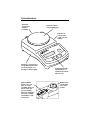
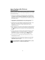
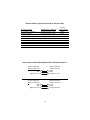
PK-Series
Operation Manual
2 01g
-22000g; d=0.
PK
Max
ozt t
dw
oz
g
o
Mem
RE
T APrint
ry
Off
g
ntin
Cou
On ory
Mem
Cal e
d
Mo
902378.1 Rev. B
You have purchased a quality precision weighing instrument that
requires handling with care.
Read entire contents of this Operation Manual prior to operating
your new Denver Instrument balance.
Disclaimer Notice
Calibrate your balance using a reference weight of the appropriate
tolerance (class). An instrument can be no more accurate than the
standard to which it has been compared. For assistance in the selection of reference weights, please contact the factory.
!
Caution!
Changes or modifications not expressly approved by the manufacturer could void the user’s authority to operate this equipment.
!
Warning
Never lift balance by the weighing pan as this may cause
damage to internal mechanisms.
Always lift and transport the balance by its base, including
removal from packing materials!
Table of Contents
Specifications
ii
Introdcution
1
Getting Started
2
Warnings and Safety Information
2
Operation
3
Calibration
4
Features
5
Keypad Functions
6
Parts Counting
7
The Memory Key and Function
8
RS232 Interface
9
Communication Port Settings
9
User Configurable Balance Parameters
10
Printing to a Printer or Computer
11
Troubleshooting
13
Accessories
14
Warranty Instructions
inside back cover
i
Specifications
Model
Capacity
Readability
Repeatability
Pan Size
PK-202
200g
0.01g
0.01g
4.5” dia. (115mm)
PK-352
350g
0.01g
0.01g
4.5” dia. (115mm)
PK-401
400g
0.1g
0.1g
5.5” x 5.7” (141 x 145mm)
PK-601
600g
0.1g
0.1g
5.5” x 5.7” (141 x 145mm)
PK-1201
1200g
0.1g
0.1g
5.5” x 5.7” (141 x 145mm)
PK-2401
2400g
0.1g
0.1g
5.5” x 5.7” (141 x 145mm)
PK-4801
4800g
0.1g
0.1g
5.5” x 5.7” (141 x 145mm)
PK-4
4000g
1g
1g
5.5” x 5.7” (141 x 145mm)
PK-6
6000g
1g
1g
5.5” x 5.7” (141 x 145mm)
PK-10
10,000
1g
1g
5.5” x 5.7” (141 x 145mm)
Common Specifications:
Dimensions (L x W x H)
Net weight
Power requirements
Operating temperature
Humidity
Calibration
Weighing modes
Programs
Stabilization time
Maximum overload
Tare range
10.3 x 5.8 x 3.5” (260 x 146 x 89mm)
4 lb. (1.8kg)
9V battery or AC adapter
10° - 30°C (50° - 86°F)
Less than 80% RH
automatic, external
g, oz, dwt, ct
counting, formulation
3 seconds
150% of capacity
by subtraction
ii
Introduction
9V battery
operation for
complete
portability
Brushed stainless
steel weighing pan
Built-in lock
down bracket
(cable sold separately)
2 .01g
-22000g; d=0
PK
x
Ma
ozt t
dw
oz
g
Mem
RE
T APrint
or y
Off
Cou
Housing is constructed of
sturdy ABS material with
special structural crossbracing for added rigidity
n
ting
On o r y
m
Me
Cal e
d
Mo
Sealed keypad with
raised buttons for
tactile feel and audio
function tone
Optional RS232
interface for computer or printer
capability. Data output in seven categories including
baud rate, manual or
auto print, stability
and ambient condition presets.
Bubble level
and leveling
feet on all
models
1
Getting Started
• Avoid lengthy exposure to extreme heat or cold. Your balance works
best when operated within the temperature limits listed in the specifications. Always allow the unit to acclimate to a stable temperature before
calibration.
• Allow at least 30 minutes of warm up time before starting weighing operation or calibration to give internal components sufficient time to stabilize.
• Keep your operating environment as clean as possible. Electrostatic
fields, gravitational fields, dust, dirt, moisture, vibration, air currents, and
proximity to other electronic equipment can all have an adverse effect on
the reliability and accuracy of your unit.
• Handle with care. Carefully set weighing pan onto top of unit until level.
Gently apply all items to be weighed onto the center of pan. Although
designed to be quite durable, avoid rough treatment as this may permanently damage the internal sensor.
Warnings and Safety Information
Read all of the Operation Manual prior to attempting to operate your precision balance. Connect only Denver Instrument accessories and options, as
these are designed for optimal performance.
!
Warning!
Make sure that the voltage rating printed on the AC adapter
is identical to your local line voltage.
Do not use this balance in a hazardous location.
The only way to turn power completely off is by disconnecting the
AC adapter from the balance.
Protect the AC adapter from contact with liquids.
!
Warning!
This unit has no user serviceable parts! Do not open the balance housing,
as this will invalidate the manufacturer’s warranty!
2
Operation
AC Adapter Operation
!
CAUTION!
Use only a 9V Adapter with a negative tip, as provided, to supply AC
power. Use of another type of adapter may permanently damage the unit
and will void the warranty.
Insert the female plug into the receptacle at the rear of the unit, and then
into the desired electrical outlet. Check you use of any extension cord
which may affect power output. Unplug AC adapter when not in use for
extended periods.
Battery Operation
1. To install battery, open battery cover on bottom of balance and connect
battery to snap. Place battery into its compartment and replace the
cover. Always handle battery lead wires with care. DO NOT USE
EXCESSIVE FORCE!
2. Remove battery when balance is not used for extended periods.
Replace battery when LCD indicates “LO”.
3
Calibration
Note:
Memo:
IMPORTANT: Only use the calibration weights provided or OIML
Class weights.
Always perform the calibration procedure AFTER the unit has been
allowed to properly warm up (at least 30 minutes). It is also recommended to recalibrate the unit periodically during long periods of use and to
always start a procedure by taring the unit to re-zero the balance.
Calibration is always recommended when first using the balance or after
the unit has been moved or subjected to an extreme change in temperature.
Calibration Procedure
1. After allowing unit to warm for 30 minutes, remove all items from the
pan and tare the balance.
2. After observing a stable “0” with an arrow in the (g) gram mode, press
and hold the CAL/MODE button until calibration weight value appears
on the display.
3. Gently place the correct calibration weight onto the pan.
4. The + sign will disappear. Wait approximately ten seconds as the unit
performs internal calibration.
Note:
Memo:
IMPORTANT - Do not disturb the balance during this time. Avoid
vibration and air currents.
5. When calibration is complete the unit will beep, correct calibration
weight value will disappear for one second then reappear as an active
weight value. The balance is now calibrated.
6. Remove calibration weight and press the TARE button to reset the zero
point.
Note:
Memo:
If calibration weight value remains on the LCD display, an improper calibration weight has been used. Remove improper weight
and repeat calibration procedure with correct weight.
4
Display and Keypad Functions
• Power Up Segment Test: When first turning on the unit, all segments of
the LCD display will appear as shown. This display will remain for
approximately three seconds and then reset to zero.
• Stable Reading Indication: A right-facing arrow appears on the right side
of the display indicating the weighing mode in which the unit is operating. This arrow will disappear during weighing while the unit stabilizes,
and then reappear when a stable value is reached.
• Key Tone: Pressing the ON, TARE and CAL/MODE buttons on the front
panel will emit a tone indicating registry of the function. There is no key
tone with the OFF keypad.
• Overload: When an applied load exceeds the unit’s capacity, “H” will
appear on the display. Remove excessive load immediately.
• Negative Value: Any tared value will be displayed as a negative number
once all weight is removed from the weighing surface. The negative sign
will appear and tared value will be displayed.
• Tare: The tare feature is designed to allow the user to reset the balance
to zero at any time. Tare can also be used to eliminate the value of a pan
liner, scoop, beaker, etc. from a sample or procedure, when the weighed
material needs to be held in a container and only the net weight of the
material is desired.
Place the container only (without material) on the weighing tray, wait for
a stable reading and then press tare. The unit returns to zero and the
weight value of the container is permanently removed from the remainder of the procedure.
When all weight is removed from the weighing tray, the tared value of
the container will be displayed as a negative number. Press the TARE
key again to return the balance to zero.
NOTE: The total weight of the container plus material cannot
exceed the capacity of the balance.
Note:
Memo:
• Auto Off: An auto shut off feature is provided which is operational only while the unit is operating under battery power. The
unit will automatically turn off after approximately two minutes if
no active weighing takes place. Auto shut off will not occur during operation with AC Adapter.
• Lock Down Bracket: A molded piece is attached to the back of the balance housing that can be used on an optional basis to secure the unit. An
optional cable lock can be incorporated and is sold separately as an
accessory.
5
Keypad Functions
Memory
ozt
dwt
oz
g
TARE
Print
Counting
Cal
Mode
On
Memory
Off
• ON/MEMORY: Press to turn on balance. For Memory function operation
refer to Memory Function, page 8.
• OFF: Press to turn off balance.
• CAL/MODE: Press and hold this key to begin calibration procedure as
outlined under the CALIBRATION section. After unit is on or calibrated,
briefly pressing the same key will change the weighing mode. When balance is turned on the unit initially defaults to the gram (g) mode.
However, if the mode is changed the balance will default to the last mode
used when turned on again.
The right facing arrow will point to the weighing mode the unit is currently displaying. To change modes briefly press the CAL/MODE key to
scroll between grams (g), ounces (oz), carats (ct), and penny weights
(dwt).
• TARE/PRINT: Press tare to reset the balance to zero. Tare can be used to
eliminate the weight value of a container from a sample or procedure.
The container weight is permanently removed from the remainder of the
procedure. When all weight is removed from the weighing tray, the tared
value of a container will be displayed as a negative number. Press TARE
again to return the balance to zero.
6
Parts Counting
HOW TO USE THE PARTS COUNTING FEATURE
1. To set your balance to parts counting mode, scroll through the weighing
modes by pressing the CAL/MODE keypad until a down facing arrow
appears in the lower left corner on the display. The minimum parts
quantity number (5) will also be displayed as rEF 5.
2. Continue to press the CAL/MODE key to select the desired parts counting unit: 5, 10, 20, 50 pieces. After “50” is displayed, the indicator will
scroll back to the gram weighing mode.
3. With the selected parts counting unit still displayed, place the desired
sample on the weigh pan. Allow the sample to stabilize for 3-5 seconds
then press TARE. The parts counting function is now set for the selected
5, 10, 20, 50 piece quantity and you can start the counting procedure.
IMPORTANT: Minimum individual (1 piece) part weight must be greater
than or equal to 2X “D” (“d” is the division or graduation of the balance).
If the sample unit weight for one piece is less than 2X “D” the display will
read “E 22”, indicating that the individual (1 piece) part weight is too low
and must be increased.
To reset, press CAL/MODE and scroll through the weighing modes again to
the desired parts counting value. Refer to the following chart for minimum
unit part weight (1 piece) for your particular balance.
Balance Graduation
1 gram
0.1 gram
0.01 gram
Minimum (1 piece) Part Weight
2 grams
0.2 gram
0.02 gram
7
Memory Function
All PK-Series balances include a unique memory function that allows
cumulative weighing up to the capacity of the balance. Using the memory
function requires the following steps:
1. After making sure that the balance is on, start by pressing the
“TARE/PRINT” key to tare the balance out to zero.
2. Place a sample on the pan, and when the displayed weight is stable,
briefly press the “ON/MEMORY” key. An arrow appears on the upper
left side of the display. This action adds the displayed weight value to
the value contained in memory buffer, which is initially set to zero, and
re-tares the balance so the LCD once again reads “0” (zero).
3. Repeat #2, above, as many times as you want until you are ready to see
the cumulative weight of all samples weighed.
4. To view the cumulative weight, press and hold the “ON/MEMORY” key
until a beep is heard. When the beep sounds, the memory buffer is
dumped to the LCD and the total sum of everything weighed is visible.
This also clears out the memory buffer and re-initializes it to zero.
5. Briefly press “TARE/PRINT” key in order to tare out the balance, and you
are ready to proceed with normal weighing operation..
Note:
Memo:
Note:
Memo:
If you begin using the memory function, and decide that you do
not need to do cumulative weighing at the moment, perform #4 &
5 above to jump out of the memory function mode.
You cannot switch weighing modes after beginning to use the
memory function. If you want to do cumulative weighing using a
different weighing mode, like pennyweight (dwt), switch to that
weighing mode first, before invoking the memory function.
8
RS232C Interface
PK-Series balances are equipped with a standard 9-pin male, bi-directional
RS-232 interface located at the rear of the balance. The RS-232 communication parameters are configurable with respect to baud rate, parity, # of
stop bits, and handshake. A seven-bit ASCII data stream is sent from the
balance to an appropriate connected computer or printer via the proper
data interface cable. Correctly configured cables can be purchased from
Denver Instrument, or, can be made by the user. See the table “Data
Interface Cable PIN Configuration For PK-Series Balances”.
Communication Port Settings
User Configurable Internal Menu Codes
Category
Ambient Conditions
Stability Range
External CAL Units
External Calibration
Auto Zero
Baud Rate
Parity 5
Stop Bits
Handshake
Print Stream
Printed Output
Menu Codes Reset
Segment Position
L
C
R
1
1
1
1
1
2*
1
1
3
1
1
4
1
3
1
1
3
2
1
3
3
1
3
4*
1
3
5
1
4
1*
1
5
1*
1
5
2
1
6
1*
1
6
2
5
1
1
5
1
2
5
1
3
5
1
4*
5
1
5
5
1
6
5
1
7
2
1
mark
5
2
2
5
2
3*
5
2
4
5
3
1*
5
3
2
5
4
1
5
4
2
5
4
3*
6
1
1
6
1
2*
6
1
3
6
1
4
7
1
1*
7
1
2
9
1
1
Value
very stable
stable (default)
unstable
very unstable
⁄ digit
fi digit
1 digit
2 digits
4 digits
grams (default)
external calibration is enabled (default)
external calibration is disabled
on (default)
off
150
300
600
1200 (default)
2400
4800
9600
space
odd (default)
even
1 stop bit (default)
2 stop bits
software
hardware, w/2 chars after CTS (default)
hardware, w/1 char after CTS
manual print, regardless of stability
manual print when stable (default)
continuous print, regardless of stability
continuous print, when stable
LCD contents only (default)
header and LCD contents
reset balance to factory defaults
Note: Settings 5--, 6-- and 7-- have no effect on VI-Series balances because they affect performance of the RS-232 port included with VIR-Series balances only.
*=Factory default setting.
9
User Configurable Balance
Parameters
Changing configurable internal balance parameters requires accessing the
balance internal menu system via the keypad. Navigating the menu system
is performed as follows:
1. To gain access to the balance internal menu system, start with the balance turned off. Briefly press the "ON/MEMORY" key and immediately
(and briefly) press the "TARE/PRINT" key while all LCD segments are illuminated. You should see a "1" toward the left side of the LCD. This is the
"left" segment value.
2. To increment the displayed digit within any segment, briefly press the
"TARE/PRINT" key repeatedly until you reach your target value.
3. To switch from one code segment to another, IE. from the left to center
digit, center to right digit, or right to left digit, briefly press the
"CAL/MODE" key. Increment each digit segment by the method
explained in #2, above.
4. When switching from the center to right segment, the number displayed
is the setting that is currently selected - marked by a small right facing
arrow
that points to the “g” indicator on the lower right side of the
display.
5. To select a new value, increment the third segment (#2) until you reach
the new desired value. To lock in this new value, press and hold the
"CAL/MODE" key until the small right facing arrow
appears and
points to the “g” indicator on the lower right side of the display.
6. If you need to move on and change other internal values, do so by
repeating steps 2-5 above.
7. To finalize and save all revised parameter settings, press and hold the
"TARE/PRINT" key until the balance resets. All your new settings are
now balance defaults at startup.
Note:
Memo:
To reset the balance to all its factory default parameters, specify
the menu code "9 - 1" and invoke step #7, above.
10
Printing to a Printer or Computer
Printing with PK-Series balances simply means that the displayed LCD contents are sent out the 9-pin RS-232 port to either a connected printer or
computer. To successfully print the following conditions must exist:
1. Attach the balance to a printer or computer using the appropriate data
interface cable. The correct cable must be used to connect the two
devices together. Correctly configured cables can be purchased from
Denver Instrument, or, can be made by the user. See the table “Data
Interface Cable PIN Configuration For PK-Series Balances”.
2. The RS-232 settings on both the balance and printer (or computer) must
be the same. Both devices must be set to the same number of data bits
(“7”, not configurable), baud rate, parity, stop bits and handshake.
3. If the balance is set to manual print (default), press and hold the
“TARE/PRINT” key until an audible beep is heard. The LCD contents will
be sent out the RS-232 port to the attached device.
Controlling The Balance Remotely Via Computer
Because the PK-Series RS-232 interface is bi-directional, a connected computer can remotely control the balance. There are nine (9) balance functions, as listed in the table entitled “Remote Balance Operation Functions
& Control Codes” that can be remotely invoked from an attached computer. The process of sending these codes varies depending on the computer
software used. Programming languages such as C++ and Visual Basic can
be used to create routines to grab data from the balance. There are also
many software packages commercially available to help users capture data
from RS-232-enabled laboratory devices, like the PK-Series.
11
Remote Balance Operation Functions & Control Codes
Remote Function
Very Stable Conditions
Stable Conditions
Unstable Conditions
Very Unstable Conditions
Disable Balance Keypad
Enable Balance Keypad
Print When Stable
Tare
Invoke External Calibration
How Balance is Affected
Changes balance state
Changes balance state
Changes balance state
Changes balance state
Changes balance state
Changes balance state
Performs a function
Performs a function
Performs a function
PC Key
Control Codes
ESC K
ESC L
ESC M
ESC N
ESC O
ESC R
ESC P
ESC T
ESC W
Data Interface Cable PIN Configuration For PK-Series Balances
Denver PK-Series
Balance 9-PIN port
RxD 2
TxD 3
Signal Ground 5
Standard RS-232
9-PIN Connector
3 TxD
2 RxD
5 Signal Ground
Denver PK-Series
Balance 9-PIN port
RxD 2
TxD 3
Signal Ground 5
Standard RS-232
25-PIN Connector
2 TxD
3 RxD
7 Signal Ground
12
Troubleshooting
Display Shows:
Cause:
Remedy:
No segments appear
on the display.
I/O key pressed
Press the I/O key.
to turn OFF Display.
L
The balance is
underloaded.
Check the weighing pan
for proper installation.
Weight is too light or there
is no sample on balance.
Increase reference
quantity.
The load exceeds the
balance capacity.
Unload the balance or
look for obstruction.
Display capacity
is exceeded.
Decrease weight
on balance.
LO
E -02
Low battery.
Replace battery.
The calibration operation
is being attempted and
vibration, air drafts or
other unstable conditions
exist.
Place balance in a
stable environment
before calibrating.
Before pushing the
CAL/MODE button, the
LCD should display a stable
ZERO with the arrow mode.
E -10
There is a value stored
in the memory when the
TARE button is pressed.
Clear the memory or
turn the balance off to
restore normal tare function.
E -30
An electronic malfunction
has occurred.
Contact Denver Instrument
E-54
This indicates the
electronics are no longer
within the factory set
parameters. Objects have
dropped onto the weighing
pan or the balance itself
has been dropped.
Contact Denver Instrument
▲
The sensor is out of
specification. The balance
has been damaged by
rough handling. Liquids or
other materials have spilled
into the balance.
Contact Denver Instrument
H
Note:
Memo:
Do not attempt to access internal components or make any unauthorized repairs since this will void the warranty.
13
Accessories
Supplied Accessories
AC Adapter (DC 12V)
For use in USA/Canada (AC 120V 60Hz)
For use in U.K. (AC 240V 50Hz)
For use in AUS/NZ (AC 240V 50Hz)
For use in Europe (AC 240V 50Hz)
For use in Japan (AC 100V 50/60Hz)
400000.1
400082.1
400084.1
400081.1
400083.1
Calibration Weights
PK-202 (1), PK-352 (1) 200g, Class M1
PK-401 (1), PK-601 (2) 200g, Class M2
400218.1
400073.1
Optional Accessories
Cable lock
Carrying case
Glass Draft Ring with stainless steel cover and
stainless steel spill ring
14
400171.1
400219.1
400289.1
Warranty Instructions
1. Please return the prepaid, pre-addressed Purchase Registration Card to
Denver Instrument Company promptly upon your purchase of the
Denver Instrument product. The return of the card is not a condition
precedent to warranty coverage.
2. If you have any questions about a Denver Instrument product, please
contact the nearest Denver Instrument office as listed below.
3. If it becomes necessary to return your Denver Instrument product for
service, you must obtain a “Return Authorization Number”. Please pack
the product securely in its original approved packing carton or an other
suitable container. Include your Return Authorization Number on the
shipping label. Shipping charges must be fully prepaid.
Return to authorized distributor or :
North and South America:
Denver Instrument Company
6542 Fig Street
Arvada, Colorado 80004
1-800-321-1135
Tel: 303-431-7255
Fax: 303-423-4831
U.K. and Ireland:
Denver Instrument Company
Denver House, Sovereign Way
Trafalgar Business Park
Downham Market
Norfolk PE38 9SW England
Tel: 44 136 63862 42
Fax: 44 136 63862 04
Europe, Asia and Australia:
Denver Instrument GmbH
Robert-Bosch-Briete 10
37079 Gottingen Germany
Tel: 49 551 20977 31
Fax: 49 551 20977 39
15
Certificate
of Calibration
We hereby certify that this instrument
was manufactured in the United States
and that it has been calibrated using appropriate reference standards traceable to the
National Institute of Standards
and Technology.
This instrument has been fully
inspected and has passed all quality tests as
specified by
Denver Instrument Company
quality procedures.
To assure proper measurements, it is
necessary to periodically recalibrate the
instrument using appropriate standards
as specified in the operating manual.
North and South America:
Denver Instrument Company
6542 Fig Street
Arvada, Colorado 80004
1-800-321-1135
Tel: 303-431-7255
Fax: 303-423-4831
U.K. and Ireland:
Denver Instrument Company
Denver House, Sovereign Way
Trafalgar Business Park
Downham Market
Norfolk PE38 9SW England
Tel: 44 136 63862 42
Fax: 44 136 63862 04
Europe, Asia and Australia:
Denver Instrument GmbH
Robert-Bosch-Briete 10
37079 Gottingen Germany
Tel: 49 551 20977 31
Fax: 49 551 20977 39
www.denverinstrument.com