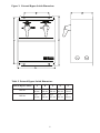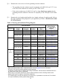
1
UNITY/I
TM
UT3K, UT4K, UT5K and UT8K
Single-Phase Uninterruptible Power Systems
Installation Manual
MLS-0351C-OL
Copyright 1994-1997 Best Power. All rights reserved.
å
IMPORTANT SAFETY INSTRUCTIONS!
SAVE THESE INSTRUCTIONS!
This manual contains important instructions for your UNITY/I™ UPS.
The installation and use of this product must comply with all national, federal, state, municipal, or local
codes that apply.
If you need help, phone Best Power’s Worldwide Service at 1-800-356-5737 (U.S.A. or Canada) or
call the nearest Best Power office. Customers anywhere can call 1-608-565-2100 to reach Best Power’s
Worldwide Service.
CAUTION!
FOR UNITS WITH HARDWIRED OUTPUT:
The output AC circuit is considered a separately derived source. A QUALIFIED ELECTRICIAN
MUST PROPERLY CONNECT THE NEUTRAL-TO-GROUND (NEUTRAL-TO-EARTH)
WIRE BEFORE INSTALLING THE UPS. This installation manual contains instructions for
properly grounding the circuit. Refer to the installation wiring diagrams for your application.
Best Power reserves the right to change specifications without prior notice.
å
Who needs to use this installation manual?
This manual contains instructions for the installation of hardwired units (units that do not
have an input line cord or output receptacles).
The installation and wiring instructions in this manual are for use by
a qualified electrician only.
Who does not need to use this installation manual?
If your UNITY/I has all of the following, you do not need to use the installation instructions
in this manual, though you may find Sections 102 and 103 helpful in finding a location for
your UPS.
• an input line cord and plug
• receptacles on the back panel
The UNITY/I User Manual explains how to plug in and start your UPS.
August 8, 1997
å
Contents
Introduction . . . . . . . . . . . . . . . . . . . . . . . . . . . . . . . . . . . . . . . . . . . . . . . . . . . . . . . . . . . . . . .1
Section 100 Before Installing the UPS . . . . . . . . . . . . . . . . . . . . . . . . . . . . . . . . . . . . . .2
101 Pre-Installation Check . . . . . . . . . . . . . . . . . . . . . . . . . . . . . . . . . . . . . . . . . . . . . . . . .2
102 Equipment Dimensions . . . . . . . . . . . . . . . . . . . . . . . . . . . . . . . . . . . . . . . . . . . . . . . . .4
103 Finding a Location for the UPS . . . . . . . . . . . . . . . . . . . . . . . . . . . . . . . . . . . . . . . . . .6
Section 200 Starting the AC Installation . . . . . . . . . . . . . . . . . . . . . . . . . . . . . . . . . . . .8
201 Positioning the Equipment . . . . . . . . . . . . . . . . . . . . . . . . . . . . . . . . . . . . . . . . . . . . . .8
202 Sizing the Overcurrent Protection Devices and Wires . . . . . . . . . . . . . . . . . . . . . . . . . .8
Section 300 AC Installation . . . . . . . . . . . . . . . . . . . . . . . . . . . . . . . . . . . . . . . . . . . . .11
301 Removing the Covers and Knock Outs . . . . . . . . . . . . . . . . . . . . . . . . . . . . . . . . . . . .11
302 Installing the Conduit and Wiring . . . . . . . . . . . . . . . . . . . . . . . . . . . . . . . . . . . . . . . .12
303 Installing the Overcurrent Protection Devices . . . . . . . . . . . . . . . . . . . . . . . . . . . . . . .24
304 Voltage and Phase Check . . . . . . . . . . . . . . . . . . . . . . . . . . . . . . . . . . . . . . . . . . . . . .25
Section 400 Additional Requirements . . . . . . . . . . . . . . . . . . . . . . . . . . . . . . . . . . . . .28
Appendix: External Bypass Switches . . . . . . . . . . . . . . . . . . . . . . . . . . . . . . . . . . . . . .29
Tables and Figures
Tables
Table 1 UNITY/I Frequency, Voltage, and Bypass Switch Combinations . . . . . . . . . . . . . . . . .3
Table 2 Best Power External Bypass Switch Ratings and Applications . . . . . . . . . . . . . . . . . . .3
Table 3 UPS Dimensions . . . . . . . . . . . . . . . . . . . . . . . . . . . . . . . . . . . . . . . . . . . . . . . . . . . . .4
Table 4 Battery Cabinet Dimensions . . . . . . . . . . . . . . . . . . . . . . . . . . . . . . . . . . . . . . . . . . . .4
Table 5 External Bypass Switch Dimensions . . . . . . . . . . . . . . . . . . . . . . . . . . . . . . . . . . . . . .5
Table 6 Recommended Input Circuit Breaker . . . . . . . . . . . . . . . . . . . . . . . . . . . . . . . . . . . . . .8
Table 7 Maximum Permitted UPS Output Overcurrent Protection Device Rating . . . . . . . . . . .9
Table 8 Minimum Recommended Wire Sizes . . . . . . . . . . . . . . . . . . . . . . . . . . . . . . . . . . . . . .9
Table 9 Choosing an Installation Wiring Diagram . . . . . . . . . . . . . . . . . . . . . . . . . . . . . . . . .10
Table 10 Recommended Input Fuse for Models with Optional 380/400/415 VAC Input . . . . .21
Table 11 Maximum Output Current per Phase (Leg) . . . . . . . . . . . . . . . . . . . . . . . . . . . . . . . .25
Table 12 Output Voltage Reference Settings . . . . . . . . . . . . . . . . . . . . . . . . . . . . . . . . . . . . . .26
Table 13 External Bypass Switch Positions . . . . . . . . . . . . . . . . . . . . . . . . . . . . . . . . . . . . . .29
Figures
Figure 1 UPS Dimensions . . . . . . . . . . . . . . . . . . . . . . . . . . . . . . . . . . . . . . . . . . . . . . . . . . . .4
Figure 2 Battery Cabinet . . . . . . . . . . . . . . . . . . . . . . . . . . . . . . . . . . . . . . . . . . . . . . . . . . . . .4
Figure 3 External Bypass Switch Dimensions . . . . . . . . . . . . . . . . . . . . . . . . . . . . . . . . . . . . .5
Figure 4 Typical Hardwired UPS Installation . . . . . . . . . . . . . . . . . . . . . . . . . . . . . . . . . . . . . .6
Figure 5 Wiring Diagram for UT3K, UT4K, UT5K and UT8K UPS
with External Bypass Switch (L1, L2, N) . . . . . . . . . . . . . . . . . . . . . . . . . . . . . . . . . . .14
Figure 6 Wiring Diagram for UT3K, UT4K, UT5K and UT8K UPS
with External Bypass Switch and External Input Isolation Transformer . . . . . . . . . . . .16
Figure 7 Wiring Diagram for UT3K, UT4K, UT5K and UT8K UPS
with External Bypass Switch (L - N High Voltage Only) . . . . . . . . . . . . . . . . . . . . . . .18
Figure 8 Wiring Diagram for UT3K, UT4K, UT5K and UT8K UPS
with Optional 380/400/415 VAC Input . . . . . . . . . . . . . . . . . . . . . . . . . . . . . . . . . . . . .20
Figure 9 UPS Output Wiring Connections . . . . . . . . . . . . . . . . . . . . . . . . . . . . . . . . . . . . . . .22 - 24
Figure 10 Remote Emergency Power Off (EPO) Switch . . . . . . . . . . . . . . . . . . . . . . . . . . . . .28
Figure 11 Service Panel Warning Label . . . . . . . . . . . . . . . . . . . . . . . . . . . . . . . . . . . . . . . . .28
Introduction
This UNITY/ITM Installation Manual is for models that do not have an input plug. A qualified electrician must install the AC wiring for these models.
The end-user may wish to read this manual, especially Section 100 and the Appendix. However, a
qualified electrician must install hardwired units.
In the step-by-step instructions, boxes ❑ are provided so that the electrician can check off each step as
it is completed.
If you have any questions about the installation or operation of the UPS, call Best Power’s Worldwide
Service at 1-800-356-5737 (U.S.A. or Canada) or call the nearest Best Power office. Customers
anywhere can call 1-608-565-2100 to reach Best Power’s Worldwide Service.
1
Section 100: Before Installing the UPS
101
Pre-Installation Check
Find the following information. Use the labels on the equipment.
UPS:
• kW rating (see UPS model #):
• AC volts in (range):
•
•
AC volts out (range):
Frequency:
Load equipment:
• Combined kW rating:
• AC voltage(s):
• Frequency:
__________ kW
❑ 200 - 240 VAC (standard)
❑ 380 - 415 VAC (optional)
100 - 127 VAC, 200 - 240 VAC (all models)
50/60 Hz. On line, input frequency is the same as output
frequency.
__________ kW
__________ VAC and __________ VAC
__________ Hz
Utility service available on site (AC input to UPS):
• Voltage provided to UPS:
__________ VAC
• Frequency:
__________ Hz
External bypass switch (optional):
• Best Power model number:
• Break-Before-Make (BBM) or
Make-Before-Break (MBB)?
_____________
❑ BBM
❑ MBB
❑ 1. Verify that the total kW rating of the load equipment does not exceed the kW rating of the UPS.
❑ 2. Verify that the service panel will supply the proper voltage to the UPS.
NOTE:
480 VAC service may be used if the proper step-down transformer is placed between
the service panel and the UPS. See Table 1, note 4.
❑ 3. Find your frequency, UPS input voltage, and UPS output voltage combination in Table 1. Call
Best Power if you do not find your application in the table.
❑ 4. Use Table 1 and Table 2 to verify that you have the correct model and type of bypass switch.
❑ 5. Verify that the frequency supplied at the service panel (UPS input) matches the frequency
required by the loads.
2
Table 1: UNITY/I Frequency, Voltage, and Bypass Switch Combinations
Frequency
UPS Input
Voltage
UPS Output Voltage(s)
to Load Equipment
External Bypass
Switch Type1
50 Hz
380, 400, or 4152
220, 230, or 240
BBM only
220
127/2203
BBM only
127
BBM only
208 or 480 V source
240 V input
120 and/or 240
BBM or MBB
200
100 and/or 200
BBM or MBB
220
110 and/or 220
BBM or MBB
230
115 and/or 230
BBM or MBB
208
208
BBM only
208
120/2083, 5
BBM only
208
120 and/or 240
BBM only
240
208
BBM only
240
120/2083, 5
BBM only
240
120 and/or 240
BBM or MBB
220
60 Hz
4
50 Hz
or 60 Hz
1
2
3
4
5
BBM = Break-Before-Make, MBB = Make-Before-Break. See the Appendix for more information.
380, 400 or 415 volt input requires optional internal transformer.
To install 127/220 out or 120/208 out, call Best Power’s Worldwide Service or the nearest Best Power office for
assistance.
With a step-up or step-down transformer. Use an isolation transformer with a 120/240 grounded center-tapped
neutral output. Do not use a buck/boost transformer.
For 120/208 output, if the 208 volt loads can run at 240 volts, it is preferable to use 240 volts. The 120/240 volt
output combination provides greater loading flexibility.
Table 2: Best Power External Bypass Switch Ratings and Applications
Bypass
Model
Number
Used with
UPS
Model(s)...
Maximum
Operating
Voltage
Amps
Amps
Continuous Continuous
(UL/cUL)
(TÜV)
BPE-02
UT3K,
UT4K, UT5K
300
40
BPE-04
UT3K, UT4K,
UT5K, UT8K
300
80
3
Maximum
Amps
Frequency
Weight
(lbs/kg)
50
50
50/60 Hz
19.75/9
80
100
50/60 Hz
30/13.6
102 Equipment Dimensions
Figure 1: UPS Dimensions
B
Table 3: UPS Dimensions
C
UPS
Model
Height
(A)
Width
(B)
Depth
(C)
UT3K
UT4K
UT5K
29 in.
737 mm
10.5 in.
267 mm
25.75 in.*
654 mm*
UT8K
31.5 in.
800 mm
12.75 in.
374 mm
32.5 in.*
826 mm*
*If the UPS has an external battery cabinet,
add the depth of the battery connection box.
For the 3K, 4K, and 5K, add 2.75 in. (70 mm);
for the 8K, add 3.25 in. (83 mm).
A
Required Clearances:
Ventilation: 4 in. (102 mm) at the rear and top.
Service:
36 in. (910 mm) at the front.
Best Power recommends an additional service
clearance of 36 in. (910 mm) at each side.
Table 4: Battery Cabinet Dimensions
Model
Height
Width
Depth
EBPUT1
EBPUT2
EBP1W
EBP2W
EBP3W
29 in.
737 mm
10.5 in.
267 mm
25.75 in.
654 mm
EBPUT6
EBPUT7
EBPUT21
EBPUT22
31.5 in.
800 mm
12.75 in.
324 mm
32.5 in.
826 mm
Figure 2: Battery Cabinet
Required Clearances:
Ventilation: 4 in. (102 mm) at the rear and top.
Service:
36 in. (910 mm) at the front.
Best Power recommends an additional service
clearance of 36 in. (910 mm) on the right side.
4
Figure 3: External Bypass Switch Dimensions
Table 5: External Bypass Switch Dimensions
External Bypass Switch
A
B
C
D
E
BPE-02
16 in.
406 mm
8 in.
203 mm
17 in.
432 mm
12 in.
305 mm
7 in.
178 mm
BPE-04
17 in.
432 mm
12 in.
305 mm
18 in.
457 mm
16 in.
406 mm
9 in.
229 mm
5
103
Finding a Location for the UPS
Figure 4 shows an overview of a typical installation for a hardwired UPS.
Figure 4: Typical Hardwired UPS Installation
❑ 1.
❑ 2.
Survey the site and locate the following:
•
Input service panel. The installing electrician should install the UPS on a dedicated circuit.
•
Load panel (if desired).
•
Load equipment.
Find an appropriate location for the UPS (and external bypass switch and battery cabinet, if
applicable). Keep the following guidelines in mind.
•
Locate the UPS as close as possible to the load panel and loads. If there is more than 25 feet
(7.6 m) of wiring between the UPS and the loads, noise and spikes can reappear in the electrical distribution system.
•
See Section 102 for equipment dimensions.
6
•
•
Provide proper UPS ventilation clearance and service clearance.
•
Required ventilation clearance: 4 inches (100 mm) at the rear and top.
•
Required service clearance: 36 inches (910 mm) at the front.
•
Recommended additional service clearance: 36 inches (910 mm) at each side,
especially the left.
Place the UPS in the proper environment.
•
Ambient temperature: 0° to 40° C (32° to 104° F). Battery life is longer if the temperature stays below 25° C (77° F).
•
Relative humidity: 0 to 95%.
•
Maximum elevation: 10,000 feet (3050 meters). Operating temperature drops 1° C
per 1000 feet (305 meters) above sea level.
•
Ventilation: Air must be clean, dust-free, and free of corrosive chemicals and other
contaminants. Air must be free to circulate around the UPS. Do not place the UPS in
a sealed room or container.
•
The external bypass switch must be mounted within sight of the UPS.
•
The external battery pack(s) should be as close as possible to the UPS. See the information
that came with your external battery pack(s).
7
Section 200: Starting the AC Installation
The UPS must be installed by a qualified electrician.
201
Positioning the Equipment
❑ 1.
Put the UPS in place. Follow the guidelines in Section 103.
❑ 2.
If applicable, mount the external bypass switch within sight of the UPS.
❑ 3.
An AC disconnect device must be located within sight of the UPS. The AC disconnect device
should be one of the following:
202
•
An external bypass switch with an AC disconnect switch.
•
A separate AC disconnect switch.
•
The incoming AC line fuse box or panel, if located within sight of the UPS.
Sizing the Overcurrent Protection Devices and Wires
❑ 1.
Table 6 provides the input current and the recommended U.S. circuit breaker size for each
model, battery charger, and input voltage. Outside of the U.S., size the UPS input circuit breaker according to local codes. If you might add the optional 15 amp battery charger in the future,
you may wish to size the input circuit breaker and the wires accordingly now.
NOTE:
If you are installing a 120/208 or 127/220 output voltage combination, call Best
Power’s Worldwide Service or the nearest Best Power office for instructions on sizing the input circuit breaker.
Table 6: Recommended Input Circuit Breaker*
200V
208V
220V
Circuit
Breaker
Input
Circuit
Current Breaker
Input
Circuit
Current Breaker
Input
Circuit
Input
Circuit
Current Breaker Current Breaker
Standard 17 amps
25-amp
17 amps
25-amp
16 amps
20-amp
15 amps
20-amp 14 amps 20-amp
UT3K/15C 15 amp 21 amps
30-amp
21 amps
30-amp
20 amps
25-amp
19 amps
25-amp 18 amps 25-amp
Standard 22 amps
30-amp
22 amps
30-amp
20 amps
25-amp
20 amps
25-amp 19 amps 25-amp
UT4K/15C 15 amp 27 amps
35-amp
26 amps
35-amp
24 amps
30-amp
23 amps
30-amp 22 amps 30-amp
Standard 28 amps
35-amp
27 amps
35-amp
25 amps
35-amp
24 amps
30-amp 23 amps 30-amp
UT5K/15C 15 amp 32 amps
40-amp
31 amps
40-amp
29 amps
40-amp
28 amps
35-amp 27 amps 35-amp
Standard 45 amps
60-amp
43 amps
60-amp
41 amps
60-amp
39 amps
50-amp 38 amps 50-amp
UT8K/15C 15 amp 49 amps
70-amp
47 amps
60-amp
45 amps
60-amp
43 amps
60-amp 41 amps 60-amp
UPS
Model
Battery
Charger
Input
Current
UT3K
UT4K
UT5K
UT8K
* For optional 380/400/415 VAC input, see Table 10 on page 21.
8
230V
240V
❑ 2.
Size the UPS output overcurrent protection device (fuse or circuit breaker) per local code
requirements. Do not exceed the ratings in Table 7. See Table 11 on page 25 for UPS output
current ratings. The table below shows the maximum permitted overcurrent protection device
ratings; these are also the ratings recommended for U.S. applications.
Table 7: Maximum* Permitted UPS Output Overcurrent Protection Device Rating
Maximum Overcurrent Protection Device Rating per Phase (Leg)
Nominal UPS
Output Voltage(s)
UT3K
UT4K
UT5K
UT8K
100 and/or 200
20 A
25 A
35 A
50 A
110 and/or 220
20 A
25 A
30 A
45 A
115 and/or 230
20 A
25 A
30 A
45 A
120 and/or 240
20 A
25 A
30 A
45 A
127 only
15 A
20 A
25 A
40 A
208 only
20 A
25 A
30 A
50 A
127/220
Call Best Power’s Worldwide Service or the nearest Best Power office.
120/208
* Refer to Table 11 on page 25 for UPS output current ratings and size the UPS output fuse or circuit breaker per local code requirements. Do not exceed the ratings listed in Table 7.
❑ 3.
Size the circuit conductors.
•
Table 8 lists the AWG and mm2 wire size for each input circuit breaker shown in Table 6.
The conductor size shall be no smaller than the 75° C wire size based on the ampacities
given in Table 310-16 of the NEC, ANSI/NFPA 70-1993, and article 220.
•
All circuit conductors, including the neutral and equipment grounding (earth) conductors,
must be the same size (ampacity) wire. Code may require a larger wire size than shown
in Table 8 because of temperature, number of conductors in the conduit, or long service runs. Follow local code requirements.
Table 8: Minimum Recommended Wire Sizes
...use this size 75º C Copper Wire
For this input circuit breaker size (amps)...
AWG
mm2
15, 20
12
3.31
25, 30
10
5.26
35, 40, 45, 50
8
8.36
60
6
13.30
70
4
21.15
9
❑ 4.
❑ 5.
Determine the correct wire size for the grounding electrode conductor.
•
The grounding electrode conductor must be a minimum of #8 AWG (8.36 mm2) 75º C wire,
even if the circuit conductors are smaller, per NEC Table 250-94.
•
If the circuit conductors are #8 AWG (8.36 mm2) or larger, Best Power requires that the
grounding electrode conductor be the same size (ampacity) as the UPS input circuit conductors.
Determine the wire lengths needed and the sizes, lengths, and types of conduit needed. Refer to
the proper installation wiring diagram for your application (see Table 9). Read the notes under
the wiring diagram.
Table 9: Choosing an Installation Wiring Diagram
UPS Input
Voltage
220
UPS Output
Voltage(s)
220
Output
Wires
L-N
Bypass
Type1
BBM or MBB
..Use this Installation
Wiring Diagram
(and Output Wiring
Diagram)
Figure 7 (Figure 9K)
220
110/220
L1, L2, N
BBM or MBB
Figure 5 (Figure 9G)
240
240
L-N
BBM or MBB
Figure 7 (Figure 9M)
L-N
BBM only
Figure 8 (Figure 9K,
9L, or 9M)
If you have these...
Frequency
50 Hz
380, 400, or 4152 220, 230, or 240
60 Hz
50 Hz
or
60 Hz
220
127
L1, L2, N
BBM only
Figure 5 (Figure 9F)
220
127/2203
L1, L2, N
BBM only
Call Best Power.
220
220 (Mexico)
L1, L2, N
BBM only
Figure 5 (Figure 9D)
220
110/220
L1, L2, N
BBM or MBB
Figure 5 (Figure 9E)
220
220
L-N
BBM or MBB
Figure 7 (Figure 9J)
208 or 480
source4, 240 input
120/240
L1, L2, N
BBM or MBB
Figure 6 (Figure 9A)
200
200
L-N
BBM or MBB
Figure 7 (Figure 9I)
200
100/200
L1, L2, N
BBM or MBB
Figure 5 (Figure 9C)
208
208
L1, L2, N
BBM only
Figure 5 (Figure 9B)
L1, L2, N
BBM only
Call Best Power.
208
1
2
3
4
5
120/208
3, 5
208
120/240
L1, L2, N
BBM only
Figure 5 (Figure 9A)
230
230
L-N
BBM or MBB
Figure 7 (Figure 9L)
230
115/230
L1, L2, N
BBM or MBB
Figure 5 (Figure 9H)
240
208
L1, L2, N
BBM only
Figure 5 (Figure 9B)
240
120/2083, 5
L1, L2, N
BBM only
Call Best Power.
240
120/240
L1, L2, N
BBM or MBB
Figure 5 (Figure 9A)
BBM = Break-Before-Make, MBB = Make-Before-Break. See the Appendix for more information.
380, 400 or 415 volt input requires optional internal transformer.
To install the 127/220 output or 120/208 output voltage combination, call Best Power’s Worldwide Service or
the nearest Best Power office for assistance.
With a step-up or step-down transformer. Use an isolation transformer with a 120/240 grounded centertapped neutral output. Do not use a buck/boost transformer.
For 120/208 output, if the 208 volt loads can run at 240 volts, it is preferable to use 240 volts. The 120/240
volt output combination provides greater loading flexibility.
10
Section 300: AC Installation
The UPS must be installed by a qualified electrician.
CAUTION!
A. All UPS units contain hazardous AC and DC voltages. Because of these voltages, a qualified
electrician must install the UPS and AC line service. The electrician must install AC line
according to local and national codes.
B. Before installing, maintaining, or servicing the UPS, always remove or shut off all sources of
AC and DC power and shut off the UPS. Disconnect AC line input at the service panel, turn the
main DC switch on the battery pack(s) to “OFF” (if you have external batteries), and turn the
UPS key switch to “OFF” to make sure it will not supply output voltage.
C. Whenever AC and/or DC voltage is applied, there will be AC voltage at the UPS terminals. The
UPS can supply power from AC line or from its batteries. To avoid equipment damage or
personal injury, always assume that there may be voltage at the UPS terminals.
D. Before you install the external bypass switch, make sure that both the UPS Bypass Switch and
the AC Line Disconnect Switch are turned to “OFF.”
E. To reduce the risk of fire or electric shock, install the UPS and the batteries in a temperature-controlled and humidity-controlled indoor area free of conductive contaminants. See Section 103 for
operating environment specifications.
301
Removing the Covers and Knock Outs
CAUTION!
To prevent electrical shock or damage to your equipment, make sure the key switch inside the front
door of the UPS is “OFF” before you remove the UPS cover. The circuit breaker or AC disconnect
switch must be turned off at the AC input service panel.
❑ 1.
Remove the UPS side covers. To do this, remove the seven screws at the sides and top of the
UPS. Then, lift each cover straight up and off.
❑ 2.
At the UPS back panel, remove knock outs for AC Input and AC Output.
❑ 3.
Remove the lower cover from the external bypass switch (if applicable).
❑ 4.
At the external bypass switch, remove knock outs for AC Line Input, AC to UPS Input, AC
from UPS Output, and AC to Loads.
11
302
Installing the Conduit and Wiring
❑ 1.
Install the conduit and conduit adapters. Refer to the proper installation wiring diagram for your
application (see Table 9, page 10). Read the notes under the wiring diagram.
•
The AC Line Input and AC Line Output conductors must be run through separate
conduits.
•
All UPS output circuits must be installed in dedicated conduit systems and not shared with
other electrical circuits.
CAUTION!
Before installing the external bypass switch, make sure that the UPS Bypass Switch and the UPS
AC Line Disconnect Switch are both in the “OFF” position.
❑ 2.
Make all of the terminal connections inside the external bypass switch (if applicable).
•
Refer to the label on the back of the bypass switch’s lower cover.
•
Refer to the proper installation wiring diagram for your application (see Table 9, page 10).
•
Tighten all connections securely.
CAUTION!
Make sure that the keyswitch inside the front door of the UPS is in the “OFF” position.
Make sure that all sources of AC power are shut off (including AC power to the load distribution panel, if
applicable).
❑ 3.
At the UPS terminal strip, connect the neutral-to-ground (neutral-to-earth)
wire to the proper output terminal before making any other connections to
the UPS.
•
For the proper neutral-to-ground (neutral-to-earth) output terminal connection, find your
UPS output configuration in Figure 9.
•
The neutral-to-ground (neutral-to-earth) wire is a green and yellow wire labeled WIA-0424.
One end of the wire is already connected to ground (earth) on the UPS terminal strip.
12
❑ 4.
Make the UPS terminal strip connections and all other AC wiring connections.
•
Refer to the proper installation wiring diagram for your application (see Table 9, page 10).
Read the notes below the wiring diagram carefully.
•
See Figure 9 for proper UPS output terminations.
•
Make all terminal strip connections as shown on the proper wiring diagrams.
•
Good grounding (earth) connections are necessary to reduce electrical noise and for safe
operation of the UPS and loads. Follow the grounding guidelines on the installation wiring
diagram.
•
The loads must be balanced on the UPS output. See Table 11 on page 25, for maximum
output current per phase (leg).
13
Figure 5: Wiring Diagram for UT3K, UT4K, UT5K, and UT8K UPS
with External Bypass Switch (L1, L2, N)
•
•
•
•
50
50
50
50
or
or
or
or
60
60
60
60
Hz:
Hz:
Hz:
Hz:
200
208
208
220
Input
Input
Input
Input
-
100/200 Output
120/240 Output
208 Output
110/220 Output
•
•
•
•
•
60
60
50
50
50
Hz: 220 Input - 220
Hz: 220 Input - 127
or 60 Hz: 230 Input
or 60 Hz: 240 Input
or 60 Hz: 240 Input
Output (Mexico)
Output
- 115/230 Output
- 120/240 Output
- 208 Output
14
CAUTION!
The AC output circuit is considered as a separately-derived source. To ground this circuit, the installing electrician MUST connect the
neutral-to-ground wire (the green and yellow wire labeled WIA-0424) to the proper output terminal before making any other connections
to the UPS; for the proper output terminal connection, find your output configuration in Figure 9 on pages 22 - 24.
Notes for Figure 5
NOTE 1: See Table 6 on page 8 for the recommended input circuit breaker
size. The customer must provide overcurrent protection per National
Electrical Code (NEC) Article 240 or local code requirements.
NOTE 2: The UPS bypass switch/AC disconnect must be installed within
sight of the UPS. To properly install, complete the voltage and phase
check procedure in Section 304.
15
NOTE 3: The customer must provide and install this ground (earth) connection per NEC Sections 250-5(d), 250-26, 250-91 and 250-92, or local
code requirements. This grounding electrode conductor must be at least
#8 AWG (8.36 mm2) per NEC table 250-94. If the UPS input circuit conductors are larger than #8 AWG (8.36 mm2), Best Power requires the grounding electrode conductor to be the same size (ampacity) as the largest UPS
input circuit conductor. See NEC Section 110-3(b). Conduit is not considered an acceptable grounding electrode conductor. Best Power recommends that you do not route the grounding electrode conductor through
metallic conduit. This conductor may require protection from physical damage according to local code requirements.
NOTE 4: All AC circuit conductors, including the neutral and equipment
grounding conductors, must be the same size (ampacity) and have the
same rating (75° C copper wire) and be sized according to the input protection device. The UPS input and UPS output conductors must be run
through separate conduits.
NOTE 5: The customer must provide output overcurrent protection. See
NEC Section 240-21 or local requirements. See Table 7 on page 9 for
maximum output overcurrent protection device rating and Table 11 on page
25 for maximum output current per phase (leg).
NOTE 6: See Figure 9 for proper output wiring termination and neutral-toground (neutral-to-earth) connection.
NOTE 7: For maximum protection against electrical noise, use isolated
ground receptacles. See NEC Section 250-74, Exception #4, or local code
requirements.
NOTE 8: See Section 102 in this manual for installation dimensions before
installing the UPS. Use flexible metal conduit on the UPS or the external
battery cabinet if either must be moved.
NOTE 9: External UPS batteries are optional. See the information that
came with your battery pack for installation procedures.
NOTE 10: UPS output circuits shall be installed in dedicated conduit systems and not shared with other electrical circuits.
NOTE 11: The output load current must be balanced. See Table 11 on
page 25 for the maximum output current per phase (leg). The load fuse or
circuit breaker should be sized to match the load current requirements.
Figure 6: Wiring Diagram for UT3K, UT4K, UT5K, and UT8K UPS with
External Bypass Switch and External Input Isolation Transformer
60 Hz: 208 or 480 VAC Source with Input Step-Up or Step-Down Isolation Transformer
240 UPS Input - 120/240 UPS Output
16
CAUTION!
The AC output circuit is considered as a separately-derived source. To ground this circuit, the installing electrician MUST connect the
neutral-to-ground wire (the green and yellow wire labeled WIA-0424) to the proper output terminal before making any other connections
to the UPS; for the proper output terminal connection, see Figure 9 on pages 22 - 24.
Notes for Figure 6
NOTE 1: See Table 6 on page 8 for the recommended input circuit breaker
size. The customer must provide overcurrent protection per National
Electrical Code (NEC) Article 240 or local code requirements.
NOTE 2: The UPS bypass switch/AC disconnect must be installed within
sight of the UPS. To properly install, complete the voltage and phase
check procedure in Section 304.
17
NOTE 3: The customer must provide and install this ground (earth) connection per NEC Sections 250-5(d), 250-26, 250-91 and 250-92, or local
code requirements. This grounding electrode conductor must be at least
#8 AWG (8.36 mm2) per NEC table 250-94. If the UPS input circuit conductors are larger than #8 AWG (8.36 mm2), Best Power requires the grounding electrode conductor to be the same size (ampacity) as the largest UPS
input circuit conductor. See NEC Section 110-3(b). Conduit is not considered an acceptable grounding electrode conductor. Best Power recommends that you do not route the grounding electrode conductor through
metallic conduit. This conductor may require protection from physical damage according to local code requirements.
NOTE 4: All AC circuit conductors, including the neutral and equipment
grounding conductors, must be the same size (ampacity) and have the
same rating (75° C copper wire) and be sized according to the input protection device. The UPS input and UPS output conductors must be run
through separate conduits.
NOTE 5: The customer must provide output overcurrent protection. See
NEC Section 240-21 or local requirements. See Table 7 on page 9 for
maximum output overcurrent protection device rating and Table 11 on page
25 for maximum output current per phase (leg).
NOTE 6: See Figure 9 for proper output wiring termination and neutral-toground (neutral-to-earth) connection.
NOTE 7: For maximum protection against electrical noise, use isolated
ground receptacles. See NEC Section 250-74, Exception #4.
NOTE 8: See Section 102 in this manual for installation dimensions before
installing the UPS. Use flexible metal conduit on the UPS or the external
battery cabinet if either must be moved.
NOTE 9: External UPS batteries are optional. See the information that
came with your battery pack(s) for installation procedures.
NOTE 10: For 208 VAC, use a step-up transformer. For 480 VAC, use a
step-down transformer. Use an isolation transformer with a 120/240
grounded center-tapped neutral output. Do not use a buck/boost transformer.
NOTE 11: UPS output circuits shall be installed in dedicated conduit systems and not shared with other electrical circuits.
NOTE 12: The output load current must be balanced. See Table 11 on
page 25 for the maximum output current per phase (leg). The load fuse or
circuit breaker should be sized to match the load current requirements.
Figure 7: Wiring Diagram for UT3K, UT4K, UT5K, and UT8K UPS with
External Bypass Switch (L - N High Voltage Only)
• 50 or 60 Hz: 200 Input - 200 Output
• 50 or 60 Hz: 220 Input - 220 Output
• 50 or 60 Hz: 230 Input - 230 Output
• 50 Hz: 240 Input - 240 Output
18
CAUTION!
The AC output circuit is considered as a separately-derived source. To ground this circuit, the installing electrician MUST connect the
neutral-to-ground (neutral-to-earth) wire (the green and yellow wire labeled WIA-0424) to the proper output terminal before making any
other connections to the UPS; for the proper output terminal connection, find your output configuration in Figure 9 on pages 22 - 24.
Notes for Figure 7
NOTE 1: See Table 6 on page 8 for the recommended input circuit breaker
size. The customer must provide overcurrent protection per National
Electrical Code (NEC) Article 240 or local code requirements.
NOTE 2: The UPS bypass switch/AC disconnect must be installed within
sight of the UPS. To properly install, complete the voltage and phase
check procedure in Section 304.
19
NOTE 3: The customer must provide and install this ground (earth) connection per NEC Sections 250-5(d), 250-26, 250-91 and 250-92, or local
code requirements. This grounding electrode conductor must be at least
#8 AWG (8.36 mm2) per NEC table 250-94. If the UPS input circuit conductors are larger than #8 AWG (8.36 mm2), Best Power requires the grounding electrode conductor to be the same size (ampacity) as the largest UPS
input circuit conductor. See NEC Section 110-3(b). Conduit is not considered an acceptable grounding electrode conductor. Best Power recommends that you do not route the grounding electrode conductor through
metallic conduit. This conductor may require protection from physical damage according to local requirements.
NOTE 4: All AC circuit conductors, including the neutral and equipment
grounding conductors, must be the same size (ampacity) and have the
same rating (75° C copper wire) and be sized according to the input protection device. The UPS input and UPS output conductors must be run
through separate conduits.
NOTE 5: The customer must provide output overcurrent protection. See
NEC Section 240-21 or local requirements. See Table 7 on page 9 for
maximum output overcurrent protection device rating and Table 11 on page
25 for maximum output current per phase (leg).
NOTE 6: See Figure 9 for proper output wiring termination and neutral-toground (neutral-to-earth) connection.
NOTE 7: For maximum protection against electrical noise, use isolated
ground receptacles. See NEC Section 250-74, Exception #4, or local code
requirements.
NOTE 8: See Section 102 in this manual for installation dimensions before
installing the UPS. Use flexible metal conduit on the UPS or the external
battery cabinet if either must be moved.
NOTE 9: External UPS batteries are optional. See the information that
came with your battery pack(s) for installation procedures.
NOTE 10: UPS output circuits shall be installed in dedicated conduit systems and not shared with other electrical circuits.
NOTE 11: The output load current must be balanced. See Table 11 on
page 25 for the maximum output current per phase (leg). The load fuse or
circuit breaker should be sized to match the load current requirements.
Figure 8: Wiring Diagram for UT3K, UT4K, UT5K and UT8K UPS
with Optional 380/400/415 VAC Input
50 Hz: 380 or 400 or 415 Input - 220 or 230 or 240 Output
20
CAUTION!
The AC output circuit is considered as a separately-derived source. To ground this circuit, the installing electrician MUST connect the
neutral-to-ground (neutral-to-earth) wire (the green and yellow wire labeled WIA-0424) to the proper output terminal before making any
other connections to the UPS; for the proper output terminal connection, find your output configuration in Figure 9 on pages 22 - 24.
Notes for Figure 8:
NOTE 1: Provide input protection per local code requirements. See Table
10 below for input current ratings.
NOTE 2: The UPS bypass switch/AC disconnect must be installed within
sight of the UPS. To properly install, see Section 300 of this manual.
21
NOTE 3: The customer must provide and install the power system earth
connection per local code requirements. The power system earth conductor must be at least #8 AWG (8.36 mm2). If the UPS input circuit conductors are larger than #8 AWG (8.36 mm2), Best Power requires the power
system earth conductors to be the same size (ampacity) as the largest
UPS input circuit conductor. Conduit is not considered an acceptable
power system earth conductor. Best Power recommends that you do not
route the power system earth conductor through metallic conduit. The
power system earth conductor may require protection from physical damage per local code requirements.
NOTE 4: All AC circuit conductors, including the neutral and equipment
grounding conductors, must be the same size (ampacity) and have the
same rating (75° C copper wire) and be sized according to the input protection device. AC-to-UPS input and AC-from-UPS output conductors must
be run through separate conduits.
NOTE 5: The UPS requires 102 mm (4 inches) clearance at the top and
rear. A service clearance of 910 mm (36 inches) is required at the front of
the UPS and is recommended at the sides. Use flexible metal conduit on
the UPS or external battery cabinet if either must be moved to obtain
required service clearance.
NOTE 6: External UPS batteries are optional. See the information that
came with your battery pack(s) for installation procedures.
Table 10: Recommended Input Fuse for Models with Optional 380/400/415 VAC Input
UPS Input
VAC
UT3K
UT4K
UT5K
UT8K
Battery
Charger
Input Amps
Fuse
Input Amps
Fuse
Input Amps
Fuse
Input Amps
Fuse
Standard
9.1
10 A
12
16 A
15
16 A
24
25 A
15 Amp
11
16 A
14
16 A
17
20 A
26
32 A
Standard
8.6
10 A
11
16 A
14
16 A
23
25 A
15 Amp
11
16 A
13
16 A
16
16 A
25
25 A
Standard
8.3
10 A
11
16 A
13
16 A
22
25 A
15 Amp
10
10 A
13
16 A
15
16 A
24
25 A
380
400
415
Figure 9: UPS Output Wiring Connections
Find the output wiring configuration (Figure 9A - 9P) for your UPS input voltage and frequency and
UPS output voltage(s). Make the neutral-to-ground (neutral-to-earth) connection first, then wire the
output from the UPS as shown.
22
Notes for Figures 9A - 9K
NOTE 1: Connect the UPS’ green and yellow
neutral-to-ground (neutral-to-earth)
wire (N-G bond) to the UPS output
terminal indicated.
NOTE 2: See Table 11, page 25 for maximum
output current ratings.
NOTE 3: For dual-phase outputs with the
same voltage, balance the load current between phases (legs). See
Table 11, page 25 for output current
ratings.
* See Section 304, step 5, for instructions on
setting the Output Voltage Reference parameters.
23
Notes for Figure 9L and 9M
NOTE 1:
Connect the UPS’ green and yellow neutral-to-ground (neutral-to-earth) wire (N-G bond) to the UPS
output terminal indicated.
NOTE 2:
See Table 11 on page 25 for maximum output current ratings.
* See Section 304, step 5, for instructions on setting the Output Voltage Reference parameter.
303
Installing the Overcurrent Protection Devices
❑ 1.
Install the UPS input circuit breaker at the service panel. See Table 6 on page 8 and your installation wiring diagram.
❑ 2.
Install the UPS output overcurrent protection device at the UPS output. See Table 7 on page 9
and your installation wiring diagram.
❑ 3.
Install the load current circuit breakers or fuses.
• The load current per phase (leg) must not exceed the value listed in Table 11.
• Size per local code requirements.
24
Table 11: Maximum Output Current per Phase (Leg)
Maximum Output Current
per Phase (Leg) in Amperes
Nominal UPS Output Voltage(s)
UT3K
UT4K
UT5K
UT8K
100 and/or 200
15 A
20 A
25 A
40 A
110 and/or 220
14 A
18 A
23 A
36 A
115 and/or 230
13 A
17 A
22 A
35 A
120 and/or 240
13 A
17 A
21 A
33 A
127 only
12 A
16 A
20 A
31A
208 only
14 A
19 A
24 A
38 A
120/208
Call Best Power’s Worldwide Service or
the nearest Best Power office.
127/220
304
Voltage and Phase Check
NOTE:
If the UPS has external batteries, see the instructions that came with your external battery
pack before doing the voltage and phase check.
When you have made all of the terminal strip connections, complete this voltage and phase check.
During the voltage and phase check, you will also set the Output Voltage Reference parameter.
CAUTION!
Before you switch the UPS BYPASS SWITCH from “UPS” to “LINE,” follow the steps below to check for
correct operation.
❑ 1.
Make sure that the load equipment is switched off.
❑ 2.
❑ a.
Make sure that the main circuit breaker at the load service panel is off, or make sure that
the load equipment cannot receive power from the UPS.
❑ b.
Turn the UPS Bypass Switch to “UPS.”
❑ c.
At the service panel, switch on AC input power to the UPS.
❑ d.
Turn the UPS AC Line Disconnect switch to “ON.”
❑ 3.
If you have one or more external battery pack(s) with a main DC switch, hold down the
precharge switch on each cabinet for five seconds. Then pull the main DC key switch(es) out,
as indicated in Section 101 of the User Manual.
❑ 4.
Turn the key switch inside the UPS front door to “AUTO.”
25
❑ 5.
In order for the UNITY/I to provide the desired output voltage(s), you must program the
Output Voltage Reference parameter (Parameter 05).
The Output Voltage Reference parameter programs the output voltage that the UPS will provide at
its output terminals. To program Parameter 05, follow the steps below.
a. Determine the proper Output Voltage Reference parameter setting for your application. See
Table 12.
Table 12: Output Voltage Reference Settings
If you have wired the UPS
for this output voltage...
...set Parameter 05 (Output Voltage
Reference) to this setting:
100 and/or 200
200
110 and/or 220
220
115 and/or 230
230
120 and/or 240
240
208 or 120/208
127
127/220
208
254
220
b. Simultaneously hold down the [CANCEL] and [RUNTIME] keys on the unit’s front panel for
two seconds; release the keys when the four-digit display reads P-00.
c. Press [CANCEL]. The display should read 0.
d. Change the display reading to 377. Use the [%LOAD] key to increase the value and the
[VOUT] key to decrease the value.
e. Once the display reads 377, press [RUNTIME]. The display should read I.
f. Press [CANCEL]. The display should read P-00.
g. Press [%LOAD] until the display reads P-05. If you inadvertently step past P-05, press
[VOUT] to step back.
h. Once the display reads P-05, press [CANCEL]. If the number displayed is the correct output
voltage setting for your application (see Table 12), skip to step “k” below. If not, continue with
step “i.”
i. To change the output voltage setting, press [%LOAD] to increase the setting and [VOUT] to
decrease the setting.
j. Once the display shows the proper output voltage setting for your application, press [RUNTIME] to enter the new value. The new setting will remain on the display.
k. To escape parameter mode, press [VLINE] twice.
26
❑ 6.
At the external bypass switch, make sure that the voltage from AC line to the bypass switch is
close to the voltage from the UPS to the loads. Use a true RMS voltmeter to measure the voltage between the points on the bypass switch terminal strip that are listed below.
The voltages written in the first column should be similar to the voltages written in the second
column. If the voltages are more than a few volts apart, check the connections at the terminal strip and correct any wiring problems (exceptions: applications noted below, applications where UPS input and output voltages differ, such as 208 in - 240 out). If you need assistance, call Best Power’s Worldwide Service or the nearest Best Power office.
AC Line Input
• L1 - L2
11 to 12 ________
• N - L1
10 to 11* ________
• N - L2
10 to 12* ________
AC from UPS Output
7 to 8 ________
6 to 7* ________
6 to 8* ________
* For some installations, there is no connection at terminal 10 or terminal 6.
❑ 7.
If you have a Break-Before-Make (BBM) bypass switch, go to step 10.
❑ 8.
If you have a Make-Before-Break (MBB) bypass switch, make sure that the AC voltages from
the UPS output and the AC line input are in phase. Measure the AC voltage between the points
on the bypass switch terminal strip listed below.
These readings must not be more than 15 VAC. If they are, call Best Power’s Worldwide
Service or the nearest Best Power office.
• L1 - L1
• L2 - L2
❑ 9.
7 to 11 = __________ VAC
8 to 12 = __________ VAC
(some applications)
Measure the AC voltage between the following points on the bypass switch terminal strip.
This reading must not be more than 1 VAC. If it is, call Best Power’s Worldwide Service or
the nearest Best Power office.
•N-N
•N-N
6 to 10 = __________ VAC (if you used wiring diagram Figure 5, 6, or 8)
8 to 12 = __________ VAC (if you used wiring diagram Figure 7)
❑ 10. Once all of your readings in the voltage and phase check are acceptable, do the following:
❑ a.
Turn the UPS key switch to “OFF.”
❑ b.
Turn the UPS AC Line Disconnect Switch to “OFF.”
❑ c.
Turn the UPS Bypass Switch to “OFF.”
❑ d.
If you have one or more external battery cabinet(s), push in the main DC key switch(es).
❑ e.
Reattach the covers to the UPS and bypass switch.
You have finished installing the UNITY/I. Read Section 400, “Additional Requirements.” To
start the unit, see Section 100 in the UNITY/I User Manual.
27
Section 400: Additional Requirements
NOTE:
The remote Emergency Power Off (EPO) switch and service panel warning label described
below are required to meet TÜV, per EN 50091-1 and EN 60-950.
• Remote Emergency Power Off (EPO) - The EPO switch is a requirement for most 50 Hz installations (see the NOTE above). The UPS must have a remote Emergency Power Off (EPO) switch
which can shut off the UPS output in an emergency, de-energizing the loads. The EPO switch must
have a set of dedicated contacts that can short pin 7 to pin 4 on the UPS DB9S communication port.
To activate an EPO shutdown, short pin 7 to pin 4 (see Figure 10). To reset the UPS after an EPO
shutdown, use the EPO reset button located inside the unit’s front door. See the Appendix of the
UNITY/I User Manual for more information.
Figure 10: Remote Emergency Power Off (EPO) Switch
• Service Panel Warning Label - A warning label like the one shown in Figure 11 has been supplied
with your installation manual. For most 50 Hz installations (see the NOTE above), you must place
the warning isolation label next to the input circuit supplying power to the UPS. It should be seen on
the building service panel. This label is necessary for units without automatic backfeed isolation. It
warns electricians that the circuit feeds a UPS remote from the area.
Figure 11: Service Panel Warning Label
WARNING: ISOLATE UNINTERRUPTIBLE POWER SUPPLY
(UPS) BEFORE WORKING ON THIS CIRCUIT.
28
Appendix: External Bypass Switches
If your UPS does not have output receptacles, you may have an external UPS Bypass Switch with an
AC Line Disconnect Switch. Figure 3 on page 5 shows a Best Power bypass switch.
The UPS Bypass Switch has three positions: Line, Off, and UPS (see Table 13).
Table 13: External Bypass Switch Positions
UPS Bypass Switch Position
Explanation
LINE
Connects AC input power (line) directly to the load equipment.
OFF
Disconnects the load equipment from both UPS output power and AC
input power (line).
UPS
Connects the UPS output to the load equipment.
NOTE: In all three UPS Bypass Switch positions, AC input power may still be connected to the input
terminals inside the UPS. To disconnect AC input power to the UPS, you must use the AC
Line Disconnect Switch.
An external bypass switch may be “Make-Before-Break” (MBB) or “Break-Before-Make” (BBM).
• A Make-Before-Break (MBB) switch makes a new connection before it breaks the present connection. If you turn the switch from “UPS” to “Line,” the bypass switch connects the load equipment to AC input power before disconnecting the equipment from UPS output power. In other
words, there is no break in power to the load equipment during the switch from UPS output
power to AC input power.
• A Break-Before-Make (BBM) switch breaks the present connection before it makes the new
one. When you turn the switch from “UPS” to “Line,” the switch moves through the “Off” position. The bypass switch disconnects the load equipment from UPS output power before connecting it to AC input power.
CAUTION!
Before switching an external make-before-break (MBB) bypass switch, the BYPASS light on the
UPS front panel must be lit. If you operate an external MBB bypass switch while the UPS is
operating on line power or on battery power, equipment damage may result. Refer to Best Power
publication TIP 410 for proper bypass switch operating instructions.
For external bypass switch models and ratings, see Section 101.
For external bypass switch dimensions, see Section 102.
29