1
Version 1.0
Produced in Nov. 2003
R
SSSharp
Programmable Controller
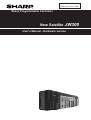
New Satellite JW300
User's Manual - Hardware version
We thank you for your purchase of the SHARP programmable controller JW300.
This booklet (user's manual, hardware version) explains mainly the JW300's hardware; the
system configuration, specifications, installation method etc.
Carefully read this user's manual, hardware version and the instruction manual attached to
each module so that you are able to operate JW300 properly, having thoroughly familiarized
yourself with the functions of the system module and their operation method.
As for the description concerning software factors such as instruction words of the JW300,
please refer to the JW300 programming manual ladder instruction version.
Precautions
- When you plan to use SHARP programmable controllers (hereafter referred to as "PLCs"),
you are requested to design each system so that even if a fault or malfunction occurs within
the PLC, it will not lead to a serious accident in your system. You should incorporate back-up
measures and fail-safe features in your system that will thoroughly protect your system from
malfunctions if a fault or error occurs in the PLC.
- SHARP PLCs are designed and manufactured with the idea that they will be used in general
applications in ordinary industries. Therefore, they must not be used in specific applications
that can affect the health or safety of the public, such as nuclear power plants and other
power generating plants. Such applications require a special warranty of quality that SHARP
explicitly does NOT offer for these PLCs. However, if a user will certify that he/she does not
requires a special quality warranty on the PLC, and will limit the use of the PLC to non critical
areas of these applications, SHARP will agree to such use.
If you are planning to use SHARP PLCs for applications that may affect the lives of human
beings and property, and you need particularly high reliability performance, such as in the
fields of aviation, medicine, transportation, combustion and fuel processing equipment,
passenger cars, amusement park rides, and safety equipment, please contact our sales division
so that we can confirm the required specifications.
Notes
- Though this manual is produced with the almost care, if you have any questions and inquiries,
please feel free to contact our dealers.
- The whole or partial photocopy of this booklet is prohibited.
- Contents of this booklet may be revised for improvement without notice.
Safety precautions
Read this manual and attached documents carefully before installation, operation, maintenance and
checking in order to use the machine correctly. Understand all of the machine knowledge, safety
information, and cautions before starting to use. In this instruction manual, safety precautions are ranked
into "danger" and "caution" as follows.
Danger
: Wrong handling may possibly lead to death or heavy injury.
Caution
: Wrong handling may possibly lead to medium or light injury.
Even in the case of
Caution , a serious result may be experienced depending on
the circumstances. Anyway, important points are mentioned. Be sure to observe them
strictly.
The picture signs of Prohibit and Compel are explained below.
: It means don’ts. For example, prohibition of disassembly is indicated as (
: It means a must. For example, obligation of grounding is indicated as (
).
).
1) Installation
Caution
• Use in the environments specified in the catalog and instruction manual.
Electric shock, fire or malfunction may be caused when used in the environments of high
temperature, high humidity, dusty or corrosive atmosphere, vibration or impact.
• Install according to the manual.
Wrong installation may cause drop, trouble or malfunction.
• Never admit wire chips or foreign matter
Or fire, trouble or malfunction may be caused.
2) Wiring
Compel
• Be sure to ground.
Unless grounded, electric shock or malfunction may be caused.
Caution
• Connect the rated power source.
Connection of a wrong power source may cause a fire.
• Wiring should be done by qualified electrician.
Wrong wiring may lead to fire, trouble or electric shock.
3)
Use
Danger
• Don’t touch the terminal while the power is being supplied or you may have on electric shock.
• Assemble the emergency stop circuit and interlock circuit outside of the programmable
controller. Otherwise breakdown or accident damage of the machine may be caused by the
trouble of the programmable controller.
Caution
• "Run" or "stop" during operation should be done with particular care by confirming safety.
Mis-operation may lead to damage or accident of the machine.
• Turn ON the power source in the specified sequence. Turn ON with wrong sequence may
lead to machine breakdown or accident.
4) Maintenance
Danger
• Never connect battery in wrong polarity, or charge, disassemble, heat, throw into fire, or
short-circuit. Or it may be broken or ignited.
• Do not subject the battery to impact of any kind. Do not pull on the lead wires of the battery,
or liquid leakage accident may occur.
Prohibit
• Don’t disassemble or modify the modules.
Or fire, breakdown or malfunction may be caused.
Caution
• Turn OFF the power source before detaching or attaching the module.
Or electric shock, malfunction or breakdown may be caused.
• Replace with the fuses in specified ratings only.
Or electric shock, malfunction may be caused.
Chapter 1 Outline
Chapter 2 Precautions for use
Chapter 3 System configuration
Chapter 4 Name and function of each part
Chapter 5 Installation
Chapter 6 Wiring
Chapter 7 Directions for use
Chapter 8 Maintenance and check
Chapter 9 Specifications
Appendix
Table of contents
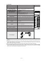
Chapter 1:
Outline · · · · · · · · · · · · · · · · · · · · · · · · · · · · · · · · · · · · · · · · · · · · · · · · · · · · 1-1
Chapter 2
Precautions for use · · · · · · · · · · · · · · · · · · · · · · · · · · · · · · · · · · · · · · · 2-1 to 2
Chapter 3
System configuration · · · · · · · · · · · · · · · · · · · · · · · · · · · · · · · · · · · · · 3-1 to 20
3-1
3-2
[1]
[2]
[3]
[4]
[5]
[6]
[7]
[8]
[9]
3-3
3-4
Chapter 4
4-1
4-2
[1]
[2]
4-3
[1]
[2]
[3]
4-4
[1]
[2]
[3]
[4]
4-5
[1]
[2]
Chapter 5
5-1
5-2
[1]
[2]
5-3
5-4
5-5
[1]
[2]
[3]
5-6
Basic system configuration 3-1
System configuration using communication 3-6
Communication system using communication port 3-6
Communication system using link module (JW-21CM) 3-7
Communication system using the satellite module (JW-22CM) 3-10
Communication system using the ME-NET (JW-21MN) 3-10
Communication system using the Ethernet (JW-255CM/25TCM) 3-11
Communication system using FL-net (JW-20FL5/T, JW-22FL5/T) 3-12
Communication system using the JW-20DN DeviceNet 3-13
Communication system using the satellite I/O link (JW-23LMH) 3-15
Communication system using a JW10 link module (JW-25CM) 3-16
System design procedures 3-18
Precautions on system design 3-19
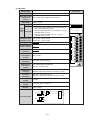
Name and function of each part · · · · · · · · · · · · · · · · · · · · · · · · · · · · · 4-1 to 18
Control module 4-1
Power supply module 4-3
JW-301PU/31PU/22PU 4-3
JW-303PU 4-5
Input/output module 4-6
8/16 points module 4-7
32 points module 4-8
64 points module 4-9
Basic/expansion rack panel 4-10
Basic rack panel 4-10
Expansion rack panel 4-11
Rack No. (expansion rack panel) 4-12
Important points when using basic / expansion rack panels 4-15
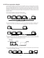
I/O bus expansion adapter 4-16
JW-31EA
4-17
JW-32EA
4-17
Installation · · · · · · · · · · · · · · · · · · · · · · · · · · · · · · · · · · · · · · · · · · · · · · 5-1 to 9
Precautions for installation 5-1
Installation of basic/expansion rack panel 5-2
Installation dimensions of basic/expansion rack panel 5-2
Installation of basic/expansion rack panel in control panel 5-3
Installation of power supply module 5-5
Installation of control module 5-6
Installation of I/O / special I/O / option module 5-7
Installation to a basic/expansion rack panel 5-7
Installation of module cover 5-8
Installation of input/output module side board 5-8
Installation of I/O bus expansion adapter 5-9
Chapter 6
6-1
6-2
[1]
[2]
6-3
6-4
[1]
[2]
6-5
[1]
[2]
Chapter 7
7-1
7-2
7-3
[1]
[2]
[3]
[4]
7-4
[1]
[2]
7-5
[1]
[2]
7-6
[1]
[2]
[3]
[4]
Chapter 8
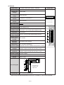
Wiring · · · · · · · · · · · · · · · · · · · · · · · · · · · · · · · · · · · · · · · · · · · · · · · · · 6-1 to 21
Precaution for wiring 6-1
Wiring communication ports 6-9
Pin arrangement of communication port 6-9
Wiring figure 6-11
Wiring for power supply module 6-13
Wiring to I/O module 6-15
Terminal block type of 8/16 points 6-15
Connector type of 32/64 points 6-16
Wiring to basic/expansion rack panel 6-18
Installation of I/O expansion cable 6-18
Wiring for 5 VDC cable, process of panel wiring 6-20
Directions for use · · · · · · · · · · · · · · · · · · · · · · · · · · · · · · · · · · · · · · · · 7-1 to 63
Current consumption of module 7-1
How to calculate the heat value of the JW300 when designing panels 7-4
Allocation of relay numbers 7-5
Setting I/O addresses 7-5
I/O relays allocated to each module 7-9
Number of input/output points and allocation of input/output relays 7-10
Allocation example of relay no. 7-12
Data memory for special I/O, option, device net, I/O link, and option module 7-13
Data memory for special I/O module 7-15
Data memory for option, device net, and I/O link
7-16
Precautions for operating I/ module 7-17
Precautions for operating input module 7-17
Precautions for operating the output module 7-23
Computer link using communication port 7-29
Communication method 7-30
Communication conditions 7-31
Communication format 7-33
Command (response) 7-38
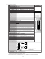
Maintenance and check · · · · · · · · · · · · · · · · · · · · · · · · · · · · · · · · · · · 8-1 to 12
8-1 Self-diagnosis function 8-1
[1] Abnormality not detected by self-diagnostic function 8-1
[2] Self-diagnosis function (Error code table) 8-2
8-2 Troubleshooting 8-4
[1] State of LED 8-4
[2] Precondition of check flow 8-4
[3] Prepare for causing trouble 8-4
[4] Check flow 8-5
8-3 Battery 8-9
[1] Connecting the memory backup battery 8-9
[2] Battery replacement 8-10
[3] Exchange method of batteries 8-11
[4] Internal flash ROM and PC card use 8-12
Chapter 9
9-1
9-2
9-3
9-4
[1]
[2]
[3]
[4]
9-5
[1]
[2]
9-6
9-7
9-8
9-9
[1]
[2]
[3]
[4]
[5]
Appendix
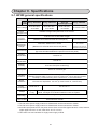
Specifications · · · · · · · · · · · · · · · · · · · · · · · · · · · · · · · · · · · · · · · · · · · 9-1 to 24
JW300 general specifications 9-1
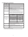
JW300 system specifications 9-2
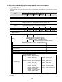
Control module performance and communication specifications 9-3
Specifications of I/O module 9-7
Input module 9-7
Output module 9-12
I/O module JW-232M 9-17
Special I/O module 9-18
Specifications of power supply module 9-20
JW-301PU/22PU/31PU 9-20
JW-303PU 9-21
Specifications of I/O bus expansion adapter 9-22
Specifications of basic rack panel 9-22
Specifications of expansion rack panel 9-22
Outline dimension drawings 9-23
Control module 9-23
Power supply module 9-23
I/O module 9-23
I/O bus expansion adapter 9-24
Basic/expansion rack panel
9-24
· · · · · · · · · · · · · · · · · · · · · · · · · · · · · · · · · · · · · · · · · · · · · · · · · · · · · · A-1 to 8
Appendix-1
Appendix-2
Appendix-3
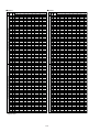
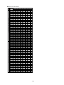
Allocation of the relay No. for the JW-264N and JW-262S A-1
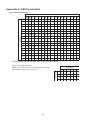
ASCII code table A-6
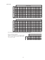
Binary/octal/decimal/hexadecimal/BCD code correspondence table A-8
Chapter 1. Outline
The New Satellite JW300 series are high-speed, high-performance programmable controllers for medium
and large-scale control systems. These are high-level models of the JW30H series.
■
Features
(1) High-speed processing and large memory capacity
- High processing speeds of 33 ns for basic instructions, and 132 ns for application instructions (The
overall processing speed will be approximately 20% faster than our conventional JW30H model.)
- Large, 25 K-word maximum capacity for program memory and 8 M-bytes maximum for file registers
(both approximately 4 times larger than that of the JW30H).
(2) Compatible with memory cards
- Programs and parameters can be backed up on CF cards.
- Extensions to file memory, logging data, etc. can be stored on SRAM cards.
(3) Equipped with a USB port
The JW300 can exchange commands and data with PCs, at high speeds, through its USB port.
(4) Equipped with three ports for communication
There are two ports on the control module (one port on the JW-311CU/312CU) and one port on the I/
O bus expansion adapter (JW-32EA), which can be used for communication. These make it easy to
connect to a control terminal or image sensor camera.
(5) Structured programs / block operation
- You can separate the programs that run on the JW300 into a few blocks so that the PLC can operate
various machines independently, for trial operations and other purposes.
- Each program block can be further separated into sub programs to save programming effort. This will
make it possible to design some programs in parallel. These sub programs can be handled as
standardized modules and can be reused.
(6) Built in faulty equipment diagnosis function
Just program relay numbers and monitor times and the PLC can monitor facilities. This feature makes
for significant savings in writing ladder programs and for detecting errors.
(7) A variety of models
- Ten control module models are available. You can choose the one that best matches your system's
control scale and budget.
- All of the I/O modules and special I/O modules available for the JW20H/30H series can be used with
the JW300. Optional modules for the JW20H/30H also can be used if they are labeled as "compatible
with the JW300."
- A Windows version of our ladder logic programming software, the JW-300SP, is available to support
editing of structured programs.
The JW-15PG hand-held programmer is available to modify and monitor programs on site.
(8) Compatible with various open networks
The JW300 series is Ethernet compatible for communication, FL-net compatible for control, and
DeviceNet compatible for the field. It is also AS-I compatible for sensor applications. These devices
can exchange data with various layers, without any barriers.
1-1
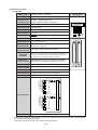
Chapter 2. Precautions for use
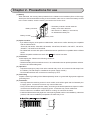
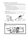
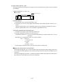
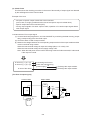
(1) Battery
When delivered, the memory backup batteries in the JW300 control modules (JW-311CU through
362CU) are disconnected. Before using a control module, make sure to connect the battery module
to the control module, clear the memory and set the time for the clock.
- The battery module is stored under the
battery cover when delivered.
- See section 8-3. "Battery" in this manual,
for details about battery life.
Battery connector
Battery module
Battery cover
(2) Option modules
- If you will be using any of the option modules below, make sure to confirm that they are compatible
with the JW300 series.
JW-21CM, JW-22CM, JW-21MN, JW-255CM, JW-25TCM, JW-20FL5, JW-20FLT, JW-22FL5,
JW-22FLT, JW-22SU and JW-25CM.
- The JW300 will not work with option modules that are not specified as compatible with the JW300
series.
- JW300 compatible modules are stuck with 300 mark at their front side.
(3) Installation
Avoid keeping the JW300 in the following conditions:
- Direct sunlight.
- Relative humidity which exceeds 35 to 90 %. No condensation due to rapid temperature variation.
- Corrosive and flammable gases.
(4) Operation
- Prepare an emergency stop circuit at the external relay circuit, and connect the halt output from
the JW300. (The halt output is installed in the power supply module.)
- Don't handle switches and connectors excessively by force.
(5) Grounding
Prepare a class-D grounding of the JW300 separately. Never co-ground with high power equipment
grounding lines.
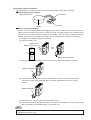
(6) Installation
- Securely fasten the retaining screws in each module, and confirm again that it is fastened prior
to supply power. Looseness of screws may cause malfunction.
- Firmly connect cable (I/O expansion cable), connecting to the basic/expansion rack panel. Confirm
connectors are fastened prior to supplying power. Looseness may cause malfunction.
- Each module has a ventilation hole to allow for cooling. Do not block the holes.
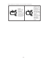
- Install the JW300 horizontally against a control panel (parallel, wall-mount installation), otherwise
(vertical, wall-mount installation) temperature increase may occur.
←
O
F
F
PROTECT
INIT
RESET
RUN
FLT
CM1
CM2
C
A
R
D
USB
SV
▲
PULL
PG/COMM1
電池交換
時期
This
battery
expires
電池の交換
は5分以内
に行ってく
ださい
Exchange
the battery
within
5minutes.
PG/COMM2
2-1
(7) Wiring
- Be aware not to confuse the connection polarity of 5 VDC on the expansion rack panel. Otherwise,
rack panel and I/O module etc. may be damaged.
- Keep the input/output lines away from high voltage or strong current lines such as power lines.
(8) Cautions for static electricity
Significant volume of static electricity may build up on the human body in extremely dry conditions.
Prior to touching the JW300, discharge the static electricity by touching grounded metals.
(9) Cleaning
Use the soft cloths for cleaning. Volatile solvents (alcohol, paint thinner, freon etc.) and wet rags
may cause deformation or change of color.
(10) Storage
Keep the JW300 in cool and dry conditions as it equipped with a battery for memory backup. High
ambient temperature may shorten its battery life.
Do not put other objects on the JW300.
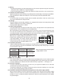
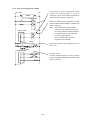
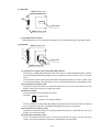
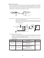
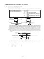
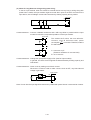
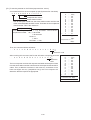
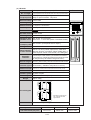
(11) Short circuit protection
If the load connected to the output terminal shorts circuits, the output device or the printed circuit
board may burn. Insert a protective fuse in the output lines.
We recommend that you install protective fuses in each line, even if the external devices have
fuses for each common unit. These common line fuses are to protect the device against burnout
caused by overload, and do not protect against overcurrent of output element and load.
Output module
[Precautions when using a rated voltage power source]
Load Fuse
0
When you use a power supply for loads that have a current
1
limiting circuit, provide fuses that match the load rating of
each output module. If the load is shorted, and the current
limiting circuit functions, the short-circuit current will flow at
COM
current level lower than needed to blow the fuse.
Power supply load
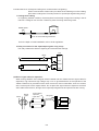
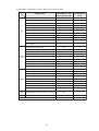
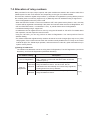
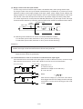
(12) Insulation transformer
Choose isolation transformer with a capacity 20% or higher than the rated load. When a transformer
of the same capacity as that of the rated load is used, the primary input voltage might exceed the
rated transformer capacity.
Power supply
module
Power
consumption*
Transformer
capacity
60 VA or less
72 VA or more
70 VA or less
85 VA or more
JW-301PU
JW-22PU
* Maximum load capacity when one power
supply module is used.
JW-31PU
JW-303PU
(13) Max. No. of I/O points
Each control module has a maximum number of input and output points, but the number of relay
points affecting the maximum number of input and output points varies with the type of the module.
It must be noted that it is different from the number of relay assignments. => See page 7-10
(14) Special I/O modules
If a preset scanning time is too short ( less than 2 ms), the special I/O module such as JW-21SU
and JW-22DA may not function normally.
To avoid this malfunction, set a longer scanning time using a constant scanning (set 3 ms or more
on the system memory #0226) or other functions.
(15) Insulation resistance and dielectrical strength tests of the power supply module
When testing insulation resistance or dielectrical strength of the JW-301PU/31PU power supply
modules, be sure to remove the short bar connected between the SHORT terminal and the GND
terminal. If a test is carried out without removing the short bar, internal elements of the module
may be damaged.
2-2
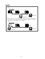
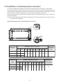
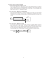
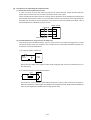
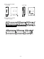
Chapter 3. System configuration
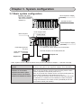
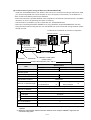
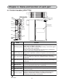
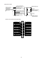
3-1 Basic system configuration
Expansion rack panel
(The number of modules
that can be connected:
Maximum 7)
I/O bus expansion adapter*
(JW-32EA)
Terminal connector
(Attached to JW-31EA)
I/O / special I/O module
I/O expansion cable
(Total length: max.50m)
Power supply module
Basic rack panel
Control module
←
O
F
F
PROTECT
INIT
RESET
RUN
FLT
CM1
CM2
C
A
R
D
USB
SV
▲
PULL
PG/COMM1
電池交換
時期
This
battery
expires
I/O bus expansion adapter *
(JW-31EA)
電池の交換
は5分以内
に行ってく
ださい
Exchange
the battery
within
5minutes.
PG/COMM2
Hand-held programmer
JW-15PG
Ladder logic programming
JW-300SP
software
I/O / special I/O / option / device net / I/O link module
Personal computer, LCD control terminal, etc.
Computer link
Support tool
* Note: System can be configured without using an I/O bus expansion adapter. => See the next page.
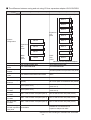
Number of connectable rack
panels
Number of I/O module,
special I/O module, option
module, Device net module,
and I/O link module to mount
Max. 8 sets in total of 1 basic rack panel and 7 expansion rack panel.
(In case of using the I/O bus expansion adapter JW-31EA/32EA.)
Total of 64 sets can be mounted.
- Max. of 64 I/O modules can be mounted including both the basic
and the expansion rack panels (racks 0 to 7).
- Max. of 64 special I/O modules can be mounted including both the
basic and the expansion rack panels (racks 0 to 7).
- Max. of 8 option modules can be mounted on the basic rack panel.
- A maximum of 4 modules can be installed on a basic rack panel
along with the device net master module (JW-20DN) and an I/O
link master module (JW-23LMH).
3-1
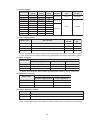
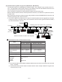
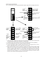
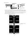
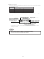
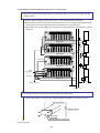
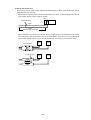
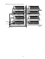
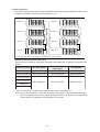
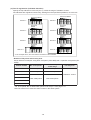
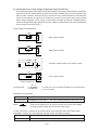
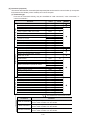
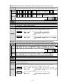
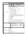
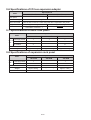
■ The difference between using and not using I/O bus expansion adapter JW-31EA/32EA
When not using I/O bus expansion adapter
When using I/O bus expansion adapter
JW-32EA I/O bus expansion adapter
→
32
E
A
Rack 6
32
E
A
Rack 5
32
E
A
Rack 4
32
E
A
Rack 3
Rack 3
32
E
A
Rack 2
Rack 2
32
E
A
Rack 1
Rack 1
32
E
A
Rack 0
31
E
A
Expansion
rack
panel
System
configuration
Expansion
rack
panel
Basic
rack
panel
Basic
rack
panel
Rack 0
→
Rack 7
JW-31EA I/O bus expansion adapter
Basic rack panel
Expansion rack
panel
JW-314KB/316KB/318KB
JW-314KB/316KB/318KB
JW-34ZB/36ZB/38ZB
JW-34ZB/36ZB/38ZB
I/O bus expansion
adapter
JW-31EA (Install in basic rack panel)
JW-32EA (Install in all expansion rack panel)
-
I/O expansion
cable
JW-203EC/207EC/22EC/25EC/210EC
JW-05EC/1EC/3EC/10EC/20EC/30EC/
50EC
No. of racks
4 racks max.
8 racks max.
Cable total length
distance
14 m max. (Max. 10 m between rack
panels)
50 m max. (Max. 50 m between rack panels)
No. of I/O modules Max. 32 sets on basic/expansion rack
panel (racks 0 to 3)
Max. 64 sets on basic/expansion rack panel
(racks 0 to 7)
No. of special I/O
modules
Max. 32 sets on basic/expansion rack
panel (racks 0 to 3)
Max. 32 sets on basic/expansion rack panel
(racks 0 to 3)
No. of option
modules
Max. 8 sets for basic rack panel (rack 0)
Max. 8 sets for basic rack panel (rack 0)
No. of device net
modules
Max. 4 sets for basic rack panel (rack 0)
No. of I/O link
modules
Max. 4 sets for basic rack panel (rack 0)
Max. 4 sets for basic rack panel (rack 0)
*
*
Connection support
tool with expansion Unavailable
rack panel
Max. 4 sets for basic rack panel (rack 0)
Available for connected I/O bus
expansion adapter JW-32EA
* Maximum 4 sets including the JW-20DN and JW-23LMH.
3-2
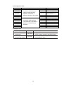
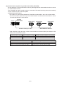
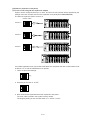
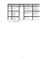
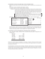
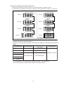
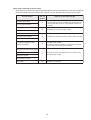
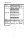
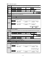
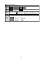
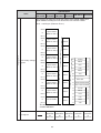
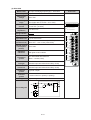
(1) Control module
Model mame
Program
capacity
File register
capacity
Memory
card I/F
JW-311CU
8K words
-
None
JW-312CU
8K words
-
Yes
JW-321CU
16K words
32K bytes
None
JW-322CU
16K words
32K bytes
Yes
JW-331CU
32K words
128K bytes
None
JW-332CU
32K words
128K bytes
Yes
JW-341CU
64K words
512K bytes
None
JW-342CU
64K words
512K bytes
Yes
JW-352CU
128K words
2048K bytes
Yes
JW-362CU
256K words
8192K bytes
Yes
No.of in/out Communication Compatible with
(maximum)
port
multi CPU * 1
512 points
2 ports
Unavailable
3 ports
Available
1024 points
4096 points
* 1: Will be available soon.
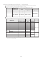
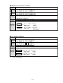
(2) Power supply module
Approved Approved
UL/CSA
CE
Model name
Specification
JW-303PU *2
85 to 264 VAC. Power capacity: 5 VDC 4.5 A
-
-
JW-301PU *3
85 to 264 VAC. Power capacity: 5 VDC 3.5 A
-
-
JW-31PU
85 to 132 VAC. Power capacity: 5 VDC 3.5 A
O
O
JW-22PU
20.4 to 32 VDC. Power capacity: 5 VDC 3.5 A
-
-
*2: The JW-33PU power supply module for the JW20H/30H can also be used with the JW300.
*3: The JW-21PU power supply module for the JW20H/30H can also be used with the JW300.
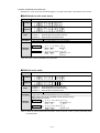
(3) Basic rack panel
No. of slots
Model name
For power supply module For control madule For I/O module *4
JW314KB
1
1
4
JW316KB
1
1
6
JW318KB
1
1
8
*4: Mount I/O, special I/O, option, device net, and I/O link module on the I/O module slot.
(4) Expansion rack panel
No. of slots
Model name
For power supply module
For I/O module *5
JW-34ZB
1
4
JW-36ZB
1
6
JW-38ZB
1
8
*5: Mount I/O and special I/O module on the I/O module slot.
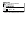
(5) I/O bus expansion adapter
Model name
Specifications
JW-31EA
Mounting to basic rack panel
JW-32EA
Mounting to expansion rack panel, with PG port
Use an I/O bus expansion adapter when more than 5 racks (max. 8 racks) on the rack panel are
used, or when total length of I/O expansion cables is longer than 15 meters (max. 50 meters).
3-3
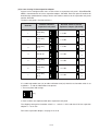
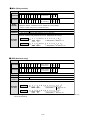
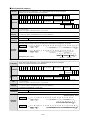
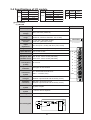
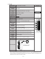
(6) I/O / special I/O / option / device net / I/O link module
Model
name
JW-203N
Specifications
8 points input, 200/240 VAC
JW-211NA 16 points input, 100/120 VAC
JW-212NA 16 points input, 12/24 VDC
JW-214NA 16 points input, 12/24 VDC (high speed type)
I/O
JW-234N
32 points input, 12/24 VDC (high speed type, connector connection)
JW-204SA
8 points output, 250 VAC/30 VDC, 2 A relay output (separated
common)
JW-212SA 16 points output, 5/12/24 VDC, 0.5 A, transistor output (sink output)
JW-213SA 16 points output, 100/200 VAC, 1 A triac output
JW-214SA 16 points output, 250 VAC/30 VDC, 2 A, relay output
Special I/O
Option
Device
net
I/O
link
JW-232S
32 points output, 5/12/24 VDC, 0.1 A, transistor output (sink output,
connector connection)
JW-232M
16 points input, 12/24 VDC
16 points output, 5/12/24 VDC, 0.1 A, transistor output (sink output,
connector connection)
JW-264N
64 points input, 24 VDC (high speed type, connector connection)
JW-262S
64 points output, 5/12/24 VDC, 0.1 A, transistor output (sink output,
connector connection)
JW-21HC
High speed counter: 100 kHz 1 ch
JW-22HC
High speed counter: 100 kHz/200 kHz 2 ch
JW-24AD
Analog input: 4 points 13 bits
JW-22DA
Analog output: 2 points 16 bits
JW-22DU
ID control: Microwave
JW-21SU
Serial interface 1 port (RS-232C/422A)
JW-21PS
Pulse output, number of control axis: 1. Max speed: 250 kpps.
JW-21CM
Select from computer link / data link / remote I/O functions by
switching.
JW-22CM
Network module
JW-21MN
ME-NET module
JW-255CM Ethernet module 10BASE-T
JW-25TCM Ethernet module 10BASE-T
JW-20FL5 FL-net module (Compatible with ver.1) 10BASE5
JW-20FLT FL-net module (Compatible with ver.1) 10BASE-T
JW-22FL5 FL-net module (Compatible with ver.2) 10BASE5
JW-22FLT FL-net module (Compatible with ver.2) 10BASE-T
JW-22SU
JW-25CM
Serial interface 2 ports (RS-232C/RS-422, RS-232C)
JW10 link module
JW-20DN
Device Net master module
JW-23LMH
JW-21RS
*
I/O link master station, up to 32 slave stations, max. 504 points, 345.6
kbits/s / 172.8 kbits/s
Remote I/O slave module
* Make sure to use the JW300 series compatible products for the JW-21CM, JW-22CM, JW-21MN,
JW-255CM, JW-25TCM, JW-20FL5, JW-20FLT, JW-22FL5, JW-22FLT, JW-22SU, and JW-25CM.
If your modules are not compatible with the JW300 series, the JW300 series modules will not
operate normally.
3-4
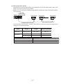
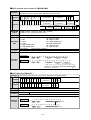
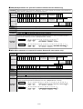
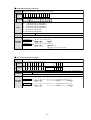
(7) I/O expansion cable
Model name
JW-203EC
JW-207EC
JW-22EC
JW-25EC
JW-210EC
JW-05EC
JW-1EC
JW-3EC
JW-10EC
JW-20EC
JW-30EC
JW-50EC
Specifications
Connection cables between
a basic rack panel and an
expansion rack panel, or
between expansion rack panels.
Connection cables between
a JW-31EA and a JW-32EA, or
between a JW-32EA and a
JW-32EA.
30 cm
70 cm
2m
5m
10 m
50 cm
1m
3m
10 m
20 m
30 m
50 m
Accessories
5 V DC cable (30cm) x 1
5 V DC cable (70cm) x 1
5 V DC cable (2m) x 1
Short connector x 1
Short connector x 1
Short connector x 1
5 V DC cable (50 cm) x 1
5 V DC cable (1 m) x 1
None
None
None
None
None
(8) Support tools
Model name
Name
Specifications
Hand-held
programmer
JW-15PG
4 digit 16 characters LCD, 45 keys, program,
monitor, change, terminal, and initial function.
Ladder logic
programming software
JW-300SP
Ladder logic programming software
for Windows XP, 2000
3-5
3-2 System configuration using communication
For details of the communication modules (option / device net / I/O link modules), refer to the each
module user’s manual.
When using the optional modules listed below, make sure that the ones you select are compatible with
the JW300 series.
JW-21CM, JW-22CM, JW-21MN, JW-255CM, JW-25TCM, JW-20FL5, JW-20FLT, JW-22FL5, JW22FLT, JW-22SU, JW-25CM.
- The JW300 will not work with option modules that are not specified as compatible with the JW300
series.
- JW300 compatible modules are stuck with 300 mark at their front side.
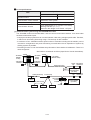
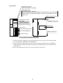
[1] Communication system using communication port
By using a communication port of the JW300, the JW300 can communicate with a host computer such
as a personal computer and a LCD control terminal. [Computer Link]
The control module (JW-3**CU) has PG/COMM1 port, PG/COMM2 port as communication port. I/O
bus expansion adapter has an EA-PG port.
JW-3**CU
JW300
←
O
F
F
PROTECT
INIT
RESET
RUN
FLT
CM1
CM2
C
A
R
D
USB
SV
▲
PULL
PG/COMM1
電池交換
時期
This
battery
expires
電池の交換
は5分以内
に行ってく
ださい
Exchange
the battery
within
5minutes.
Host computer
PG/COMM2
PG/COMM2 port:RS-232C or RS-422A
Host computer
PG/COMM1 port:RS-232C or RS-422A
Item
Specifications
RS-232C connection
RS-422A connection
No. of connected
sets of JW300
1 sets (1:1 connection)
Nax. 31sets (1:N connection)
Communication line
Shielded cable
Max.15m
Shieled rwisted pair cable
Cabletotal length; max. 1km
4-wire system
(Party line connection)
Transfer rate
Data style
Character used
230400/115200/76800/38400/19200/9600 bits/s
Start bit
Data length
Party bit
stop bit
: 1 bits
: 7/8 bits
: 1 bits (odd/even/none)
: 1/2 bits
ASCII alphanumeric characters
- JW-311CU/312CU do not have PG/COMM 2 port.
- Please note that the EA-PG port (JW-32EA) cannot be used for "RS-232C" communication and does
not offer a data transfer speed of 230,400 bps. => See page 7-30.
- For operational method of communication port, see page 7-29, "Computer link using communication
port."
3-6
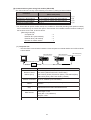
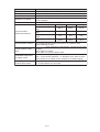
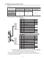
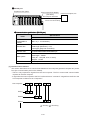
[2] Communication system using link module (JW-21CM)
- The JW-21CM can use any of the following 4 functions by setting its internal switch.
Functions
Computer link
Data link DL1 (N:M method)
Data link DL9 (1:N method)
Remote I/O master station
Total number of mountable modules
(Basic rack panel)
Up to 7
Up to 6 (total of master and slave stations)
Up to 6 (total of master and slave stations)
Up to 1
=> (1)
=> (2)
=> (3)
=> (4)
- The JW-21CM is an option module, and up to 7 modules of JW-21CM (including other option modules)
can be mounted only on a basic rack panel. Total number of mountable modules varies according to
the functions to be used, as shown above.
[Mounting example]
Computer link
:2
Data link DL1 (N:M method)
:2
Data link DL9 (1:N method)
:2
Remote I/O master station
:1
Total
7
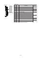
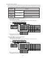
(1) Computer link
- This link offers communication between a host computer as a master station and a JW-21CM as
a slave station.
JW-21CM (slave)
JW-21CM (slave)
Host computer
JW300
JW300
JW-340CU
JW-340CU
CM1
ON
RUN ↑
CM2
FLT PROTECT
JW-10CM (slave)
JW70H
CM1
ON
RUN ↑
CM2
FLT PROTECT
USB
USB
▲
PULL
▲
PULL
PG/COMM1
PG/COMM1
電池交換
時期
This
battery
expires
電池交換
時期
This
battery
expires
電池の交換
は5分以内
に行ってく
ださい
Exchange
the battery
within
5minutes.
電池の交換
は5分以内
に行ってく
ださい
Exchange
the battery
within
5minutes.
PG/COMM2
PG/COMM2
RS-232C/422 converter
RS-485
RS-232C
Max, of 31 slave stations
Z-101HE
Items
Names of slave
stations (PLC)
Specifications
JW-21CM (JW300, JW30H, JW20H)
JW-10CM (JW50H/70H/100H, W70H/100H)
ZW-1K0CL2 (W100), ZW-501CL2(W51), ZW-160CL2(W16)
ZW-10CL2 (W10), and Z-331J/332J (J-board)
Numbers of slave
stations connected
Up to 31 modules (1:N connection)
Communication line
cables
A shielded-twist pair cable. Max. length: 1 km. 2-wire / 4-wire
systems.
Transfer speed (baud
19200/9600/4800/2400/1200/600/300 bits/s
rate)
Data formats
Used character
Start bit: 1 bit
Data length: 7 bits
Parity bits: 1 bit (odd/even)
Stop bit: 2 bits
ASCII alphanumerical characters
3-7
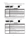
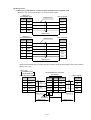
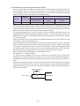
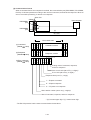
(2) Data-link DL1
- This communication system can change data between a master and a slave station, or between
2 slave stations, with a PLC configuration that uses the JW-21CM as a master station or a slave
station. (N:M method)
JW-340CU
JW-340CU
CM1
ON
RUN ↑
FLT PROTECT
JW70H
JW300
JW300
CM2
JW-10CM (slave)
JW-21CM (slave)
JW-21CM (slave)
CM1
ON
RUN ↑
CM2
FLT PROTECT
USB
USB
Slave station: 15 sets max.
▲
PULL
▲
PULL
PG/COMM1
PG/COMM1
電池交換
時期
This
battery
expires
電池交換
時期
This
battery
expires
電池の交換
は5分以内
に行ってく
ださい
Exchange
the battery
within
5minutes.
電池の交換
は5分以内
に行ってく
ださい
Exchange
the battery
within
5minutes.
PG/COMM2
PG/COMM2
Shielded-twist pair cable Total length max. 1 km 153.6 kbits/s
Items
Specifications
Model name of
JW-21CM (JW300, JW30H, JW20H)
master/slave station JW-10CM (JW50H/70H/100H, W70H/100H)
(PLC)
ZW-501DL1(W51), ZW-160DL1 (W16), Z-331J/332J (J-board)
No. of connected
stations
Max. 16 stations (Including master station)
No. of link bytes
Total 64 bytes (512 points)
- Divided equally according to the number of slave stations when
a JW-21CM or a Z-331J/332J is used as master station. (1 station:
No. of link bytes per
32 bytes, 2 or 3 stations: 16 bytes each, 4 to 7 stations: 8bytes each,
station
and 8 to 15 stations: 4 bytes each.)
- When master station is other than JW-21CM, or Z-331J/332J, up to
64 bytes will be allocated.
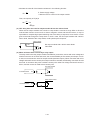
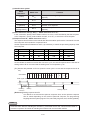
(3) Data-link DL9
- This communication system can exchange data between a master and slave stations, with a
PLC configuration that uses the JW-21CM as a master station or a slave station. It cannot
communicate between slave stations.(1: N method)
JW-21CM (slave)
JW-21CM (slave)
JW300
JW300
JW-340CU
JW-340CU
CM1
ON
RUN ↑
CM2
FLT PROTECT
JW-10CM (slave)
JW70H
CM1
ON
RUN ↑
CM2
FLT PROTECT
USB
USB
Slave station: 15 sets max.
▲
PULL
▲
PULL
PG/COMM1
PG/COMM1
電池交換
時期
This
battery
expires
電池交換
時期
This
battery
expires
電池の交換
は5分以内
に行ってく
ださい
Exchange
the battery
within
5minutes.
電池の交換
は5分以内
に行ってく
ださい
Exchange
the battery
within
5minutes.
PG/COMM2
PG/COMM2
Shielded-twist pair cable Total length max. 1 km 153.6 kbits/s
Item
Specifications
JW-21CM (JW300, JW30H, JW20H)
Model name of
JW-10CM (JW50H/70H/100H, W70H/100H)
master/slave station
ZW-1K0DL9 (W100), ZW-501DL9(W51), ZW-160DL9 (W16)
(PLC)
Z-331J/332J (J-board)
No. of slave
stations connected
Max. 15 sets
No. of link bytes
- Select from 512/256/128/64 bytes when a master station is a JW21CM, or Z-331J/332J.
- When a master station is other than a JW-21CM, or Z-331J/332J, up
to 512 bytes will be allocated.
- Divided equally according to the number of slave stations when a
JW-21CM or a Z-331J/332J is used as master station. (1or 2 stations:
No. of link bytes per 128 bytes each, 3 or 4 stations: 64 bytes each, 5 to 8 stations: 32
station
bytes each, and 9 to 16 stations: 16 bytes each.
- When master station is other than JW-21CM, or Z-331J/332J, total of
max. 127 bytes will be allocated.
3-8
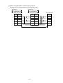
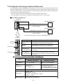
(4) Remote I/O master station
- The system can communicate between a JW-21CM as remote I/O master station and remote I/O slave
station.
JW-21CM
(Master station)
JW-21RS (slave) JW-21RS (slave) JW-21RS (slave) JW-21RS (slave)
JW300
JW-340CU
CM1
ON
RUN ↑
CM2
FLT PROTECT
USB
▲
PULL
PG/COMM1
電池交換
時期
This
battery
expires
電池の交換
は5分以内
に行ってく
ださい
Exchange
the battery
within
5minutes.
PG/COMM2
Shielded-twist pair cable Total length max. 500 m
Item
307.2 kbits/s
Slave station
4 sets max.
Specifications
Model name of slave
station(PLC)
JW-21RS (JW300, JW30H, JW20H)
ZW-501RS1 (W51), ZW-160RS1 (W16), ZW-10RS1 (W10)
Number of slave
stations connected
Max. 4 sets
Number of remote I/O
points
Total point max. 512 (64 bytes)
Number of I/O points
per station
128 points (16 bytes)
Number of special I/O
modules mounted on
a JW-21RS
Max. 8 (Total of 4 slave stations)
3-9
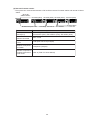
[3] Communication system using the satellite module (JW-22CM)
The system can communicate between PLCs or between personal computers by mounting a JW-22CM
on a JW300.
- It can realize data linking (N:M method) and computer linking on the same communication line.
- The JW-22CM is an option module, and up to 7 modules (including other option modules) can be
mounted only to a basic rack panel.
JW-22CM
(master station)
JW-22CM (slave)
JW300
JW300
FLT PROTECT
CM1
ON
RUN ↑
CM2
FLT PROTECT
USB
USB
456
23
456
901
23
456
23
456
901
901
78
901
78
78
901
78
23
456
901
78
78
456
ON
RUN ↑
23
CM1
PC-98
JW-340CU
JW-340CU
CM2
JW-20CM (slave)
JW70H
23
▲
PULL
▲
PULL
PG/COMM1
PG/COMM1
電池交換
時期
This
battery
expires
電池交換
時期
This
battery
expires
電池の交換
は5分以内
に行ってく
ださい
Exchange
the battery
within
5minutes.
電池の交換
は5分以内
に行ってく
ださい
Exchange
the battery
within
5minutes.
PG/COMM2
PG/COMM2
ZW-98CM (slave)
5C-2V coaxial cable Total length max. 1 km 1.25M-bits/s Max. 64 stations
Items
Specifications
JW-22CM (JW300, JW30H, JW20H)
Name of connected models
JW-20CM (JW50H/70H/100H, W70H/100H), Z-335J (J-board)
(PLC, personal computer)
ZW-98CM (PC98), ZW-20AX (IBM/PC, DOS/V)
Max. 64 stations
No. of connected stations
Relay link: Max. 2048 points (64 bytes)
Number of link bytes
Register link: Max. 2048 bytes
Number of linked bytes per Relay link: Max. 2048 points (64 bytes)
Register link: Max. 2048 bytes
station
[4] Communication system using the ME-NET (JW-21MN)
Mount the JW-21MN on the JW300, you can exchange data with equipment that conform to the MENET specifications (PLCs, personal computers, robot controllers, etc.).
- It can realize data link (N:M method) and computer link on the same communication line.
- The JW-21MN is an option module, and up to 7 modules (including other option modules) can be
mounted only to a basic rack panel.
JW-21MN
(master station)
JW-21MN (slave)
JW300
JW300
CM1
ON
RUN ↑
CM2
FLT PROTECT
USB
USB
456
23
456
901
23
456
456
23
23
456
78
901
901
78
78
901
901
78
901
78
78
456
FLT PROTECT
23
ON
RUN ↑
CM2
JW-20MN (slave)
PC-98
JW-340CU
JW-340CU
CM1
JW70H
23
▲
PULL
▲
PULL
PG/COMM1
PG/COMM1
電池交換
時期
This
battery
expires
電池交換
時期
This
battery
expires
電池の交換
は5分以内
に行ってく
ださい
Exchange
the battery
within
5minutes.
電池の交換
は5分以内
に行ってく
ださい
Exchange
the battery
within
5minutes.
PG/COMM2
PG/COMM2
JW-98MN (slave)
5C-2V coaxial cable Total length max. 1 km 1.25M-bits/s Max. 64 stations
Items
Specifications
JW-21MN
(JW300,
JW30H,
JW20H)
Name of connected models
JW-20MN
(JW50H/70H/100H,
W70H/100H), Z-334J (J-board)
(PLC, personal computer)
JW-98MN (PC98), JW-90MN (IBM/PC, DOS/V), etc.
No. of connected stations Max. 64 stations
Number of linked bytes per Relay link: Max. 2048 points (64 bytes)
Register link: Max. 2048 bytes
station
Number of transmission
bytes per station
Max. 1024 bytes total of relay link and register link
3-10
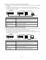
[5] Communication system using the Ethernet (JW-255CM/25TCM)
Install the JW-255CM/25TM on the JW30H, and connect it to a transceiver using a transceiver cable,
you can exchange data with a host computer or any LAN system in the network, on the Ethernet *1.
- Both TCP/IP and UDP/IP protocols are available.
- Data communication is possible between host computers in an Ethernet network and PCs in a satellite
network or on an FL-net spanning two layers of hierarchy.
- Communication is possible by up to 8 nodes with one JW-255CM/25TCM.
- Data can be exchanged between SHARP PLCs using SHARP's unique SEND/RECEIVE function.
- Using the subnet mask routing function, the JW-255CM can communicate with a large network system
through a router.
*1 Ethernet is a trademark of the Xerox Corporation.
JW50H/70H/100H
JW300
Host computer
JW300
JW-340CU
JW-340CU
▲
PULL
▲
PULL
PG/COMM1
PG/COMM1
電池交換
時期
This
battery
expires
電池交換
時期
This
battery
expires
電池の交換
は5分以内
に行ってく
ださい
Exchange
the battery
within
5minutes.
電池の交換
は5分以内
に行ってく
ださい
Exchange
the battery
within
5minutes.
PG/COMM2
PG/COMM2
JW-255CM
JW-255CM
JW-50CM
Transceiver cable
(max. 50 m)
Max. number of stations is 100.
Transceiver
Terminator
10BASE5 coaxial cable
(Yellow cable)
Coaxial cable segment (max. 500 m)
Item
Connection with network
Specifications
JW-255CM
10BASE5
Transmission device
Star
Bus
50 ohms coaxial cable
Station interval
500 m/segments
2.5 km/network
Protocol
structure
100 m/segments
*2
500 m/network
100 sets/segments (10BASE5)
Sharp computer link/original command
Transport
TCP/UDP
Network
IP (ARP)
Data link
Ethernet V2
No. of connections
8
Application
*3
Length multiplied by 2.5 m (10BASE5)
Max. No. of stations
Application
10 BASE-T twisted pair cable
Base band
Transmission method
Max. No. of transfer length
10BASE-T
10M bits/s
Transfer speed
Physical topology
JW-25TCM
Computer link function, send/receive functions, routing function
*2: The max. number of transfer length between stations connecting multiple segments using the
repeater.
*3: Maximum data transfer distance between stations when multiple 10BASE-T segments are
connected using hubs.
3-11
[6] Communication system using FL-net (JW-20FL5/T, JW-22FL5/T)
The JW-20FL5/22FL5 (for 10BASE5) and JW-20FLT/22FLT (for 10BASE-T) are modules for the "FLnet" *1 next generation control system network. They facilitate connection with different devices such as
NC and industrial robot as well as other manufacturers’ PLCs.
- Join to a network is simple by a node automatic entrance and removal function.
- Perform interlock between devices, transfer production instruction, and collection of production result on
a single circuit.
- Easy maintenance thanks to data exchange using SHARP’s unique SEND/RECEIVE instruction and
remote programming and monitor functions.
*1: "FL-net (FA LINK Protocol Network)" is an open FA network system that was suggested by the Japan
FA Open Promotion committee (JOP) in the Production Science Center (governmental foundation)
as a shared standard in the field.
Personal
computer
10BASE5 coaxial cable (500 m max.) Transceiver
FL-net
Terminator
O
F
F
JW-340CU
1
2
Transceiver
cable
(50 m max.)
CM1
ON
RUN ↑
CM2
FLT PROTECT
Other
mfg’s PLC
JW50H/70H
/100H
RC J-board JW20H/30H
Hub
USB
10BASE-T
twisted pair
cable (100 m
max.)
▲
PULL
PG/COMM1
電池交換
時期
This
battery
expires
電池の交換
は5分以内
に行ってく
ださい
Exchange
the battery
within
5minutes.
PG/COMM2
Z-336J
JW-20FL5
JW-50FL
J-board
JW300
JW-340CU
O
F
F
1
2
CM1
ON
RUN ↑
CM2
FLT PROTECT
USB
Maximum number of nodes: 100 / segment
JW50H/70H
/100H
▲
PULL
PG/COMM1
電池交換
時期
This
battery
expires
電池の交換
は5分以内
に行ってく
ださい
Exchange
the battery
within
5minutes.
PG/COMM2
Z-336J
JW-20FLT
JW-50FL
■ Specifications of the communication section
Specifications
Item
JW-20FL5, JW-22FL5
Connection to network
JW-20FLT, JW-22FLT
10BASE5
10BASE-T
Bus
Star
Data transfer media
50 ohm yellow cable
10BASE-T twisted pair cable
Maximum data transfer
distance between
stations
500 m / segment
2.5 km / network *2
10 m / segment
500 m / network *3
Physical topology
Data transfer speed
10 Mbps
Data transfer system
Base band
Protocol configuration
Application
Transport
Network
Data link
FA link protocol
UDP
IP
Ethernet V2
*2: The maximum data transfer distance between stations when more than one segment are connected
using a repeater.
*3: The maximum data transfer distance between stations when multiple 10BASE-T segment are
connected using a hug.
3-12
■ FL-net specifications
Specifications
Item
JW-20FL5, JW-20FLT
JW-22FL5, JW-22FLT
Ver. 1
Applicable version
Ver. 2
Communication control method
Masterless, token system
Number of connecting stations
Maximum 254
Communication function
Cyclic data transfer (n: n, 8 k-bits + 8 K-words)
Message transfer (1:1, 1: n)
Maximum data length of one frame: 1 K-bytes
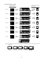
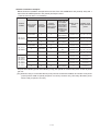
[7] Communication system using the JW-20DN DeviceNet
The JW-20DN conforms to the DeviceNet * and can connect various slave stations. It can share other
facilities inside/outside Japan.
- It employs multi-drop system that can connect between nodes using a single special cable. Therefore,
it offers much wire saving. Branching using a T-branch tap is also available.
- A maximum of four JW-20DN modules (total number of modules including the JW-23LMH) can be
mounted on a single basic rack panel. Shortening communication time or separation of systems by
dividing systems is possible.
- The editing function of scan list facilitates easy allocation of slave station I/O addresses. There is no
need configurator.
*DeviceNet is a trademark of ODVA (Open Device Vendor Association).
JW300
JW300
JW-20DN
JW-20DN
(Master
mode)
MS
NS
SD RD ER PT
S7 S6 S5 S4 S3 S2 S1 S0
FG
JW-20DN
MS
NS
JW-20DN
JW-20DN
(Slave
mode)
SD RD ER PT
S7 S6 S5 S4 S3 S2 S1 S0
MS
NS
SD RD ER PT
S7 S6 S5 S4 S3 S2 S1 S0
FG
JW-20DN
(Master mode)
FG
Termination
resistance
Termination
resistance
Cable (trunk line)
Slave
Cable (trunk line)
JW-D164N
/D162S
/D162M
Cable (branch line)
Slave
Slave
Slave
3-13
Power supply for
communication
(24 VDC)
Power Termination
tap resistance
T branch tap
Slave
Power Termination
resistance
tap
ADDRESS
Sensor Actuator
Power supply for
communication
(24 VDC)
Items
Specifications
Communication protocol Device net or equivalent
Basic operation mode
Master mode, slave mode
No. of connectable nodes A maximum of 63 slave nodes can be connected to one master node.
Max. 4096 points (Max. 512 bytes : Total of input and output points
Number of I/O points
for I/O message)
125 k bits/s, 250 k bits/s, 500 k bits/s
Communication speed
Communication speed
500 kbps
125 kbps
250 kbps
Trunk length using a thick
500 m
250 m
100 m
cable
Trunk length using a thin
Communication
100 m
100 m
100 m
cable
distance (maximum)
Maximum branch line
6m
6m
6m
length
Total length of branch
156 m
78 m
39 m
lines
Communication function
Communication cable
type
Data table assignment
at master mode
Setting the No. of I/O
bytes at slave mode
I/O message function (polling I/O function, bit strobe function),
explicit message function
Special cable (Five conductors: 2 signal wires, 2 power source wires,
1 shield)
- Thick cable: For trunks
- Thin cable: For trunks or branch lines
In the scan list editing mode you can select "allocation in address
order," "even number allocation," or "allocation in the order in which
vacant nodes are occupied" as the method for I/O data mapping
No. of input bytes: 0 to 127 bytes
No. of output bytes: 0 to 127 bytes
3-14
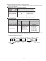
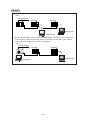
[8] Communication system using the satellite I/O link (JW-23LMH)
The system can communicate between a JW-23LMH as an I/O link master station and an I/O link slave
module.
Up to 4 JW-23LMH modules can be mounted only on a basic rack panel.
JW-23LMH
(master station)
JW300
JW-340CU
CM1
ON
RUN ↑
CM2
FLT PROTECT
(slave)
8-point module
(slave)
(slave)
16-point module 32-point module
(Slave station)
LCD control terminal,
manifold solenoid valve, etc.
USB
▲
PULL
PG/COMM1
電池交換
時期
This
battery
expires
電池の交換
は5分以内
に行ってく
ださい
Exchange
the battery
within
5minutes.
PG/COMM2
Shielded-twist pair cable Total length max. 1 km 172.8 kbits/s
Max. 32 slave stations
345.6 kbits/s *Note
* The communication speed of 345.6 kbits/s can be achieved only when in communication with following
high-speed type slave module.
Item
Model name of
slave station
Specifications
8-point module: ZW-82N (input), ZW-82S (output)
16-point module: ZW-161N/162N (input), ZW-161S/162S/164S (output),
ZW-162M(I/O)
16-point module (high speed type): ZW-164NH (input),
ZW-162SH (output), ZW-162MH (I/O)
32-point module (high speed type): ZW-324NH (input),
ZW-322SH (output), ZW-322MH (I/O)
8-point module (sensor connector type): ZW-84NC (input)
16-point module (sensor connector type): ZW-162MC (I/O)
Number of slave
Max. 32 stations
stations connected
Number of I/O link
points
Max. 504 points
3-15
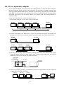
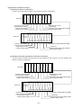
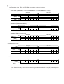
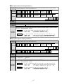
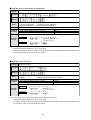
[9] Communication system using a JW10 link module (JW-25CM)
The JW-25CM can communicate with the JW10, by selecting data link master station function or remote
I/O master station function.
The JW-25CM is an option module, and up to 7 modules of JW-25CM (including other option modules)
can be mounted only to a basic rack panel.
(1) Data link master station
The system can communicate between a JW-25CM, a master station, and a JW10, slave station.
- This communication system can only communicate between a master and a slave station. It cannot
communicate between 2 slave stations.
JW-25CM
(master station)
JW300
JW-340CU
CM1
ON
RUN ↑
CM2
FLT PROTECT
JW10 (slave)
JW-25CM
USB
JW10 (slave)
JW10 (slave)
UNIT
NO.
L1
▲
PULL
PG/COMM1
電池交換
時期
This
battery
expires
L2
SHIELD
FG
電池の交換
は5分以内
に行ってく
ださい
Exchange
the battery
within
5minutes.
PG/COMM2
Slave station 63 sets max.
Shielded twisted pair cable
- Total expansion length and max. number of slave stations connected (JW10) are subject to the
settings of communication speed.
Communication speed
Total expansion length
Number of slave stations connected
76800 b i t s /s
Max . 500m
Max . 31
38400 b i t s /s
Max . 1k m
Max . 63
Items
Speceifications
Model name of slave station
JW-1324K/1424K/1624K (JW10 basic modules)
Number of transmission bytes per station
8 bytes each for receiving and sending.
3-16
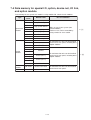
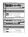
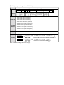
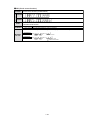
(2) Remote I/O master station
The system can communicate between a JW-25CM as a remote I/O master station and a JW10
basic module as a remote I/O slave station.
- Whether or not to synchronize a data exchange between a master and a slave station with operation
can be selected.
JW-25CM
(master station)
JW300
JW-340CU
CM1
ON
RUN ↑
CM2
FLT PROTECT
JW10 (slave)
JW-25CM
USB
JW10 (slave)
JW10 (slave)
UNIT
NO.
L1
▲
PULL
PG/COMM1
電池交換
時期
This
battery
expires
L2
SHIELD
FG
電池の交換
は5分以内
に行ってく
ださい
Exchange
the battery
within
5minutes.
PG/COMM2
Shielded twisted pair cable
Slave station 63 sets max.
- Total expansion length and max. number of slave stations connected (JW10) are subject to the
settings of communication speed.
Communication
speed
Data exchange
timing
Total expansion
length
No.of slave
stations connected
76800 b i t s /s
Sy n c h r o n o u s
/as y n c h r o n o u s
Max . 500m
Max . 31
Sy n c h r o n o u s
Max . 1k m
Max . 16
Asynchronous
Max . 1k m
Max . 63
38400 b i t s /s
Items
Speceifications
Mo d el n am e o f s l av e s t at i o n
J W-1324K /1424K /1624K (J W10 b as i c m o d u l es )
Nu m b er o f I/O points per station
Max. 60 points (36 for inputs, 24 for outputs)
3-17
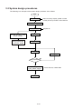
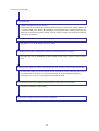
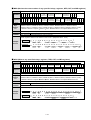
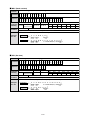
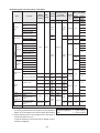
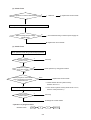
3-3 System design procedures
The following is an example of the system design procedure of the JW300.
Start
System design
Select of memory capacity (model of control
module) and set up number of I/O module etc.
Preparation of operation
Address allocation
Individual operation check
of each module
Ladder design
Wiring input/output
device with JW300
Programming
Register I/O
Debugging
Revise program
Trial operation
NG
OK
Save program,
modify ladder diagram
Run
3-18
Store in FD, HD, or flash ROM
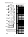
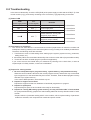
3-4 Precautions for system design
If an error occurs in the PLC, the whole system will report a fault.
In order to create a fail-safe system, we recommend preparing independent external protective circuits
for following functions, which may cause a breakdown of machine or injury to workers:
• Emergency stop circuit,
• Protection circuit,
• Operating circuit of high voltage device.
Also, be aware of the operation response time, as a PLC operates using cyclic processing.
To prevent mis-operation due to output signal of the output module soon after switching on power to the
JW300, connect in series the halt output for the JW300 in the following operation stand-by circuit.
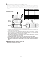
(1) In case of using AC power supply
85 to 264 VAC (JW-301PU)
85 to 132 VAC (JW-31PU)
85 to 264 VAC (JW-301PU)
85 to 132 VAC (JW-31PU)
JW300
Input module
- When the JW300 stops its operation, all
the output module indicate ON/OFF
condition just before stopping.
Note: When setting an output holding
address in the system memory,
all the output after the setting
address is retained and you can
reset the previously set address.
(only available when power is
supplied to the JW300.)
Output module
Operation
Emergency
preparation
stop
- Connecting the input module and output
module for lighting lamps in front of
emergency stop circuit makes it possible
to grasp the stop condition of devices.
JW300
halt output
MC
- Halt output
JW-301PU Relay output: 100/200 VAC,
30 VDC, 1A
JW-31PU Relay output: 100 VAC, 30
VDC, 1A
Thermal
MC switch
Output module
MS1
MS2
MS2
MS1
- Interlock circuit
Prepare external interlock circuit to
prevent reverse operation, damage of
machines and injury of workers.
Note: When DC output module is used
as a output module, use AC relay
and install its contact in the
emergency stop circuit.
3-19
(2) In case of using DC power supply
(24 VDC)
• Connecting an input module and output
module for lighting lamps in front of
emergency stop circuit makes it possible to
grasp the stop condition of devices.
0V
JW300
Input module
• When the JW300 stops its operation, all the
output module indicate ON/OFF condition just
before stopping.
Note: When setting an output holding
address in the system memory, all
the output after the setting address
is retained and you can reset the
previously set address.
(only available when power is
supplied to the JW300.)
Output module
Operation
Emergency preparation
stop
JW300
halt output
• Halt output (relay output 100/200 VAC, 30
VDC, 1A)
MC
Thermal
MC switch
Output module
MS1
• Interlock circuit
Prepare external interlock circuit to prevent
reverse operation, damage to machines and
injury of workers.
MS2
MS2
MS1
3-20
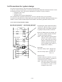
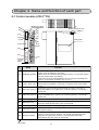
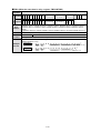
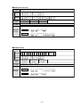
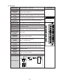
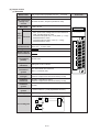
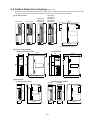
Chapter 4. Name and function of each part
4-1 Control module (JW-3**CU)
Model name label
(8)
(1)
(9)
←
O
F
F
(14)
PROTECT
AUTO LD
RESET
Module retention screw
(1pc.)
(2)
(3)
RUN
FLT
CM1
CM2
C
A
R
D
(10)
(4)
(5)
USB
MW
(7)
Rating plate
(6)
(11)
(12)
(15)
(16)
▲
PULL
PG/COMM1
電池交換
時期
This
battery
expires
(17)
Software
version
label
電池の交換
は5分以内
に行ってく
ださい
Exchange
the battery
within
5minutes.
(13)
PG/COMM2
Name
Function
Lights, blinks, and goes OFF, according to JW300 operating condition.
- Lights when the JW300 is operating.
- Blinks when the JW300 is being programmed by a connected support
tool (the JW300 stops calculating.)
- Goes OFF when the JW300 detects an error using its self-diagnosis
function. (Lights when a battery error occurs.)
Lights when detecting errors by self-diagnosis.
JW300 stops its operations. (However, it operates even when battery
is error.)
Lights when communicating with personal computer or the like, by
using PG/COMM1 port. Lights up in monitoring state by connecting a
support tool.
Lights when communicating with personal computer or the like, by
using PG/COMM2 port. Lights up in monitoring state by connecting a
support tool.
(1)
RUN lamp (green)
(2)
FAULT lamp (red)
(3)
CM1 lamp (yellow)
(4)
CM2 lamp (yellow)
(5)
USB lamp (yelow)
Lights when the JW300 is communicating through its USB port.
(6)
MW lamp (red)
Blinks when changing the program memory.
Goes OFF when special relay 7331 is turned ON.
(7)
CARD lamp
Lights when the JW300 is accessing a PC card.
(8)
PROTECT switch
Set prohibit (ON), enable (OFF) about writing to program memory
and system memory.
AUTO LD switch
Select a mode for the memory card
- When it is slid to the ON position, the JW300 automatically loads
programs and data from a memory card (compact flash card)
immediately after the power is turned ON.
(9)
Next page
4-1
Name
Function
(10)
RESET switch
Software reset
- If the calculation time for one scan is abnormally long, the JW300
may repeat a run and stop sequence. In this case, press the
RESET switch to change the JW300 to the program mode.
(11)
USB port *
A connector used to connect the JW300 to a USB port on a personal
computer. (USB1.1 compatible.)
(12) PG/COMM1 port *
A connector for connecting with device having Serial I/O port such as
(RS-232C / RS-422A)
support tool, personal computer. JW-311CU/312CU don’t have PG/
COMM2 port.
PG/COMM 2 port *
(13)
(RS-232C / RS-422A)
(14) Card cover
(15) PC card slot *
(16) Battery cover
(17)
Validity period label
on the battery
Insert a CF or SRAM card into the PC card slot.
Close the card cover to prevent the CF or SRAM card from falling
out. (Protection).
- The JW-311CU/321CU/331CU/341CU do not have a PC card slot
or card cover.
A battery module for memory backup is provided inside; opened and
closed when replacing battery. When delivered, the battery is not
connected to the JW300. Before using the JW300, make sure to
connect the battery assembly connector to the battery connecter on
the control module. Then clear (initialize) the memory inside the
JW300.
Indicates the period within which the battery (for memory back up)
for the control module should be functional. Write down the time to
replace the battery along with the conditions in which you are using
the control module.
* With cover
4-2
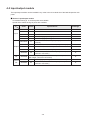
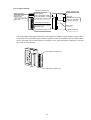
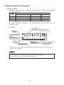
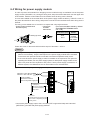
4-2 Power supply module
The power supply modules that can be used with the JW300 are as follows:
Model
name
Specification
Approved Approved
UL
CSA
JW-303PU *1 85 to 264 VAC. Power capacity: 5 VDC 4.5 A
JW-301PU *2 85 to 264 VAC. Power capacity: 5 VDC 3.5 A
JW-31PU
85 to 132 VAC. Power capacity: 5 VDC 3.5 A
JW-22PU
20.4 to 32 VDC. Power capacity: 5 VDC 3.5 A
O
O
*1: The JW-33PU power supply module for theJW20H/30H can also be used with the JW300.
*2: The JW-21PU power supply module for theJW20H/30H can also be used with the JW300.
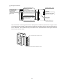
- When a power supply module is installed on an expansion rack panel, and if a power is supplied to
the power supply module on the basic rack panel without supplying power to the power supply
module on the expansion rack panel, the system detects as "input/output error" (#0160 = Error code
40) or "expansion power supply error" (#0160 = Error code 43). Make sure to supply power also to
the power supply module on the expansion rack panel.
- The power terminal block is equipped with a terminal block cover at delivery. Remove this cover
when you wire. After connecting, make sure to put the cover to the original position.
Module retention
screw
[1] JW-301PU/31PU/22PU
Module name
indication label
POWER
RUN
POWER lamp (green)
(Lights when power
is supplied)
Rating plate
Module
retention rib
Programmer retention
screw hole
RUN lamp (green)
Power supply terminal
block (with cover)
=> See next page
- Operating normally, lights ON
- Programming after connecting support tool: Blinking (PLC
stops operation)
- Detect errors by self-diagnosis function: Lights OFF (when
battery is error, lights ON.)
- The JW-301PU, 31PU, and 22PU are identical in shape.
4-3
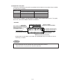
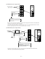
[Power supply terminal block]
This is a terminal block for connecting extended line of power supply, GND, halt output and the like.
JW-301PU
*1
L
POWER
INPUT
100-240 VAC
N
POWER
RUN
*5 Short bar
85 to 264 VAC
Power supply
input terminal
*2
GND (grounding)
terminal
SHORT
GND
HALT
OUTPUT
100-240 VAC
(24 VDC)
1A
JW-31PU
JW-22PU
(+)
POWER
INPUT
24 VDC
*1 L
POWER
INPUT
100-120 VAC
N
*5 Short bar
SHORT
*4
20.4 to 32 VDC
Power supply
input terminal
(—)
GND
HALT
OUTPUT
24 VDC
(100-240
VAC)
1A
*3
Halt output terminal
*2
GND (grounding)
terminal
*2
GND (grounding)
terminal
GND
HALT
OUTPUT
100-120 VAC
(24 VDC)
1A
*3
Halt output
terminal
85 to 132 VAC
Power supply input
terminal
*3
Halt output terminal
*1 Connect the power supply input of JW-301PU/31PU while paying attention to the L terminal (LIVE:
non-grounded side) and N terminal (NEUTRAL: grounded side).
*2 To prevent electric shock and noise error, be sure to separately prepare class-3 grounding.
*3 Be sure to incorporate the line to the external emergency stop circuit.
*4 As for DC input power supply, use power source of 20.4 to 32 VDC (ripple rate 20% or less;
however, ripple upper limit: 32 V or less, lower limit: 20.4 V or more).
*5 When testing insulation resistance or dielectric strength of the JW-301PU/31PU power supply
modules, be sure to remove the short bar connecting between the SHORT terminal and the GND
terminal. The power supply module has a serge absorber connected between the AC input line
and the SHORT terminal, as well as a short bar between the SHORT terminal and the GND
terminal at the time of shipment. If a test is carried out without removing the short bar, internal
elements of the module may be damaged due to overcurrent.
4-4
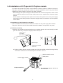
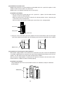
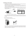
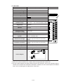
[2] JW-303PU
POWER lamp (green)
(Lights when power is supplied)
RUN lamp (green)
- Operating normally, lights ON
- Programming after connecting support tool : Blinking (PLC stops operation)
- Detect errors by self-diagnosis function : Lights OFF (when battery is error,
lights ON.)
Module retention screw
JW-303PU
POWER
RUN
増設ベースユニット
EXPANSION
RACK PANEL
Programmer retention
screw hole
Rack number label
Write rack number of
expansion rack panel.
Module insert guide
Rating plate
RACK NO.
L
POWER
INPUT
100∼240VAC
N
GND
HALT
OUTPUT
100∼240VAC
(24VAC)
1A
85 to 264VAC
Power supply input terminal
*1
GND (grounding terminal) *2
Module retention rib
Halt output terminal *3
Power supply terminal block (with cover)
*1: Connect the power supply input while paying attention to the terminal (LIVE: non-grounded
side) and N terminal (NEUTRAL : grounded side).
*2: To prevent electric shock and noise, error, be sure to separately prepare class-3 grounding.
Connect with internal between GND terminal.(Short bar having JW-301PU/31PU do not have
in JW-303PU).
*3: Be sure to incorporate the line to the external emergency stop circuit.
4-5
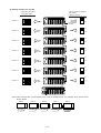
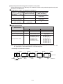
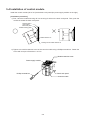
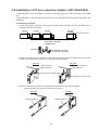
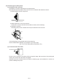
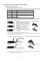
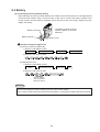
4-3 Input/output module
The input/output module can be installed in any order in the I/O module slot of the basic/expansion rack
panel.
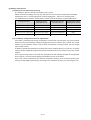
■ Kinds of input/output module
I/O modules having 8, 16, and 32 points are available.
Special I/O modules having 64 points are available.
Input
Output
I/O
Special
I/O
Model
name
Points
JW-203N
8
200/240 VAC
-
JW-211NA
16
100/120 VAC
O
JW-212NA
16
12/24 VDC
O
JW-214NA
16
12/24 VDC (high speed type)
O
JW-234N
32
O
JW-204SA
8
12/24 VDC (high speed type, connector connection)
250 VAC/30 VDC, 2A, relay output (separated
common)
JW-212SA
16
5/12/24 VDC, 0.5A, transistor output (sink output)
O
Specifications
Applied CE
markings
-
JW-213SA
16
100/200 VAC, 0.5A, triac output
O
JW-214SA
16
250 VAC/30 VDC, 2A, relay output
O
JW-232S
32
5/12/24 VDC, 0.1A, transistor output (sink output,
connector connection)
O
JW-232M
12/24 VDC, input 16 points, transistor 16 points output, 0.1A
(sink output, connector connection)
O
JW-264N
64
24 VDC (high speed type, connector connection)
O
JW-262S
64
5/12/24 VDC, 0.1A transistor output (sink output,
connector connection)
O
4-6
[1] 8/16 points module
Current consumption mark
Module name label
A
Input/output signal
indication lamp
Lights when input/output
signal "ON"
0 1 2 3 4 5 6 7
B
0 1 2 3 4 5 6 7
Indications the current
consumption of
5 VDC input/output module.
(One label: Approx. 100 mA)
Terminal block retention screw
Module retention screw
Connector
Connects with connector
for the I/O slot of basic/
expansion rack panel.
Input/output terminal block
Connects external lines of
input/output devices. (Quick
disconnect type)
Terminal block retention screw
Rating plate
Module retention rib
The terminal block connecting external lines in 8/16 points I/O module is quick-disconnect type. Loosen
2 mounting screws provided in upper and lower positions of the terminal block, then the terminal block
can be detached. And a malfunctioning I/O module can be replaced without removing the external
lines from the terminal block.
Terminal block retention screw
Terminal block retention screw
4-7
Chapter 4. Name and function of each part
4-1 Control module (JW-3**CU)
Model name label
(8)
(1)
(9)
←
O
F
F
(14)
PROTECT
AUTO LD
RESET
Module retention screw
(1pc.)
(2)
(3)
RUN
FLT
CM1
CM2
C
A
R
D
(10)
(4)
(5)
USB
MW
(7)
Rating plate
(6)
(11)
(12)
(15)
(16)
▲
PULL
PG/COMM1
電池交換
時期
This
battery
expires
(17)
Software
version
label
電池の交換
は5分以内
に行ってく
ださい
Exchange
the battery
within
5minutes.
(13)
PG/COMM2
Name
Function
Lights, blinks, and goes OFF, according to JW300 operating condition.
- Lights when the JW300 is operating.
- Blinks when the JW300 is being programmed by a connected support
tool (the JW300 stops calculating.)
- Goes OFF when the JW300 detects an error using its self-diagnosis
function. (Lights when a battery error occurs.)
Lights when detecting errors by self-diagnosis.
JW300 stops its operations. (However, it operates even when battery
is error.)
Lights when communicating with personal computer or the like, by
using PG/COMM1 port. Lights up in monitoring state by connecting a
support tool.
Lights when communicating with personal computer or the like, by
using PG/COMM2 port. Lights up in monitoring state by connecting a
support tool.
(1)
RUN lamp (green)
(2)
FAULT lamp (red)
(3)
CM1 lamp (yellow)
(4)
CM2 lamp (yellow)
(5)
USB lamp (yelow)
Lights when the JW300 is communicating through its USB port.
(6)
MW lamp (red)
Blinks when changing the program memory.
Goes OFF when special relay 7331 is turned ON.
(7)
CARD lamp
Lights when the JW300 is accessing a PC card.
(8)
PROTECT switch
Set prohibit (ON), enable (OFF) about writing to program memory
and system memory.
AUTO LD switch
Select a mode for the memory card
- When it is slid to the ON position, the JW300 automatically loads
programs and data from a memory card (compact flash card)
immediately after the power is turned ON.
(9)
Next page
4-1
Name
Function
(10)
RESET switch
Software reset
- If the calculation time for one scan is abnormally long, the JW300
may repeat a run and stop sequence. In this case, press the
RESET switch to change the JW300 to the program mode.
(11)
USB port *
A connector used to connect the JW300 to a USB port on a personal
computer. (USB1.1 compatible.)
(12) PG/COMM1 port *
A connector for connecting with device having Serial I/O port such as
(RS-232C / RS-422A)
support tool, personal computer. JW-311CU/312CU don’t have PG/
COMM2 port.
PG/COMM 2 port *
(13)
(RS-232C / RS-422A)
(14) Card cover
(15) PC card slot *
(16) Battery cover
(17)
Validity period label
on the battery
Insert a CF or SRAM card into the PC card slot.
Close the card cover to prevent the CF or SRAM card from falling
out. (Protection).
- The JW-311CU/321CU/331CU/341CU do not have a PC card slot
or card cover.
A battery module for memory backup is provided inside; opened and
closed when replacing battery. When delivered, the battery is not
connected to the JW300. Before using the JW300, make sure to
connect the battery assembly connector to the battery connecter on
the control module. Then clear (initialize) the memory inside the
JW300.
Indicates the period within which the battery (for memory back up)
for the control module should be functional. Write down the time to
replace the battery along with the conditions in which you are using
the control module.
* With cover
4-2
4-2 Power supply module
The power supply modules that can be used with the JW300 are as follows:
Model
name
Specification
Approved Approved
UL
CSA
JW-303PU *1 85 to 264 VAC. Power capacity: 5 VDC 4.5 A
JW-301PU *2 85 to 264 VAC. Power capacity: 5 VDC 3.5 A
JW-31PU
85 to 132 VAC. Power capacity: 5 VDC 3.5 A
JW-22PU
20.4 to 32 VDC. Power capacity: 5 VDC 3.5 A
O
O
*1: The JW-33PU power supply module for theJW20H/30H can also be used with the JW300.
*2: The JW-21PU power supply module for theJW20H/30H can also be used with the JW300.
- When a power supply module is installed on an expansion rack panel, and if a power is supplied to
the power supply module on the basic rack panel without supplying power to the power supply
module on the expansion rack panel, the system detects as "input/output error" (#0160 = Error code
40) or "expansion power supply error" (#0160 = Error code 43). Make sure to supply power also to
the power supply module on the expansion rack panel.
- The power terminal block is equipped with a terminal block cover at delivery. Remove this cover
when you wire. After connecting, make sure to put the cover to the original position.
Module retention
screw
[1] JW-301PU/31PU/22PU
Module name
indication label
POWER
RUN
POWER lamp (green)
(Lights when power
is supplied)
Rating plate
Module
retention rib
Programmer retention
screw hole
RUN lamp (green)
Power supply terminal
block (with cover)
=> See next page
- Operating normally, lights ON
- Programming after connecting support tool: Blinking (PLC
stops operation)
- Detect errors by self-diagnosis function: Lights OFF (when
battery is error, lights ON.)
- The JW-301PU, 31PU, and 22PU are identical in shape.
4-3
[Power supply terminal block]
This is a terminal block for connecting extended line of power supply, GND, halt output and the like.
JW-301PU
*1
L
POWER
INPUT
100-240 VAC
N
POWER
RUN
*5 Short bar
85 to 264 VAC
Power supply
input terminal
*2
GND (grounding)
terminal
SHORT
GND
HALT
OUTPUT
100-240 VAC
(24 VDC)
1A
JW-31PU
JW-22PU
(+)
POWER
INPUT
24 VDC
*1 L
POWER
INPUT
100-120 VAC
N
*5 Short bar
SHORT
*4
20.4 to 32 VDC
Power supply
input terminal
(—)
GND
HALT
OUTPUT
24 VDC
(100-240
VAC)
1A
*3
Halt output terminal
*2
GND (grounding)
terminal
*2
GND (grounding)
terminal
GND
HALT
OUTPUT
100-120 VAC
(24 VDC)
1A
*3
Halt output
terminal
85 to 132 VAC
Power supply input
terminal
*3
Halt output terminal
*1 Connect the power supply input of JW-301PU/31PU while paying attention to the L terminal (LIVE:
non-grounded side) and N terminal (NEUTRAL: grounded side).
*2 To prevent electric shock and noise error, be sure to separately prepare class-3 grounding.
*3 Be sure to incorporate the line to the external emergency stop circuit.
*4 As for DC input power supply, use power source of 20.4 to 32 VDC (ripple rate 20% or less;
however, ripple upper limit: 32 V or less, lower limit: 20.4 V or more).
*5 When testing insulation resistance or dielectric strength of the JW-301PU/31PU power supply
modules, be sure to remove the short bar connecting between the SHORT terminal and the GND
terminal. The power supply module has a serge absorber connected between the AC input line
and the SHORT terminal, as well as a short bar between the SHORT terminal and the GND
terminal at the time of shipment. If a test is carried out without removing the short bar, internal
elements of the module may be damaged due to overcurrent.
4-4
[2] JW-303PU
POWER lamp (green)
(Lights when power is supplied)
RUN lamp (green)
- Operating normally, lights ON
- Programming after connecting support tool : Blinking (PLC stops operation)
- Detect errors by self-diagnosis function : Lights OFF (when battery is error,
lights ON.)
Module retention screw
JW-303PU
POWER
RUN
増設ベースユニット
EXPANSION
RACK PANEL
Programmer retention
screw hole
Rack number label
Write rack number of
expansion rack panel.
Module insert guide
Rating plate
RACK NO.
L
POWER
INPUT
100∼240VAC
N
GND
HALT
OUTPUT
100∼240VAC
(24VAC)
1A
85 to 264VAC
Power supply input terminal
*1
GND (grounding terminal) *2
Module retention rib
Halt output terminal *3
Power supply terminal block (with cover)
*1: Connect the power supply input while paying attention to the terminal (LIVE: non-grounded
side) and N terminal (NEUTRAL : grounded side).
*2: To prevent electric shock and noise, error, be sure to separately prepare class-3 grounding.
Connect with internal between GND terminal.(Short bar having JW-301PU/31PU do not have
in JW-303PU).
*3: Be sure to incorporate the line to the external emergency stop circuit.
4-5
4-3 Input/output module
The input/output module can be installed in any order in the I/O module slot of the basic/expansion rack
panel.
■ Kinds of input/output module
I/O modules having 8, 16, and 32 points are available.
Special I/O modules having 64 points are available.
Input
Output
I/O
Special
I/O
Model
name
Points
JW-203N
8
200/240 VAC
-
JW-211NA
16
100/120 VAC
O
JW-212NA
16
12/24 VDC
O
JW-214NA
16
12/24 VDC (high speed type)
O
JW-234N
32
O
JW-204SA
8
12/24 VDC (high speed type, connector connection)
250 VAC/30 VDC, 2A, relay output (separated
common)
JW-212SA
16
5/12/24 VDC, 0.5A, transistor output (sink output)
O
JW-213SA
16
100/200 VAC, 0.5A, triac output
O
JW-214SA
16
250 VAC/30 VDC, 2A, relay output
O
JW-232S
32
5/12/24 VDC, 0.1A, transistor output (sink output,
connector connection)
O
JW-232M
Specifications
12/24 VDC, input 16 points, transistor 16 points output, 0.1A
(sink output, connector connection)
Applied CE
markings
-
O
JW-264N
64
24 VDC (high speed type, connector connection)
O
JW-262S
64
5/12/24 VDC, 0.1A transistor output (sink output,
connector connection)
O
4-6
[1] 8/16 points module
Current consumption mark
Module name label
A
Input/output signal
indication lamp
Lights when input/output
signal "ON"
0 1 2 3 4 5 6 7
B
0 1 2 3 4 5 6 7
Indications the current
consumption of
5 VDC input/output module.
(One label: Approx. 100 mA)
Terminal block retention screw
Module retention screw
Connector
Connects with connector
for the I/O slot of basic/
expansion rack panel.
Input/output terminal block
Connects external lines of
input/output devices. (Quick
disconnect type)
Terminal block retention screw
Rating plate
Module retention rib
The terminal block connecting external lines in 8/16 points I/O module is quick-disconnect type. Loosen
2 mounting screws provided in upper and lower positions of the terminal block, then the terminal block
can be detached. And a malfunctioning I/O module can be replaced without removing the external
lines from the terminal block.
Terminal block retention screw
Terminal block retention screw
4-7
[2] 32 points module
Current consumption mark
Module name label
A
Input/output signal
indication lamp
0 1 2 3 4 5 6 7
B
0 1 2 3 4 5 6 7
C
Module retention screw
Indication of the current
consumption of 5 VDC in
input/output module.
(One label: Approx. 100 mA)
Connector
0 1 2 3 4 5 6 7
D
0 1 2 3 4 5 6 7
Lights when input/output
signal is "ON"
Connects with connector
for the I/O slot of basic/
expansion rack panel.
Connector retention screw hole
I/O connector
Connects connector which is
connected to external lines
from input/output devices.
Rating plate
Terminal block retention
screw hole
Module retention rib
[Pin No. of I/O connector and signal name]
Signal name
Signal name
Pin
No. JW-234N JW-232S JW-232M
1B COM.AB Vacant COM.AB
2B Vacant COM.AB(-) Vacant
3B
A−1
4B
A−3
5B
A−5
6B
A−7
7B
B−1
8B
B−3
9B
B−5
10B
B−7
11B
C−1
12B
C−3
13B
C−5
14B
C−7
15B
D−1
16B
D−3
17B
D−5
18B
D−7
19B Vacant Vacant Vacant
20B COM.CD COM.CD(-) COM.CD(-)
Pin
JW-232M JW-232S JW-234N No.
COM.AB Vacant COM.AB 1A
Vacant COM.AB(-) Vacant 2A
3A
4A
5A
6A
7A
8A
9A
10A
11A
12A
13A
14A
15A
16A
17A
18A
19A
COM.CD(-) COM.CD(-) COM.CD 20A
A−0
A−2
A−4
A−6
B−0
B−2
B−4
B−6
C−0
C−2
C−4
C−6
D−0
D−2
D−4
D−6
Vacant Vacant Vacant
4-8
[3] 64 points module
Current consumption mark
Module retention screw
Fuse LED *1
(Only JW-262S)
Module No. switch
Module name indication label
01234567
Input/output signal indication lamp
Indicating lamp
selector switch
A
B
C
D
Module insert guide
Connector
FUSE
UNIT
NO.
2 1
CN
CN2
CN1
1 : The first half 32 points
2 : The second half 32 points
Rating plate
Connector retention
screw hole
*2
Connector CN2 for I/O (the second half)
Connector CN1 for I/O (the first half)
*2
Module retention rib
Connector retention
screw hole
*1 The fuse LED (JW-262S only) lights up (red) when the blown fuse or when the load power supply is
turned OFF. When the connector CN1 or CN2 is not used (not connected), power supply is not applied
to line (+) and COM (–), and hence the fuse LED lights (red). (It has, however, no effect on the output
operation of the operating connector side.)
In this case, by connecting the furnished connector to an idle connector and applying power supply
between line (+) and COM (–), it prevents from lighting of fuse LED due to idle connector.
*2 Pin No. of connector CN1, CN2 and signal name
CN1 (The first half
32 points)
Signal name
CN1
Signal name
Pin
No. JW-264N JW-262S
Pin
JW-264N JW-262S No.
COM.1 Power supply 1 (+) 1A
Vacant COM.1 (-) 2A
3A
A−0
4A
A−2
5A
A−4
6A
A−6
7A
B−0
8A
B−2
9A
B−4
10A
B−6
11A
C−0
12A
C−2
13A
C−4
14A
C−6
15A
D−0
16A
D−2
17A
D−4
18A
D−6
Vacant COM.1 (-) 19A
COM.1 Power supply 1 (+) 20A
- Pin number 1A and 20A, and
1B and 20B of JW-264N are
respectively connected inside.
CN2 (The second
half 32 points)
Signal name
CN2
1B COM.1 Power supply 1 (+)
2B Vacant COM.1 (-)
3B
A−1
4B
A−3
5B
A−5
6B
A−7
7B
B−1
8B
B−3
9B
B−5
10B
B−7
11B
C−1
12B
C−3
13B
C−5
14B
C−7
15B
D−1
16B
D−3
17B
D−5
18B
D−7
19B Vacant COM.1 (-)
20B COM.1 Power supply 1 (+)
- Pin number 1A and 19A,
2A and 20B, 1B and 19B,
and 2B and 20B of JW-262S
are respectively connected
insides.
Signal name
Pin
No. JW-264N JW-262S
Pin
JW-264N JW-262S No.
COM.2 Power supply 2 (+) 1A
Vacant COM.2 (-) 2A
3A
A−0
4A
A−2
5A
A−4
6A
A−6
7A
B−0
8A
B−2
9A
B−4
10A
B−6
11A
C−0
12A
C−2
13A
C−4
14A
C−6
15A
D−0
16A
D−2
17A
D−4
18A
D−6
Vacant COM.2 (-) 19A
COM.2 Power supply 2 (+) 20A
1B COM.2 Power supply 2 (+)
2B Vacant COM.2 (-)
3B
A−1
4B
A−3
5B
A−5
6B
A−7
7B
B−1
8B
B−3
9B
B−5
10B
B−7
11B
C−1
12B
C−3
13B
C−5
14B
C−7
15B
D−1
16B
D−3
17B
D−5
18B
D−7
19B Vacant COM.2 (-)
20B COM.2 Power supply 2 (+)
- Pin number 1A and 19A,
2A and 20A, 1B and 19B,
and 2B and 20B of JW-262S
are respectively connected
insides.
- Pin number 1A and 20A, and
1B and 20B of JW-264N are
respectively connected inside.
4-9
Relation with relay number
=> See A-1
4-4 Basic/expansion rack panel
[1] Basic rack panel
Three types of basic rack panels are provided, with variations in the number of slots available for
connecting I/O modules.
Number of slots
Model
name
For power supply module
For control module
For I/O module
JW-314KB
1
1
4
JW-316KB
1
1
6
JW-318KB
1
1
8
In the slot for I/O module, I/O, special I/O, I/O link, and option module, device net, and I/O link can be
connected in mixture.
- JW-318KB
Slot I/O module
Fitting I/O / special I/O / option / device net /
I/O link module
Module retention screw hole
Fitting hole
For fitting onto
control panel
Slot for power supply module
For fitting power supply
module
5V terminal block
For supplying 5 VDC to the
next expansion pack panel
Fitting hole
For fitting onto
control panel
Slot control module
For fitting control module
Module retention rib
inserting hole
When fitting module, insert
module retention
I/O expansion connector (OUT)
Connect an I/O expansion
cable or JW-31EA I/O bus
expansion adapter.
- Compared with the JW-318KB, the JW-314KB and JW-316KB differ only in the number of slots
for connecting I/O modules.
Note
- Put a connector cover on unused slots to prevent dust from entering.
Connector covers are put on each slot when delivered.
4-10
[2] Expansion rack panel
Three types of expansion rack panels are provided, with variations in the number of slots available
for connecting I/O modules.
Model name
No. of slot
For power supply module
For I/O module
JW-34ZB
1
4
JW-36ZB
1
6
JW-38ZB
1
8
In the slot for I/O module, I/O and special I/O module can be connected in mixture. The option,
device net, and I/O link module cannot be installed on it.
- JW-38ZB
Slot for power supply module
Fitting hole
Rack number switch
Setting an order of the rack for
allocating the address
(Set condition at delivery:1)
Module retention hole
Slot for I/O module
Fitting I/O / Special I/O module
I/O expansion connector (OUT)
I/O expansion connector (IN)
Connect an I/O expansion
cable on JW-32EA I/O bus
expansion adapter.
Module retention rib inserting hole
5V terminal block
Connect 5 VDC cable from
basic/expansion rack panel
- Compared with the JW-38ZB, the JW-34ZB and JW-36ZB differ only in the number of slots for
connecting I/O modules.
Note
- Put a connector cover on unused slots to prevent dust from entering.
Connector covers are put on each slot when delivered.
4-11
[3] Rack No. (expansion rack panel)
(1) In case of not using I/O bus expansion adapter
System can be configured with up to 4 racks, and each rack ID number will be specified by the
settings of the rack number switch on the expansion rack panel(JW-34ZB/36ZB/38ZB).
The basic rack panel is fixed to rack No. 0.
Rack No. switch
Rack No. 3
123
Rack No. 2
123
Rack No. 1
123
▲
It is a table registration error (70) or table verification error (60) when the rack number switch is set
as follows 1 to 3, and the JW300 does not operate.
1. There are plural ON settings.
123
[Ex.]
2. All setting of the rack no. is OFF.
123
3. Rack numbers are duplicated with other expansion rack panel.
The error code is stored in the system memory #0160.
The shipping setting of rack number switch is "1: switch 1 is ON."
4-12
(2) In case of using I/O bus expansion adapter
System can be configured with max. 8 racks when an expansion rack panel, JW-34ZB/36ZB/
38ZB, is connected with an I/O bus expansion adapter, JW-32EA. Each rack panel ID number will
be defined by combination of settings for the rack number switches on the expansion rack panel
and the JW-32EA.
The basic rack panel is fixed to rack No. 0.
Rack No. switch of
expansion rack panel
Rack No.
Rack No. switch of I/O bus
expansion adapter (JW-32EA)
1
ON for only
No. 1
123
1-3 side
2
ON for only
No. 2
123
1-3 side
3
ON for only
No. 3
123
1-3 side
4
OFF for all
123
4-7 side
5
ON for only
No. 1
123
4-7 side
6
ON for only
No. 2
123
4-7 side
7
ON for only
No. 3
123
4-7 side
4-7
1-3
4-7
1-3
4-7
1-3
4-7
1-3
4-7
1-3
4-7
1-3
4-7
1-3
It is a table registration error (70) or table verification error (60) when the rack number switch is set
as follows 1, 2, and the JW300 does not operate.
1. There are plural ON settings.
123
[Ex.]
2. Rack numbers are duplicated with other expansion rack panel.
The shipping setting of rack number switch is "1 : switch 1 is ON," and that of I/O bus expansion
adapter is "1 to 3" side.
For I/O bus expansion adapter, see page 4-16 to 18.
4-13
(3) Setting example for rack No.
I/O bus expansion adapter
(JW-32EA)
Rack No. switch
Expansion rack panel
Rack No. switch
4-7
123
Rack No. 7
Termination
connector
4-7
123
Rack No. 6
1-3
4-7
123
Rack No. 5
1-3
4-7
123
Rack No. 4
1-3
4-7
123
Rack No. 3
1-3
4-7
123
Rack No. 2
1-3
4-7
123
Rack No. 1
1-3
1-3
JW-340CU
←
O
F
F
PROTECT
INIT
RESET
RUN
FLT
CM1
CM2
C
A
R
D
USB
SV
▲
PULL
PG/COMM1
電池交換
時期
This
battery
expires
電池の交換
は5分以内
に行ってく
ださい
Exchange
the battery
within
5minutes.
PG/COMM2
Note: Rack numbers are not necessarily set in order of added timings. For example, they can be set as
shown below.
Rack 0
Rack 1
Rack 2
Rack 4
Rack 3
JW-31EA
JW-32EA
JW-32EA
JW-32EA
JW-32EA
4-14
[4] Important points when using basic /expansion rack panels
System specifications can be defined by the combination of basic rack panel and expansion rack panel
as shown in the table below.
■ Combinations of basic and expansion rack panels
Expansion
rack panel
Basic rack
JW-314KB/316KB/318KB
panel JW-314KB/36KB/318KB
(Without JW-31EA)
(With JW-31EA)
None
A
Unable to use in
combination
JW-34ZB/36ZB/38ZB
(Without JW-32EA)
B
Unable to use in
combination
JW-34ZB/36ZB/38ZB
(With JW-32EA)
Unable to use in
combination
C
■ System specifications
Combinations of basic/expansion rack panels (as above)
Specifications
A
B
C
Max. number of racks
1
4
8
Total expansion length
-
14 m
50 m
High
speed
Conventional speed
High speed
Option bus speed (Note)
JW-203EC (30 cm)
JW-207EC (70 cm)
JW-22EC (2 m)
JW-25EC (5 m)
JW-210EC (10 m)
-
I/O expansion cable
JW-05EC (50 cm)
JW-1EC (1 m)
JW-3EC (3 m)
JW-10EC (10 m)
JW-20EC (20 m)
JW-30EC (30 m)
JW-50EC (50 m)
Note: Option bus speed is data exchange speed between an option module and a control module, and
the “high speed” is twice faster than the “conventional speed.”
- An example of combination C above
JW-31EA
JW-318KB
JW-32EA
JW-38ZB
JW-32EA
JW-38ZB
JW-36ZB
JW-32EA
JW-32EA
JW-34ZB
Total 5 racks
JW-30EC
(30 m)
JW-22CM
JW-**CU
High speed
JW-10EC
(10 m)
4-15
JW-3EC
(3 m)
JW-1EC
(1 m)
Total 44 m
4-5 I/O bus expansion adapter
I/O bus expansion adapter for the JW30H has two available models, the JW-31EA and the JW-32EA,
that are used to link signals sent from each rack panel. The JW-31EA is installed in the basic rack
panel JW-314KB/316KB/318KB, while the JW-32EA is installed in the expansion rack panel JW-34ZB/
36ZB/38ZB. The I/O expansion cable, JW-05EC/1EC/3EC/10EC/20EC/30EC/50EC, is used to connect
rack panels (install the I/O bus expansion adapter). (See page 6-18 for connection method of I/O
expansion cable).
I/O bus expansion adapter is used for the following cases:
1) In the case of using min. 5 racks (max. 8) on the rack panel
JW-31EA
JW-32EA
JW-32EA
JW-32EA
Rack 1
Rack 2
Rack 3
Rack 0
JW-32EA
Rack 7
Max. 8 racks on the rack panel
2) In the case of keeping a min. distance of 11 m (max. 50 m) between rack panels, or keeping a min.
distance of 15 m (max. 50 m) between the basic rack panel and the last expansion rack panel:
JW-31EA
JW-32EA
Max. distance of 50 m between the rack panels
JW-31EA
JW-32EA
JW-32EA
JW-32EA
Max. 50m total cable length
3) In the case of operating a high-speed data exchange (twice faster than without using I/O bus
expansion adapter) between an option module, such as JW-21CM and JW-22CM, and a control
module on a system that needs an expansion rack panel:
Option module
Control module
JW-31EA
JW-32EA
High-speed data exchange
4) In the case of creating, changing, or monitoring a program on the expansion rack panel side using
a support tool (JW-300SP, JW-15PG).
JW-31EA
JW-32EA
JW-32EA
JW-32EA
JW-300SP
4-16
[1] JW-31EA
Module fixing screw
(1)
Rating plate
Module fixing screw
(1) I/O expansion connector
Connect between the I/O expansion connectors (IN) of JW-32EA using I/O expansion cables.
[2] JW-32EA
Module fixing screw
(1)
(2)
(3)
Rating plate
(4)
(5)
Module fixing screw
(1) Connector for support tool connection (EA-PG port)
Connecting a support tool (JW-300SP, JW-15PG), such as a hand-held programmer, enables
creating/changing/monitoring program on the expansion rack panel that is max. 50 meters
away.
This connector can be used for communication with equipment that has serial I/O ports, such
as a personal computer. This connector is seen as Communication Port 3 in the JW300 system.
(2) I/O expansion connector (IN)
Connect this connector and an I/O expansion connector (OUT) on the JW-31EAs or the JW32EAs (a front rack) using an I/O expansion cable.
(3) Rack No. switch
Set rack numbers on the mounted rack panel.
Rack No.
4-7: Racks 4 to 7
1-3: Racks 1 to 3 (setting at delivery)
Rack ID numbers are determined by combined setting of this rack number switches and ones
on the expansion rack panel, JW-34ZB/36ZB/38ZB. See page 4-13 for details.
(4) I/O expansion connector (OUT)
Connect this connector and an I/O expansion connector (IN) on the JW-32EA (the next rack)
using an I/O expansion cable.
(5) Termination connector insert
Insert a termination connector when a mounted expansion rack panel is at the end of the
system. One each termination connector is supplied with each JW-31EA.
4-17
Notes
- Only one support tool (JW-300SP, JW-15PG) can be connected to the JW-32EA.
[Ex.]
Control module
JW-31EA
JW-32EA
JW-32EA
Support tool
Support tool
- With the JW300 system, while a support tool (JW-300SP, JW-15PG) is connected to the
control module, another support tool can be connected to the JW-32EA. (The JW30H
cannot connect to a support tool under this condition.)
[Ex.]
Control module
JW-31EA
JW-32EA
JW-32EA
Support tool
Support tool
4-18
[3] 64 points module
Current consumption mark
Module retention screw
Fuse LED *1
(Only JW-262S)
Module No. switch
Module name indication label
01234567
Input/output signal indication lamp
Indicating lamp
selector switch
A
B
C
D
Module insert guide
Connector
FUSE
UNIT
NO.
2 1
CN
CN2
CN1
1 : The first half 32 points
2 : The second half 32 points
Rating plate
Connector retention
screw hole
*2
Connector CN2 for I/O (the second half)
Connector CN1 for I/O (the first half)
*2
Module retention rib
Connector retention
screw hole
*1 The fuse LED (JW-262S only) lights up (red) when the blown fuse or when the load power supply is
turned OFF. When the connector CN1 or CN2 is not used (not connected), power supply is not applied
to line (+) and COM (–), and hence the fuse LED lights (red). (It has, however, no effect on the output
operation of the operating connector side.)
In this case, by connecting the furnished connector to an idle connector and applying power supply
between line (+) and COM (–), it prevents from lighting of fuse LED due to idle connector.
*2 Pin No. of connector CN1, CN2 and signal name
CN1 (The first half
32 points)
Signal name
CN1
Signal name
Pin
No. JW-264N JW-262S
Pin
JW-264N JW-262S No.
COM.1 Power supply 1 (+) 1A
Vacant COM.1 (-) 2A
3A
A−0
4A
A−2
5A
A−4
6A
A−6
7A
B−0
8A
B−2
9A
B−4
10A
B−6
11A
C−0
12A
C−2
13A
C−4
14A
C−6
15A
D−0
16A
D−2
17A
D−4
18A
D−6
Vacant COM.1 (-) 19A
COM.1 Power supply 1 (+) 20A
- Pin number 1A and 20A, and
1B and 20B of JW-264N are
respectively connected inside.
CN2 (The second
half 32 points)
Signal name
CN2
1B COM.1 Power supply 1 (+)
2B Vacant COM.1 (-)
3B
A−1
4B
A−3
5B
A−5
6B
A−7
7B
B−1
8B
B−3
9B
B−5
10B
B−7
11B
C−1
12B
C−3
13B
C−5
14B
C−7
15B
D−1
16B
D−3
17B
D−5
18B
D−7
19B Vacant COM.1 (-)
20B COM.1 Power supply 1 (+)
- Pin number 1A and 19A,
2A and 20B, 1B and 19B,
and 2B and 20B of JW-262S
are respectively connected
insides.
Signal name
Pin
No. JW-264N JW-262S
Pin
JW-264N JW-262S No.
COM.2 Power supply 2 (+) 1A
Vacant COM.2 (-) 2A
3A
A−0
4A
A−2
5A
A−4
6A
A−6
7A
B−0
8A
B−2
9A
B−4
10A
B−6
11A
C−0
12A
C−2
13A
C−4
14A
C−6
15A
D−0
16A
D−2
17A
D−4
18A
D−6
Vacant COM.2 (-) 19A
COM.2 Power supply 2 (+) 20A
1B COM.2 Power supply 2 (+)
2B Vacant COM.2 (-)
3B
A−1
4B
A−3
5B
A−5
6B
A−7
7B
B−1
8B
B−3
9B
B−5
10B
B−7
11B
C−1
12B
C−3
13B
C−5
14B
C−7
15B
D−1
16B
D−3
17B
D−5
18B
D−7
19B Vacant COM.2 (-)
20B COM.2 Power supply 2 (+)
- Pin number 1A and 19A,
2A and 20A, 1B and 19B,
and 2B and 20B of JW-262S
are respectively connected
insides.
- Pin number 1A and 20A, and
1B and 20B of JW-264N are
respectively connected inside.
4-9
Relation with relay number
=> See A-1
4-4 Basic/expansion rack panel
[1] Basic rack panel
Three types of basic rack panels are provided, with variations in the number of slots available for
connecting I/O modules.
Number of slots
Model
name
For power supply module
For control module
For I/O module
JW-314KB
1
1
4
JW-316KB
1
1
6
JW-318KB
1
1
8
In the slot for I/O module, I/O, special I/O, I/O link, and option module, device net, and I/O link can be
connected in mixture.
- JW-318KB
Slot I/O module
Fitting I/O / special I/O / option / device net /
I/O link module
Module retention screw hole
Fitting hole
For fitting onto
control panel
Slot for power supply module
For fitting power supply
module
5V terminal block
For supplying 5 VDC to the
next expansion pack panel
Fitting hole
For fitting onto
control panel
Slot control module
For fitting control module
Module retention rib
inserting hole
When fitting module, insert
module retention
I/O expansion connector (OUT)
Connect an I/O expansion
cable or JW-31EA I/O bus
expansion adapter.
- Compared with the JW-318KB, the JW-314KB and JW-316KB differ only in the number of slots
for connecting I/O modules.
Note
- Put a connector cover on unused slots to prevent dust from entering.
Connector covers are put on each slot when delivered.
4-10
[2] Expansion rack panel
Three types of expansion rack panels are provided, with variations in the number of slots available
for connecting I/O modules.
Model name
No. of slot
For power supply module
For I/O module
JW-34ZB
1
4
JW-36ZB
1
6
JW-38ZB
1
8
In the slot for I/O module, I/O and special I/O module can be connected in mixture. The option,
device net, and I/O link module cannot be installed on it.
- JW-38ZB
Slot for power supply module
Fitting hole
Rack number switch
Setting an order of the rack for
allocating the address
(Set condition at delivery:1)
Module retention hole
Slot for I/O module
Fitting I/O / Special I/O module
I/O expansion connector (OUT)
I/O expansion connector (IN)
Connect an I/O expansion
cable on JW-32EA I/O bus
expansion adapter.
Module retention rib inserting hole
5V terminal block
Connect 5 VDC cable from
basic/expansion rack panel
- Compared with the JW-38ZB, the JW-34ZB and JW-36ZB differ only in the number of slots for
connecting I/O modules.
Note
- Put a connector cover on unused slots to prevent dust from entering.
Connector covers are put on each slot when delivered.
4-11
[3] Rack No. (expansion rack panel)
(1) In case of not using I/O bus expansion adapter
System can be configured with up to 4 racks, and each rack ID number will be specified by the
settings of the rack number switch on the expansion rack panel(JW-34ZB/36ZB/38ZB).
The basic rack panel is fixed to rack No. 0.
Rack No. switch
Rack No. 3
123
Rack No. 2
123
Rack No. 1
123
▲
It is a table registration error (70) or table verification error (60) when the rack number switch is set
as follows 1 to 3, and the JW300 does not operate.
1. There are plural ON settings.
123
[Ex.]
2. All setting of the rack no. is OFF.
123
3. Rack numbers are duplicated with other expansion rack panel.
The error code is stored in the system memory #0160.
The shipping setting of rack number switch is "1: switch 1 is ON."
4-12
(2) In case of using I/O bus expansion adapter
System can be configured with max. 8 racks when an expansion rack panel, JW-34ZB/36ZB/
38ZB, is connected with an I/O bus expansion adapter, JW-32EA. Each rack panel ID number will
be defined by combination of settings for the rack number switches on the expansion rack panel
and the JW-32EA.
The basic rack panel is fixed to rack No. 0.
Rack No. switch of
expansion rack panel
Rack No.
Rack No. switch of I/O bus
expansion adapter (JW-32EA)
1
ON for only
No. 1
123
1-3 side
2
ON for only
No. 2
123
1-3 side
3
ON for only
No. 3
123
1-3 side
4
OFF for all
123
4-7 side
5
ON for only
No. 1
123
4-7 side
6
ON for only
No. 2
123
4-7 side
7
ON for only
No. 3
123
4-7 side
4-7
1-3
4-7
1-3
4-7
1-3
4-7
1-3
4-7
1-3
4-7
1-3
4-7
1-3
It is a table registration error (70) or table verification error (60) when the rack number switch is set
as follows 1, 2, and the JW300 does not operate.
1. There are plural ON settings.
123
[Ex.]
2. Rack numbers are duplicated with other expansion rack panel.
The shipping setting of rack number switch is "1 : switch 1 is ON," and that of I/O bus expansion
adapter is "1 to 3" side.
For I/O bus expansion adapter, see page 4-16 to 18.
4-13
(3) Setting example for rack No.
I/O bus expansion adapter
(JW-32EA)
Rack No. switch
Expansion rack panel
Rack No. switch
4-7
123
Rack No. 7
4-7
123
Rack No. 5
4-7
1-3
1-3
4-7
123
Rack No. 4
1-3
4-7
123
Rack No. 3
1-3
4-7
123
Rack No. 2
1-3
4-7
123
Rack No. 1
1-3
123
Rack No. 6
Termination
connector
1-3
JW-340CU
←
O
F
F
PROTECT
INIT
RESET
RUN
FLT
CM1
CM2
C
A
R
D
USB
SV
▲
PULL
PG/COMM1
電池交換
時期
This
battery
expires
電池の交換
は5分以内
に行ってく
ださい
Exchange
the battery
within
5minutes.
PG/COMM2
Note: Rack numbers are not necessarily set in order of added timings. For example, they can be set as
shown below.
Rack 0
Rack 1
Rack 2
Rack 4
Rack 3
JW-31EA
JW-32EA
JW-32EA
JW-32EA
JW-32EA
4-14
[4] Important points when using basic /expansion rack panels
System specifications can be defined by the combination of basic rack panel and expansion rack panel
as shown in the table below.
■ Combinations of basic and expansion rack panels
Expansion
rack panel
Basic rack
JW-314KB/316KB/318KB
panel JW-314KB/36KB/318KB
(Without JW-31EA)
(With JW-31EA)
None
A
Unable to use in
combination
JW-34ZB/36ZB/38ZB
(Without JW-32EA)
B
Unable to use in
combination
JW-34ZB/36ZB/38ZB
(With JW-32EA)
Unable to use in
combination
C
■ System specifications
Combinations of basic/expansion rack panels (as above)
Specifications
A
B
C
Max. number of racks
1
4
8
Total expansion length
-
14 m
50 m
High
speed
Conventional speed
High speed
Option bus speed (Note)
JW-203EC (30 cm)
JW-207EC (70 cm)
JW-22EC (2 m)
JW-25EC (5 m)
JW-210EC (10 m)
-
I/O expansion cable
JW-05EC (50 cm)
JW-1EC (1 m)
JW-3EC (3 m)
JW-10EC (10 m)
JW-20EC (20 m)
JW-30EC (30 m)
JW-50EC (50 m)
Note: Option bus speed is data exchange speed between an option module and a control module, and
the “high speed” is twice faster than the “conventional speed.”
- An example of combination C above
JW-31EA
JW-318KB
JW-32EA
JW-38ZB
JW-32EA
JW-38ZB
JW-36ZB
JW-32EA
JW-32EA
JW-34ZB
Total 5 racks
JW-30EC
(30 m)
JW-22CM
JW-**CU
High speed
JW-10EC
(10 m)
4-15
JW-3EC
(3 m)
JW-1EC
(1 m)
Total 44 m
4-5 I/O bus expansion adapter
I/O bus expansion adapter for the JW30H has two available models, the JW-31EA and the JW-32EA,
that are used to link signals sent from each rack panel. The JW-31EA is installed in the basic rack
panel JW-314KB/316KB/318KB, while the JW-32EA is installed in the expansion rack panel JW-34ZB/
36ZB/38ZB. The I/O expansion cable, JW-05EC/1EC/3EC/10EC/20EC/30EC/50EC, is used to connect
rack panels (install the I/O bus expansion adapter). (See page 6-18 for connection method of I/O
expansion cable).
I/O bus expansion adapter is used for the following cases:
1) In the case of using min. 5 racks (max. 8) on the rack panel
JW-31EA
JW-32EA
JW-32EA
JW-32EA
Rack 1
Rack 2
Rack 3
Rack 0
JW-32EA
Rack 7
Max. 8 racks on the rack panel
2) In the case of keeping a min. distance of 11 m (max. 50 m) between rack panels, or keeping a min.
distance of 15 m (max. 50 m) between the basic rack panel and the last expansion rack panel:
JW-31EA
JW-32EA
Max. distance of 50 m between the rack panels
JW-31EA
JW-32EA
JW-32EA
JW-32EA
Max. 50m total cable length
3) In the case of operating a high-speed data exchange (twice faster than without using I/O bus
expansion adapter) between an option module, such as JW-21CM and JW-22CM, and a control
module on a system that needs an expansion rack panel:
Option module
Control module
JW-31EA
JW-32EA
High-speed data exchange
4) In the case of creating, changing, or monitoring a program on the expansion rack panel side using
a support tool (JW-300SP, JW-15PG).
JW-31EA
JW-32EA
JW-32EA
JW-32EA
JW-300SP
4-16
[1] JW-31EA
Module fixing screw
(1)
Rating plate
Module fixing screw
(1) I/O expansion connector
Connect between the I/O expansion connectors (IN) of JW-32EA using I/O expansion cables.
[2] JW-32EA
Module fixing screw
(1)
(2)
(3)
Rating plate
(4)
(5)
Module fixing screw
(1) Connector for support tool connection (EA-PG port)
Connecting a support tool (JW-300SP, JW-15PG), such as a hand-held programmer, enables
creating/changing/monitoring program on the expansion rack panel that is max. 50 meters
away.
This connector can be used for communication with equipment that has serial I/O ports, such
as a personal computer. This connector is seen as Communication Port 3 in the JW300 system.
(2) I/O expansion connector (IN)
Connect this connector and an I/O expansion connector (OUT) on the JW-31EAs or the JW32EAs (a front rack) using an I/O expansion cable.
(3) Rack No. switch
Set rack numbers on the mounted rack panel.
Rack No.
4-7: Racks 4 to 7
1-3: Racks 1 to 3 (setting at delivery)
Rack ID numbers are determined by combined setting of this rack number switches and ones
on the expansion rack panel, JW-34ZB/36ZB/38ZB. See page 4-13 for details.
(4) I/O expansion connector (OUT)
Connect this connector and an I/O expansion connector (IN) on the JW-32EA (the next rack)
using an I/O expansion cable.
(5) Termination connector insert
Insert a termination connector when a mounted expansion rack panel is at the end of the
system. One each termination connector is supplied with each JW-31EA.
4-17
Notes
- Only one support tool (JW-300SP, JW-15PG) can be connected to the JW-32EA.
[Ex.]
Control module
JW-31EA
JW-32EA
JW-32EA
Support tool
Support tool
- With the JW300 system, while a support tool (JW-300SP, JW-15PG) is connected to the
control module, another support tool can be connected to the JW-32EA. (The JW30H
cannot connect to a support tool under this condition.)
[Ex.]
Control module
JW-31EA
JW-32EA
JW-32EA
Support tool
Support tool
4-18
Chapter 5. Installation
5-1 Precautions for installation
The JW300 is not designed for dust and waterproof construction. Therefore, install JW300 in an enclosed
panel.
Avoid keeping the JW300 in the following conditions:
1. Ambient temperature extremes outside the range of 0 to 55 °C
2. The relative humidity exceeding the range of 35 to 90%
3. Sudden temperature changes, which may cause condensation.
4. Corrosive and flammable gases.
5. Water, oil and organic solvents dripping positions.
6. Dusts, iron and salty conditions.
7. A box in which high voltage device is installed.
8. Strong vibration and shock may usually occur.
Install on a good conductivity metal plated panel instead of painted one for easy grounding and better
noise tolerance. Use zinc plated retention screws of M5 for installing JW300.
5-1
5-2 Installation of basic/expansion rack panel
This section explains the installation method of the basic/expansion rack panel in a control panel.
Fix the basic/expansion rack panel on a partition plate of a control box. Select the appropriate fixing
place taking into consideration the size of a wiring duct, wiring to the JW300, a cable length of the I/O
expansion cable, ventilation, maintenance, easy access for exchanging modules etc.
We recommend that you install the basic rack panel at the bottom and the expansion rack panel above
the basic rack panel.
Note: Use a high conductive partition plate of plating finish for fitting the basic/expansion rack panel so as
to increase noise tolerance.
[1] Installation dimensions of basic/expansion rack panel
B6
B2
B1
B3
A1
B4
B7
A2
A3
4
A3
B5
Basic rack
panel
A3
B1
B2
B3
B4
B5
B6
B7
Thickness of
portion to be
inserted
*mm)
8
130
118
8
4
6
f6
R3
1.6
Installation dimensions (mm)
A1
A2
JW-314KB
261.5
245.5
JW-316KB
332.5
316.5
JW-318KB
403.5
387.5
Installation dimensions (mm)
Expansion
rack
panel
A1
A2
JW-34ZB
226
210
JW-36ZB
297
281
JW-38ZB
368
352
A3
B1
B2
B3
B4
B5
B6
B7
Thickness of
portion to be
inserted *mm)
8
130
118
8
4
6
f6
R3
1.6
5-2
[2] Installation of basic/expansion rack panel in control panel
1) Drill fitting holes of basic/expansion rack panel and wiring duct on the control panel and
partition plate.
- Refer to previous page for fitting dimension of the basic/expansion rack panel.
- Keep each rack panel at 50 to 150 mm distance and more, from right and left sides of each
rack panel to the end of the panel and the wiring duct for 50 mm and more.
- Keep wiring duct 30 mm distance or more from the basic/expansion rack panel for vertical
directions.
50 to
150mm
Wiring duct
Wiring
duct
Wiring duct
30mm
5 VDC cable
Wiring duct
I/O expansion
cable
30mm
AC/DC
power supply
▲
Halt output
Wiring duct
110mm
Class-D grounding
50 mm or more
2) Fix basic/expansion rack panel on partition plate using M5 screws.
- Prepare M5 retention screws locally. (Recommended installation screw: M5 x 12 mm)
M5 screw hole
Partition panel
M5 screw
Basic/expansion rack panel
To the next page
5-3
From the previous page
3) Fit wiring duct
- Prepare the retention screws locally.
- Use a wiring duct to enable easy external wiring for the I/O / special I/O / option / device net
/ I/O link module of the JW300. By installing a mounting base and increasing the wiring duct
height to the same level as the JW300, it will be easier to install the cables and make the
necessary connections.
4) Set the rack no. switch of expansion rack panel.
- See page 4-11 to 13 for setting a rack no. switch.
5) Install JW300 system configurating modules to basic/expansion rack panel.
- See page 5-5 to 9 for installation of each module (power supply module, control module,
etc.)
6) Connect I/O expansion cable to basic/expansion rack panel or I/O bus expansion adapter.
- I/O expansion cable is to receive signals of each rack panels. Be sure that the total length of
the cable does not exceed 14 m (50 m when using an I/O bus expansion adapter).
See page 6-14 to 15 for connecting the I/O expansion cable.
7) Fit partition plate when installing basic/expansion rack panel to control panel.
- Prepare the retention screws locally.
8) Ground the partition plate securely after installation.
5-4
5-3 Installation of power supply module
Power supply module JW-303PU/301PU/31PU/33PU are installed by basic/expansion rack panel.
Be sure to install the power supply module on the basic rack panel. Total consumption current of the
power supply module is 3.5 A or less when JW-301PU/31PU/22PU is used, and 4.5 A or less when JW303PU is used. (See page 7-1 to 3)
Install a power supply module in any of the cases below:
1. When the total consumption current of the power supply module exceeds 3.5 A when JW-301PU/
31PU/22PU is used, or 4.5 A when JW-303PU is used.
2. When using JW-25EC/210EC, JW-3EC/10EC/20EC/30EC/50EC, in the I/O expansion cable.
Furnish each expansion rack panel with power supply module.
3. When the total length of I/O expansion cable between expansion rack panel covered by the current
capacity of one power supply module exceeds 2.1 m.
[Installation procedure]
1) Keep at the back of the module retention rib hanging on the inserting hole and push the whole
body of the power supply module to the panel.
2) Tighten module retention screw in upper part of the power supply module using a Phillips screwdriver.
Fasten the screw with a torque of less than 1.47 N-m.
Module
retention
screw
Partition plate
or control panel
Basic rack panel
Module inserting
guide
Basic/expansion
rack panel
Module
retention rib
Inserting hole
of module
retention rib
Power supply
module
Phillips
screwdriver
Power supply module
Note
- After connecting wires to the 5 V terminal block on the basic/expansion rack panel, and after
selecting the rack number for the expansion rack panel, install the JW-303PU on the rack panel.
■ Installing in expansion rack panel (JW-34ZB)
JW-34ZB
JW-33PU
POWER
RUN
130
Rack No. switch
(Expansion rack panel only)
L
POWER
INPUT
100-240VAC
5V terminal block
N
GND
HALT
OUTPUT
100-240VAC
(24VDC)
1A
55
99.8
110
226
5-5
[Unit : mm]
5-4 Installation of control module
Install the control module (JW-3**CU) at the basic rack panel (the power supply module on the right.)
[Installation procedure]
1) First, catch the module securing rib in a securing rib hole on the basic rack panel. Then, push the
module in toward the basic rack panel.
Partition plate or
control panel
Basic rack panel
Module inserting guide
○
×
Module retention rib
Inserting hole of module retention rib
2) Tighten one module retention screw of the control module using a Phillips screwdriver. Fasten the
screw with a torque of less than 1.47 N-m.
Module retention screw
Power supply module
Basic rack panel
Phillips screwdriver
Control module
5-6
5-5 Installation of I/O / special I/O / option module
I/O modules and special I/O modules can be installed in a basic rack panel or expansion rack panel.
The option, device net, and I/O link modules can only be installed in a basic rack panel. Mixed
installation of these modules in the same rack panel is possible.
- When setting up the system, arrange so that the total of the current consumptions of each module
may be within the output current of the 5 VDC power source supplied from the power supply
module.
If each module is used beyond the output current of the 5 VDC power source of the power supply
module, the current limiting function of the power supply module is actuated to stop the operation
of the JW300.
[1] Installation to a basic/expansion rack panel
Prior to installation/removal of the I/O module,etc. switch OFF the power supply to the JW300.
The option, device net, and I/O link modules cannot be installed in an expansion rack panel.
[Installation procedure]
1) Keep the I/O module and the like hanging on the module retention rib in the inserting hole and
push the entire body of the power supply module to the panel.
Partition plate or
control panel
Basic rack panel
Module inserting guide
○
×
Module fixing rib
Inserting hole of module
retention rib
2) Tighten module retention screw in upper part of the I/O module and the like using Phillips
screwdriver. Fasten the screw with a torque of less than 1.47 N-m.
Module retention screw
Rack panel
Power supply module
Phillips screwdriver
I/O / special I/O / option / device net
I/O link module
5-7
[2] Installation of module cover
Module cover JW-20CV is a cover fitted on a terminal block of the I/O / special I/O / option / I/O link
module to which external cables are connected.
Module covers are ordered separately (8 sets in one pack.)
[Installation procedure]
1) Put the external lines connected to the I/O / special I/O / option / I/O link module into the
portion reserved for storage portion.
- When the external lines can not be stored in the storage portion, repeat connecting the
external lines to the terminal block.
- Put the terminal cover on after installing the external lines in the storage portion.
External lines
Storage portion
Terminal cover
2) Hang the screw at the lower part of the module cover on terminal block, and insert the upper
part of the module cover between the LED display panel and the terminal block of the module.
Module cover
[3] Installation of input/output module sideboard
When power supply module is not installed in the expansion rack panel, attach the sideboard for
I/O module supplied with the expansion rack panel (called sideboard hereinafter) to the left end
module. The side plate prevents dust from entering into the module.
When the power supply module is installed on the expansion rack panel, do not install the side
board. Otherwise, module cannot be installed properly.
[Installation procedure]
Hang sideboard craw on the side of module in order to fix sideboard, and push sideboard
toward module.
Sideboard
5-8
5-6 Installation of I/O bus expansion adapter (JW-31EA/32EA)
Install JW-31EA on an I/O expansion connector on the right edge of the basic rack panel, JW-314KB,
etc.
Install JW-32EA on an I/O expansion connector on the right edge of the expansion rack panel, JW34ZB, etc.
[Installation procedure]
1) Insert a termination connector, which is an accessory of the JW-31EA, into the JW-32EA only on
the last expansion rack panel.
JW-31EA
JW-32EA
JW-32EA
JW-32EA
Termination connector
Termination connector
installation port
JW-32EA
Termination connector
(comes with JW-31EA)
2) Install a JW-31EA in an I/O expansion connector on the basic rack panel, in the same way as a JW32EA in an I/O expansion connector on the expansion rack panel.
JW-31EA
JW-32EA
Expansion rack panel
(JW-34ZB, etc.)
Basic rack panel
(JW-314KB, etc.)
I/O expansion connector (OUT)
I/O expansion connector (IN)
3) Tighten module-fixing screws on the upper and lower sides of the JW-31EA/32EA.
Fasten the screw with a torque of less than 1.47 N-cm.
JW-31EA
JW-32EA
Phillips screwdriver
Phillips screwdriver
5-9
Chapter 6. Wiring
6-1 Precaution for wiring
Follow the below instructions for wiring:
1. Separate power line and I/O lines of the JW300 from high voltage lines and power lines as far as
possible. Do not run power lines and I/O lines in parallel with high voltage or power lines.
2. For the I/O expansion cable and wiring the 5 VDC lines, use supplied accessories for the I/O
expansion cable.
3. Don't run the I/O expansion cable and the 5 VDC cable inside a duct.
4. Provide easy-to-detach wiring thoroughly considering operability at maintenance and repair.
5. Use twisted cables of over KIV 1.25 square for connection to the primary power input terminal of
the power supply module.
6. Use cables of over KIV 0.5 square (0.18 square/32 points connector type) for wiring from the relay
terminal block of the control panel to the input module. For wiring to the output module, use cables
of over KIV 0.75 square for large capacity such as solenoid valves; and cables of over KIV 0.5
square (0.18 square/32 points connector type), for other usage.
7. Use wires of over KIV 1.25 square for wiring from the relay terminal block to input/output equipment.
8. When the whole factory site is grounded for high electricity and not suitable for the grounding of
the JW300, connect the GND terminal of the JW300 with just the board ground.
9. Use the crimp-style terminals of our recommendation for wiring to the terminal blocks of the
JW300, whenever possible.
6-1
■
Wiring with noise countermeasures
For your safe usage of the JW300, observe the "Precaution for Wiring" of the previous page carefully.
Wiring to prevent the JW300 from malfunction caused by noise is shown below. Besides, some
malfunctions by noise come from complex causes or a cause, which cannot be analyzed in quantity.
Use the following noise countermeasures as your reference, when you take measures for each actual
situation.
(1) Grounding (how to connect the ground lines)
Grounding has two purposes; to protect operators from electric shock and to prevent malfunction
by noise. The grounding for noise prevention is shown here.
Don't use a common ground for the JW300 and other device.
When the GND cable of the JW300 is also used for grounding for other device, noise might come
into the JW30H from other device.
Other
device
PLC
Common
grounding
Bad example: Don't use the GND line of the JW300 for grounding of a motor or an inverter.
Control panel
Motor (heavy load)
PLC
ground
Inverter
ground
Ground
Terminal block
Class-D grounding
Countermeasure 1: Separate grounding for each of the JW300, the motor and the inverter.
Motor (heavy load)
PLC
ground
Inverter
ground
Terminal block
Less than 5m
Use a twisted wire of over 2 mm2 sectional area and less than 5 m long in grounding the JW300 for
the noise prevention purpose.
Countermeasure 2: When separate grounding is not available.
If a separate grounding for the JW300 cannot be made, ground directly from
the GND terminal of the JW300 to the chassis on which the JW300 is mounted.
Ground direct
to chassis
Motor (heavy load)
PLC
ground
Inverter
ground
Terminal block
6-2
Ground
Note: Observe the following points for direct grounding of the GND cable of the JW300 to the chassis:
- Connect the grounding cable from the GND terminal of the power supply module of JW300 to the
chassis in the minimum distance. The same wiring manner should be used for the expansion
rack panel.
Power supply module
Basic rack panel
Ground cable
Ground
Connect the grounding cable to the
fastening screw on the rack panel.
- Install firmly the basic rack panel and the expansion rack panel on the chassis of the control
panel and make sure of the electric conductivity.
Conducted
Chassis
Expansion rack
panel
Basic rack panel
- Where the control panel itself is grounded, do not wire between the grounding point and the GND
terminal of the JW300.
Don’t wire here
Ground point of the
control panel
PLC
ground
Reference: Note for fitting the JW300 on the control panel door.
Ground from the GND terminal of the JW300 to the door.
Use a twisted wire of over 2 mm2 sectional area for grounding cable of the control panel
from its door (less than 50 cm.)
PLC
Control panel
Door
Connect the PLC ground cable
with the door.
Connect the door ground cable with the
control panel chassis.
6-3
(2) Countermeasure of noise from power supply line
The AC power supply input noise resistance capacity of the JW300 is 1000 Vp-p. When any noise
over this limit is possible to come through the power supply line, install an insulation transformer.
Countermeasure: Install an insulation transformer
Noise has a high frequency of 100 KHz to 2 MHz, which should be blocked by a
transformer.
Insulation transformer
PLC
AC power supply
AC input
Note: When using an insulation transformer, note the following points:
- An insulation transformer with static electricity shield can also prevent noise by static coupling.
- Install and insulation transformer near the power supply input of the control panel in order
to block noise at the entrance of the control panel.
Control panel
Insulation transformer
PLC
AC power supply
Terminal block
Twisting
- Use two twisted wires in the primary and secondary sides of the transformer.
- Choose the insulation transformer of the capacity of more than 20% higher than that of the
rated load. When a transformer of the same capacity as that of the rated load is used, a
primary input voltage might exceed the transformer rated capacity and become dangerous
state such as emitting smoke.
Power supply module
Power consumption*
Using the capacity of
transformer
60 VA or less
72 VA or more
70 VA or less
85 VA or more
JW-301PU
JW-22PU
JW-31PU
JW-303PU
* Maximum load capacity when one power supply module is
used.
- When a large-capacity transformer with higher voltage in the secondary side is chosen, we
recommend to install a intermediate voltage tap.
Primary side
110V
100V
90V
0V
- With particularly large noise, several transformers can be installed, not only to the power
supply input of the JW300 but also to the load and AC input.
Breaker
Breaker
For PLC power supply
AC power supply
For load
For PLC input
6-4
(3) Safeguard from lightning
Below are countermeasures in case when the factory facilities are located far from residential
areas and that effects from induced lightning (induced voltage by lightning strikes) are expected.
Note, however, that they are not the measures for direct strikes of lightning. In some cases, the
voltage of the induced lightning may go beyond 4000 KV. Therefore, the purpose of these
countermeasure is just to minimize the damage on the device.
Factory
Countermeasure 1: Install a surge absorber on the receiver panel of commercial electric power as
protection from induced lightning.
Different models should be chosen according to the facilities load and power
supply voltage. For your reference, below is a wiring diagram of the outdoor
type cubicle for 1.7 KVA.
Main breaker
30A
Breaker
U
Transformer
(for voltage reduction)
AC100V
250 VAC input V
PLC
AC input
For other
device
Ground
Surge absorber
E
Class-D grounding
Special class-D grounding (less than 10 ohm)
Note: Note the following when wiring.
- The ground of the surge absorber is the special class-D ground (less than 10-ohm ground
resistance) and should be separated from the ground of the JW300 (Class-D grounding.)
- Install the main breaker before the surge absorber.
- The followings are known surge absorbers in the market. Different types for different power
supply voltages.
Commercial
power voltage
100 VAC
200 VAC
Specifications
Model name
ERZ-A20PK251
ERZ-A20PK501
Varister voltage: 250V –10%
Surge resistant volume:
5,000A (8/20 ms)
Energy resistant volume: 90 Joule
Varister voltage: 500V –10%
Surge resistant volume:
5,000A (8/20 ms)
Energy resistant volume: 150
Joule
Manufacturer
Matsushita
Electric Co.,Ltd.
- Use the ground wire of over 3.5mm2 sectional area for the surge absorber.
6-5
Countermeasure 2: Underground wiring as a countermeasure of lightning.
When communication cables and input cables of the JW300 go out of a building,
place them underground. Provide junction for input/output signals using relays.
1. Underground cabling
In a lightning weather condition, the atmosphere is electrically charged and a wiring in the air
induces a voltage of over 24 VDC. Therefore, place the wiring under the ground.
Outside panel
60 cm or 120 cm below ground level
As for the depth of cable installation, refer to local regulations.
2. Relay connection for the input/output signals using relays
The relay isolates the effects of lightning and minimizes the damage.
PLC
Relay
Input
CR1
COM
Output
Load
CR2
COM
(4) Wire of signal cable for expansion
When turning ON/OFF of the magnet switch installed near the JW300 and the signal cable for
expansion, high noise and high voltage may occur to give bad effects on the operation of the
JW300. Therefore, for prevention of the noise occurrence, insert a noise killer, such as a varistor,
at the contact point of the magnet switch. Do not place the signal cable for expansion and the 5
VDC cable inside the duct, through which input/output signal lines and power lines are running.
Magnet
switch
Varistor
Signal cable for
expansion
5 VDC cable
Wiring duct
Input/output
signal lines
6-6
(5) Note for external wiring to I/O module
1. Relay output module: JW-204SA, JW-214SA
Since the relay output module does not have a built-in surge absorbing circuit, do not forget to
install a surge killer, such as a varistor, in the output side. Operation without a surge killer might
give bad effects on other modules by spark noises from the relay. As for the surge killer, see
page 7-16 "Precautions for operating I/O module."
2. DC input module: JW-234N, JW-212NA/214NA
When extending the external line of the DC input module for more than 100 m, use shielding
wire. Even in case of less than 100 m extension, shielding wires should be used under certain
conditions. Do not forget to connect the shield of the shielding wire with the ground of the
JW300.
PLC
Input
Common
Ground
3. AC input module: JW-203N, JW-211NA
Do not use the outputs from a constant voltage transformer and an AC regulator, for the AC
power supply to the AC input module. When the constant voltage transformer and the AC
regulator are used, the module signal could be turned ON even with an input voltage less than
the rate voltage due to a high distortion rate (10 to 50%) of alternative current waves.
The power supply to the AC input module should have a distortion rate of less than 5%.
PLC
Switch
AC input
Constant voltage
transformer
Input
Common
6-7
4. Wiring with power line
Do not run the input signal, output signal and communication cables of the JW300 near and in
parallel with the power line.
- When input and output signal cables are extended over 100 m, make separate wiring for the
input signal and the output signal of JW300.
Input
Output
PLC
Separate wiring
Input
Output
When longer than 100m
- Make separate wiring for the input signal and the output signal of the JW300 from the power
line. Particularly with the power line for the inverter and the servo driver, do not place signal
wires inside the same duct or pipe with the power line, even if they are less than 100 m.
In the same duct
PLC
Inverter
PLC
Inverter
In separate duct
6-8
6-2 Wiring communication ports
The relationship between the control module, communication ports, and communication standard are
as follows:
Comunication port (communication standard)
Control module
PG/COMM1 port
(RS-422A/RS-232C)
PG/COMM2 port
(RS-422A/RS-232C)
JW-311CU/312CU
Yes
No
Yes
Yes
EA-PG port *1
(RS-422A)
JW-321CU/322CU
JW-331CU/332CU
JW-341CU/342CU
Usable
JW-352CU/362CU
*1: The EA-PG port is a port on the JW-32EA I/O bus expansion adapter.
[1] Pin arrangement of communication port
- PG/COMM1 port
15 14 13 12 11 10 9
8 7 6 5 4 3 2 1
Pin
No.
(15 pin D-sub
female connector)
←
O
F
F
PROTECT
INIT
RESET
RUN
FLT
1
FG
Outside body grounding
SD
Sending data (PLC to personal computer)
3
SD(+)
4
RD
--RS-232C
Sending data (PLC to personal computer)
RS-422A
RS-232C
5
RTS(—)
SG
Signal grounding
7
SG
Signal grounding
8
Signal
Receiving data (personal computer to PLC)
6
RS-422A
---
*2
9
RD(+) Receiving data (Personal computer to PLC)
10
RD(—) Receiving data (Personal computer to PLC)
11
SD(—) Sending data (PLC to personal computer)
12
*2
+5 V
15
+5 V
RS-422A
---
RTS(+)
14
RS-422A
---
CM1
*2: Do not connect to pin No. 8 and 12.
CM2
C
A
R
D
Contents
2
13
JW-3**CU
Signal
name
USB
SV
- PG/COMM2 port
Pin
No.
▲
PULL
電池の交換
は5分以内
に行ってく
ださい
Exchange
the battery
within
5minutes.
PG/COMM2
15 14 13 12 11 10 9
電池交換
時期
This
battery
expires
8 7 6 5 4 3 2 1
PG/COMM1
(15 pin D-sub
female connector)
Signal
name
Contents
1
FG
Outside body grounding
2
SD
Sending data (PLC to personal computer)
3
SD(+)
4
RD
Sending data (PLC to personal computer)
RS-422A
RS-232C
5
RTS(—)
SG
Signal grounding
7
SG
Signal grounding
RS-422A
RTS
ON while PLC is supplied power source *3
9
RD(+) Receiving data (Personal computer to PLC )
10
RD(—) Receiving data (Personal computer to PLC)
11
SD(—) Sending data (PLC to personal computer)
12
CTS
13
RTS(+)
14
+5 V
15
+5 V
--RS-232C
Receiving data (Personal computer to PLC )
6
8
Signal
ON: Available sending, OFF: Ban sending
--RS-232C
RS-422A
RS-232C
RS-422A
---
*3: When system memory #0222 in the control module is 00HEX (default value), RTS signal
will be turned ON while the PLC is turned ON power. When it is set to 02HEX, the RTS will
be OFF while sending data, and OFF while other than sending data.
- The JW-311CU/312CU only have a PG/COMM1 port. They do not have a PG/COMM2 port.
- Connector type that can be connected to the communication port (PG/COMM1 port, PG/COMM2 port)
is 17JE-23150-02 (D8A) made by DDK.
6-9
- EA-PG port
1514131211 10 9
8 7 6 5 4 3 2 1
JW-32EA
(15 pin D-sub
female connector)
Pin
No.
Signal
name
1
FG
Outside body grounding
2
---
3
SD(+)
*
Sending data (PLC to personal computer)
Contents
4
---
5
RTS( —)
6
SG
Signal grounding
7
SG
Signal grounding
---
*
8
Signal
--RS-422A
--RS-422A
*
9
RD(+) Receiving data (Personal computer to PLC)
10
RD( —) Receiving data (Personal computer to PLC)
11
12
SD( —) Sending data (PLC to personal computer)
--*
13
RTS(+)
14
+5 V
15
+5 V
---
RS-422A
--RS-422A
---
* Do not connect to pin No. 2, 4, 8 and 12.
6-10
[2] Wiring figure
(1) When using RS-232C for communication method of host computer side
Be within 15m for the total length of a communication cable.
JW-3**CU
(PG/COMM1 port)
Host computer
Shielded wire
Pin No. Signal name
Signal name
1
FG
FG
2
SD
RD
4
RD
TD
7
SG
SG
JW-3**CU
(PG/COMM2 port)
Within 15 m
RS-232C
Host computer
Shielded wire
Pin No. Signal name
Signal name
1
FG
FG
2
SD
RD
4
RD
TD
8
RTS
CS
12
CTS
RS
7
SG
SG
Within 15 m
RS-232C
Use the RS-232C/RS-422 converter, such as Z-101HE, when the total length of the communication
cable is over 15 m.
- JW-3 **CU
PG/COMM1 port
or PG/COMM2 port
- JW-32EA (EA-PG port)
RS-232C/RS-422 converter
(Z-101HE)
Terminal
block name
Pin No. Signal name
Host computer
Pin No. Signal name
Signal name
3
SD (+)
RD (+)
3
RD
RD
11
SD (-)
RD (-)
2
TD
TD
9
RD (+)
TD (+)
4
RS
RS
10
RD (-)
TD (-)
7
SG
SG
1
FG
SHIELD
1
FG
FG
Shielded wire
Shielded wire
Class-D
grounding
Within 1 km
RS-422A
6-11
Within 15 m
RS-232C
(2) When using RS-422A for communication method
Be within 1km for the total length of a communication cable.
- JW-3**CU
PG/COMM1 port
or PG/COMM2 port
- JW-32EA (EA-PG port)
- JW-3**CU
PG/COMM1 port
or PG/COMM2 port
- JW-32EA (EA-PG port)
Host computer
Pin No.
Signal name
Pin No.
Signal name
Signal name
3
SD (+)
3
SD (+)
RXD
11
SD (-)
11
SD (-)
RXD
9
RD (+)
9
RD (+)
TXD
10
RD (-)
10
RD (-)
TXD
1
FG
1
FG
Shielded wire
Within 1 km
RS-422A
6-12
FG
Shielded wire
6-3 Wiring for power supply module
In order to prevent wire wastes from dropping into the module through a ventilation hole of the power
supply module (JW-303PU, etc.) during the wiring work, keep the caution label stuck onto the upper side
of the module. Peel the caution label off of the module when all wiring work is finished.
A cover was installed on the terminal block of the power supply module at delivery. Take off a cover on
the power terminal block when wiring, and put the cover back on the terminal block when wiring work is
finished.
For wiring, use a twisted wire of over KIV1.25 square and crimp-style terminals.
- Power supply terminal block
dimension (mm)
- Crimp-style
terminal
dimensions
(Our recommendation: Made by JAPAN
SOLDERLESS TERMINAL MFG.
CO., LTD)
Dimensions (mm)
B<8
d2>4
B
d2
M4
Self-locking up screw
8.1
Models
1.25-YS4A
2-YS4A
V1.25-YS4A
V2-YS4A
14.5
Fasten the screw on the terminal block with a torque of less than 1.18 N-m.
Notes
- Wiring of halt output on the power supply module that is mounted on the expansion rack
panel is not necessary. Only the halt output on the power supply module that is mounted
on the basic rack panel should be connected to an external operation ready circuit.
- In the case where the power supply module is installed on the expansion rack panel for
operating the JW300, use one power supply system for both power supply module on the
basic rack panel and the expansion rack panel. If each power supply is wired from a
different system, the JW300 does not run when either one is switched OFF.
(1) JW-301PU/31PU (AC power supply module)
POWER
RUN
JW-301PU : 85 to 264 VAC
JW-31PU : 85 to 132 VAC
Use an insulation
transformer to reduce
noise on the power supply line.
Halt output
Be sure to connect the
line to the emergency
stop circuit.
Ground line
To prevent electric shock and noise
error, be sure to separately prepare
class-D ground.
- Connect the power supply input to the L terminal (LIVE: ungrounded side) and N terminal
(NEUTRAL: grounded side) while paying attention.
6-13
(2) JW-22PU (DC power supply module)
+
POWER
RUN
DC power supply
(20.4 to 32V)
−
Halt output
Be sure to connect the
line to the emergency
stop circuit.
Ground line
To prevent electric shock and noise
error, be sure to separately prepare
class-D ground.
- Ensure correct connection for polarity of the input power supply. Mis-connection of the polarity will
destroy the module when power is supplied.
- As for DC input power supply, use power supply of 20.4 to 32 VDC (ripple rate 20% or less;
however, ripple upper limit: 32 V or less, lower limit: 20.4 V or more).
(3) JW-303PU (AC power supply module)
JW-303PU
Noise filter
POWER
RUN
85 to 264VAC
Install a noise filter to prevent
from entering noise on the power
supply lines and noise from the
power supply module.
L
POWER
INPUT
100∼240VAC
N
External ground
Halt output
Be sure to connect
the terminals to the
emergency stop circuit.
GND
HALT
OUTPUT
100∼240VAC
(24VAC)
1A
Ground
- To prevent electric shock and malfunctions
due noise, be sure to establish a separate
class-D ground.
- If you cannot make a separate ground,
connect the ground terminal directly to the
intermediate panel (chassis).
- Connect the power supply input to the L terminal (LIVE: ungrounded side) and N terminal
(NEUTRAL: grounded side) while paying attention.
6-14
6-4 Wiring to I/O module
Before wiring to the I/O module confirm the specifications of the module. If the module is used beyond its
rated specifications, the module might be damaged, destroyed or cause fire.
Wiring to the I/O module, use a twisted wire of over KIV 0.5 square (over KIV 0.75 square in case of
wiring to the output module of large capacity, such as solenoid valves) and crimp-style terminals. For the
common line, use bigger wires than the above.
In order to prevent wire wastes from dropping into the module through a ventilation hole of the module
during the wiring work, keep the caution label stuck onto the upper side of the module. Peel the caution
label off of the module.
- Crimp-style
terminal
dimensions
M3.5
Self-locking up screw
(Our recommendation: Made by JAPAN
SOLDERLESS TERMINAL MFG.
CO., LTD)
Dimensions (mm)
B
d2
- Terminal block dimension (mm)
B<7.2
d2>4
7.2
13.3 *
Models
1.25-YS4A
2-YS4A
V1.25-YS4A
V2-YS4A
* When a double-row terminal block is used: 9.5
Do not include the I/O lines in the same pipe or duct as high-voltage lines and power lines. It might cause
malfunction or damage to the module. Avoid wiring over the operation indicator (LED indication port) of
the module.
[1] Terminal block type of 8/16 points
Open the terminal cover of the module when wiring.
Ensure correct connection for polarity of the input power supply. Mis-connection of the polarity will
destroy the module when power is supplied. Fasten the screws on the terminal block with a torque of
less than 1.18 N-m. After the wiring work, close the terminal cover and install a module cover: JW-20CV
(optional), wherever possible. => See page 5-8
6-15
[2] Connector type of 32/64 points
(1) Assembly of the connector
Assemble the connector following the procedures below.
Note that the terminal numbers of the connector are not identical with address numbers.
1) Insert insulation tube into signal line.
Soldering
Insert a tube
Jack
2) Solder signal line to connector terminal.
Confirm the connector terminal and its address number, before soldering.
3) Assemble connector.
Assembly parts (screws, washers and nuts) are attached to the connector.
2N
2N
2M x 8
2M x 10
Washer
2M x 10
2N
2M x 8
Cover
Use the following recommended cable for the signal line.
Recommended cable: Multiple vinyl insulation vinyl sheath cable
18P x 0.18 57VV-SB (made by FUJIKURA LTD.)
(2) Connection with the module
Use a slot screwdriver
Ensure correct connection for polarity of the input power supply. Mis-connection of the polarity will
destroy the module when the power is supplied.
Attached connector of 32/64 points I/O module is soldering type, and available for connector of
pressure welding/crimp-style.
6-16
Wiring
Model name
Manufacturer
Remarks
Need a pressure
welding tool.
Flat cable 1.27 mm pitch
Recommended our
AWG28 (twisted wire)
crimp-style of tool
AWG30 (single wire)
made by FUJITSU
CO., LTD.*1
Pressure FCN-367J040-AU/F
welding (Connector)
FCN-360C040-B
(Connector cover)
FCN-363J040
Crimp-style
(Housing)
FCN-363J-AU
(Contact)
FCN-360C040-B
(Connector cover)
Soldering
FCN-361J040-AU
(Connector)
Recommended
wiring size
FUJITSU CO.,
AWG24 to AWG28
LTD
Strip outer of cable is
Ø1.2 or less
AWG23 to 26
(0.26 to 0.12 mm2)
Need a crinping tool.
Recommended our
crimp-style tool
made by FUJITSU
CO., LTD.*2
Accessories
*1 Hand press: FCN-707T-T101/H, cable cutter: FCN-707T-T001/H and locator plate: FCN-367TT012/H are needed.
*2 Manual crimp tool: FCN-363T-T005/H
6-17
6-5 Wiring to basic/expansion rack panel
[1] Installation of I/O expansion cable
(1) Install basic/expansion rack panel in direct
Connects between the basic rack panel and the expansion rack panel, or between the expansion
rack panel and another expansion rack panel using following cables. (Max. 4 racks can be connected)
Remarks
Model name Cable length
JW-203EC
30 cm
With 5 VDC cable (30 cm)
JW-207EC
70 cm
With 5 VDC cable (70 cm)
JW-22EC
2m
With 5 VDC cable (2 m) and a short connector
JW-25EC
5m
JW-210EC
10 m
With short connector. 5 VDC cable is not
supplied
When connecting the I/O expansion cable, take care with the IN and OUT parts of each rack panel
as follows. Mis-connection indicates "I/O table verify error 60(H)" or "I/O table registration error 70(H)"
and the JW300 cannot start operation.
IN
OUT
IN
OUT
▲
When using the JW-22EC/25EC/210EC
with the I/O expansion cable, be sure to
install a short connector (for termination
resistance) in OUT side of the final
expansion rack panel. Otherwise, an error
may occur.
When using only JW-203EC/207EC,
installation of short connector is
unnecessary.
- Separate sale of only the short-circuit
connector (QCNCW5252NCZZ) is also
available.
- Short connector
- Allowable total length of the I/O expansion cable is 14 m max.
- When connecting the I/O expansion cable with each rack panel, be careful of its installation position
and direction, and fix firmly using lock lever.
- Installation position of I/O expansion cable
- Fitting direction of I/O expansion cable
I/O expansion connector (black, OUT)
I/O expansion cable OUT
side connector (black)
I/O expansion
cable IN side
connector (brown)
I/O expansion
connector
(brown, IN)
▲
I/O expansion
cable
Lock lever
I/O expansion cable OUT
side connector (black)
I/O expansion connector (black, OUT)
Note 1: When using the JW-25EC/210EC as an I/O expansion cable, fix the shield line of the I/O
expansion cable at fixing rack panel.
6-18
(2) When installing in an I/O bus expansion adapter
Connect an I/O bus expansion adapter, JW-31EA (mounted on a basic rack panel), to a JW-32EA
(installed in an expansion rack panel), or between two JW-32EAs using one of the following cable
assemblies. (Max. 8 racks can be connected).
Remarks
Model name Cable length
JW-05EC
50 cm
With 5 VDC cable (50 cm)
JW-1EC
1m
With 5 VDC cable (1 m)
JW-3EC
3m
JW-10EC
10 m
JW-20EC
20 m
JW-30EC
30 m
JW-50EC
50 m
No accessories
When an I/O expansion cable is connected, do it correctly as shown in the figure below while being
careful of the IN and OUT connection of the I/O bus expansion adapter. If IN and OUT are inversely
connected, the JW300 will not start operation and become either "I/O table verify error 60(H)" or "I/
O table registration error 70(H)" status.
JW-32EA
Insert a termination connector in the expansion
connector (OUT) of the last JW-32EA.
JW-32EA
I/O expansion connector (IN)
I/O expansion cable
(can be connected to either IN or OUT)
I/O expansion connector (OUT)
I/O expansion connector (IN)
JW-31EA
▲
I/O expansion connector (OUT)
- The total length of cables must be no more than 50 meters.
- Put the each end of the shield lead wire of the I/O expansion cable in between the module fixing
screw and the I/O bus expansion adapter, and then tighten the screws.
I/O expansion cable insertion direction
Shield lead wire
Shield lead wire
6-19
[2]
Wiring for 5 VDC cable, process of panel wiring
Be sure to supply 5 VDC to the expansion rack panel without power supply module, through the 5 VDC
terminal block of the basic/expansion rack panel with power supply module. Without a supply of 5
VDC power supply, the I/O module cannot run.
- Be careful not to mistake polarity in connection of basic/expansion rack panel into the 5 VDC terminal
block. Mis-connections might damage the module or cause fire.
- Do not use a 5 VDC cable for connection between rack panels that are used to install power supply
modules. Connect these may cause malfunction.
- For wiring to the 5 VDC terminal block, use crimp-style terminals.
- In order to prevent wire wastes from dropping into the module through a ventilation hole of the
module during the wiring work, keep the caution label stuck onto the upper side of the module. Peel
the caution label off of the module.
- Fasten the screw on the terminal block with a torque of less than 1.18 N-m.
(1) Wiring processing example of four rack systems
Wiring duct
When using the JW-22EC
/25EC/210EC with the I/O
expansion cable, be sure to
install a short connector (for
termination resistance,
attached to I/O expansion
cable.) Otherwise, an error
may occur.
When using only JW-203EC
/207EC, installation of short
connector is unnecessary.
Wiring duct
I/O expansion cable
5 VDC cable
Wiring duct
AC/DC
power supply
▲
Halt output
Wiring duct
Class-D grounding
- Connect AC/DC power supply to the power supply module from the same power.
- Do not place the I/O expansion cable and the 5 VDC cable in the same duct or pipe as the I/O lines
and the power lines of the JW300.
6-20
(2) Wiring processing example of eight rack systems
Wiring duct
Wiring duct
5 VDC cable
Wiring duct
AC/DC
power supply
▲
Halt output
Wiring duct
Termination
connector
Class-D grounding
6-21
Chapter 7. Directions for use
7-1 Current consumption of module
Each module in the JW300 operates by 5 VDC output current supplied by the power supply module: JW301PU, etc. The make up the system configuration plan is such that the total current consumption of
each module does not exceed the current capacity of the power supply module. When the total current
consumption of each module exceeds the supply capacity, the JW300 stops operation by the current
limit function of the power supply module.
The current consumption in each module can be found using the following two methods:
1. Total numbers of a current consumption indication marks, which are shown on stickers next to
model indication label in each module.
2. Calculate the total current consumption.
- Output current of 5 VDC power supply
Model name
Output voltage
Output current
JW-301PU
JW-22PU
JW-31PU
3.5 A
5 VDC
JW-303PU
4.5 A
(1) Current consumption of each module
1) Control module
Model name
Current
consumption: mA
JW-311CU, JW-312CU
500
JW-321CU, JW-322CU
500
JW-331CU, JW-332CU
500
JW-341CU, JW-342CU
500
JW-352CU
500
JW-362CU
500
No. of current
consumption mark
------
2) Support tools
Model name
Current
consumption: mA
No. of current
consumption mark
200
------
JW-15PG (Hand-held programmer)
3) I/O bus expansion adapter
Model name
Current
consumption: mA
JW-31EA (I/O bus expansion adapter)
600
JW-32EA (I/O bus expansion adapter)
450
7-1
No. of current
consumption mark
------
4) Input/output / special I/O / option / device net / I/O link module
Current
consumption : mA
(when all points ON)
No. of current
consumption
mark
JW-203N (200/240 VAC input)
40
1
JW-211NA (100/120 VAC input)
60
1
JW-212NA (12/24 VDC input)
60
1
JW-214NA (12/24 VDC input)
60
1
JW-234N (12/24 VDC input)
80
1
JW-204SA (Relay output)
380
4
JW-212SA (5/12/24 VDC output)
60
1
JW-213SA (100/240 VAC output)
260
3
JW-214SA (Relay output)
550
5
JW-232S (5/12/24 VDC output)
320
3
JW-232M (12/24 VDC input, 5/12/24
VDC output)
200
2
JW-264N (24 VDC input)
60
1
JW-262S (5/12/24 VDC output)
300
3
JW-21HC (High speed counter)
120
2
JW-22HC (High speed counter)
100
1
90
1
75
1
JW-22DU (ID control module)
400
4
JW-21SU (Serial interface module)
170
2
JW-21PS (Pulse output module)
150
2
JW-21CM (Link module)
125
2
JW-22CM (Network module)
360
4
JW-21MN (ME-NET module)
360
4
JW-25CM (JW10 link module)
130
2
Option JW-255CM (Ethernet module)
370
4
Model name
I/O
Special
JW-24AD (Analog input)
I/O
JW-22DA (Analog output)
JW-25TCM (Ethernet module)
350
4
JW-22FL5, JW-20FL5 (FL-net module)
350
4
JW-22FLT, JW-20FLT (FL-net module)
350
4
JW-22SU (Serial interface module)
190
2
Device
JW-20DN (DeviceNet master module)
net
200
2
I/O link JW-23LMH (I/O link master module)
120
2
140
2
JW-21RS (remote I/O slave station)
7-2
(2) Calculation of current consumption (by current consumption mark)
Add up the total numbers of the current consumption mark on stickers next to the model name
label.
One mark of current consumption means approx.100 mA.
Constitute a system in order to follow the below conditions:
Conditions: The total current consumption units, as shown by stickers on the modules receiving
power, must not exceed 35 when the JW-301PU, JW-22PU or JW-31PU are used
as the power supply module. The current consumption units must not exceed 45
when the JW-303PU power supply module is used. Please note: These current
consumption units are NOT amps, milliamps, etc.
The example below is calculated on the conditions that 5 sets of JW-3**CU control
modules, 2 sets of JW-15PG support tools, 6 sets of JW-31EA I/O bus expansion
adapters, and 5 sets of JW-32EA are used.
[Example] Calculation of the total current consumption in the system configiration below:
No. of marks
Power supply module: JW-301PU
JW-32**CU
··············· 7
Control module:
JW-3**CU
JW-15PG
Hand-held programmer: JW-15PG
Input module:
JW-203N
8 sets JW-203N · · · · · · · · · · · · · · · · · · · · 8
JW-211NA
8 sets JW-211NA · · · · · · · · · · · · · · · · · · · 8
Output module:
JW-212SA
8 sets JW-212SA · · · · · · · · · · · · · · · · · · · 8
I/O module:
JW-232M
6 sets JW-232M · · · · · · · · · · · · · · · · · · · 12
Total
43
As shown above, a total of 43 current consumption is being drawn by the connected modules. This
figure exceeds the limit of 35 units when using the JW-301PU power supply module. Therefore,
another power supply module must be installed on the expansion rack panel.
(3) Calculation of current consumption (by calculating current consumption)
As the calculation example, calculate current consumption taking the system configuration in the
example of (2).
JW-3**CU · · · · · · · · · · · · · · · · · 0.5A
JW-15PG · · · · · · · · · · · · · · · · · 0.2A
JW-203N · · · · · · · · 0.04 x 8 = 0.32A
JW-211NA · · · · · · · 0.06 x 8 = 0.48A
JW-212SA · · · · · · · 0.06 x 8 = 0.48A
JW-232M · · · · · · · · 0.20 x 6 = 1.20A
Total
3.18A
Shown here, the total current consumption is 3.18 amps. This figure is below the maximum output
current of 3.5 amps provided by the JW-301PU. And another power supply module is not required in
the expansion rack panel.
As indicated above, the total current consumption calculation method requires no more power supply
module, but the current consumption mark method requires another power supply module. Therefore,
get total current consumption using calculation method for determine system configuration. The mark
counting method gives only a rough estimate.
7-3
7-2 How to calculate the heat value (average power
consumption) of the JW300 when designing panels.
Obtain the average power consumption of the entire JW300 system following the calculations below,
and calculate temperature inside a panel.
1) Power supply module.
Wpw =
3
7
x (I5V x 5) (W)
I5V: Current consumption of 5 VDC circuit of respective module.
2) Tatal comsumption electric power of respective module. (5 VDC)
W5V = I5V x 5 (W)
3) Average consumption electric power of total 24 VDC power supply of output module. (Power
consumption for simultaneous ON points)
W24V = I24V x 24 (W)
4) Average power consumption by output module drop voltage of output module. (Power consumption
for simultaneous ON points)
Wour = Iour x Vdrop x No. of output points x Simultaneous ON rate (W)
Iour: Output current (current of use) (A)
Vdrop: Drop voltage of respective output module. (V)
5) Input module average power consumption of input module. (Power consumption for simultaneous ON
points)
- In case of DC input
WIN = IIN x E x No. of input points x Simultaneous ON rate (W)
- In case of AC input
WIN = 0.1 x IIN x E x No. of input points x Simultaneous ON rate (W)
IIN = Input current (Rms value in the case of AC) (A)
E = Input voltage (Voltage of use) (V)
6) Consumption electric power of special function module.
WS = I5V x 5 + I24V x 24 (W)
The total of the power consumptions calculated in each module is the power consumption of the entire
machine. From this entire power consumption (W), calculate the heat generation and temperature rise
in the panel.
7-4
7-3 Allocation of relay numbers
Relay numbers for the input, output, special, and option modules are stored in the control module of the
JW300 system for each rack and each slot, depending on the type of modules installed.
There are two method to register relay numbers: 1) Automatic I/O registration by turning ON the power to
the modules (does not need any support tool), 2) Manually enter I/O addresses using a support tool.
- Auto I/O Registration when the power is ON
When the PROTECT switch on the control module is OFF, and system memory #0247 = 00(H), the relay
numbers will be registered automatically if the power is turned ON. After the Auto I/O Registration, turn
OFF the PROTECT switch, or make #0247 = 03(H), to prohibit further Auto I/O Registration.
- I/O Address Setting using a support tool
I/O addresses can be registered from a menu by using the JW-300SP or JW-15PG. For details about
their operation, see the respective user's manual.
Using the JW-15PG, you can only perform an Auto I/O Registration. You cannot perform Free I/O
Address Setting.
- The JW300 verifies the registered relay numbers whenever its mode changes (from stop to run). After
verifying them, if the numbers do not match the modules actually installed, the FLT lamp on the control
module will light. The JW300 stops operation, and stores the error code 60(H) (table verification error) in
system memory #0160.
[1] Setting I/O addresses
The JW300's I/O addresses can be set using Auto I/O Registration, Free I/O Registration (continuous
allocation), and Free I/O Registration (individual allocation).
I/O address setting
Auto I/O Registration
Free I/O
Registration
Continuous
allocation
Description
- The control modules automatically register I/O addresses
from " コ 00000" in series with the same order as the rack
numbers (0 to 7).
=> (1)
- Allocate the top address for each rack (0 to 7) within the
range of コ00000 toコ 01577. On each rack, the I/O
addressees are automatically and continuously registered,
working down from the top address.
=> (2)
Individual - Allocate the top address for each rack (0 to 7) within the
allocation
range of コ 00000 to コ 01577.
7-5
=> (3)
(1) Auto registration
The control modules automatically register I/O addresses, using sequential addresses starting from
" コ00000," in the same order as the rack numbers (0 to 7).
Rack No. 3
Rack No. 7
Rack No. 2
Rack No. 6
Rack No. 1
Rack No. 5
コ0000
Rack No. 0
Rack No. 4
- In the example above, the rack numbers are listed in order installed.
- Number of I/O points and I/O relay area.
Shown below are examples using basic rack panel (JW-318KB) and 7 expansion rack panels (JW38ZB.)
No. of allocation points
Control module
No. of I/O points
I/O relay area
of I/O relays
JW-311CU/312CU
Max. 512 points
Max. 1280 points
コ 00000 to コ00237
JW-321CU/322CU
Max.1024 points
Max. 1536 points
コ 00000 to コ00277
Max. 2048 points
コ00000 to コ00377
JW-331CU/332CU
JW-341CU/342CU
Max. 4096 points
JW-352CU
JW-362CU
- No. of I/O points, No. of all allocation points of I/O relays => See page 7-10.
Note: The I/O mounted on the remote I/O slave station JW-21RS is not registered automatically.
When the master station is JW-21CM and the slave station is JW-21RS, the I/O registration
of slave station is registered in the parameter of JW-21CM.
7-6
(2) Free I/O registration (continuous allocation)
Specify the top address for each rack (0 to 7), within the range of コ00000 to コ01577.
I/O addresses are registered continuously, starting from the specified top address, on each rack.
Set the top address
Set the top address
Rack No. 3
Rack No. 7
Set the top
address
Set the top
address
Rack No. 2
Rack No. 6
Set the top
address
Set the top
address
Rack No. 1
Rack No. 5
Set the top
address
Set the top address
コ0000
Rack No. 0
Rack No. 4
- In the example above, the rack numbers are listed in order installed.
- Number of I/O points and I/O relay area.
Shown below are examples using basic rack panel (JW-318KB) and 7 expansion rack panels (JW38ZB.)
Control module
No. of I/O points
No. of allocation points
of I/O relays
JW-311CU/312CU
Max. 512 points
Max. 1280 points
JW-321CU/322CU
Max. 1024 points
Max. 1536 points
JW-331CU/332CU
JW-341CU/342CU
I/O relay area
コ00000 to コ01577
Max. 4096 points
Max. 2048 points
JW-352CU
JW-362CU
- No. of I/O points, No. of all allocation points of I/O relays => See page 7-10.
Note: Be careful not to reuse the same number in the same system.
7-7
(3) Free I/O registration (individual allocation)
Specify the top address for each rack (0 to 7), within the range of コ00000 to コ01577.
I/O addresses are registered continuously, starting from the specified top address, on each rack.
Set the top address
Set the top address
Rack No. 7
Rack No. 3
Set the top
address
Set the top
address
Rack No. 2
Rack No. 6
Set the top
address
Set the top
address
Rack No. 1
Rack No. 5
Set the top
address
Set the top
address
Rack No. 0
Rack No. 4
- In the example above, the rack numbers are listed in order installed.
- Number of I/O points and I/O relay area.
Shown below are examples using basic rack panel (JW-318KB) and 7 expansion rack panels (JW38ZB).
Control module
No. of I/O points
No. of allocation points
of I/O relays
JW-311CU/312CU
Max. 512 points
Max. 1280 points
JW-321CU/322CU
Max. 1024 points
Max. 1536 points
JW-331CU/332CU
JW-341CU/342CU
I/O relay area
コ 00000 to コ 01577
Max. 4096 points
Max. 2048 points
JW-352CU
JW-362CU
- No. of I/O points, No. of all allocation points of I/O relays => See page 7-10.
Note: Be careful not to reuse the same number in the same system.
7-8
[2] I/O relays allocated to each module
Relay numbers in each rack panel are automatically allocated in series following each rack top address
set by I/O register. Number of points and contents of relays allocated varies with kinds of module.
Kind of module
8 points input module
Allocation
No. of
points
16
8 points output module
Contents of allocated relay No.
Instead of 8 points, 16 points are assigned.
- The first half 8 points is acceptable for input/output and
the second half 8 points is unacceptable area for this
module.
16 points input module
16
Acceptable for 16 points as I/O module.
32
Acceptable for 32 points as input, output, and I/O module.
16
Although 16 points are assigned, this is a dummy area
not used in this module.
- In the 64 points I/O module, the relay area for special
I/O module can be used as I/O module.
16
Although 16 points are assigned, this is a dummy area
not used in this module.
16
Allocation for 16 points
16 points output module
32 points input module
32 points output module
32 points input/output module
64 points input/output module
(special I/O module)
Special I/O module
(expect for 64 points input/ output)
Option module
Device net module
I/O link master module
Vacant slot
7-9
[3] Number of input/output points and allocation of input/output relays
The number of I/O points (control) and the number of I/O relay allocation points are as follows:
The number of relays will vary, depending on the type of module.
■ Number of control input/output points and allocation of input/output relays
Control module
Number of I/O
points (control)
Number of I/O
relay allocation
points
JW-311CU/312CU
Max. 512 points
Max. 1280 points
JW-321CU/322CU
Max. 1024 points
I/O relay area
Automatic I/O
registration
コ00000 to コ00237
Max. 1536 points コ00000 to コ 00277
JW-331CU/332CU
JW-341CU/342CU
JW-352CU
Manual I/O
registration
コ 00000 toコ01577
Max. 4096 points
Max. 2048 points コ 00000 to コ 00377
JW-362CU
■ Number of relay points and number of installable modules on each module
Module type
Number of relay
Number of Maximum
points that affect
allocation number of Racks that
maximum number points of I/O installed can install
of control I/O points
relays
modules
8 point input modules
16 points
16 points
64 modules
8 point output modules
16 point input modules
16 point output modules
16 points
16 points
16 points
16 points
16 points
16 points
64 modules
64 modules
64 modules
32 point input modules
32 point output modules
32 point input/output/ I/O modules
32 points
32 points
32 points
32 points
32 points
64 modules
64 modules Rack 0 to 7
32 points
64 modules
Special 64 point input/outut
I/O
Other than 64 point
module input/output
64 points *1
16 points
0
16 points
Option module
0
16 points
Device net module
0
16 points
I/O link master module
0
16 points
Vacant slot
0
16 points
64 modules
7 modules
4 modules
Rack 0
---
Rack 0 to 7
*1 The 64-point input/output module uses special I/O relay area コ03000 to コ03777, コ04200 to コ
05177) for its control relay.
7-10
- Module installation examples
Below shows an installation example when one set of the JW-318KB basic rack panel (8 slots) and 7
sets of the JW-38ZB expansion rack panels (8 slots) are used.
(Total: 8 slots x 8 racks = 64 modules)
Maximum number of modules installed
Control
module
JW-311CU
JW-312CU
JW-321CU
JW-322CU
JW-331CU
JW-332CU
JW-341CU
JW-342CU
JW-352CU
JW-362CU
8-point, 16-point
32-point
input/output
input/output/
modules
I/O modules
Number of
modules that can
be installed
64-point
other than the
input/output
left (including
module (special
vacant slots)
I/O module)
Numbers in [ ]
are special I/O
modules
Number of I/O
points
(control)
Number of I/O
relay allocation
points
32 modules
0
0
32 modules
[32 modules]
512 points
1024 points
(16 points x 32)
(16 p x 32 + 16 p x 32)
0
16 modules
0
48 modules
[32 modules]
512 points
1280 points
(32 points x 16)
(32 p x 16 + 16 p x 48)
0
0
8 modules
56 modules
[24 modules]
512 points
1024 points
(64 points x 8)
(16 p x 8 + 16 p x 56)
64 modules
0
0
0
1024 points
1024 points
1024 points
1024 points
(64 points x 16)
(16 p x 16 + 16 p x 48)
1024 points
1024 points
0
32 modules
0
32 modules
[0]
0
0
16 modules
48 modules
[16 modules]
64 modules
0
0
0
0
64 modules
0
0
0
0
64 modules *2
0
0
0
0
64 modules
[64 modules]
(16 points x 64)
(16 p x 64)
1024 points
1536 points
(32 points x 32)
(32 p x 32 + 16 p x 32)
(16 points x 64)
(16 p x 64)
2048 points
2048 points
(32 points x 64)
(32 p x 64)
4096 points
1024 points
(64 points x 64)
(16 p x 64)
0
1024 points
(16 p x 64 )
- 64 point I/O modules (special I/O modules) occupy the special I/O module relay area. It uses 16 points
per unit.
[Ex.] When 64 sets (*2 on the table above) of 64-point I/O module are installed, the number of I/O points
(control) will be 4096 I/O points (64 points x 64 units). However only 1024 relay allocation points
will be used (16 points x 64 units.)
7-11
[4] Allocation example of relay no.
(1) Example of auto I/O registration
This is to show the relay numbers in the following system configuration.
000220 000240 000260 000300 000320 000360 000400 000420
Rack No.1
000237 000257 000277 000317 000357 000377 000417 000437
Special I/O module
Vacant slot
Special I/O (64 points output) module
32 points input module
16 points input module
16 points output module
8 points input module
8 points output module
000000 000020 000040 000060 000100 000140 000160 000200
Rack No.0
Power
Control
supply
module
module
000017 000037 000057 000077 000137 000157 000177 000217
16 points input module
16 points output module
8 points input module
8 points output module
Special I/O / option / device net module
Vacant slot
Special I/O (64 points output) module
32 points input module
(2) Example of free I/O registration (continuous allocation)
This is to show the relay numbers when the top address of rack number 1 is set at コ0200 in the
following system configuration.
000220 000240 000260 000300 000320 000360 000400 000420
Rack No.1
000237 000257 000277 000317 000357 000377 000417 000437
Special I/O module
Vacant slot
Special I/O (64 points output) module
32 points input module
16 points input module
16 points output module
8 points input module
8 points output module
000000 000020 000040 000060 000100 000140 000160 000200
Rack No.0
Power
Control
supply
module
module
000017 000037 000057 000077 000137 000157 000177 000217
16 points input module
16 points output module
8 points input module
8 points output module
Special I/O / option / device net module
Vacant slot
Special I/O (64 points output) module
32 points input module
7-12
7-4 Data memory for special I/O, option, device net, I/O link,
and option module
Data memory for use special I/O module is set by module No. switch of each modules.
Type
Model
name
JW-264N
64 points input
JW-262S
64 points output
JW-21HC
JW-22HC
Special I/O
module
Analog input
JW-22DA
Analog output
JW-22DU
ID control
JW-21SU
Serial interface
JW-21PS
Pulse output
JW-21CM
Link
JW-22CM
Net work
JW-21MN
ME-NET
JW-25CM
JW10 link
JW-25TCM
JW-20FL5
JW-20FLT
JW-22FL5
JW-22FLT
Device net
module
I/O link
High speed counter
JW-24AD
JW-255CM
Option
module
Module name
No. of installation
- Max. 64 sets in one system (one
control module).
Further 8 sets can be extended by
using remote I/O slave station.
=> [1]
- A maximum of 7 units can be installed
on the basic rack panel, including other
option modules.
Ethenet
FL-net (ver. 1)
- A maximum of 8 units can be installed
on the basic rack panel, including other
option modules.
FL-net (ver. 2)
JW-22SU
Serial interface
JW-20DN
Device net master
JW-23LMH I/O link master station
7-13
- A maximum of 4 units can be installed
on the basic rack panel.
=> [2]
Remark
Setting value of the module No. switch
* When setting the module No. switch on a special I/O module, option module, device net module,
or I/O link module, note the following carefully:
1) Do not use the same module switch setting on two or more of the following module types in
the same system.
1. Option modules
2. Device net modules
3. I/O link modules
4. Device net modules and I/O link modules
2) Do not use the same module switch setting for special I/O modules on the same rack panel.
Option module Special I/O module Device net module I/O link module
Option module
Special I/O module
Device net module
I/O link module
×
×
×
×
×
O: The same module number can be assigned to more than one module using the module No.
switches.
: The same module number must not be assigned to more than one module in the same
basic rack panel. However, it is possible to use the same number for modules on other basic
rack panels.
X: Do not use the same setting for any of the module No. switches.
Type
Module model name
Special I/O module
JW-264N, JW-262S, JW-21HC, JW-22HC, JW-24AD, JW-22DA
JW-22DU, JW-21SU, JW-21PS
Option module
JW-21CM, JW-22CM, JW-21MN, JW-255CM, JW-20FL5
JW-20FLT, JW-25CM
Device net module
I/O link module
JW-20DN
JW-23LMH
7-14
[1] Data memory for special I/O module
The special I/O module will be assigned a place in the special I/O module relay area and the special I/
O parameter area by the setting of the Module No. switch (0 to 7) on the special I/O module.
Max.8 sets
Setting value
of module
No. switch
Rack No.7
JW-38ZB
Max.8 sets
Rack 7
Rack No.6
JW-38ZB
Max.8 sets
Rack 6
Rack No.5
JW-38ZB
Max.8 sets
Rack No.4
JW-38ZB
Rack 5
Max.8 sets
Rack No.3
JW-38ZB
Rack 4
Max.8 sets
Rack No.2
JW-38ZB
Rack 3
Max.8 sets
Rack No.1
JW-38ZB
Rack 2
Max.8 sets
Rack No.0
JW-318KB
Rack 1
- When the JW-264N/262S (64 I/O points) module is used,
the last 8 bytes of the special I/O module relay area are
not available for use. This area is used as auxiliary
relays.
[Ex.] If the module No. switch is set to "0" on rack 3,
addresses コ03610 to コ03617 cannot be used for the Rack 0
JW-264N/262S.
- Do not use special I/O parameter for JW-264N/262S
and 22DU.
7-15
0
1
2
3
4
5
6
7
0
1
2
3
4
5
6
7
0
1
2
3
4
5
6
7
0
1
2
3
4
5
6
7
0
1
2
3
4
5
6
7
0
1
2
3
4
5
6
7
0
1
2
3
4
5
6
7
Relay area for
special I/O
module
コ 05000 to コ 05017
コ 05020 to コ 05037
コ 05040 to コ 05057
コ 05060 to コ 05077
コ 05100 to コ 05117
コ 05120 to コ 05137
コ 05140 to コ 05157
コ 05160 to コ 05177
コ 04600 to コ 04617
コ 04620 to コ 04637
コ 04640 to コ 04657
コ 04660 to コ 04677
コ 04700 to コ 04717
コ 04720 to コ 04737
コ 04740 to コ 04757
コ 04760 to コ 04777
コ 04400 to コ 04417
コ 04420 to コ 04437
コ 04440 to コ 04457
コ 04460 to コ 04477
コ 04500 to コ 04517
コ 04520 to コ 04537
コ 04540 to コ 04557
コ 04560 to コ 04577
コ 04200 to コ 04217
コ 04220 to コ 04237
コ 04240 to コ 04257
コ 04260 to コ 04277
コ 04300 to コ 04317
コ 04320 to コ 04337
コ 04340 to コ 04357
コ 04360 to コ 04377
コ 03600 to コ 03617
コ 03620 to コ 03637
コ 03640 to コ 03657
コ 03660 to コ 03677
コ 03700 to コ 03717
コ 03720 to コ 03737
コ 03740 to コ 03757
コ 03760 to コ 03777
コ 03400 to コ 03417
コ 03420 to コ 03437
コ 03440 to コ 03457
コ 03460 to コ 03477
コ 03500 to コ 03517
コ 03520 to コ 03537
コ 03540 to コ 03557
コ 03560 to コ 03577
コ 03200 to コ 03217
コ 03220 to コ 03237
コ 03240 to コ 03257
コ 03260 to コ 03277
コ 03300 to コ 03317
コ 03320 to コ 03337
コ 03340 to コ 03357
コ 03360 to コ 03377
コ 03000 to コ 03017
コ 03020 to コ 03037
コ 03040 to コ 03057
コ 03060 to コ 03077
コ 03100 to コ 03117
コ 03120 to コ 03137
コ 03140 to コ 03157
コ 03160 to コ 03177
Parameter
area
T-70 (000 to 377)
T-71(000 to 377)
T-72(000 to 377)
T-73(000 to 377)
T-74(000 to 377)
T-75(000 to 377)
T-76(000 to 377)
T-77(000 to 377)
T-60(000 to 377)
T-61(000 to 377)
T-62(000 to 377)
T-63(000 to 377)
T-64(000 to 377)
T-65(000 to 377)
T-66(000 to 377)
T-67(000 to 377)
T-50(000 to 377)
T-51(000 to 377)
T-52(000 to 377)
T-53(000 to 377)
T-54(000 to 377)
T-55(000 to 377)
T-56(000 to 377)
T-57(000 to 377)
T-40(000 to 377)
T-41(000 to 377)
T-42 (000 to 377)
T-43 (000 to 377)
T-44 (000 to 377)
T-45 (000 to 377)
T-46 (000 to 377)
T-47 (000 to 377)
T-30 (000 to 377)
T-31 (000 to 377)
T-32 (000 to 377)
T-33 (000 to 377)
T-34 (000 to 377)
T-35 (000 to 377)
T-36 (000 to 377)
T-37 (000 to 377)
T-20 (000 to 377)
T-21 (000 to 377)
T-22 (000 to 377)
T-23 (000 to 377)
T-24 (000 to 377)
T-25 (000 to 377)
T-26 (000 to 377)
T-27 (000 to 377)
T-10 (000 to 377)
T-11 (000 to 377)
T-12 (000 to 377)
T-13 (000 to 377)
T-14 (000 to 377)
T-15 (000 to 377)
T-16 (000 to 377)
T-17 (000 to 377)
T-00 (000 to 377)
T-01 (000 to 377)
T-02 (000 to 377)
T-03 (000 to 377)
T-04 (000 to 377)
T-05 (000 to 377)
T-06 (000 to 377)
T-07 (000 to 377)
■ In case of remote I/O system using JW-21CM link module
A maximum of 8 special I/O modules can be installed in the JW-21RS remote I/O slave station.
The special I/O module will be assigned a place in the special I/O module relay area and the
special I/O parameter area by the setting of the Module No. switch (0 to 7) on the special I/O
module.
Relay area for
special I/O module
Set value of
module No. switch
● Example of system
Max.8 sets
Rack No.2
JW-38ZB
Max.8 sets
Special I/O
parameter area
0
コ04000 to コ04017 T-80 (000 to 377)
1
コ04020 to コ04037 T-81 (000 to 377)
2
コ04040 to コ04057 T-82 (000 to 377)
3
コ04060 to コ04077 T-83 (000 to 377)
4
コ04100 to コ04117 T-84 (000 to 377)
5
コ04120 to コ04137 T-85 (000 to 377)
6
コ04140 to コ04157 T-86 (000 to 377)
7
コ04160 to コ04177 T-87 (000 to 377)
Rack No.1
JW-38ZB
JW-21CM
JW-21RS
Max.7 sets
Rack No.0
JW-318KB
Max.8 sets
JW-28KB
/38KB
- The special I/O module relay area and special I/O parameter area for racks 0 to 7 are the same
as described on the previous page.
- When the JW-21CM is master station, up to 4 sets of JW-21RS can be connected, but up to 8
special I/O modules can be installed if they are used as slave stations. If the slave station are
different, duplicate module No. switches are not permitted.
- When others than JW-21CM are master station and JW-21RS is a slave station, special I/O
module cannot be installed in the slave station.
- The serial interface module JW-21SU cannot be used in the remote I/O slave station.
- If the ID control module JW-22DU or pulse output module JW-21PS is used in the remote I/O
slave station, the method of use is limited partly. (The F-85 and F-86 instructions cannot be
used.)
[2] Data memory for option, device net, and I/O link
See the user's manual for each modules.
7-16
7-5 Precautions for operating I/O module
[1]
Precautions for operating input module
(1) ON/OFF time of the input signal
In order to ensure ON/OFF condition of the input device correctly (limit switch etc.) on the operation
of the JW300, ON or OFF time should meet the following conditions.
Ton > Dt + ton
Toff > Dt + toff
Dt · · · · One scanning time of JW300
t on · · · · · OFF to ON response time of the input
module
t off · · · · · ON to OFF response time of the input
module
ON time of the input device (TON)
OFF time of the input device (TOFF)
Ton
TOFF
Contact point of
the input device
ton
toff
Logic side of
the input module
Δt
min.
Δt
min.
In the input/output process at the beginning of each scanning cycle, ON/OFF state of the logic side
of the input module is written in the data memory and used as input data for operation of the user's
program within its scanning cycle. Therefore, if ON or OFF time of the logic side of the input
module is less than 1 scanning time (Dt), ON/OFF data may not be included in the data memory.
Note: The response time of the input module is made by the electricity charge/discharge characteristics
of the integral circuit of the input module, and it varies depending on the time of duration of ON
or OFF.
Contact point of
the input device
100% charge
Upper limit value of the logic side
Electricity charge/discharge
characteristics of the integral circuit
toff
Logic side of the input module
ton
toff
Toff shows the difference, shown in the above, between the case when the ON time of the contact
point of the input device is longer as shown by dotted lines and the case when the ON time is
shorter as shown by solid line.
- Calculation example in case the JW-214NA is used as an input module
If 1 scanning time is 5ms,
Ton > Dt + ton = 5 + 0.5 = 5.5 (ms)
Toff > Dt + toff = 5 + 1.5 = 6.5 (ms)
7-17
(2) Connectable input device
The followings are sensors and switches, which can be connected as input. See below for selection
and connection of the input device.
- DC input device
1
2
DC 2-lines system
NPN open-collector output type
DC input module
+
IN
Sensor
power
supply
IN
Output
Power switch
main circuit
DC input module
COM
COM
0V
3
4
NPN current output type
+
Constant
current
circuit
PNP current output type
DC input module
+
Sensor
power
supply
IN
Output
Output
COM
DC input module
Sensor
power
supply
0V
IN
COM
0V
5
Contact point output type
DC input module
IN
COM
- AC input device
6
7
Contact point output type
AC open/close type
AC input module
IN
IN
~
AC input module
Proximity
switch
main circuit
COM
COM
~
In cases of 1, 2, 3, 4, and 5, use a transistor having current driving capacity lager than that of the
constant input current of the DC input module.
In cases of 1 and 7, pay attention to leakage current at OFF. (When leakage current is higher than
the OFF input current level of the input module, the proximity switch may not turn OFF.)
Be careful that voltage output type DC input
device shown in the right may not be
connected. (Driving capacity of an output
transistor should be higher than the ON level
of the input module).
Voltage output type
Positive side
of power line
Output
0V
7-18
(3) Countermeasure leakage current on input device
In the following device, there is also leakage current at OFF. If the leakage current is higher than
the OFF level of the input module, the input module may not turn OFF, or noise margin at OFF
state may drop.
Reference
1) Limit switch with LED
Calculation of leakage current iL
Input module
IN
RS
VF
Rin
Leakage
current V
iL
COM
i L=
V – VF
Rs + Rin
V:
VF:
RS:
Rin:
Power supply voltage
Voltage drop in the forward direction of LED
Current limit resistance
Input impedance of input module
2) Limit switch with neon lamp (the neon lamp is connected in parallel with the contact point.)
Input module
IN
Rin
Leakage
current V
iL
COM
3) Proximity and photo switches of AC two lines system
In the AC two lines system, even at OFF there is leakage current from current consumption of
the internal circuit, and this might prevent the input module from falling in the OFF state. This is
nominated as “leakage current” in the specifications of photo switches etc. Make sure that this
value is less than the OFF level of the input module.
Input module
Internal
circuit
IN
Leakage
current
Rin
COM
4) Built-in triac, thyristor and contact point output of surge killers
Some device has CR device as a surge killer for the purpose of avoiding the check mistakes of
triac and thyristor, and the leakage current of this CR may prevent the input module from falling
in the OFF state. In such a case, the best remedy is to remove the CR. If this is not possible, use
the C value of the CR of less than 0.033 mF for 100 VAC; and that of less than 0.015 mF, for 200
VAC.
Reference
Input module
Surge killer
IN
R
C
Leakage
current
Calculation of leakage current iL
Rin
i L=
V
V:
f:
C:
COM
7-19
V
2p fc
Power supply voltage
Power frequency (50/60Hz)
Capacitor
Countermeasure:Connection of bleeder resistance
As a countermeasure, a bleeder resistance can be inserted in the input side of the
input module as shown below.
Input module
IN
Input
power
supply
Input device with
leakage current Bleeder
resistance
R
Rin
iL
COM
Choose the bleeder resistance value R to meet the following conditions:
Rin×R
iL= Rin+R <Vin OFF
Composite impedance of the bleeder resistance and the input impedance
iL:
Current leakage of the input device
Vin OFF×Rin
:
Input of the input module OFF level voltage
V
in
OFF
R<
×0.5
Rin×iL−Vin OFF
Rin:
Input impedance of the input module
Margin
V:
Input power supply voltage
In this case, the rating electric power W is,
V2
×3
R
Margin
[Example] In case that the JW-212NA is used as an input module at the input power supply voltage of
24 V, and that the leakage current of the input device is 5 mA,
W>
iL = 5 mA
Vin OFF = 5 V
Rin = 3.3 k ohm
V = 24 V
R<
5×3.3
3.3×5-5
×0.5=0.78k ohm
If R is 0.78 k ohm,
W>
242
0.78×103
×3=2.22 W
W will be 2.3 W.
7-20
(4) Notes for long-distance wiring and by-pass wiring
In the AC input module, when the cables to external device are very long or wiring along with
power lines is made, the input module might be turned ON in spite of the OFF command in the
input device, due to leakage current and inducement by floating capacity among cables.
Input module
IN
COM
Power line, etc.
Countermeasure 1: Connect a bleeder resistance and a CR surge killer in parallel with the input
module to reduce the composite impedance of the input module.
Input module
The smaller the R value, the more effective.
However, when R becomes small, power
V2
consumption (
) increases. Therefore, note the
R
R's watt value.
R
Input module
C: 0.033 to 0.33 µF
(Pressure resistance of over 250 VAC)
R: 47 to 120 ohm
R
C
Countermeasure 2: Change the input power supply to DC (Use DC input module)
In general, the direct current signals are little affected by floating capacity and
inducement.
Countermeasure 3: Close circuit by making use of the b contact.
When the b contact is used to make a close circuit at OFF, very little induced
voltage is generated.
Input module
IN
COM
Note: Do not wire the input signal line near and in parallel with power lines of a motor and an inverter.
7-21
(5) Surge current of the AC input module
There is surge current in the AC input module: JW-203N/211NA, when turning ON the input.
The surge current of the AC input module is determined by constants (R, C) of the input circuit
inside the module, power supply voltage at ON input, phase, power supply current capacity and
wiring impedance. The surge current stated in the AC input module specifications is the worst
value for the case of the ON input at the maximum impressed voltage and at the peak phase.
If, in certain input device, contact points are affected (adhered etc.) by the surge current, the surge
current should be reduced by connecting a limit resistance Rs outside the module as shown below.
OFF → ON
Limit
resistance
Rs
AC input module
R
C
Surge current
The following limit resistances Rs can be connected outside the module:
For 100 VAC input module, less than 2 k ohm (over 2 W rate electricity)
For 200 VAC input module, less than 4 k ohm (over 2 W rate electricity)
Reference
- When a limit resistance of 2 k ohm (or 4 k ohm) is connected for the 100 VAC (or 200 VAC) input
module, the surge current becomes less than 80 mA at the peak ON.
Note: If a resistance bigger than the above value is connected, the input ON/OFF levels and the
response times cannot be guaranteed.
(6) Countermeasure in case of connection of induced load to input signal
If the induced load is connected to the input signal, in order to absorb the noise, connect a surge
killer near the load for the AC circuit; and a diode, for the DC circuit, as shown below.
For AC power supply
AC input module
Surge killer
L load
IN
Surge killer: R, C
C: 0.033 to 0.33 mF
(Resistance voltage of over 250 VAC)
R: 47 to 120 ohm
COM
For DC power supply
DC input module
Diode:
IN
L load
Peak inverse voltage (VRM) should be more than 3
times bigger than the load voltage, and the average
rectification current should be bigger than load
current.
COM
7-22
[2]
Precautions for operating the output module
(1) Protection from output short circuit
In case of a short circuit of the load connected to an output terminal, output devices and print
board may be burned. Be sure to insert a protection fuse in the output.
Some modules have a built-in fuse per common line for protection of the module from heating and
burning due to excessive current. It is not intended, however, for protection of the output devices
and load from excessive current; therefore, insert fuse for each line outside the module. This is
also advisable from maintenance point of view.
Output module
Load Fuse
0
1
COM
Power supply load
(2) Countermeasure to surge current of lamp load
At turning ON an incandescent lamp, there is surge current 10 to 20 times bigger than normal
current for several 10ms. For reduction of the surge current, insert either a bleeder resistance or
an electric current limit resistance.
1) To insert a bleeder resistance
Output
module
Bleeder
resistance
During the OFF state of the output module, keep supplying dark current so small as to turn on
the lamp dimly.
2) To insert an electric current limit resistance
L load
Surge killer
This limits the current within a value determined by the value of the current limit resistance.
When the resistance value is high, the voltage on the lamp decreases. Determine the resistance
value by the brightness needed when turning ON the lamp.
7-23
(3) Countermeasure to surge voltage at opening/closing induced load
Some load generates surge voltage of several thousands volt when an induced load is operated or
closed its circuit. All output module except the relay output module have a circuit to absorb surge
within module. However, when the wiring to the load is long, its effectiveness is reduced and a
surge countermeasure is required in the load side as well. In case of the relay output module
without surge absorption circuit, surge countermeasure outside the module is indispensable in
case the load generates high voltage. (This surge voltage countermeasure can extend the life time
of the contact points of the relay.)
Surge voltage countermeasure
L load
Relay output module
Surge killer
L load
+
Relay output module
Diode
−
L load
+
Transistor output module, FET output module
Diode
−
L load
Triac output module
Surge killer
(In case of contact
points in series line)
R
CR surge killer:
C
C: 0.033 to 0.33 mF (Pressure resistance of over 250 VAC)
R: 47 to 120 ohm
Example of CR surge killer
For 100 VAC
953M2503 10411(0.1 m + 120 ohm) (made by Matsuo Electric Co., Ltd.)
For 200 VAC
953M5003 33311(0.033 m + 120 ohm) (made by Matsuo Electric Co.,Ltd.)
Diode:
Peak inverse voltage (VRM) is more than three times of the load voltage.
Average rectified current (Io) is more than load current.
In case of AC load, a varistor can be used in place of the CR surge killer for the same effect.
(Installation of both of the CR surge killer and the varistor increases the effect.)
For 85 to 132 VAC
TNR12G221K (made by Marcon Co., Ltd.), NV220D14 (made by NEC)
For 170 to 264 VAC TNR12G431K (made by Marcon Co., Ltd.), NV430D14 (made by NEC)
7-24
Note: Avoid the use of a capacitor only as an arc killer, as shown below:
C
7-25
Load
Power supply
Power supply
Load
Though a
capacitor is very
effective for the
arc deletion at
shut-off. But
charged current to
the capacitor may
melt the contact
point at turning ON
a contact point.
C
Though a
capacitor is very
effective for the
arc deletion at
shut-off. But at the
opening of the
circuit of a contact
point, electricity is
accumulated at the
capacitor.
Therefore, the
short circuit current
of the capacitor
may melt the
contact point at
turning ON the
contact.
(4) Load which can be driven by the AC output module
The AC output module with SSR as an output device JW-213SA can drive directly the loads of
electro-magnetic switches, solenoid valves and lamps. In such cases note the surge current at
turning ON (from OFF to ON) and the maintenance current during the maintenance state (ON
state). Concretely, use the module within the following range:
Model
At turning ON
During maintenance state
Range of
Load Voltage Repeated allowable Minimum action Maximum rated load
current
current
surge current
JW-213SA 15 to 250 VAC
6A (100 ms)
15 mA
1A/point, 2A/common
When the AC output module drives the load, note the surge current at turning ON and the holding
current during the maintenance state. Keep the surge current below the repeated allowed surge
current at the turning ON; and keep the maintenance current, over the minimum action current and
below the maximum rated load current during the maintenance state.
The repeated allowable surge current is a value in case of the pulse width below 100 ms and
repeated switching frequency below 20 times/minute. When, in case of the load of a motor, the
pulse width of the surge current is large and that the switching frequency is high, keep the ON time
of 1 pulse below 50%.
(When the repeated surge current is below the maximum rated load current, there is no limit in the
pulse width or in the switching frequency.)
When many loads with big surge current are driven within a same common line circuit, make the
number of points, which turn from OFF to ON at the same time minimum. When a strong surge
current goes through a built-in fuse in a common unit, the built-in fuse may be damaged or fused.
The number of the surge current per common, which can be turned from OFF to ON at the same
time is determined by a fusing property of the built-in fuse as follows (as a guidance):
Below 10A (100ms)/JW-213SA, Below 7A (100ms)/JW-213SA
The numbers in ( ) are pulse widths.
For a light load of the holding current which is smaller than the minimum action current, some
characteristics of load may prevent turning OFF. In such a case, connect a bleeder resistance in
parallel with the load to increase the maintenance current up to the minimum action current or
more.
Some electro-magnetic switches of the pulse-driven cannot be turned OFF even if the holding
current is over the minimum action current. In such a case, also, connect a bleeder resistance in
parallel with the load. (Select a value of the bleeder resistance so that it can allow the minimum
action current by itself.)
Bleeder resistance
R
L
Power supply (V)
Load
7-26
Output module
Calculate the value R of the bleeder resistance in the following formula:
R<
V
I
V: Power supply voltage
I: Minimum action current of the output module
Then, the capacity of R (W) is
W>
V2
×3
R
Margin
(5) OFF delay time when the DC output module drives the induced load
When the DC output module with a built-in cramp diode is used as a surge killer to drive the
induced load of direct current such as electro-magnetic valves and solenoid valves, it may be
impossible to complete high-speed switching due to the delay of response, since electric current
goes to the load through the cramp diode. In such a case, the DC output module with a built-in
zener diode, instead of the cramp diode, could speed up the response.
Output module
DC output module with a built-in zener diode
JW-212SA
L Load
(6) When miniature load is driven by a relay output
The relay used in the relay output module is suitable for power drive, and so with a low voltage and
small current such as 24 VDC and 10mA, the contact reliability of the contact point drops. In such
a case, we recommend to use a DC output module (transistor output). When connection with a low
voltage and small current contact point output cannot be avoided, the following connection should
be made: A miniature relay with a reliable contact point under low voltage and small current is
driven, and the contact is made at that contact point.
DC output module
Connected device
RY
RY
Relay output module
Connected device
RY
RY
7-27
(7) Life of relays of the relay output module
The relay's life of the module (JW-204SA/214SA), which uses a relay in output circuit, varies
depending on the kind of loads (difference of the power rate of the signal on the contact point is AC
or DC and its current value). The following shows characteristic curves of the relay contact point.
Max. 2,000,000 times
No. of switching (x 10,000 times)
200
100
70
30 VDC T = 0
50
120 VAC COSφ=1
30
250 VAC COSφ=1
10
30 VDC T = 7 ms
7
120 VAC COSφ= 0.4
250 VAC COSφ= 0.4
5
3
30 VDC T = 40ms
30 VDC T = 60ms
1
0.1
0.3 0.5 0.7 1
2 3 45
Switching current (A)
Note 1: The above chart shows standard values.
Depending on the environment of usage (ambient temperature and humidity), different life
may result.
Note 2: When the signal to the contact point is DC, the life of relays varies according to the load rise
characteristics (time constant: T) of the load. The load rise characteristics of the load after the
contact point is turned ON are determined by inductance: L and resistance: R
T=
R
L
For the time constant of the load used, see below:
In case of resistance load: T < 1ms
In case of small size relay: T =7 ms
In case of large current L load and magnet: T = 40ms
In case of the L load with a diode for surge countermeasure, the life of relays may be similar to the
case of T < 1ms.
Note 3: Use the relay output module, with the contact switching life of more than 100,000 times and
within the current capacity of less than 2A.
7-28
7-6 Computer link using communication port
The PG/COMM1 and PG/COMM2 ports are built into the JW-3**CU control module as communication
ports for the JW300 series. The EA-PG port is available on the JW-32EA I/O bus expansion adapter. You
use communication ports to communicate with host computers (personal computers, LCD control terminals,
etc.) through the RS-232C/422A I/O ports.
- They can communicate using the same method as the SHARP computer link.
- For wiring details, see section 6-2, "Wiring the communication ports", in this manual.
■ PG/COMMI, PG/COMM2 port
JW-3**CU
JW300
←
O
F
F
PROTECT
INIT
Personal computer etc.
RUN
FLT
RESET
CM1
CM2
C
A
R
D
USB
SV
PG/COMM1port: RS-232C or RS-422A
(Usable when the support tool
is not connected.)
▲
PULL
PG/COMM1
電池交換
時期
This
battery
expires
電池の交換
は5分以内
に行ってく
ださい
Exchange
the battery
within
5minutes.
PG/COMM2
Personal computer etc.
PG/COMM2port: RS-232C or RS-422A
(Usable when the support tool
is not connected.)
- The JW-311CU/312CU do not have PG/COMM2 ports.
JW-3**CU
←
O
F
F
CM1 lamp
PROTECT
INIT
CM1
CM2
C
A
R
D
CM2 lamp
USB
SV
PG/COMM1 port
▲
PULL
PG/COMM1
電池交換
時期
This
battery
expires
PG/COMM2 port
Name
RUN
Function
FLT
RESET
電池の交換
は5分以内
に行ってく
ださい
Exchange
the battery
within
5minutes.
PG/COMM2
CM1 lamp
(yellow)
- Flickers during communication by connecting
PG/COMM1 port and personal computer, etc.
CM2 lamp
(yellow)
- Flickers during communication by connecting
PG/COMM2 port and personal computer, etc.
- Connected with support tool and personal computer, etc.
PG/COMM1 port
- Usable as communication port 1 when the support tool
(RS-232C/RS-422A) is not used.
- Connect support tool and personal computer, etc.
PG/COMM2 port
(RS-232C/RS-422A) - Usable as communication port 2 when the support tool
is not used.
● Communication specifications (PG/COMM1, PG/COMM2 port)
Items
Specifications
RS-232C connection
RS-422A connection
No. of modules
connectable to
JW300
1 (1 : 1 connection)
Max. 31 (1 : N connection)
Transfer line
Shielded wire
Max. length : 15 m
Shielded twisted pair wire
Total length (Maximum) : 1 km,
4 wire type (party line connection)
Transfer rate
230400/115200/76800/38400/19200/9600 bps
Data system
Start bit : 1 bit
Data length : 7/8 bits
Parity bit : 1 bit (odd, even, or none)
Stop bit : 1/2 bits
Used characters
ASCII alphameric characters
7-29
■ EA-PG port
Expansion rack panel
I/O bus expansion adapter
(JW-32EA)
Personal computer, etc.
EA-PG port: RS-422A
(Usable when the support
tool is not connected)
∼
● Communication specifications (EA-PG port)
Specifications
Items
RS-422A connection
No. of modules
connectable to
JW300
Max. 31 (1 : N connection)
Transfer line
Shielded twisted pair wire
Total length (Maximum): 1 km,
4 wire type (party line connection)
Transfer rate
115200/76800/38400/19200/9600 bps
Data system
Start bit : 1 bit
Data length : 7/8 bits
Parity bit : 1 bit (odd, even, or none)
Stop bit : 1/2 bits
Used Characters
ASCII alphanumeric characters
[1] Communication method
This section describes how to communicate between a host computer (personal computer etc.) and a
PLC (the communication ports on the JW300).
- The PLC only responds to signals from the host computer. The PLC cannot send communication
requests to the host computer.
- A signal from the host computer to the PLC is referred to as a "command." A signal from the PLC to the
host computer is referred to as a "response."
Host computer
PLC01
PLC02
PLC03
: Sending
7-30
: Receiving
[2] Communication conditions
Specify the communication conditions (such as the data transfer speed) between the JW300
(communication port) and the host computer in system memory addresses #0234/#0235 (PG/COMM1
port), #0236/#0237 (PG/COMM2 port), or #0266/#0267 (EA-PG port) in the JW-3xxCU control module.
System memory
number
#0234
Contents
Transfer rate, parity, stop bit, data length
Set PG/COMM1 port
Station No. 001 to 037(8)
#0235
#0236
Transfer rate, parity, stop bit, data length
Set PG/COMM2 port
Station No. 001 to 037(8)
#0237
#0266
Transfer rate, parity, stop bit, data length
Set EA-PG port
#0267
Station No. 001 to 037(8)
(1) Set PG/COMM1 port (communication port 1)
1) Set system memory #0234
For transfer rate, parity, stop bit, and data length set ON (1) / OFF(0) of D0 to D6.
D7 D6 D5 D4 D3 D2 D1 D0
#0234
Data length
D6 Data length
0
7 bits
1
8 bits
Parity
D4
0
0
1
1
D3
0
1
0
1
Stop bit
D5
0
1
2) Set system memory #0235
Set station No., 001 to 037(8).
Parity
None
Odd
Even
Stop bit
1 bit
2 bits
Transfer rate
D2
D0
D1
0
0
0
0
1
0
0
0
1
0
1
1
1
0
0
1
1
0
Transfer rate (bps)
9600
19200
38400
76800
115200
230400
(2) Set PG/COMM2 port (communication port 2)
1) Setting system memory #0236
For transfer rate, parity, stop bit, and data length set ON (1) / OFF(0) of D0 to D6.
D7 D6 D5 D4 D3 D2 D1 D0
#0236
Data length
D6 Data length
0
7 bits
1
8 bits
Parity
D4
0
0
1
1
D3
0
1
0
1
Stop bit
D5
0
1
2) Set system memory #0237
Set station No., 001 to 037(8).
Parity
None
Odd
Even
Stop bit
1 bit
2 bits
7-31
Transfer rate
D2
D0
D1
0
0
0
0
1
0
0
0
1
0
1
1
1
0
0
1
1
0
Transfer rate (bps)
9600
19200
38400
76800
115200
230400
(3) Set EA-PG port (communication port 3)
1) Set system memory #0266
For transfer rate, parity, stop bit, and data length, set ON (1) / OFF (0) of D0 to D6.
D7 D6 D5 D4 D3 D2 D1 D0
#0266
Data length
D6 Data length
0
7 bits
1
8 bits
Parity
D4
0
0
1
1
D3
0
1
0
1
Stop bit
D5
0
1
2) Set system memory #0267
Set station No., 001 to 037(8).
Parity
None
Add
Even
Transfer rate
D2
D0
D1
0
0
0
0
1
0
0
0
1
0
1
1
1
0
0
Transfer rate (bps)
9600
19200
38400
76800
115200
Stop bit
1 bit
2 bits
Remarks
- Change of the communication setting (#0234, #0236, #0266) for the communication ports (PG/
COMM1, PG/COMM2, EA-PG) is effective while turned ON the power.
- However, as the JW300 automatically changes the communication setting as shown below, it will
take few number of retries until establishment of communication after changed settings.
Turn ON power
COMM port (#0234, #0236, #0266)
PG port (230400 bps)
PG port (19200 bits/sec.)
PG port (115200 bits/sec.)
PG port (9600 bits/sec.)
- As shown above, the needs five times of retry to re-establish communication after changed setting,
on the condition that the communication port successfully established communication just before
changing the settings.
7-32
[3] Communication format
When a command from a host computer is received, the communication port (PG/COMM1, PG-COMM2,
EA-PG) of JW-300 operates according to the received command, and sends the response. When an
error occurs while processing, it returns error response.
JW-3**CU
JW300
PG/COMM1
port
←
O
F
F
PROTECT
INIT
RESET
Host computer
RUN
FLT
CM1
CM2
C
A
R
D
USB
SV
▲
PULL
PG/COMM1
電池交換
時期
This
battery
expires
PG/COMM2
port
電池の交換
は5分以内
に行ってく
ださい
Exchange
the battery
within
5minutes.
PG/COMM2
(1)
(2) ((3))
Sum check area
(1) Command
(JW300 Host)
A A
R
?
D D
I
(H) (L)
(2) Response
(JW300 Host)
A A
R
#
D D
I
(H) (L)
(3) Error response
(JW300 Host)
A A
R E E S S
%
C
D D
I C C C C
R
(H) (L)
(H) (L) (H) (L)
Command content
S S
C
C C
R
(H) (L)
Response content
S S
C
C C
R
(H) (L)
Ending code of command, response,
and error response.
Sum check code (00 to FF(H), 2 digits) *
Error code (00 to 33(H), 2 digits) *
Response time (0 to F(H), 1 digit)
? --- Express command
# --- Express response
% --- Express error response
Slave station number (00 to 37(8)), 2 digits) *
Start of command, response, and error response.
* "(H)" means upper digit. "(L)" means lower digit.
- The EA-PG port also has the same communication format above.
7-33
(1) Identification symbol
ASCII
characters
ASCII code
: (colon)
3A HEX
Header (Indicates beginning of command and
response.)
? (question)
3F HEX
Indicates command.
# (number mark)
23 HEX
Indicates response.
% (percent)
25 HEX
Indicates error response.
CR
(carriage return)
0D HEX
Terminal mark (Indicates termination of a command and
response.)
Contents
(2) Slave station No. AD (H), AD (L)....ASCII characters 01 to 37(8)
In the "command," specify a slave station number, 01 to 37(8), to be controlled by the host computer.
In the "response," specify a slave station number, 01 to 37(8), to send to the host computer.
(3) Response time RI....ASCII characters 0 to F(H)
The response time RI refers to the interval after the slave station performs the "command" from the
host computer until it sends the "response" back.
Set the response time RI between 0 and F(H) (0 to 600 ms), to match the processing capacity of the
host computer.
RI(H)
0
Response time (ms)
RI(H)
Response time (ms)
RI(H)
RI(H)
Response time (ms)
0
4
40
8
80
C
300
1
10
5
50
9
90
D
400
2
20
6
60
A
100
E
500
3
30
7
70
B
200
F
600
Response time (ms)
As the JW300 accesses memories after one scan cycle, the actual response time is the total of
setting value of RI in command and the waiting time of one operation cycle.
[Ex.] Monitor relay 002000 on PLC01 (when the scan cycle is 10 ms and the response time is 40
ms)
Command
:
:
0 1 ?
4 M R L 0 0 2 0 0
0 1
F
C
R
Scan cycle 10ms
Waiting
time
Receiving
command
Setting response time : 40 ms
Reading
Sending response
[Reference] Setting response time RI
It is difficult to recommend the optimum response time, as the optimum response
time is varied depending on the model of personal computer, the programming
language and the system program. First, set a fairly long time, then, shorten gradually.
Note
There are some limits for handling bit numbers by commands and for the communication buffer of
personal computers. Be careful for handling bit numbers and communication buffers.
7-34
(4) Sum check code SC (H), SC (L)
The communication port detects error using sum check as well as party check in order to increase
the reliability.
1) Sum check area (=> Page 7-33)
● Command
(H) (L)
Command content
{
Sum check area
A A
D D ?
Sum check code
S S C
C C
(H) (L) R
2) Check method
1. Add the data in the checksum with ASCII code.
2. Convert the sum check code (2 digits hexadecimal) to 8 bits data and add to the sum of "1"
above.
When the grand total is "00(H)" (disregard figure up), the message is regarded as correct.
When the grand total is not "0," the message is regarded as an error.
3) Produce method of the sum check cord
1. Add data in the range of sum check with ASCII code.
2. Operate complement number of 2 of the result of 1.
Complement number of 2 : Turn over all the bits indicated by the binary system (0 to 1, 1 to 0)
and add 1.
[Example] The complement number of 2 of 4EHEX is B2HEX
4EHEX → 01001110
↓ Invert each bit
10110001
↓ Add 1
10110010 → B2HEX
3. Divide upper 4 bits and lower 4 bits and convert them to ASCII code.
■ When sum check code is not necessary
Put two @ signs (@ sign: 40(H)) in the checksum high and low byte positions SC(H) and SC(L)
in a command and the JW300 (control module) will not execute a checksum calculation on the
command.
Even when the @ signs are used, a checksum will still be added to the response. Please ignore
the checksums in the response if you do not need them.
7-35
[Ex.] To set relay 007030 on the PLC02 (response time: 50 ms)
A command sent from a host computer (to specify the area for checksum)
0 2 ? 5 S R R 0 0 7 0 3 0 1
Command detail
Response time: 50 ms
Slave station number
Sum all the bytes of data from the slave station number until the end
of the command details as ASCII codes. Then take the 2's complement
of that number. This is the checksum.
[Complement of 2]
Invert all binary bits (0 -> 1, 1 -> 0), and add 1. This is the 2's
complement number. 28(H) → 00101000
↓ Bit inversion
11010111
↓ Add 1
11011000 → D8(H)
Then, the command will be as follows:
: : 0 2 ? 5 S R R 0 0
7
0
3
0
1
D
8
+
0
2
?
5
S
R
R
0
0
7
0
3
0
1
ASCII code
… 30(H)
… 32
… 3F
… 35
… 53
… 52
… 52
… 30
… 30
… 37
… 30
… 33
… 30
… 31
328(H)
↓
28(H)
Complement of ↓
2
D8(H)
C
R
Checksum code
After receiving this command, the PLC02 will return a response as follows:
: : 0 2 # 5 S R R 0 0 7 0 3 0 2 5 C
R
Checksum
code
The host computer receives this response and adds all the bytes of data
from the slave station number until the end of the response data as ASCII
codes. Then, it adds the checksum in this case 25(H) to the data. If the
lower two digits are 00 (H) (300(ASCII Hex)), the host computer will
determine that the response is appropriate.
7-36
ASCII code
… 30(H)
… 32
… 23
… 35
… 53
… 52
… 52
… 30
… 30
… 37
… 30
… 33
+
… 30
2DB(H)
+ Checksum code 25(H)
300(H)
0
2
#
5
S
R
R
0
0
7
0
3
0
(5) Error cord EC(H), EC(L)
The JW300 (control module) processes commands received from a host computer and if an error
occurs, it will send one of the following error codes (error responses).
Error code
(EC(H), EC(L))
Contents
01
Format error
02
Designated address is not TMR/CNT setting value
05
Number of transfer bytes is not correct
06
PLC (JW300) does not stop by HLT (stop PLC processing)
07
Writing to PLC (JW300) memory is not executed correctly
08
Memory capacity, file capacity is full
0A
Parity error
0B
Framing error
0C
Overrun error
0D
Sum check error
0E
Prohibit program memory write (memory protection switch “ON”)
0F
Other CPU is accessing memory
10
Not match write mode
11
Not program area
12
Tried to write in ROM
1B
System memory error
30
Password is not yet registered
31
The secret function is not released
32
Password error (tried to register other than alphabetical and numeric
letters)
33
The secret is not yet released.
Note: If any of the following conditions are met, the JW300 (control module) neither processes the
command nor sends a response.
1. If the slave station number in the command does not match the JW300 station number.
2. If it fails to find a "*", "?," or "CR" in the command.
To recover from this condition, use the time out function on the host computer.
7-37
Write command
Read-out command
[4] Command (response)
This section describes the commands (and responses) that can be used for communication (in a computer
link) between the JW300 (control module) and a host computer.
(1) Command type
There are 39 commands. Mostly, they are classified as "read commands," "write commands," or
"control commands."
Write
Command
Function
JW30H *
mode
name
Monitor relay
Monitor multiple relays
Current value monitor of TMR/CNT/MD
Relay, register, TMR/CNT/MD current value monitor
Monitor the current values of any required
relays, registers, TMR, CNT, or MD
Read out file register
Read out file address
Read out parameter of
special I/O module
Read out parameter of option module
Read out system memory
Read out date
Read out time
Set/reset relay
Set/reset multiple relay
Set/reset relay, register TMR/CNT/MD
Write in relay, register, TMR/CNT/MD
Write to any required relays, registers,
TMR, CNT, or MD
Write the same data in relay, register,
TMR/CNT/MD
Write in file register
Write in file address
Control command
Write in parameter of special I/O module
Write in parameter of option module
Write in system memory
Change setting value of TMR/CNT
Set date
Set time
Set time revision
Stop operation of PLC
Restart operation of PLC
Monitor operation conditions
Read memory capacity
Read out write mode status
Set write mode
Turn back the message
Release secret/password registration
Set secret function
Check secret function
*
Command
MRL
MRS
MTC
MRG
7-42
43
44
46
MGS
47
RFL
RFLF
RPSR
RPS
RPO
RSM
MDY
MTM
SRR
SRS
SRT
WRG
49
50
51
52
53
54
56
57
7-42
43
44
46
WGS
47
FRG
48
WFL
49
WFLF
50
WPSR
51
WPS
52
WPO
53
WSM
54
CTC
55
SDY
56
STM
57
ACL
58
HLT
7-59
RUN
60
MPC
59
VLM
61
SWE
41
EWR
41
TST
59
PAS
60
SES
60
SEI
61
: The JW30H has the same function.
: The JW30H does not have this function.
Contents
Messages that a personal computer transmits to the JW300
Read out command when it reads out data from the JW300.
Write command
Messages that a personal computer transmits to the JW300
when it reads out data from the JW300.
Control command
Messages that a personal computer transmits to the JW300
when it reads out data from the JW300.
7-38
(2) Write mode
To enable/disable writing data to the JW300 from the host computer, set write mode (0, 1, 2) using
the EWR (select write mode) command.
Write mode
Contents
Mode 0
Write prohibited for all memories
Mode 1
Write enable only for data memory
Mode 2
Write enable for all memories
Write mode of JW300 are "mode 0" (write prohibited for all memories) at power ON. Prior to writing
into the JW300, change write mode to "mode 1" or "mode 2" using EWR command (setting of write
mode).
• SWE command read out current status of writing mode.
• Set write mode to "mode 0" as much as possible, except when writing data into JW300. Each
mode has restrictions as follow:
Note
• Turn OFF control module (JW-3**CU) protect switch (write allowed) before executing write
commands and change to "mode 2" using EWR command.
7-39
(3) Address expression system
In each command, the setting value in the following table is set in the address module of
communication format.
Relay number
TMR/CNT point of
contact number
TMR/CNT number
MD number
Byte address of relay,
register, TMR/CNT/MD
current value
File address
(except for file register)
Address (octal) Setting value (octal)
000000 to 015777
000000 to 015777
020000 to 075777
020000 to 075777
T00000 to T17777
T00000 to T17777
C00000 to C17777
00000 to 17777
00000 to 17777
00000 to 00777
00000 to 00777
A00000 to A01577
00000 to 01577
A02000 to A07577
02000 to 07577
A10000 to A54377
10000 to 54377
B00000 to B37777
b00000 to b37777
009000 to 009777
009000 to 009777
019000 to 019777
019000 to 019777
MRL, MRS
MTC, SRT
MTC
099000 to 099777
E0000 to E0777
099000 to 099777
E00000 to E00777
E7000 to E7777
109000 to 109777
MRG, WRG,
E07000 to E07777 FRG, MGS,
109000 to 109777 WGS
199000 to 199777
209000 to 209777
199000 to 199777
209000 to 209777
299000 to 299777
309000 to 309777
299000 to 299777
309000 to 309777
389000 to 389777
Z000 to Z377
389000 to 389777
Z00000 to Z00377
00000000 to 00177777 00000000 to 00177777
File register byte address 00000000 to 40177777 00000000 to 40177777
Special I/O module
parameter address
Option module
parameter address
System memory address
Program address
Using command
MRL, SRR
MRS, SRS
000 to 377
0000 to 0377
0000 to 3777
00000 to 03777
#0000 to #2777
000000 to 777777
(4) Data expression system
Data are expressed by hexadecimal.
7-40
RFL, RFLF, RFLE
WFL, WFLF, WFLE
RPSR, RPS
WPSR, WPS
RPO, WPO
RSM, WSM
0000 to 2777
0000000 to 0777777 CTC
(5) Each command (and response)
Starting here, each of the 39 commands (page 7-37) (and responses) is described, one at a time.
■ SWE (Read out write mode status)
Read out current write mode status.
Command
-
A A
- D
R
D
- (H) (L) ? I
S W
E
Response
-
- A A
D D # R
- (H)
I
(L)
S W
E
Data
Execution
condition
S S
C C
(H) (L)
Data
Communication format
Function
C
R
S S
C C
(H) (L)
C
R
0: Mode 0 .... Write prohibited for all memories
1: Mode 1 .... Write enable only for data memory
2: Mode 2 .... Write enable for all memories
Write mode
Mode 0, Mode 1, Mode 2
Stop, does not stop the data written by a HLT command
Read out write mode status of PLC06. (Response time: 10 ms)
Command
Example
for use
Station Response
number
time
Response
C
R
Sum check
code
0 2 7C
R
Sum check code
Mode 0
0 6 ? 1 S W E 3 B
0 6 # 1 S W E
Station Response
time
number
Note: Be mode 0 (write prohibited), at power ON.
■ EWR (Set write mode)
Read out current write mode status.
Command
-
- A A
D D ? R
- (H)
I
(L)
E W R
Data
Communication format
Function
Response
-
- A A
D D # R
- (H)
I
(L)
E W R
S S
C C
(H) (L)
Data
Execution
condition
Example
for use
S S
C C
(H) (L)
C
R
C
R
0: Mode 0 .... Write prohibited for all memories
1: Mode 1 .... Write enable only for data memory
2: Mode 2 .... Write enable for all memories
Mode 0, Mode 1, Mode 2
Write mode
Stop, does not stop the data written by a HLT command
Set PLC22 to the mode 2 (enable to write all the memory).
(Response time: 40 ms)
Command
2 2 ? 4 E W R 2 0 9 C
R
Station Response
number
time
Response
Sum check code
Mode 2
C
R
Sum check code
2 2 # 4 E W R 5 7
Station Response
number
time
Note: In order to prevent inadvertent accident, set the mode to "mode 0" (write prohibited) while
not writing data.
7-41
■ MRL (Relay monitor)
Monitor ON/OFF state of the designated relay.
Command
-
- A A
D D ? R M R L
- (H)
I
(L)
Relay number
(6 characters)
Response
-
- A A
D D # R M R L
- (H)
I
(L)
Relay number
(6 characters)
Relay
number
Data
S S
C C C
(H) (L) R
Data
Communication format
Function
S S
C C C
(H) (L) R
000000 to 015777, 020000 to 075777, 100000 to 543777
T00000 to T00777, T01000 to T01777, T02000 to T17777 (Octal)
- Set the counter using Txxxxx, just like the timer.
1 : ON
0 : OFF
Write mode
Mode 0, Mode 1, Mode 2
Stop, does not stop the data written by a HLT command
Execution
condition
Monitor auxiliary relay 004033 of PLC01. (Response time: 0ms)
Example
for use
Command
C
R
Sum check code
0 1 ? 0 M R L 0 0 4 0 3 3 1 B
Station Response
number
time
Response
Relay number
C
R
ON Sum check code
0 1 # 0 M R L 0 0 4 0 3 3 1 0 7
Station Response
number
time
Relay number
■ SRR (Set/reset relay)
Set/reset the relay.
Command
-
- A A
D D ? R
I
- (H)
(L)
R
Relay number
(6 characters)
Data
Communication format
Function
Response
-
- A A
D D # R S R R
- (H)
I
(L)
Relay number
(6 characters)
S S
C C C
(H) (L) R
Relay number
Data
Execution
condition
S
R
S S
C C C
(H) (L) R
000000 to 015777, 020000 to 075777, 100000 to 543777 (Octal)
1 : Set
0 : Reset
Write mode
Mode 1, Mode 2
Stop, does not stop the data written by a HLT command
Reset auxiliary relay 007001 of PLC03. (Response time: 0 ms)
Example
for use
Command
Station Response
number
time
Response
C
R
Sum check code
Reset
2 D C
R
Sum check code
0 1 ? 0 S R R 0 0 7 0 0 1 0 E 1
Relay number
0 1 # 0 S R R 0 0 7 0 0 1
Station Response
number
time
Relay number
Note: Special relays and relays which are used for link system (computer link, data link, remote I/O)
cannot be set/reset.
7-42
■ MRS (Monitor more than one relay)
Specifies the monitor ON/OFF status of multiple relays. (Maximum 128 points)
-
- A A
D D ? R M R S
- (H)
I
(L)
Response
-
- A A
D D # R M R S
- (H)
I
(L)
Number of relays
that can be
monitored
Relay number
1-N
Data 1-N
Execution
condition
Number of
relays that can Relay number 1
be monitored
(6 characters)
(2 characters)
Number of
relays that can Relay number 1
be monitored (6 characters)
(2 characters)
Relay number N S S
C C
(6 characters) (H) (L)
・・・・・・・・・
・・・・・・・・・
Data N
Command
Data 1
Communication format
Function
Relay number N
(6 characters)
C
R
S S
C C C
(H) (L) R
00 to 80 (hexadecimal)
000000 to 015777, 020000 to 075777, 100000 to 543777
T00000 to T00777, T01000 to T01777, T02000 to T17777 (Octal)
- Set the counter contact points using Txxxxx, just like the timer.
1 : ON
0 : OFF
Write mode
Mode 0, Mode 1, Mode 2
Stop, does not stop the data written by a HLT command
Monitor relay 015000 to 020000 of PLC01. (Response time : 0 ms)
Example
for use
Command
C
R
Sum check code
0 1 ? 0 M R S 0 2 0 1 5 0 0 0 0 2 0 0 0 0 9 4
Station Response Number of relays that Relay number 1
number
time
can be monitored
Response
Relay number 2
0 1 # 0 M R S 0 2 0 1 5 0 0 0 1 0 2 0 0 0 0 0 5 0
Station Response Number of relays that Relay number 1
can be monitored
number
time
ON
C
R
OFF Sum check code
Relay number 2
■SRS (set/reset multiple relays)
Command
-
A A
- D
R
D
- (H) (L) ? I
S
R
S
Number of
relays that
can be set
(2 characters)
Response
-
A A
- D
D # R
I
- (H) (L)
S
R
S
Number of
Relay number 1
relays that
can be set
(6 characters)
(2 characters)
Number of relays
that can be set
Relay number
1-N
Data 1-N
Execution
condition
Relay number 1
(6 characters)
・・・・・・・・・
・・・・・・・・・
Relay number N
(6 characters)
Data N
Set/reset multiple relays. (Maximum 128 points)
Data 1
Communication format
Function
Relay number N S S
C C
(6 characters) (H) (L)
S S C
C C R
(H) (L)
C
R
00 to 80 (hexadecimal)
000000 to 015777, 020000 to 075777, 100000 to 543777 (Octal)
1 : Set
0 : Reset
Write mode
Mode 1, Mode 2
Stop, does not stop the data written by a HLT command
Set relay 015000 and reset 020000 on the PLC03 (Response time : 0ms).
Example
for use
Command
0 1 ? 0 S R S 0 2 0 1 5 0 0 0 1 0 2 0 0 0 0 0 2 D
Station Response
number
time
Response
Number of relays
that can be set
Relay number 1
Relay number 2
Set
C
R
Sum check code
Reset
C
R
Sum check code
0 3 # 0 S R S 0 2 0 1 5 0 0 0 0 2 0 0 0 0 A A
Station Response
number
time
Number of relays
that can be set
Relay number 1
Relay number 2
Note: Relays, which are used for input relay, special relay, special register and link system (data link,
remote I/O) cannot be set/reset.
7-43
■ MTC (Current value monitor of TMR/CNT/MD)
Communication format
Function
Command
Read out current value of TMR/CNT/MD number 1 to 2.
Sequential read out current value of timer/counter up to 256.
-
A A
- D
D ? R M T C
I
- (H) (L)
TMR/CNT/MD number 1
(5 characters)
TMR/CNT/MD number 2
(5 characters)
S S
C C C
(H) (L) R
-
- A A
D D # R M T C
- (H)
I
(L)
TMR/CNT/MD number 1
(5 characters)
TMR/CNT/MD number 2
(5 characters)
Data 1
(4 characters)
Response
‥‥‥
Attributed
S S
Attributed
Data n
‥‥‥ (4 characters)
‥‥
data 1
data n
C C C
(2 characters) (H) (L) R
(2 characters)
TMR/CNT/MD
number
Data
Attributed
data
Execution
condition
00000 to 00777 (Shared by TMR, CNT, and MD)
01000 to 17777 (Shared by TMR, CNT)
=> See next page
n: Max. 256
00 : JW300 program is not in use
01 : MD
02 : CNT
04 : TMR
08 : BCD DOWN TMR
09 : BIN DOWN TMR
0A : BCD UP TMR
0B : BIN UP TMR
0C : BCD DOWN CNT
0D : BIN DOWN CNT
0E : BCD UP CNT
0F : BIN UP CNT
Write mode
Mode 0, Mode 1, Mode 2
Stop, does not stop the data written by a HLT command
Read out TMR/CNT/MD current value 000 to 002 of PLC 01. (Response time: 0 ms)
Command
Example
for use
0 1 ? 0 M T C 0 0 0 0 0 0 0 0 0 2 6 A
TMR/CNT/MD
number 1
Station Response
number
time
Response
TMR/CNT/MD
number 2
C
R
Sum check
code
0 1 # 0 M T C 0 0 0 0 0 0 0 0 0 2 6 5 1 8
Station Response
number
time
TMR/CNT/MD
number 1
TMR/CNT/MD
TMR000
number 2
current value 1865
C
R
CNT Sum check
code
3 2 0 0 1 4 1 3 0 4 0 2 0 2 F C
TMR
CNT 001
CNT 002
current value 0032 current value 1314
CNT
■ SRT (Set/reset TMR/CNT)
Set timer/counter (time-up, count-up) or reset (return to setting value).
Command
-
A A
- D
D ? R
I
- (H) (L)
S
R
number
T TMR/CNT
(5 characters)
Response
-
- A A
D D # R
- (H)
I
(L)
S
R
S S C
number C
C
T TMR/CNT
(5 characters)
(H) (L) R
Data
Communication format
Function
S S
C C C
(H) (L) R
TMR/CNT number 00000 to 17777 (Octal)
Data
1: set 0: reset
Execution
condition
Write mode
Mode 1, Mode 2
Stop, does not stop the data written by a HLT command
Set TMR 0002 of PLC01. (Response time: 0 ms)
Example
for use
Command
Station Response
number
time
Response
C
R
Sum check code
Set
6 1 C
R
Sum check code
0 1 # 0 S R T 0 0 0 0 2 1 1 4
TMR number
0 1 # 0 S R T 0 0 0 0 2
Station Response
time
number
TMR number
7-44
■ MTC (described on the previous page) data 1 to n
Current values of the TMR, CNT, and MD, the numbers consist of two bytes.
● TMR
- 100ms timer (TMR00000 to 17777 or DTMR00000 to 17777, UTMR00000 to 17777)
2nd byte
Bit
7
Data
*
0.1 to 799.9 sec.
Reset
(BCD)
6
4
*
0.1 to 3276.7 sec.
Reset 214
(BIN)
5
x102
2
4
3
1
8
213
212
211
1st byte
2
1
x101
4
2
210
29
0
7
4
3
8
6
5
x100
4
2
1
28
1
27
26
24
25
0
8
2
1
x10-1
4
2
23
22
21
20
2
1
x10-2
4
2
0
2
1
3
x10
4
2
0
0
21
20
2
1
x100
4
2
0
1
- 10ms timer (TMR00400 to 00777)
2nd byte
Bit
7
Data
*
0.01 to 79.99 sec.
Reset
(BCD)
6
4
5
x101
2
4
3
1
8
1st byte
2
1
x100
4
2
0
7
1
8
2
1
1
x10
4
2
0
7
1
8
6
5
x10-1
4
2
4
3
1
8
1
-1ms timer (TMR17770 to 17777)
Data
Bit
7
*
0.01 to 79.99 sec.
Reset
(BCD)
6
4
5
x100
2
2nd byte
4
3
1
8
6
5
2
x10
4
2
1st byte
4
3
1
8
1
● CNT00000 to 17777
2nd byte
Data
Bit
7
1 to 7999
(BCD)
*
Reset
1 to 32767
(BIN)
*
Reset
6
4
3
4
5
x103
2
1
8
214
213
212
211
1st byte
2
1
2
x10
4
2
210
29
0
7
1
28
4
3
8
6
5
1
x10
4
2
1
8
2
1
0
x10
4
2
27
26
24
23
22
25
1
● MD00000 to 00777
2nd byte
Data
Bit
0 to 999
(BCD)
7
1
6
5
4
Input information
S1 S2 S3
3
8
1st byte
2
1
x102
4
2
0
7
1
8
6
5
x101
4
2
4
3
1
8
1
* Reset
If the JW300 is forcibly reset in the set value change mode, the value will be 0 (OFF). Normally, it is 1
(ON).
7-45
■ MRG (Relay, register, TMR/CND/MD current value monitor)
Communication format
Function
Command
Read out current value of byte address 1 to 2. Sequential read out up to 512 bytes.
-
A A
- D
D ? R M R G
I
- (H) (L)
Byte address 1
(6 characters)
Byte address 2
(6 characters)
S S
C C C
(H) (L) R
-
A A
- D
D # R M R G
I
- (H) (L)
Byte address 1
(6 characters)
Byte address 2
(6 characters)
Data 1
(2 characters)
Response
‥‥‥
S S
Data n
‥‥‥ (2 characters) C C C
(H) (L) R
Byte
address
Data
A00000 to A01577, A02000 to A07577, A10000 to A54377, B00000 to B37777, 009000 to 099777,
E00000 to E07777, 109000 to 199777, 209000 to 299777, 309000 to 389777, Z00000 to Z00377, (Octal)
- A00000 to A54377 to express 00000 to 54377. B00000 to B37777 to express b00000 to b37777.
2 characters (hexadecimal) n: Max. 512
Write mode
Execution
condition
Mode 0, Mode 1, Mode 2
Stop, does not stop the data written by a HLT command
Read the data (hexadecimal) 009000 to 009003 of PLC01. (Response time : 0 ms)
Command
Example
for use
Station Response
number
time
Response
C
R
Sum check
code
0 1 ? 0 M R G 0 0 9 0 0 0 0 0 9 0 0 3 F 5
Byte address 2
Byte address 1
0 1 # 0 M R G 0 0 9 0 0 0 0 0 9 0 0 3
Station Response
number
time
Byte address 1
Byte address 2
0 0 4 F 3 2 0 1 7 1
0900
0901
0902
C
R
0903 Sum check
code
■ WRG (Write in relay, register, TMR/CNT/MD)
Communication format
Function Write required data from the byte address 1 to 2. Available to sequentially write up to 512 bytes.
- A A
D D ? R W R G
- (H)
I
(L)
Command
Byte address 1
(6 characters)
Byte address 2
(6 characters)
Data 1
(2 characters)
‥‥‥
S S
Data n
‥‥‥ (2 characters) C C C
(H) (L) R
Response
Byte
address
Data
Execution
condition
-
- A A
D D # R W R G
I
- (H)
(L)
Byte address 1
(6 characters)
Byte address 2
(6 characters)
S S
C C C
(H) (L) R
A00000 to A01577, A02000 to A07577, A10000 to A54377, B00000 to B37777, 009000 to 099777,
E00000 to E07777, 109000 to 199777, 209000 to 299777, 309000 to 389777, Z00000 to Z00377, (Octal)
- A00000 to A54377 to express 00000 to 54377. B00000 to B37777 to express b00000 to b37777.
2 characters (hexadecimal) n: Max. 512
Write mode
Mode 1, Mode 2
Stop, does not stop the data written by a HLT command
Write 14, 00, 32, 56 (hexadecimal) in コ00400 to コ00403 of PLC01, respectively.
(Response time: 0 ms)
Command
0 1 ? 0 W R G A 0 0 4 0 0 A 0 0 4 0 3
Station Response
number
time
Example
for use
Byte address 1
00400
Response
Byte address 2
1 4 0 0 3 2 5 6 3 E
00401
00402
C
R
00403 Sum check
code
0 1 # 0 W R G A 0 0 4 0 0 A 0 0 4 0 3 E FC
R
Station Response
number
time
Byte address 1
7-46
Byte address 2
Sum check
code
■ MGS (Monitor the current values of any specified relays, registers, MTR, CNT, and MD registers)
Communication format
Function
Read the data at any specified multiple byte address (maximum 128 bytes).
Command
-
No. of data
A A
S S
- D
R
D
to read Byte address 1 ・・・・・・・・・ Byte address N C C C
- (H) (L) ? I M G S (2 characters)
(6 characters)
(6 characters) (H) (L) R
Response
-
No. of data
S S C
- A A
D D # R M G S
to read Byte address 1 Data 1 ・・・・・ Byte address N Data N C C
- (H)
I
(6
characters)
(6
characters)
(2
characters)
(2
characters)
(H)
(L) R
(L)
(2 characters)
No. of data
to read
00 to 80 (hexadecimal)
Byte
address
N-1
A00000 to A01577, A02000 to A07577, A10000 to A54377, B00000 to B37777, 009000 to 099777,
E00000 to E07777, 109000 to 199777, 209000 to 299777, 309000 to 389777, Z00000 to Z00377, (Octal)
- A00000 to A54377 to express 00000 to 54377. B00000 to B37777 to express b00000 to b37777.
Data N-1
2 characters (hexadecimal) n: Max. 128
Write mode
Mode 0, Mode 1, Mode 2
Execution
condition
Stop, does not stop the data written by a HLT command
Read registers 009000 and 209000 in the PLC01. (Response time : 0 ms)
Command
Example
for use
Station Response
number
time
Response
C
R
Sum check
code
0 1 ? 0 M G S 0 2 0 0 9 0 0 0 2 0 9 0 0 0 9 3
No. of data
to read
Register
address 1
Register
address 2
C
R
209000 Sum check
code
data
0 1 # 0 M G S 0 2 0 0 9 0 0 0 4 F 2 0 9 0 0 0 3 2 D 0
Station Response
number
time
No. of data
to read
Register
address 1
009000
Data
Register
address 2
■ WGS (Write to any specified relays, registers, TMR, CNT, and MD registers)
Communication format
Function
Write the data at any specified multiple byte address (maximum 128 bytes).
Command
-
No. of data
S S
A A
- D
R
Byte address N Data N C C C
to write Byte address 1 Data 1
D
- (H) (L) ? I W G S (2 characters) (6 characters) (2 characters) ・・・・・ (6 characters) (2 characters) (H) (L) R
Response
-
No. of data
S S C
- A A
D D # R W G S
to write Byte address 1 ・・・・・・・・・ Byte address N C C
- (H)
I
(6 characters) (H) (L) R
(L)
(2 characters) (6 characters)
No. of data
to write
00 to 80 (hexadecimal)
Byte
address
N-1
A00000 to A01577, A02000 to A07577, A10000 to A54377, B00000 to B37777, 009000 to 099777,
E00000 to E07777, 109000 to 199777, 209000 to 299777, 309000 to 389777, Z00000 to Z00377, (Octal)
- A00000 to A54377 to express 00000 to 54377. B00000 to B37777 to express b00000 to b37777.
Data N-1
2 characters (hexadecimal) n: Max. 128
Execution
condition
Write mode
Mode 1, Mode 2
Stop, does not stop the data written by a HLT command
Write 14, 32 (hexadecimal) to registers 009000 and 209000 in PLC01. (Response time : 0 ms)
Example
for use
Command
0 1 ? 0 W G S 0 2 0 0 9 0 0 0 1 4 2 0 9 0 0 0 3 2 B F
Station Response
number
time
Response
No. of data
to write
Register
address 1
009000
Register
address 2
C
R
Sum check code
0 1 # 0 W G S 0 2 0 0 9 0 0 0 2 0 9 0 0 0 A 5
Station Response
number
time
No. of data
to write
7-47
Register
address 1
Register
address 2
C
R
209000 Sum check
code
■ FRG (Write the same data in relay, register, TMR/CNT/MD)
Communication format
Function
Write the same data in the byte address 1 to 2. Sequential write up to 512 bytes.
Command
-
- A A
D D ? R
- (H)
I
(L)
F
R
G
Byte address 1
(6 characters)
Byte address 2
(6 characters)
Data 1
(2 characters)
Response
-
- A A
D D ? R
- (H)
I
(L)
F
R
G
Byte address 1
(6 characters)
Byte address 2
(6 characters)
S S
C C C
(H) (L) R
Byte
address
Data
Execution
condition
Example
for use
S S
C C C
(H) (L) R
A00000 to A01577, A02000 to A07577, A10000 to A54377, B00000 to B37777, 009000 to 099777,
E00000 to E07777, 109000 to 199777, 209000 to 299777, 309000 to 389777, Z00000 to Z00377,
(Octal)
- A00000 to A54377 to express コ00000 to コ54377. B00000 to B37777 to express b00000 to b37777.
2 characters (hexadecimal)
Write mode
Mode 1, Mode 2
Stop, does not stop the data written by a HLT command
Write data 40 (hexadecimal) in register 009000 to 009077 of PLC01.
(Response time: 0 ms)
Command
0 1 ? 0 F R G 0 0 9 0 0 0 0 0 9 0 7 7 4 0 8 D
Station Response
number
time
Response
Byte address 1
Byte address 2
C
R
Data Sum check code
0 1 # 0 F R G 0 0 9 0 0 0 0 0 9 0 7 7 0 D
Station Response
number
time
Byte address 1
7-48
Byte address 2
C
R
Sum check code
■ RFL (Read file register)
Communication format
Function
Command
Read data from byte address 1 to 2 in the file register. Sequential read out up to 512 bytes.
-
A A
- D
R
D
- (H) (L) ? I R F
L
Byte address 1
(8 characters)
Byte address 2
(8 characters)
S S
C C C
(H) (L) R
-
- A A
D D # R R F
I
- (H)
(L)
L
Byte address 1
(8 characters)
Byte address 2
(8 characters)
Data 1
(2 characters) ‥‥‥
Response
S S
Data n
‥‥‥ (2 characters)
C C C
(H) (L) R
Byte
address
Data
Execution
condition
00000000 to 37777777 (hexadecimal)
2 characters (hexadecimal) n: Max. 512
Write mode
Mode 0, Mode 1, Mode 2
Stop, does not stop the data written by a HLT command
Read data (hexadecimal) from byte addresses 00030000 to 00030003(8) in the file register
in PLC01. (Response time : 0 ms)
Command
Example
for use
Response
C
R
Sum check
code
0 1 ? 0 R F L 0 0 0 3 0 0 0 0 0 0 0 3 0 0 0 3 4 3
Station Response
number
time
File register
byte address 1
File register
byte address 2
0 1 # 0 R F L 0 0 0 3 0 0 0 0 0 0 0 3 0 0 0 3
Station Response
number
time
File register
byte address 1
File register
byte address 2
C
R
Sum check
code
00030003
1 0 4 1 2 F C 0 A E
00030000
00030002
00030001
■ WFL (Write to file register)
Communication format
Function
Write data from byte address 1 to 2 in the file register. Sequential read out up to 512 bytes.
-
Command
- A A
D D ? R W F
- (H)
I
(L)
L
Byte address 1
(8 characters)
Byte address 2
(8 characters)
Data 1
(2 characters) ‥‥‥
‥‥‥
Response
Byte
address
Data
Execution
condition
-
- A A
D D # R W F
- (H)
I
(L)
L
Byte address 1
(8 characters)
Byte address 2
(8 characters)
S S
Data n
C C
(2 characters) (H)
(L)
C
R
S S
C C C
(H) (L) R
00000000 to 37777777 (hexadecimal)
2 characters (hexadecimal) n: Max. 512
Write mode
Mode 1, Mode 2
Stop, does not stop the data written by a HLT command
Write 55 (hexadecimal) to byte addresses 00030000 to 00030003(8) in the PLC01’s file register.
(Response time : 0 ms)
Command
0 1 ? 0 W F L 0 0 0 3 0 0 0 0 0 0 0 3 0 0 0 3 5 5
File register
byte address 1
Station Response
number
time
Example
for use
File register
byte address 2
00030000
data
5 5 5 5 5 5 9 6
C
R
00030001 00030001 00030002 Sum check
code
Response
0 1 # 0 W F L 0 0 0 3 0 0 0 0 0 0 0 3 0 0 0 3 5 A
File register
byte address 1
Station Response
number
time
7-49
File register
byte address 2
C
R
Sum check
code
■ RFLF (Read file address)
Communication format
Function
Command
Read data from file addresses 1 to 2. Sequential read out up to 512 bytes.
Specify the file registers with byte addresses.
-
- A A
D D # R R F
- (H)
I
(L)
L
F
F
I
L
File address 1
(8 characters)
File address 2
(8 characters)
S S
C C C
(H) (L) R
-
- A A
D D # R R F
- (H)
I
(L)
L
F
F
I
L
File address 1
(8 characters)
File address 2
(8 characters)
Data 1
(2 characters)
Response
‥‥‥
S S
Data n
‥‥‥ (2 characters)
C C C
(H) (L) R
FIL
File
address
Data
- When the data consists of relay, TMR, CNT contact points, TMR, CNT, MD current value, or a register, set this
to 0 (file number)
- When a file register is selected, set this to 1 (file number)
- To read a relay, TMR, CNT contact points, TMR, CNT, MD current value, or a register, set 00000000 to 00177777
- To read a file register, set 00000000 to 37777777 (byte addresses)
2 characters (hexadecimal) n: Max. 512
Write mode
Execution
condition
Mode 0, Mode 1, Mode 2
Stop, does not stop the data written by a HLT command
Read the data (hexadecimal) at file addresses 00030000 to 00030003(8) in PLC01.
Command
Station Response
number
time
Example
for use
Response
C
R
Sum check
code
0 1 ? 0 R F L F 0 0 0 0 3 0 0 0 0 0 0 0 3 0 0 0 3 C C
File address 1
File address 2
0 1 # 0 R F L F 0 0 0 0 3 0 0 0 0 0 0 0 3 0 0 0 3
Station Response
number
time
File address 1
File address 2
C
R
Sum check
code
1 0 4 1 2 F C 0 3 7
00030000
(Response time : 0ms)
00030002
00030001
00030003
■ WFLF (Write to file address)
Communication format
Function
Write data to file addresses 1 to 2. Sequential read out up to 512 bytes.
Set the file register with the byte addresses.
-
Command
- A A
D D ? R W F
- (H)
I
(L)
L
F
F
I
L
File address 1
(8 characters)
File address 2
(8 characters)
Data 1
(2 characters)
‥‥‥
Response
FIL
File
address
Data
Execution
condition
-
A A
- D
R
D
- (H) (L) # I W F
L
F
F
I
L
File address 1
(8 characters)
File address 2
(8 characters)
‥‥‥
S S
Data n
C C
(2 characters) (H)
(L)
C
R
S S
C C C
(H) (L) R
- When the data consists of relay, TMR, CNT contact points, TMR, CNT, MD current value, or a register, set this
to 0 (file number)
- When a file register is selected, set this to 1 (file number)
- To read a relay, TMR, CNT contact points, TMR, CNT, MD current value, or a register, set 00000000 to 00177777
- To read a file register, set 00000000 to 37777777 (byte addresses)
2 characters (hexadecimal) n: Max. 512
Write mode
Mode 1, Mode 2
Stop, does not stop the data written by a HLT command
Write 55 (hexadecimal) to file addresses 00030000 to 00030003(8) in PLC01.
(Response time : 0ms)
Command
0 1 ? 0 W F L F 0 0 0 0 3 0 0 0 0 0 0 0 3 0 0 0 3
Station Response
number
time
Example
for use
Response
File address 1
File address 2
C
R
00030000 00030001 00030002 00030003 Sum check
code
5 5 5 5 5 5 5 5 1 F
0 1 # 0 W F L F 0 0 0 0 3 0 0 0 0 0 0 0 3 0 0 0 3 E 3
Station Response
number
time
File address 1
7-50
File address 2
C
R
Sum check
code
■ RPSR (Read parameter of a special I/O module: Except remote I/O slave stations)
Communication format
Function
Command
Read the parameter data at addresses 1 to 2 for the specified (rack number, module number)
special I/O modules. (Maximum of 128 sequential bytes, except remote I/O slave stations)
-
- A A
D D ? R R P S
I
- (H)
(L)
R
R
C Module
No.
K
Parameter
addresses 1
(4 characters)
Parameter
addresses 2
(4 characters)
S S
C C C
(H) (L) R
-
A A
- D
R R
D
P S
- (H) (L) # I
R
R Module
C
No.
K
Parameter
addresses 1
(4 characters)
Parameter
addresses 2
(4 characters)
Data 1
(2 characters)
Response
‥‥‥
S S
Data n
‥‥‥ (2 characters) C C C
(H) (L) R
RCK
0 to 7 (Rack No.)
0 to 7 (Module No. switch set value)
0000 to 0377 (Octal)
2 characters (hexadecimal) n: Max. 256
Data
Write mode
Mode 0, Mode 1, Mode 2
Execution
condition
Stop, does not stop the data written by a HLT command
Module
number
Parameter
addresses
Read the data (hexadecimal) at parameter addresses 0100 to 0102 for rack number 1,
module number 2 (special I/O modules) in PLC03. (Response time : 30 ms)
Command
Example
for use
Response
C
R
Parameter Sum check
addresses 2
code
0 3 ? 3 R P S R 1 2 0 1 0 0 0 1 0 2 F D
Station Response
number
time
Module Parameter
No. addresses 1
Rack No.
0 3 # 3 R P S R 1 2 0 1 0 0 0 1 0 2 0 0 3 0 2 0 F 4
Station Response
number
time
Module Parameter
No. addresses 1
Rack No.
Parameter
addresses 2
0100
0101
0102
C
R
Sum check
code
■ WPSR (Write parameter of a special I/O module: Except remote I/O slave stations)
Communication format
Function
Write the parameter data at addresses 1 to 2 for the specified (rack number, module number)
special I/O modules. (Maximum of 128 sequential bytes, except remote I/O slave stations)
-
Command
- A A
D D ? R W P S
- (H)
I
(L)
R
R Module
C
No.
K
Parameter
addresses 1
(4 characters)
Parameter
addresses 2
(4 characters)
Data 1
(2 characters)
‥‥‥
S S
Data n
‥‥‥ (2 characters)
C C C
(H) (L) R
Response
RCK
Module
number
Parameter
addresses
Data
Execution
condition
-
- A A
D D # R W P S
- (H)
I
(L)
R
R
C Module
No.
K
Parameter
addresses 1
(4 characters)
Parameter
addresses 2
(4 characters)
S S
C C C
(H) (L) R
0 to 7 (Rack No.)
0 to 7 (Module No. switch setting value)
0000 to 0377 (Octal)
2 characters (hexadecimal) n: Max. 256
Write mode
Mode 2
Stop by a HLT command
Write the data (hexadecimal) at parameter addresses 0100 to 0102 for rack number 3,
module number 2 (special I/O modules) in PLC03. (Response time : 30 ms)
Command
Example
for use
0 3 ? 3 W P S R 3 2 0 1 0 0 0 1 0 2 0 0 3 0 2 0 D 1
Station Response
number
time
Response
Module Parameter
No. addresses 1
Rack No.
Parameter 0100
addresses 2
0 3 # 3 W P S R 3 2 0 1 0 0 0 1 0 2 1 2
Station Response
number
time
Module Parameter
No. addresses 1
Rack No.
7-51
0101 0102
C
R
Parameter Sum check
addresses 2
code
C
R
Sum check
code
■ RPS (Read parameter of a special I/O module: Remote I/O slave station only)
Communication format
Function
Command
Read the data from parameter addresses 1 to 2 of the special I/O modules in the remote I/O
slave stations. (Maximum of 128 sequential bytes)
-
A A
- D
R
Module
D
- (H) (L) ? I R P S
No.
Parameter
addresses 1
(4 characters)
Parameter
addresses 2
(4 characters)
S S
C C C
(H) (L) R
-
A A
- D
D # R R P S Module
I
No.
- (H) (L)
Parameter
addresses 1
(4 characters)
Parameter
addresses 2
(4 characters)
Data 1
(2 characters)
Response
Module
number
Parameter
addresses
Data
Execution
condition
‥‥‥
S S
Data n
‥‥‥ (2 characters) C C C
(H) (L) R
0 to 7 (Module No. switch setting value)
0000 to 0377 (Octal)
2 characters (hexadecimal) n: Max. 256
Write mode
Mode 0, Mode 1, Mode 2
Stop, does not stop the data written by a HLT command
Read the data (hexadecimal) at parameter addresses 0100 to 0102 for module number 2
(special I/O modules) in PLC03. (Response time : 30 ms)
Command
Example
for use
Station Response
number
time
Response
C
R
Sum check
code
0 3 ? 3 R P S 2 0 1 0 0 0 1 0 2 8 0
Module Parameter
No. addresses 1
Parameter
addresses 2
0 3 # 3 R P S 2 0 1 0 0 0 1 0 2 0 0 3 0 2 0 7 7
Station Response
number
time
Module Parameter
No. addresses 1
Parameter
addresses 2
0100
0101
0102
C
R
Sum check
code
■ WPS (Write parameter of a special I/O module: Remote I/O slave station only)
Communication format
Function
Write the data from parameter addresses 1 to 2 of the special I/O modules in the remote I/O
slave stations. (Maximum of 128 sequential bytes)
-
Command
- A A
D D ? R W P S Module
- (H)
I
No.
(L)
Parameter
addresses 1
(4 characters)
Parameter
Data 1
addresses 2 (2 characters)
(4 characters)
‥‥‥
S S
Data n
‥‥‥ (2 characters) C C C
(H) (L) R
Response
Module
number
Parameter
addresses
Data
Execution
condition
-
A A
- D
D # R W P S Module
I
No.
- (H) (L)
Parameter
addresses 1
(4 characters)
Parameter
addresses 2
(4 characters)
S S
C C C
(H) (L) R
0 to 7 (Module No. switch setting value)
0000 to 0377 (Octal)
2 characters (hexadecimal) n: Max. 256
Write mode
Mode 2
Stop, does not stop the data written by a HLT command
Write the data (hexadecimal) at parameter addresses 0100 to 0102 for rack number 1,
module number 2 (special I/O modules) in PLC03. (Response time : 30 ms)
Command
Example
for use
Response
C
R
Sum check
code
0 3 ? 3 W P S 2 0 1 0 0 0 1 0 2 0 0 3 0 2 0 5 6
Station Response
number
time
Module Parameter
No. addresses 1
Parameter
addresses 2
0100
C
R
Sum check
Parameter
code
addresses 2
0 3 # 3 W P S 2 0 1 0 0 0 1 0 2 9 7
Station Response
number
time
Module Parameter
No. addresses 1
7-52
0101
0102
■ RPO (Read option module parameters )
Communication format
Function
Command
Read the data from parameter addresses 1 to 2 for the specified option modules (module
number). (Maximum of 512 sequential bytes)
-
- A A
Module
D D ? R R P O
No.
I
- (H)
(L)
Parameter
addresses 1
(4 characters)
Parameter
addresses 2
(4 characters)
S S
C C C
(H) (L) R
-
A A
- D
Module
R
D
- (H) (L) # I R P O No.
Parameter
addresses 1
(4 characters)
Parameter
addresses 2
(4 characters)
Data 1
(2 characters)
Response
‥‥‥
S S
Data n
C C
(2 characters) (H)
(L)
‥‥‥
C
R
Module No. 0 to 7 (Module No. switch setting value)
Parameter
0000 to 0377 (Octal)
addresses
Data
2 characters (hexadecimal) n: Max. 512
Write mode
Mode 0, Mode 1, Mode 2
Execution
condition
Stop, does not stop the data written by a HLT command
Read the data for parameter addresses 0030 to 0032 for module number 3 (option module)
in PLC12. (Response time : 40 ms)
Command
Example
for use
1 2 ? 4 R P O 3 0 0 3 0 0 0 3 2 7 E
Station Response
number
time
Response
Module Parameter
No. addresses 1
Parameter
addresses 2
C
R
Sum check
code
C
R
Sum check
code
1 2 # 4 R P O 3 0 0 3 0 0 0 3 2 1 5 2 1 0 0 7 1
Station Response
number
time
Parameter
Module Parameter
No. addresses 1 addresses 2
0030
data
0031
data
0032
data
■ WPO (Write option module parmeters)
Communication format
Function
Write the data from parameter addresses 1 to 2 for the specified option modules (module
number). (Maximum of 512 sequential bytes)
-
- A A
Module
D D ? R W P O
- (H)
No.
I
(L)
Parameter
addresses 1
(4 characters)
Parameter
addresses 2
(4 characters)
Data 1
(2 characters)
Command
‥‥‥
Response
-
- A A
Module
D D # R W P O
- (H)
No.
I
(L)
Parameter
addresses 1
(4 characters)
Parameter
addresses 2
(4 characters)
‥‥‥
S S
Data n
C C
(2 characters) (H)
(L)
C
R
S S
C C C
(H) (L) R
Module No. 0 to 7 (Module No. switch setting value)
Parameter
0000 to 0377 (Octal)
addresses
Data
2 characters (hexadecimal) n: Max. 512
Execution
condition
Write mode
Mode 2
Stop, does not stop the data written by a HLT command
Write the data for parameter addresses 0040 to 0042 for module number 3 (option module)
in PLC03. (Response time : 40 ms)
Command
Example
for use
Station Response
number
time
Response
C
R
Sum check
code
0 3 ? 3 W P O 2 0 0 4 0 0 0 4 2 1 4 0 0 3 3 4 E
Parameter
Module Parameter
No. addresses 1 addresses 2
0040
data
0 3 # 3 W P O 2 0 0 4 0 0 0 4 2 9 5
Station Response
number
time
Module Parameter
No. addresses 1
7-53
Parameter
addresses 2
0041
data
C
R
Sum check
code
0042
data
■ RSM (Read system memory)
Communication format
Function
Command
Read the contents of the system memory from system memory addresses 1 to 2
(Maximum of 256 sequential bytes).
-
- A A
D D ? R R S M
- (H)
I
(L)
System memory
addresses 1
(4 characters)
System memory
addresses 2
(4 characters)
S S
C C C
(H) (L) R
-
- A A
D D # R R S M
- (H)
I
(L)
System memory
addresses 1
(4 characters)
System memory
addresses 2
(4 characters)
Data 1
(2 characters)
Response
System memory
address
Data
‥‥‥
S S
Data n
‥‥‥ (2 characters)
C C C
(H) (L) R
0000 to 0377, 0400 to 2777 (Octal)
2 characters (hexadecimal) n: Max. 512
Write mode
Mode 0, Mode 1, Mode 2
Stop, does not stop the data written by a HLT command
Execution
condition
Read the data (hexadecimal) in system memory addresses #0201, #0202 in PLC01.
(Response time : 0 ms)
Command
0 1 ? 0 R S M 0 2 0 1 0 2 0 1 B 7 C
Example
for use
R
System memory System memory Sum check
addresses 1 addresses 2
code
Station Response
number
time
Response
C
R
System memory System memory #0201 #0202 Sum check
addresses 1 addresses 2
code
0 1 # 0 R S M 0 2 0 1 0 2 0 2 0 1 0 0 1 2
Station Response
number
time
■ WSM (Write system memory)
Communication format
Function
Write the contents of the system memory from system memory addresses 1 to 2
(Maximum of 256 sequential bytes).
-
- A A
D D ? R W S M
- (H)
I
(L)
System memory
addresses 1
(4 characters)
System memory
addresses 2
(4 characters)
Data 1
(2 characters) ‥‥‥
Command
‥‥‥
Response
System memory
address
Data
Execution
condition
Example
for use
-
A A
- D
D # R W S M
I
- (H) (L)
System memory
addresses 1
(4 characters)
System memory
addresses 2
(4 characters)
S S
Data n
C C
(2 characters) (H) (L)
C
R
S S
C C C
(H) (L) R
0000 to 0377, 0400 to 2777 (Octal)
2 characters (hexadecimal)
Write mode
Mode 2
Stop, does not stop the data written by a HLT command
Write 01, 01, (hexadecimal) to system memory addresses #0201, #0202 in PLC01.
(Response time : 0 ms)
0 1 ? 0 W S M 0 2 0 1 0 2 0 2 0 1 0 1 F 0C
Command
R
Station Response
number
time
Response
System memory System memory #0201 #0202 Sum check
addresses 1 addresses 2
code
0 1 # 0 W S M 0 2 0 1 0 2 0 2 C E
Station Response
number
time
C
R
System memory System memory Sum check
addresses 1 addresses 2
code
Note : Do not write data to addresses that are not available to customers for use as system memory.
These addresses belong to the PLC. It may cause a malfunction.
7-54
■ CTC (Change setting value of TRM/CNT)
Communication format
Function
Change timer/counter setting value in the designated program address.
Command
-
- A A
BLOCK No. Program addresses Setting value S S C
D D ? R C T C (4 characters)
C C
(4 characters) (H)
(7 characters)
I
- (H)
(L)
(L) R
Response
-
A A
BLOCK No. Program addresses S S C
- D
R
D
C C
(7 characters)
- (H) (L) ? I C T C (4 characters)
(H) (L) R
BLOCK No.
Program
address
- 0000 to 0016 [JW-311CU/312CU]
- 0000 to 0032 [JW-321CU/322CU]
- 0000 to 0064 [JW-331CU/332CU]
- 0000 to 0128 [JW-341CU/342CU]
- 0000 to 0256 [JW-352CU]
- 0000 to 0512 [JW-362CU] (Decimal)
- 000000 to 017777 [JW-311CU/312CU]
- 000000 to 037777 [W-321CU/322CU]
- 000000 to 077777 [JW-331CU/332CU]
- 000000 to 177777 [JW-341CU/342CU]
- 000000 to 377777 [JW-352CU]
- 000000 to 777777 [JW-362CU] (Octal)
Setting value 0000 to 7999 (BCD)
Write mode
Mode 2
Execution
condition
Stop, does not stop the data written by a HLT command
Change setting value of address 0000024 to 0100 of PLC01. (Response time: 0 ms)
Command
Example
for use
Response
C
R
Setting value Sum check
code
0 1 ? 0 C T C 0 0 0 0 0 0 0 0 0 2 4 0 1 0 0 7 F
Station Response
number
time
BLOCK No.
Program address
C
R
Sum check
code
0 1 # 0 C T C 0 0 0 0 0 0 0 0 0 2 4 5 C
Station Response
number
time
BLOCK No.
Note : The MD's setting cannot be changed.
7-55
Program address
■ MDY (Read out date)
Year (BCD)
Year/month/
date/day 00 to 99
Day
Day
Date
A A
S S
- D
D # R M D Y
C C C
I
- (H) (L)
(H) (L) (H) (L) (H) (L) (H) (L) (H) (L) R
Date
-
Month
S S
- A A
D D ? R M D Y C C C
- (H)
I
(L)
(H) (L) R
Month
Response
-
Year
Command
Read out date (year, month, date, and day) of clock.
Year
Communication format
Function
Month (BCD) Day (BCD)
Lower 2 digits of A.C.
Example: 03 as 2003
01 to 12
Day of the week (BCD)
SUN
01 to 31
MON
TUE
WED
THU
FRI
SAT
01
02
03
04
05
06
00
Write mode
Mode 0, Mode 1, Mode 2
Execution
condition Stop, does not stop the data written by a HLT command
Read out date of PLC01. (Response time: 0 ms)
Example
for use
Command
C
R
Sum check
code
0 1 ? 0 M D Y 4 6
Station Response
number
time
Response
C
R
Sum check
code
0 1 # 0 M D Y 0 3 0 7 2 5 0 5 C C
Station Response
number
time
Jul 25th, 2003 (Fri.)
■ SDY (Set date)
Date
Date
Month
Month
Year
Set date (year, month, date and day) of clock.
Year
-
- A A
D D # R
- (H)
I
(L)
S
D
Y
S S
C C C
(H) (L) (H) (L) (H) (L) (H) (L) (H) (L) R
Response
-
- A A
D D ? R
- (H)
I
(L)
S
D
Y
S S
C C C
(H) (L) R
Year (BCD)
Year/month/
date/day 00 to 99
Month (BCD) Day (BCD)
Lower 2 digits of A.C.
Example: 03 as 2003
Write mode
Day
Command
Day
Communication format
Function
01 to 12
01 to 31
Day of the week (BCD)
SUN
00
MON
TUE
WED
THU
FRI
SAT
01
02
03
04
05
06
Mode 1, Mode 2
Execution
condition Stop, does not stop the data written by a HLT command
Set date of PLC01 as Sat, July 26th, 2003. (Response time: 0 ms)
Example
for use
Command
Station Response
number
time
Response
C
R
Sum check
code
0 1 ? 0 S D Y 0 3 0 7 2 6 0 6 A 8
Jul 25th, 2003 (Fri.)
C
R
Sum check
code
0 1 # 0 S D Y 5 C
Station Response
number
time
7-56
■ MTM (Read out time)
Read out time (hour, minute, second) of clock.
A A
S S
- D
R
D
C C C
- (H) (L) # I M T M (H) (L) (H) (L) (H) (L) (H)
(L) R
Hour/minute/
second
Execution
condition
Example
for use
Hour (BCD)
Minute (BCD)
00 to 23
Write mode
00 to 59
00 to 59
Mode 0, Mode 1, Mode 2
Sec.
-
Sec.
Response
Min.
S S
- A A
D D ? R M T M C C C
- (H)
I
(L)
(H) (L) R
Min.
-
Hour
Command
Hour
Communication format
Function
Second (BCD)
Stop, does not stop the data written by a HLT command
Read out time of PLC06. (Response time: 10 ms)
Command
C
R
Sum check
code
0 6 ? 1 M T M 3 C
Station Response
number
time
Response
0 6 # 1 M T M 0 8 3 0 3 0 2 A
Station Response
number
time
8:30:30 AM
Sum check
code
■ STM (Set time)
- A A
D D # R
- (H)
I
(L)
S
T
M
Response
-
- A A
D D ? R
- (H)
I
(L)
S
T
S S
M C C C
(H) (L) R
Hour/minute/
second
Hour (BCD)
Execution
condition
Write mode
Example
for use
00 to 23
Sec.
-
Sec.
Min.
Command
Min.
Hour
Set time (hour, minute, second) of clock.
Hour
Communication format
Function
S S
C C C
(H) (L) (H) (L) (H) (L) (H) (L) R
Minute (BCD)
00 to 59
Mode 1, Mode 2
Second (BCD)
00 to 59
Stop, does not stop the data written by a HLT command
Set 13:30:00 in the clock of PLC07. (Response time: 20 ms)
Command
Response
C
R
Sum check
code
0 7 ? 2 S T M 1 3 3 0 0 0 0 D
Station Response
number
time
13:30:30 AM
C
R
Sum check
code
0 7 # 2 S T M 5 0
Station Response
number
time
7-57
■ ACL (Correct clock time)
Communication format
Function
Correct time, run, and stop of clock.
Command
-
A A
- D
R
D
- (H) (L) ? I
A
C
Setting value S S
L (2 characters) C C C
(H) (L) R
Response
-
A A
- D
R
D
- (H) (L) ? I
A
C
L
Data
Execution
condition
Example
for use
S S
C C C
(H) (L) R
00: Start clock 01: Stop clock
0 to 29 sec.------ Becomes "00" sec. without addition of 1 minute.
08:30 sec. correction
30 to 59 sec.---- Becomes "00" sec. with addition of 1 minute.
Write mode
Mode 1, Mode 2
Stop, does not stop the data written by a HLT command
Stop clock of PC07. (Response time: 30 ms)
Command
Response
C
R
Stop Sum check
code
clock
0 7 ? 3 A C L 0 1 F 6
Station Response
number
time
C
R
Sum check
code
0 7 # 3 A C L 7 3
Station Response
number
time
7-58
■ MPC (Monitor operational condition)
Monitor PLC is running or stops.
Command
-
- A A
D D ? R
- (H)
I
(L)
M
P
C
Response
-
- A A
D D # R
- (H)
I
(L)
M
P
C
Set value
Execution
condition
Example
for use
S S
C C C
(H) (L) R
Data
Communication format
Function
S S
C C C
(H) (L) R
0: Run
1: Stop by other optional device
2: Stop by HLT command
Write mode
Mode 0, Mode 1, Mode 2
Stop, does not stop the data written by a HLT command
Monitor operational condition of PLC01. (Response time: 20 ms)
Command
C
R
Sum check
code
0 1 ? 2 M P C 4 E
Station Response
number
time
Response
C
R
Sum check code
At operation
0 1 # 2 M P C 0 3 A
Station Response
number
time
■ HLT (Stop PC operation)
Communication format
Function
Stop PLC operation.
Command
-
- A A
D D ? R
- (H)
I
(L)
H
T
L
S S
C C C
(H) (L) R
Response
-
A A
- D
R
D
- (H) (L) # I
H
T
L
S S
C C C
(H) (L) R
Execution
condition
Example
for use
Write mode
Mode 0, Mode 1, Mode 2
Stop, does not stop the data written by a HLT command
Stop operation of PLC03. (Response time: 10 ms)
Command
Station Response
number
time
Response
C
R
Sum check
code
0 3 ? 1 H L T 4 5
C
R
Sum check
code
0 3 # 1 H L T 6 1
Station Response
number
time
Note: A PLC, which has been stopped by HLT command cannot start operation again by support tool
such as JW-300SP.
7-59
■ RUN (Restart PLC operation)
Communication format
Function
Release HLT (stop PLC operation) command, restart PLC operation.
Command
-
A A
- D
R
D
- (H) (L) ? I
R
U
N
S S
C C C
(H) (L) R
Response
-
- A A
D D # R
I
- (H)
(L)
R
U
N
S S
C C C
(H) (L) R
Execution
condition
Example
for use
Write mode
Mode 0, Mode 1, Mode 2
Stop, does not stop the data written by a HLT command
Restart operation of PLC03. (Response time: 10 ms)
Command
Response
C
R
Sum check
code
0 3 ? 1 R U N 3 8
Station Response
number
time
C
R
Sum check
code
0 3 ? 1 R U N 5 4
Station Response
number
time
Note: RUN command restarts a PLC, which has been stopped by HLT command.
When the PLC has stopped by other causes (stop by the program mode, parity error or program,
and a command from a remote I/O master station), it cannot restart operation even RUN command
is executed.
In these cases, response returns normally.
7-60
■ VLM (Read memory capacity)
Reads the program memory capacity of the PLC.
Command
-
- A A
D D ? R
- (H)
I
(L)
V
L
S S C
M C C R
(H) (L)
Response
-
A A
- D
R
D
- (H) (L) ? I
V
L
M
Data
Execution
condition
Data
Communication format
Function
S S
C C C
(H) (L) R
0 : 8 K words (JW-311CU/312CU)
1 : 16 K words (JW-321CU/322CU)
2 : 32 K words (JW-331CU/332CU)
3 : 64 K words (JW-341CU/342CU)
4 : 128 K words (JW-352CU)
5 : 256 K words (JW-362CU)
Write mode
Mode 0, Mode 1, Mode 2
Stop, does not stop the data written by a HLT command
Read the program memory capacity of PLC06. (Response time: 30 ms)
Command
Example
for use
Response
C
R
Sum check
code
3 2 5C
R
Sum check code
0 6 ? 3 V L M 3 9
Station Response
number
time
0 6 # 3 V L M
Station Response
number
time
Program memory capacity (32K words)
■ TST (Turn back the message)
Communication format
Function
Send back the received command as it is.
Command
-
- A A
D D ? R
- (H)
I
(L)
T
S
M M1
……………
S S C
Mn C C R
(H) (L)
Response
-
A A
- D
D # R
I
- (H) (L)
T
S
M M1
……………
S S C
Mn C C R
(H) (L)
Message visible character strings (20H to 7EH of ASCII code, except "colon") Max. 1024 characters
Data
Write mode
Mode 0, Mode 1, Mode 2
Execution
condition Stop, does not stop the data written by a HLT command
Test sending and returning of a message toward PLC01. (Response time: 50 ms)
Command
Example
for use
Message
Station Response
number
time
Response
C
R
Sum check
code
0 1 ? 5 T S T T E S T C O M M A N D F 1
C
R
Sum check
code
0 1 # 5 T S T T E S T C O M M A N D 0 D
Message
Station Response
number
time
7-61
■ PAS (Release secret/password registration)
Release secret function, register password.
Command
-
A A
- D
R
D
- (H) (L) ? I
P
A
S
Data
Communication format
Function
Response
-
A A
- D
R
D
- (H) (L) # I
P
A
S
S S
C C C
(H) (L) R
Data
Password
Password
(4 characters)
S S
C C C
(H) (L) R
0: Release‥‥Release the secret function.
1: Temporary registration‥‥Set before regular registration
2: Regular registration‥‥Set after temporary registration
Alphanumeric 4 characters
Data = 0
Write mode
Mode 0, Mode 1, Mode 2
Stop, does not stop the data written by a HLT command
Execution
condition
Data = 1, 2
Mode 2
Stop by a HLT command
Regularly register password 15AE to PLC05. (Response time: 20 ms)
Command
Example
for use
C
R
Sum check code
Password
Regular registration
0 5 ? 2 P A S 2 1 5 A E 2 8
Station Response
number
time
Response
C
R
Sum check
code
0 5 # 2 P A S 6 2
Station Response
number
time
Note: If secret function is set, the following commands cannot be used:
RSM, RPM, WPM, WSM, CTC, HLT, RUN, SES.
In addition, setting of secret function on the JW300 requires a support tool such as JW-300SP to set
its password, which is connected to the JW300.
■ SES (Set secret function)
Set secret function.
Command
-
- A A
D D ? R
- (H)
I
(L)
S
E
S
Data
Communication format
Function
Response
-
A A
- D
R
D
- (H) (L) # I
S
E
S
S S
C C C
(H) (L) R
Data
Execution
condition
S S
C C C
(H) (L) R
1: Enable secret function ‥‥Enable secret function by the registered password.
F: Delete ‥‥Delete registered password of JW300.
Data = 0
Write mode
Mode 0, Mode 1, Mode 2
Stop, does not stop the data written by a HLT command
Data = 1, 2
Mode 2
Stop by a HLT command
Enable secret function of PLC07. (Response time: 10 ms)
Command
Example
for use
0 7 ? 1 S E S 1 0 DC
R
Sum check code
Enable secret function
Station Response
number
time
Response
C
R
Sum check
code
0 7 ? 1 S E S 5 A
Station Response
number
time
Note: If secret function is set, the following commands cannot be used:
RSM, RPM, WPM, WSM, CTC, HLT, RUN, SES.
In addition, setting of secret function on the JW300 requires a support tool such as JW-300SP to set
its password, which is connected to the JW300.
7-62
■ SEI (Check secret function)
Check secret function (enable/disable).
Command
-
- A A
D D # R
I
- (H)
(L)
S
E
I
Response
-
A A
- D
R
D
- (H) (L) # I
S
E
I
Data
Execution
condition
S S
C C C
(H) (L) R
Data
Communication format
Function
S S
C C C
(H) (L) R
0: Disable secret function
1: Enable secret function
Mode 0, Mode 1, Mode 2
Write mode
Stop, does not stop the data written by a HLT command
Check secret function (enable/disable) of PLC03. (Response time: 30ms)
Example
for use
Command
Response
C
R
Sum check code
0 3 ? 3 S E I 4 A
Station Response
number
time
C
R
Sum check code
Enable secret function
0 3 # 3 S E I 1 3 5
Station Response
number
time
7-63
Chapter 8. Maintenance and check
8-1 Self-diagnosis function
By the self-diagnostic function, the system is running while checking if its own hardware is normal or not.
As a result of self-diagnosis, if abnormality is detected, the stop output is turned OFF (opened), and the
fault lamp lights up to stop operation.
Self-diagnosis is executed in every scan, and when recovered to normal state, the stop output is
automatically turned ON (closed), and the operation is resumed. (By the infinite loop of user program or
the like, when the watchdog timer is actuated, the operation is stopped by the program mode, and the
stop output is opened.)
[1] Abnormality not detected by self-diagnostic function
1. Abnormality directly affecting the self-diagnostic function itself of the control module (such as
hardware abnormality of control module)
2. Abnormality in the outer side circuit module of input and output module (abnormality not affecting
the I/O bus port)
Examples:
- When the load cannot be driven due to abnormality of output transistor of output module.
- When input signal cannot be taken in due to abnormality of photo coupler of input circuit of input
module.
3. Communication abnormality in data link
Communication abnormality can be confirmed by the LED of option module or communication
flag.
For details, see "user's manual" of option module.
8-1
[2] Self-diagnosis function (Error code table)
Item
Contents
Control
JW300
Halt module
operating
output
condition
FAULT
Memory
error
Check instruction code
Check system memory
setting
Check program ROM
Indication lamp
of power
supply module
POWER
Error code (BCD)
Special
relay Special System
*3
register memory
コ 00734
RUN
24
23
Light
ON
Light
OFF
007370
20
Check program sum
Check I/O module
registration table
28
Light
OFF
Blinking
---
00
007371
30
Hardware check
I/O error
Self-diagnosis
42
Stop
Open
Light ON
40
Light
ON
Light
OFF
007373
60
70
70
73
Power
supply error
Expansion
power
supply error
Battery
error
Halt output
46
007375
Parameter error
47
Operation
Close
Stop
Open
Operation
Close
Stop
Open
Operation
Close
System protection error Operation
Close
Option command error
Power failure/low
voltage
Power failure/low
voltage
Battery low voltage/
No installation of
battery
71
72
Hardware error
Option
error
60
61
Table registration error
At table
No module error
registraI/O points over
tion
Switch setting error
*1
Hardware error
40
48
At table Table verify error
verifying Switch verify error
*1 *2
Fuse blow of JW-262S
35
44
I/O data bus
Special I/O
error
31
32
RAM check (R/W)
Output data check
At reInstalled module check
freshing
I/O rack panel error
Number of bytes per
module Check
25
26
Watch dog timer
CPU error
#0160
to #0167
Stop
Light
OFF
Light
ON
Light
OFF
Light
ON
Light
OFF
Light
OFF
Light
OFF
Light ON
Light ON
Light ON
Light ON
Light ON
Light
OFF
Open
Light
ON
Operation
Light ON
Close
Light
ON
Light
OFF
Light
ON
Light
OFF
Light
ON
Light
ON
Light
OFF
40
007363
49
53
007374
50
54
55
007377
10
13*4
007376
40
43
007372
20
22
Light ON
Light
ON
Relay output, 100/200 VAC, 30 VDC, 1A, ON while JW300 operation (close)
*1 The upper or lower state of each item may occur when
the fuse is melted down in the system memory #0206 or
#0207, or by the setting in the case of option abnormality.
*2 When eternal power is not supplied to the JW-262S, a
fuse failure will also occur.
A special attention must be paid when #0206 is set to
operation stoppage.
8-2
(Setting)
(State)
Continue operation → Upper column
Halt
→ Lower column
*3 The special relay 07370 to 07377 are special relay, which are turned ON when detected in self-diagnosis.
In the event of abnormality, the kind of trouble is known by monitoring the special relay through support tool,
host communication, or data link. (The special relay is turned ON in the event of abnormality, but I/O processing
is not executed in the event of abnormality, and hence it cannot be taken out of the output.)
*4 The power source error is stored when the power source is turned ON even in normal state.
Note: If the JW300 detects an error during an operation using its self-diagnosis function, it stores the error code.
In addition, the operation status, stop output, indicator (FAULT etc.), and special relay status will be as
follows:
- If the error condition is removed before the watchdog timer times out (300 ms), the condition of the JW300
will not be as shown in the table above.
- If the error status lasts longer than the watchdog timer time (300 ms), the condition of the JW300 will be
as shown in the table above.
■ Error
code storage area #0160 to 0167
The error codes are stored in the system memory "0160 to 0167." This memory area has stack structure, so
that the latest error code is always stored in #0160.
0167 0166 0165 0164 0163 0162 0161 0160
The newest error code
(The content in #0160 is transferred to #0161 when next failure occurs.)
8-3
8-2 Troubleshooting
In the event of abnormality, check the LED (RUN) of the power supply module and the LED (FLT) of the
control module (=>[1]), and remedy according to the check flow (=>[4]) depending on the state.
[1] State of LED
RUN
FLT
(Power supply module)
(Control module)
OFF ○
ON ●
Detectable error for self-diagnosis → Check flow1
OFF ○
OFF ○
Power supply OFF
→ Check flow2
Blink ◎
OFF ○
Halt mode
→ Check flow3
Disable detection error by selfdiagnosis (input related)
→ Check flow4
Disable detection error by selfdiagnosis (output relatde)
→ Check flow5
Others
→ Check flow1
ON ●
ON ●
OFF ○
ON ●
Remarks
[2] Precondition of check flow
This check flow describes the countermeasure method (replacement of defective module and
subsequent restoring method) in the event the system running normally so far suddenly breaks down.
Therefore, the following cases are excluded.
1. Trouble due to error in initial setting when starting up the system (system memory, parameter,
setting switch, etc.).
2. Momentary failure due to transient abnormality due to noise or other effect (irreproducible trouble).
3. Trouble due to effect of ladder program (customer's application).
If you cannot recover the JW300 after your treatment by referring to the check flows, or want to
request repair of a faulty module, contact our local dealers.
[3] Prepare for causing trouble
1. Be sure to keep back-up for program memory, system memory, and parameter memory.
When the control module is abnormal, the current program memory and the like may not be saved
by the support tool, or the saved data may be incorrect. Therefore, store the latest program memory
and back-up of system memory .
In the case of ROM operation, store the back-up, too.
2. Prepare for support tool at hand
Prepare the support tool that can load/save of hand-held programmer or program.
3. Prepare for spare parts
Prepare always a spare of each module to be ready for abnormality.
4. Prepare for "setting SW, setting system memory, I/O relay allocation table" of each module
For prompt troubleshooting, prepare the "switch setting table and I/O relay allocation table" of each
module.
*Prepare also the "parameter setting table" in the module, which requires setting of parameter
aside from switches, such as special I/O module and option module.
8-4
[4] Check flow
(1) Check flow 1
Monitor system memory #0160 using a hand-held programmer.
Contents of
#0160 (HEX)
32, 35
Replace the control module
23, 24, 26
25
44
40, 42, 48
60, 70
61, 73
71
72
46, 47
53
22
43
Countermeasure
Under RAM operation: Clear the memory, and then re-load the program. If this
error still occurs, replace the control module.
Under ROM operation: Turn ON the power from OFF. If this error still occurs,
replace the control module.
Program re-loading. If this error still occurs, re-write the ROM program. If this
error still occurs, replace the control module.
Replace the control module. If this error still occurs, replace I/O modules one after
the other from the first module. If this error still occurs, check and replace the
expansion cable and the termination connector. If this error still occurs, replace
the I/O bus expansion adapter. If this error still occurs, replace the rack panel.
Monitor #0046 and replace the I/O module. If this error still occurs, replace the
other I/O modules. If this error still occurs, check and replace the expansion cable
and the termination connector. If this error still occurs, replace the I/O bus
expansion adapter. If this error still occurs, replace the rack panel.
Check the rack No. switches on the expansion rack panel and the I/O bus
expansion adapter (JW-32EA). If this error still occurs, monitor #0046 and replace
the I/O module. If this error still occurs, replace the other I/O modules. If this error
still occurs, check and replace the expansion cable and the termination
connector. If this error still occurs, replace the I/O bus expansion adapter. If this
error still occurs, replace the rack panel.
Check if there are any doubling settings among module No. switches for the
special I/O module, option module, I/O link master module, or device net module.
If this error still occurs, replace the special I/O module, option module, I/O link
master module, and device net module, one after the other.
Check that an I/O module is installed. If this error still occurs, replace the control
module. If this error still occurs, replace the basic rack panel.
Install an I/O module within the max. number of I/O points. If this error still occurs,
replace the control module. If this error still occurs, replace the control module. If
this error still occurs, replace I/O modules one after the other from the first
module. If this error still occurs, check and replace the expansion cable and the
termination connector. If this error still occurs, replace the I/O bus expansion
adapter. If this error still occurs, replace the rack panel.
Monitor #0046 and replace the I/O module. If this error still occurs, replace the
other I/O modules. If this error still occurs, check and replace the expansion cable
and the termination connector. If this error still occurs, replace the I/O bus
expansion adapter. If this error still occurs, replace the rack panel.
Replace the I/O link master module, device net master module (can be monitored
on #0152), and option module (can be monitored on #0150) that FT lamp lights.
Exchange battery. If this error still occurs, replace the control module.
Make sure power is supplied to the expansion power supply. If this error still
occurs, replace the expansion power supply. If this error still occurs, replace the
expansion cable. If this error still occurs, replace the control module. If this error
still occurs, replace the rack panel.
Can’t
monitor in Replace the control module.
programmer
- Monitor operation of system memory #0160
Clear
System
1
6
Monitor in HEX
0
- Monitor operation of system memory #0046
Clear
System
4
6
Monitor
*
*
*, * is error code
Monitor in HEX
Monitor
R
8-5
S
Slot No. (0 to 7)
Rack No. (0 to 3)
(2) Check flow 2
Y
Is operation of control module normal?
LED error
Replace the control module
N
Check power voltage of power terminal of the control module.
N
Within the range of input voltage
specification?
Check external wiring or external power supply etc.
Y
Replace the control module
(3) Check flow 3
Enter operation mode using a hand-held programmer
Y
Does the JW300 enter
operation mode?
Recovery
N
OK
Is operation stopped
at the option module?
Start operation by using option module
NG
None
Check program to see if infinite
loop or scan time may possibly
exceed 300 ms.*1
Replace the control module
*1. Check that the value of system memory
#0160 is set to 31HEX
Yes
Revise the program (Then enter operation mode.)*2
*2. If the value of system memory #0160 is set to 31HEX,
clear the value (enter 00HEX)
Y
Does the JW300 enter
operation mode?
Recovery
N
Exchange the control module
- Operation of program check
Grammar check
Clear
*
*
8-6
Detection
(4) Check flow 4
This flow shows the checking procedure in the event of abnormality of input signal not detected by
the self-diagnosis of the control module.
Example of the error
• All inputs of specific input module fail to be turned ON.
• Specific input fails to be turned ON (OFF).
• Among input signals of a same input module, operation of a certain input signal affects other
input signal.
Countermeasure: Error input signal
(1) Measure the voltage between the corresponding input terminal of the input module and the
common terminal using a tester.
If supply voltage is applied between terminals: ON
If supply voltage is not applied between terminals: OFF
(2) Check the state of LED of input module.
(3) Connect hand-held programmer, and check ON/OFF by monitoring the data memory (input
relay) corresponding to the abnormal input.
In case of (1)=(2)=(3)
In case of the others
Check the external wiring and power supply.
Exchange the input module.
[The flow of input signal]
Control module
Input module
I/F
circuit
Memory
(2)
LED
Common terminal
(3)
(1)
Hand-held programmer
Input terminal
(3)
8-7
(5) Check flow 5
This flow shows the checking procedure in the event of abnormality of output signal not detected
by the self-diagnosis of the control module.
Example of the error
- All inputs of specific output module fail to be turned ON.
(In this case, it is highly possible that the fuse of load power output is melted down.)
- Specific output fails to be turned ON (OFF).
- Among output signals of a same output module, operation of a certain output signal affects
other output signal.
Countermeasure: Error output signal
(1) Connect hand-held programmer, and check ON/OFF by monitoring the data memory (output
relay) corresponding to the abnormal output.
(2) Check the state of LED of output module.
(3) Measure the voltage between the corresponding output terminal of the output module and the
common terminal using a tester.
When the inter-terminal voltage is output ON voltage (about 1 V or less): ON
When the inter-terminal voltage is load supply voltage: OFF
Note: When the load power source is OFF and wiring to the load is disconnected, it is abnormal
if the output is normal.
In case of (1) = (2) = (3)
In case of (1) = (2) = (3)
Connecting load is error
Check the external wiring
(power supply) OK
In case of the others
Exchange the output module.
Exchange the output module.
[The flow of output signal]
Control module
Output module
I/F
circuit
Memory
(2)
LED Output terminal
Load
(1)
(3)
Fuse
Common terminal
Hand-held programmer
(2)
8-8
Power
supply
8-3 Battery
[1] Connecting the memory backup battery
When delivered, the memory backup battery in the JW300 control module (JW-311CU through 362CU)
is disconnected. Before using a control module, make sure to connect the battery module to the
control module, clear the memory (initialize) and set the time for the clock using a support tool (JW300SP, JW-15PG).
- The battery module is stored
under the battery cover when
delivered.
Battery connector
Battery module
Battery cover
■ Operation using the support tool
(1) Clear the memory (initialize all)
1) When the JW-300SP is used
Online
Transfer data to PLC
Clear memory
Select a project
2) When the JW-15PG is used
(2) Adjusting the clock
1) When the JW-300SP is used
Online
Transfer data to PLC
Display time
Set
2) When the JW-15PG is used
to
Data setting
Specify system
memory address
(#0010 to #0017)
Remarks
- Connect the battery just before supplying power to the control module.
If the control module is left without power and the battery is connected, the battery life will be reduced.
8-9
[2] Battery replacement
(1) Battery life and replacement timing
The maximum effective period of the battery is five years.
Please note that the battery life may vary with the ratio of time being charged and discharged.
Charge time ratio = Total charging time / (total charging time + total of non-charging time)
For details about the amount of time that the memory will be backed up, see the table below.
Charge time ratio
Warranty period
(stored at 70 °C)
Actual expected use
(stored at 25 °C)
Warranty period when
a battery error occurs
0% (0 hours charging/ day)
0.285 years (104 days)
0.759 years (277 days)
5 days
30% (7.2 hours charging/ day)
0.405 years (148 days)
1.085 years (369 days)
5 days
50% (12 hours charging/ day)
0.570 years (208 days)
1.518 years (554 days)
5 days
70% (16.8 hours charging/ day) 0.950 years (347 days)
2.536 years (925 days)
5 days
5 years
5 days
100% (24 hours charging/ day)
5 years
(2) Low battery voltage detection and replacement
If the battery voltage drops enough to indicate it is at the end of its life span, the control module
detects the drop in the battery voltage and lights the red error indicator (FLT). (When the control
module is in the operation mode, it will continue the operation. During this time, the stop output
relay is held closed.)
In addition, special relay 007372 turns ON and the control module stores error code 22(H) in system
memory #0160. Output this special relay status externally and use it to detect errors in the control
module.
Even if special relay 007372 is turned ON, the battery will still maintain the data for the specified
time. However, we recommend replacing the battery as soon as possible.
Even if the control module does not detect a low battery voltage, we recommend replacing the
memory backup battery periodically, according to the conditions in which you are using the unit.
8-10
[3] Exchange method of batteries
Exchange battery for memory back-up in control module (JW-3**CU) within its validity.
● Model name of battery module
UBATN5005NCZZ
Lead cables
Battery
Connector
■ Battery
exchange procedure
Battery module can be replaced while supplying power to the JW300. If you want to replace the
battery when the power to the control module is turned off, supply power to the JW300 control
module for at least 10 minute before replacing the battery. This is in order to charge the memory
storage capacitor, which will keep the existing memory settings while you replace the battery.
(1) Prepare a new battery module for exchange.
(2) Open the battery cover.
Battery cover
Battery expires seal.
電池交換
時期
This
battery
expires
*
電池の交換
は5分以内
に行ってく
ださい
Exchange
the battery
within
5minutes.
Battery cover removable.
(3) Disconnect the battery module connector from the control module battery connector.
Battery connector
(4) Insert a new battery module connector in the battery connector of the control module.
The battery change must complete within 5 minutes. Otherwise, the memory may be
erased.
Battery connector
(5) Put battery into control module, and close battery cover.
(6) Calculate the effective period of the battery according to the conditions you are using (charge
ratio), and write it on the battery label. => See page 8-10.
Note
- Do not subject the battery to impact of any kind. Do not pull on the lead wires of the battery, or liquid
leakage accident may occur.
8-11
[4] Internal flash ROM and PC card use
All of the control modules in the JW300 series are equipped with FLASH ROM.
This internal ROM can be used to store part of the programs and system memory data in the ROM in
advance, so that the control module will store vital data, even if the back up battery voltage drops.
The models that can also use PC cards (compact flash card, FLASH ATA card) can store data on a
card.
The back up function using these memories can select the back up area, save/load timing, and operation
mode. Set the conditions for use according to your environment and system.
8-12
Chapter 9. Specifications
9-1 JW300 general specifications
Items
Power
supply
module
Power voltage
*1
Using JW-303PU
85 to 264 VAC,
47 to 63Hz
Guaranteed
voltage
interruption time
Specifications
*2
JW-31PU
Using JW-22PU
Using JW-301PU
(UL/CSA approved)
85 to 264 VAC,
47 to 63 Hz
85 to 132 VAC,
47 to 63Hz
20.4 to 32.0 VDC *3
Available voltage interruption time of 10 ms max.
10 M ohm min. at 500 VDC megger
Insulation
resistance
Dielectrical
strength
(Between AC external terminal and rack panel)
1500 VAC, 50/60 Hz for 1 minute
(Between AC external terminal and rack panel)
(Between DC external
terminal and rack panel)
1000 VAC, 50/60Hz
for 1 minute
(Between DC external
terminal and rack panel)
Noise immunity
1500 Vp-p 1 µ width impulse
(By noise simulator between the power line and rack panel)
Storage
temperature
- 20 to 70 °C
Ambient
temperature
0 to 55 °C
Ambient
humidity
35 to 90% RH (Non-condensing)
Atmosphere
Free from corrosive gas
Vibration
resistance
JIS B 3502 or equivalent
- Multiple vibration width: 0.15 mm (10 to 57 Hz),9.8 m/s2 (57 to 150 Hz), Number
of sweep: (1 octave/minute), each 2 hours for X, Y, and Z directions
Shock
resistance
JIS C 0912 or equivalent, 147 m/s2 (3 times in each X, Y and Z axis)
Power
consumption
Weight
70 VA max *4
Approx.
3.7 kg
60 VA max *4
When one power supply module, one control module, one memory
module, and eight I/O modules installed in basic rack panel
Grounding
Class-D grounding
Accessory of
control module
One instruction manual
*1 The JW-33PU power supply module for JW20H/30H can be used with the JW300.
*2 The JW-21PU power supply module for JW20H/30H can be used with the JW300.
*3 As for DC input power source, use power source of 20.4 to 32 VDC (ripple rate 20% or less; however,
ripple upper limit: 32 V or less, lower limit: 20.4 V or more).
*4 This value is at max load state of single power supply module.
9-1
9-2 JW300 system specifications
Items
Specifications
Number of rack panel
connected
Max. 8 sets in total of 1 basic rack panel and 7 expansion rack panel.
*1
Total length of
expansion cable
Max. 50 m *1
Maximum 4096 points (combining only I/O modules) *2
Number of input/output
Maximum 20224 points (combined used of 4 device net modules and
points
an I/O module)
Total of 64 sets can be mounted *3
- Max. of 64 I/O modules can be mounted including on both the basic
and the expansion rack panels (racks 0 to 7).
Number of mounting
I/O module, special I/O Max. 64 special I/O modules can be mounted including on both the
module, I/O link module, basic and the expansion rack panels (racks 0 to 3).
- Max. of 8 option modules can be mounted on the basic rack panel.
and option module
- A maximum of 4 including device net modules and I/O modules can
be installed on a basic rack panel along with a device net master
module (JW-20DN) and an I/O link master module (JW-23LMH).
Number of I/O relay
occupied points of I/O
module, special I/O
module, option module,
etc.
(Allocation of relay
address)
Module Item
Number of I/O relay area
occupied points
8 points input/output module
16 points
16 points input/output module
16 points
32 points input/output module
32 points
Special I/O module
16 points
Option module
16 points
Device net master module
16 points
I/O link master module
Vacant slot
16 points
Special I/O, option, device net, and I/O link modules use also the
special relay area, as well as the I/O relay area.
Program memory
The JW300 has a standard provision of memory port for storing the
user program (fixed capacity).
The program can be stored in the built-in flash ROM.
Remote operation
A peripheral device can be connected to the JW-31EA/32EA I/O bus
expansion adapter (expansion rack panel side). (15 pin D-sub
connector)
*1 In case of using I/O bus expansion adapter, JW-31EA/32EA
*2 Varies with the control module model used.
*3 In case of using basic rack panel JW-318KB and seven expansion rack panel JW-38ZB.
9-2
9-3 Control module performance and communication
specifications
This section describes the performance and communication specifications of the JW-3xxCU control
modules.
Specifications
Items
JW-311CU JW-321CU JW-331CU JW-341CU
JW-352CU JW-362CU
JW-312CU JW-322CU JW-332CU JW-342CU
Program system
Stored program system
Control system
Compatible cyclic calculation and interrupt dealing system
I/O control system
Both block refresh system and refresh system by instruction are applied.
Program language
Ladder, mnemonic
Type and numbers of
instruction
Basic instruction: 34
Instruction processing
speed
Basic instruction: 33 ns and up / instruction
Application instructions: 132 ns and up / instruction
Program size
Max. No. of blocks
Max. No. of sub-programs
Memory back-up
Numbers of I/O point
8K words 16K words 32K words 64K words 128K words 256K words
16
32
64
128
256
512
256
512
1024
2048
4096
8192
By built-in lithium battery. (Available for ROM operation using integrated
flash ROM.)
512 point
1024 point
4096 point
30720 point 53248 point
180224 point
000000 to 015777 : コ00000 to コ01577
020000 to 075777 : コ02000 to コ07577
(100000 to 153777 : コ10000 to コ15377)
(154000 to 543777 : コ15400 to コ54377)
Relay
Relay for option module
Flag for option module
Flag for I/O link
Data memory
Application instruction: Approx. 400
2560 point (010000 to 014777 : コ01000 to コ01477)
448 point (015000 to 015677 : コ01500 to コ01567)
64 point (015700 to 015777 : コ01570 to コ01577)
Relay for I/O link
2048 point (020000 to 023777 : コ02000 to コ02377)
Relay for special I/O
module (basic system 1)
Relay for special I/O
module (remote I/O)
Relay for special I/O
module (basic system 2)
4096 point (030000 to 037777 : コ03000 to コ03777)
Special relay
*
1024 point (040000 to 041777 : コ04000 to コ04177)
4096 point (042000 to 051777 : コ04200 to コ05177)
64 point (007300 to 007377)
007300 to 007327 : Reserved area
007330 : MW flag
007331 : MW reset
007332 to 007337 : Reserved area
007340 to 007347 : Error code storage
007354 : Non-carry flag
007355 : Error flag
007356 : Carry flag
007357 : Zero flag
007360 : 0.1 second clock
007362 : Initialize pulse
007363 : Fuse blown
007364 : 1.0 second clock
007365 : Setting value
change switch
007366 : Normally OFF contact
007370 : Memory error
007371 : CPU error
007372 : Battery error
007373 : I/O error
007374 : Option error
007375 : Special I/O error
007376 : Expansion power
supply error
007377 : Power supply error
* Each relay is set by module No. switch of option, special I/O, and I/O link modules.
Next page
9-3
Items
Data memory
Timer/counter/MD
Data register
Current timer
storage register
Specifications
JW-311CU JW-321CU JW-331CU JW-341CU
JW-352CU JW-362CU
JW-312CU JW-322CU JW-332CU JW-342CU
1024 points 2048 points
8192 points
00000
00000
00000 to 17777
to 01777
to 03777
- Timer/counter/MD number
00000 to 00777: Timer/counter/MD common
01000 to 17777: Timer/counter common
- Timer set value
100 ms timer (Max. 8192 points : TMR00000 to 17777)
0.1 sec. to 3276.7 sec.(BIN)
0.1 sec. to 799.9 sec.(BCD)
10 ms timer (Max. 512 points : TMR 00400 to 00777)*
0.01 sec. to 327.67 sec.(BIN)
0.01 sec. to 79.99 sec.(BCD)
1 ms timer (Max. 8 points : TMR 01770 to 01777)*
0.001 sec. to 32.767 sec.(BIN)
0.001 sec. to 7.999 sec.(BCD)
* Select units from 10 ms to 100 ms for TMR00400 to 00777, and
from 1 ms to 100 ms for TMR01770 to 01777 using system memory
(#0227/#0225). DTMR and UTMR function as 10 ms timers.
- Counter setting value
1 to 32767 (BIN)
1 to 7999 (BCD)
- MD setting value
0 to 999
The current value of the counter and MD are kept ON at power OFF.
Timer is selectable between kept or reset after power OFF. Assignable
timer/counter setting value into registers. (Refer to application
instructions F-260, Fc260, F-261 and Fc261 of JW300 programming
manual.)
24K bytes (kept after power OFF)
009000 to 009777, 019000 to 019777, ・・・・, 099000 to 099777
E0000 to E0777, E1000 to E1777, ・・・・, E7000 to E7777
109000 to 109777, 119000 to 119777, ・・・・, 199000 to 199777
209000 to 209777, 219000 to 219777, ・・・・, 299000 to 299777
309000 to 309777, 319000 to 319777, ・・・・, 389000 to 389777
Z000 to Z377
099770 : Second
099771 : Minute
099772 : Hour
099773 : Day
099774 : Month
099775 : Year
099776 : The day of the week
099777 : Control code
Next page
9-4
Specifications
Items
JW-311CU JW-312CU JW-331CU JW-341CU
JW-352CU JW-362CU
JW-312CU JW-322CU JW-332CU JW-342CU
This register can store the last 8 error codes of the control module and
option module including the error occurrence time and the number.
Total : 1152K bytes (E5600 to E7777)
E5600
to
Option module
(Module No. switch 7)
E5777
E6000
to
Option module
(Module No. switch 6)
Error 8
E6177
E6200
to
Option module
(Module No. switch 5)
Error 7
E6377
Error history storage
register
Option module
(Module No. switch 4)
Error 6
E6577
E6600
to
Option module
(Module No. switch 3)
Error 5
E6777
E7000
to
Option module
(Module No. switch 2)
Error 4
E7177
E7200
to
Option module
(Module No. switch 1)
Error 3
E7377
00
Second
01
Minute
02
Hour
03
Date
04
Month
05
Year
06
Day of week
07
Error code
10
Error rack/slot/switch
11
No. of error occurred
12
Second
13
Minute
E7577
14
Hour
E7600
15
Date
16
Month
17
Year
E7400
to
Option module
(Module No. switch 0)
to
Control module
Error 2
Error 1
E7777
First occurrence
to
Last occurrence
Data memory
E6400
The error occurrence time is stored by
24 hour indication.
File register
32 K-bytes 128 K-bytes 512 K-bytes 2048 K-bytes 8192 K-bytes
00000000
00000000 00000000 00000000 00000000
to
to
to
to
to
37777777
00077777 00377777 01777777 07777777
9-5
Specifications
Items
System memory
Parameter memory
- Parameter for special I/O module : 256 bytes x 64 modules
- Parameter for special I/O module (Install in the remote I/O slave station): 256
bytes x 8 modules
- Parameter for option module: 2 bytes x 8 modules
Interrupt program
There are two types of interruption program, one is input interruption and the
other is timer interruption. Both types can be set independently of interruption
permission/prohibition. If interruption prohibition is set, you can use the
interruption label as the conventional label.
Input interruption: 32 points
Timer interruption: 1, 2, 5, 10, and 20 ms in each
Facility fault
diagnosis
function
Debugging function
JW-311CU JW-321CU JW-331CU JW-341CU
JW-352CU JW-362CU
JW-312CU JW-322CU JW-332CU JW-342CU
1.5K bytes: #0000 to #2777
Sampling
trace
Number of
I/O cycles
128
256
512
1024
2048
4096
Number of relays
constantly
monitored
128
256
512
1024
2048
4096
Number of
relay points
Number of
register points
Trace memory
Up to 127 points.
Up to 48 relays
Stored in internal memory and on memory cards
Trigger condition Program trigger conditions with contact point status and comparison of registers
Break
function
Break function
Set any program address as a break point
Step operation
Allows execution of programs one instruction at a time
N scan operation Execute calculations for the specified number of scans
Forced ON/OFF
Logging function
Communication port
USB port
Memory card I/F
(Not available on the
JW-311CU/321CU/
331CU/341CU)
Up to 32 points each for ON and OFF
Possible to log specified data (also possible to write it to a memory card).
- Using PG/COMM1 port or PG/COMM2 port. (Not available on the JW311CU/312CU)
EA-PG port (Port of the I/O bus expansion adapter JW-32EA)
- Communication standard: RS-232C/RS-422A (RS-232C doesn’t have
in EA-PG port)
- Transfer rate: 230400/115200/76800/38400/19200/9600/ bits/s
(EA-PG port is not available 230400 bps.)
- Data length: 7/8 bits
- Parity bit: odd/even/none
- Stop bit: 1/2 bit
- Connection form: 1:1 (RS-232C) 1: N (RS-422A)
- Communication format: Computer link or equipment
- Connector: 15 pin D-sub
- No of connected stations: 31 sets max.(In case of using the RS-422A)
Note: When the RS-422A is used, available only for four wire system
USB1.1 compatible (device)
- Connector shape, power supply voltage
PC card standard: Equipped with a 68-pin connector for Type I, II cards
Power supply voltage: 3.3 V/5 V
- Compatible memory cards
Small PC card (needs a conversion adapter)
Compact flash (needs a conversion adapter)
9-6
9-4 Specifications of I/O module
Model name
Reference page
JW-203N
9-7
JW-204SA
9-12
JW-211NA
9-8
JW-212SA
9-13
Model name Reference page
Input
JW-212NA
JW-214NA
JW-234N
JW-213SA
9-14
9-10
JW-214SA
9-15
9-11
JW-232S
9-16
Output
9-9
Model
name
Reference
page
I/O
JW-232M
Special
I/O
JW-264N
9-17
9-18
9-19
JW-262S
[1] Input module
(1) JW-203N
Model name
AC input module : JW-203N
No. of input
8 points
Rated input
voltage
200 to 240 VAC (50/60 Hz)
Input voltage
range
Rated input
current
Front view
170 to 250 VAC
(50/60 Hz, waveform distortion : 5% or less)
JW-203N
9.1 mA TYP. (200 VAC, 60 Hz)
8 mA TYP. (200 VAC, 50 Hz)
0 1 2 3 4 5 6 7
Input
impedance
22 k ohm (TYP., 60 Hz), 25k ohm (TYP, 50 Hz)
Surge current
Max. 500 mA, 0.2 ms (at 250 VAC peak ON)
Input ON level
170 V/7 mA or less
0
Input OFF level 70 V/3 mA or more
1
Response time OFF to ON : 30 ms or less (200 VAC)
(module alone) ON to OFF : 40 ms or less (200 VAC)
2
3
Internal current
consumption 40 mA max.
(5 VDC)
Operation
indication
External wire
connection
system
4
5
LED lights at ON condition
6
7
10 P detachable terminal block
(M3.5 × 7 screws, blue)
COM.
Dielectrical
strength
1500 VAC for 1 minute
(between input terminal and secondary circuit)
Insulation
resistance
500 VDC, 10 M ohm or more
(between input terminal and secondary circuit)
Insulation
system
By photo-coupler
Common
system
1 common line for 8 points
Weight
Approx. 180g
Input
indicator
7
Circuit diagram
Photo-coupler
COM
Power
9-7
Internal-circuit
0
(2) JW-211NA
Model name
AC input module : JW-211NA
No. of input
16 points
Rated input
voltage
100/120 VAC (50/60 Hz)
Input voltage
range
Rated input
current
Input
impedance
Front view
85 to 132 VAC
(50/60 Hz, waveform distortion : 5% or less)
JW-211NA
10 mA TYP. (100 VAC, 60 Hz)
8.4 mA TYP. (100 VAC, 50 Hz)
A
0 1 2 3 4 5 6 7
B
10 k ohm (TYP., 60 Hz), 12k ohm (TYP, 50 Hz)
Surge current
Max. 480 mA, 0.2 ms (at 132 VAC peak ON)
Input ON level
80 V/7 mA or less
0
1
Input OFF level 30 V/3 mA or more
2
Response time OFF to ON : 30 ms or less (100 VAC)
(module alone) ON to OFF : 40 ms or less (100 VAC)
A 4
5
6
Internal current
consumption 60 mA max.
(5 VDC)
Operation
indication
External wire
connection
system
7
COM.A
0
1
LED lights at ON condition
2
B 4
5
10 P detachable terminal block
(M3.5 x 7 screws, blue)
6
7
Dielectrical
strength
1500 VAC for 1 minute
(between input terminal and secondary circuit)
Insulation
resistance
500 VDC, 10 M ohm or more
(between input terminal and secondary circuit)
Insulation
system
By photo-coupler
Common
system
1 common line for 8 points
Weight
0 1 2 3 4 5 6 7
Approx. 220g
Input
indicator
7
(A)
Photo-coupler
Power
COM.A
Circuit diagram
0
7
(B)
Power
COM.B
9-8
Internal-circuit
0
COM.B
(3) JW-212NA
Model name
DC input module : JW-212NA
No. of input
16 points
Rated input
voltage
12/24 VDC
Input voltage
range
Rated input
current
Input
impedance
Front view
10.5 to 26.4 VDC (ripple rate at 24 VDC : 15% or
less) (ripple rate at 12 VDC : 5% or less)
JW-212NA
7.5 mA TYP. (24 VDC)
3.5 mA TYP. (12 VDC)
A
0 1 2 3 4 5 6 7
B
0 1 2 3 4 5 6 7
3.3 k ohm TYP.
Surge current
Input ON level
10.5 V/3 mA or less
0
1
Input OFF level 5 V/1.5 mA or more
2
Response time OFF to ON : 10 ms or less (12/24 VDC)
(module alone) ON to OFF : 10 ms or less (12/24 VDC)
A 4
5
6
Internal current
consumption 60 mA max.
(5 VDC)
Operation
indication
External wire
connection
system
7
COM.A
0
1
LED lights at ON condition
2
B 4
5
18 P detachable terminal block
(M3.5 x 7 screws, blue)
6
7
COM.B
Dielectrical
strength
1000 VAC for 1 minute
(between input terminal and secondary circuit)
Insulation
resistance
500 VDC, 10 M ohm or more
(between input terminal and secondary circuit)
Insulation
system
By photo-coupler
Common
system
1 common line for 8 points (no polarity)
Weight
Approx. 210g
Input
indicator
7
(A)
Photo-coupler
Power
Circuit diagram
COM.A
0
7
(B)
Power
COM.B
9-9
Internal-circuit
0
(4) JW-214NA
Model name
DC input module(high speed type) : JW-214NA
No. of input
16 points
Rated input
voltage
12/24 VDC
Input voltage
range
Rated input
current
Input
impedance
Front view
10.5 to 26.4 VDC (ripple rate or at 24 VDC : 15% or
less) (ripple rate at 12 VDC : 5% or less)
JW-214NA
7.5 mA TYP. (24 VDC)
3.5 mA TYP. (12 VDC)
A
0 1 2 3 4 5 6 7
B
3.3 k ohm TYP.
0 1 2 3 4 5 6 7
Surge current
Input ON level
10.5 V/3 mA or less
0
Input OFF level 5 V/1.5 mA or more
1
2
Response time OFF to ON : 0.5 ms or less (12/24 VDC)
(module alone) ON to OFF : 1 ms or less (12/24 VDC)
A 4
5
6
Internal current
consumption 60 mA max.
(5 VDC)
Operation
indication
External wire
connection
system
7
COM.A
0
1
LED lights at ON condition
2
B 4
5
18 P detachable terminal block
(M3.5 x 7 screws, blue)
6
7
COM.B
Dielectrical
strength
1000 VAC for 1 minute
(between input terminal and secondary circuit)
Insulation
resistance
500 VDC, 10 M ohm or more
(between input terminal and secondary circuit)
Insulation
system
By photo-coupler
Common
system
1 common line for 8 points (no polarity)
Weight
Approx. 210g
Input
indicator
7
(A)
Photo-coupler
Power
COM.A
Circuit diagram
0
7
(B)
Power
COM.B
9-10
Internal-circuit
0
(5) JW-234N
Model name
DC input module : JW-234N
No. of input
32 points *
Rated input
voltage
12/24 VDC
Input voltage
range
Rated input
current
Front view
10.5 to 26.4 VDC (ripple rate at 24 VDC : 15% or
less) (ripple rate at 12 VDC : 5% or less)
JW-234N
7 mA TYP. (24 VDC)
3.5 mA TYP. (12 VDC)
A
0 1 2 3 4 5 6 7
Input
impedance
B
3.5 k ohm TYP.
0 1 2 3 4 5 6 7
C
0 1 2 3 4 5 6 7
Surge current
D
0 1 2 3 4 5 6 7
Input ON level
10.5 V/3 mA or less
Input OFF level 5 V/1.5 mA or more
Response time OFF to ON : 0.5 ms or less (12/24 VDC)
(module alone) ON to OFF : 1.5 ms or less (12/24 VDC)
A
Internal current
consumption 80 mA max.
(5 VDC)
Operation
indication
External wire
connection
system
COM.AB
B
LED lights at ON condition
C
40 P connector (soldering)
Applicable wire size : AW23 to 26 (0.26 to 0.12 mm2)
D
0
2
4
6
0
2
4
6
0
2
4
6
0
2
4
6
1
3
5
7
1
3
5
7
1
3
5
7
1
3
5
7
COM.CD
Dielectrical
strength
1000 VAC for 1 minute
(between input terminal and secondary circuit)
Insulation
resistance
500 VDC, 10 M ohm or more
(between input terminal and secondary circuit)
Insulation
system
By photo-coupler
Common
system
1 common line for 16 points (no polarity)
Approx. 410g
0
∼
A
7
Photo-coupler
0
∼
7
B
Power
Circuit diagram
・See page 4-8 for the pin
No. and signal name.
0
∼
7
D
Power
Accessories
Input
indicator
COM.AB
0
∼
7
C
Internal-circuit
Weight
COM.CD
40 P connector (soldering) x 1
* When using this module at ambient temperature of 45 to 55 °C and is supplied 24 VDC, do not
exceed 10 points of simultaneous input per common terminal. However, this limitation is not
applied when the module is used with 12 VDC.
9-11
[2] Output module
(1) JW-204SA
Model name
Relay output module (separated common) : JW-204SA
No. of output
8 points
Front view
Max. open-close
voltage and
250 VAC/30 VDC, 2A/point (resistance load)
current
Min. load
5 VDC, 10 mA
JW-204SA
Mechanical 20,000,000 times or more
1. Max. open-close voltage and current resistance
Opeload :100,000 times or more
ration
2. Inductive load (250 VAC, 0.5 A (COS φ = 0.4)) :
life Electrical
200,000 times or more
3. Inductive load (30 VDC, 0.5 A (T = 7 ms)) :
200,000 times or more
Response time OFF to ON : 10 ms or less
(module alone) ON to OFF : 10 ms or less
2
3
Rated capacity
of fuse element
4
Internal current
consumption 430 mA max.
(5 VDC)
External wire
connection
system
5
6
7
LED lights at ON condition
18 P detachable terminal block
(M 3.5 x 7 screws, red)
Dielectrical
strength
1500 VAC for 1 minute
(between output terminal and secondary circuit)
Insulation
resistance
500 VDC, 10 M ohm or more
(between output terminal and secondary circuit)
Insulation
system
By relay
Common
system
1 common line for 1 point (separated common)
Approx. 220g
Load
L
0
Power
COM.
Circuit diagram
L
Output
indicator
Relay
Internal-circuit
Weight
0
1
Surge killer
Operation
indication
0 1 2 3 4 5 6 7
7
Power
COM.
9-12
(2) JW-212SA
Model name
DC output module (sink output) : JW-212SA
No. of output
16 points
Rated load voltage
5/12/24 VDC
Load voltage range
4.75 to 27 VDC
Front view
Rated max. load current 0.5 A/point, 2 A/common *1
JW-212SA
Allowable surge current 1 A (100 ms)
0 1 2 3 4 5 6 7
Min. load current
B
0 1 2 3 4 5 6 7 FUSE
OFF leak current
0.2 mA or less
ON voltage drop
1.2 V or less (0.3 A)
Response time
(module alone)
Surge killer
OFF to ON : 1 ms or less (resistance load)
ON to OFF : 1 ms or less (resistance load)
Zener diode (built-in between C and B of
transistor)
Rated capacity of fuse
element
Built-in 3.15 A fuse (unable replacement)
/common
Blown fuse indication
LED display
Internal current
consumption (5 VDC)
60 mA max.
Operation indication
LED lights at ON condition
0
1
2
A 4
5
6
7
COM.A(–)
0
1
2
B 4
External wire connection 18 P detachable terminal block
system
(M 3.5 x 7 screws, red)
5
6
Dielectrical strength
1000 VAC for 1 minute
(between output terminal and secondary
circuit)
Insulation resistance
500 VDC, 10 M ohm or more
(between output terminal and secondary
circuit)
Insulation system
By photo-coupler
Common system
1 common line for 8 points
7
COM.B(–)
Approx. 200g
Output indicator
Load
L
(A)
0
7
L
+
Photocoupler
Power
COM
—
Internal-circuit
Weight
*2
A
Fuse
Circuit diagram
Load
L
(B)
0
7
L
+
Power
—
COM
*1 When load current exceeds 0.3 A, install a diode as surge absorber at load side.
*2 The JW-212SA displays fuse blow (FUSE) using an LED. However, this is only indication and the
JW300 control module cannot detect this fuse blow. In addition, the users cannot replace the installed
fuses. Ask our sales agent for replacement of the fuses.
9-13
(3) JW-213SA
Model name
DC output module (sink output) : JW-213SA
No. of output
16 points
Rated load voltage
100 to 240 VAC (50/60 Hz)
Load voltage range
15 to 250 VAC
(50/60 Hz, waveform distortion: less tha 5%) *3
Rated max. load current
Allowable surge current
Front view
1.0 A/point, 2 A/common *1
6 A (100 ms)
JW-213SA
Min. load current
15 mA *2
A
OFF leak current
1.5 mA or less (120 VAC, 25˚ C),
3 mA or less (240 VAC, 25˚ C)
B
ON voltage drop
1.6 V or less (0.3 A)
*4
0 1 2 3 4 5 6 7
Response time
(module alone)
Surge killer
0 1 2 3 4 5 6 7 FUSE
OFF to ON : 1 ms or less
ON to OFF : 1 ms pulse half power frequency or less
1
Capacitive varistor
2
Rated capacity of fuse element Built-in 3.15 A fuse (unable replacement) /common
Blown fuse indication
Internal current consumption
(5 VDC)
Operation indication
External wire connection
system
6
7
260 mA max.
COM.A
0
LED lights at ON condition
1
2
18 P detachable terminal block
(M 3.5 x 7 screws, red)
B 4
1500 VAC for 1 minute
(between output terminal and secondary circuit)
Insulation resistance
500 VDC, 10 M ohm or more
(between output terminal and secondary circuit)
Insulation system
By photo-coupler
Common system
1 common line for 8 points
5
6
7
COM.B
Approx. 210g
(A)+
Output indicator
0
7
L
Photo-coupler
Power
COM.A
−
Load
L
(B)+
Fuse
Internal-circuit
Load
L
Circuit diagram
A 4
5
LED display
Dielectrical strength
Weight
0
0
7
L
Power
−
COM.B
*1 When ambient temperature is more than 45 C, make sure that load current should be less than 0.7
A/point.
*2 When load current at hold is less than 15 mA, the module may not be able to be switched OFF in
certain load situations. In these cases, connect a bleeder parallel to the load line to increase the
load current to more than 15 mA level.
*3 When supply power voltage is less than 85 VAC, the module may not detect fuse blow.
*4 The JW-213SA displays fuse blow (FUSE) using an LED. However, this is only indication and the
JW300 control module cannot detect this fuse blow. In addition, the users cannot replace the installed
fuses. Ask our sales agent for replacement of the fuses.
9-14
(4) JW-214SA
Model name
Relay output module : JW-214SA
No. of output
16 points
Front view
Max. open-close
250 VAC/30 VDC, 2A/points, 5A/common
voltage and
current
Min. load
5 VDC, 10 mA
Mechanical 20,000,000 times or more
JW-214SA
1. Max. open-close voltage and current resistance
Opeload :100,000 times or more
ration
2. Inductive load (250 VAC, 0.5 A (COS φ = 0.4)) :
life Electrical
200,000 times or more
3. Inductive load (30 VDC, 0.5 A (T = 7 ms)) :
200,000 times or more
A
0 1 2 3 4 5 6 7
B
0 1 2 3 4 5 6 7
0
Response time OFF to ON : 10 ms or less
(module alone) ON to OFF : 10 ms or less
1
2
A 4
Surge killer
5
6
Rated capacity
of fuse element
7
COM.A
0
Blown fuse
indication
1
2
Internal current
consumption 550 mA max.
(5 VDC)
Operation
indication
External wire
connection
system
B 4
5
6
7
COM.B
LED lights at ON condition
18 P detachable terminal block
(M 3.5 x 7 screws, red)
Dielectrical
strength
1500 VAC for 1 minute
(between output terminal and secondary circuit)
Insulation
resistance
500 VDC, 10 M ohm or more
(between output terminal and secondary circuit)
Insulation
system
By relay
Common
system
1 common line for 8 points
Approx. 240g
(A)
Load
L
0
L
7
Power
COM.A
Circuit diagram
(B)
Load
L
0
L
7
Output
indicator
Relay
Power
COM.B
9-15
Internal-circuit
Weight
(5) JW-232S
Model name
DC output module (sink output) : JW-232S
No. of output
32 points
Rated load
voltage
Load voltage
range
Front view
5/12/24 VDC
4.75 to 30 VDC
JW-232S
Rated max. load
0.1 A/point, 1.6 A/common *
current
A
0 1 2 3 4 5 6 7
B
Allowable surge
0.15 A (10 ms)
current
0 1 2 3 4 5 6 7
C
0 1 2 3 4 5 6 7
Min. load current
D
0 1 2 3 4 5 6 7
OFF leak current 0.2 mA or less
ON voltage drop 1.3 V or less (0.1 A)
Response time OFF to ON : 1 ms or less
(module alone) ON to OFF : 1 ms or less (with resistance load)
Surge killer
A
Zener diode
Rated capacity
Built-in 2 A fuse (unable replacement)/common
of fuse element
Internal current
consumption 320 mA max.
(5 VDC)
Operation
indication
COM.AB
(—)
B
C
D
LED lights at ON condition
0
2
4
6
0
2
4
6
0
2
4
6
0
2
4
6
COM.CD
(—)
40 P connector (soldering)
External wire
connection system Applicable wire size: AWG23 to 26 (0.26 to 0.12 mm2)
Dielectrical
strength
1000 VAC for 1 minute
(between output terminal and secondary circuit)
Insulation
resistance
500 VDC, 10 M ohm or more
(between output terminal and secondary circuit)
Insulation system By photo-coupler
Common system 1 common line for 16 points
Approx. 410g
Load
L
0
∼
A
L
7
L
0
∼
7
Photo-coupler
B
+
L
Power
Internal-circuit
Weight
Output
indicator
COM.AB
—
(—)
Circuit diagram
Load
L
C
L
L
D
+
L
0
∼
7
- See page 4-8 for
the pin No. and
signal name.
0
∼
7
Power
—
Accessories
COM.CD(—)
40P connector (soldering) x 1
* When using at ambient temperature of 45 to 55 C, use within 1 A per common terminal.
9-16
1
3
5
7
1
3
5
7
1
3
5
7
1
3
5
7
I/O module JW-232M
Model name
DC I/O module (sink output) : JW-232M
Front view
Rated input voltage 16 points *1
Input port
Rated input voltage 12/24 VDC
Input voltage
range
ripple rate at 24 VDC : 15% or less
ripple rate at 12 VDC : 5% or less
10.5 to
26.4 VDC
Rated input current 7 mA TYP. (24 VDC), 3.3 mA TYP. (12 VDC)
JW-232M
Input impedance 3.5k ohm TYP.
A
Surge current
0 1 2 3 4 5 6 7
10.5 V/3 mA or less
B
Input OFF level 5 V/1.5 mA or more
C
Response time OFF to ON : 0.5 ms or less
(module alone) ON to OFF : 1.5 ms or less
D
Input ON level
No. of output
0 1 2 3 4 5 6 7
0 1 2 3 4 5 6 7
0 1 2 3 4 5 6 7
16 points
Rated load voltage 5/12/24 VDC
COM.AB
Load voltage range 4.75 to 30 VDC
Rated max. load current 0.1 A/point, 1.6 A/common *2
Output port
A
Allowable surge current 0.15 A (10 ms)
Min. load current
B
OFF leak current 0.2 mA or less
C
ON voltage drop 1.3 V or less (0.1 A)
Response time OFF to ON : 1 ms or less
(module alone) ON to OFF : 1 ms or less (with resistance load)
Surge killer
Zener diode
Rated capacity Built-in 2 A fuse (unable replacement)/common
of fuse element
D
0
2
4
6
0
2
4
6
0
2
4
6
0
2
4
6
1
3
5
7
1
3
5
7
1
3
5
7
1
3
5
7
COM.CD
(—)
Internal current
200 mA max.
consumption (5 VDC)
Operation indication LED lights at ON condition
External wire
40 P connector (soldering) Applicable wire size:
connection system AWG23 to 26 (0.26 to 0.12 mm2)
Dielectrical strength
1000 VAC for 1 minute (between I/O terminal and secondary circuit)
Insulation resistance
500 VDC, 10 M ohm or more (between I/O terminal and secondary circuit)
Insulation system
By photo-coupler
Common system
1 common line for 16 points (no polarity for input)
0
∼
A
Input side
7
Photo-couple
0
∼
7
B
Power
Circuit diagram
Load
L
C
0
∼
7
L
0
∼
Photo-couple
+
Power
—
L
Input
indicator
COM.AB
L
D
Internal-circuit
Approx. 410g
7
Internal-circuit
Weight
Output side
[3]
Output
indicator
- See page 4-8 for pin No.
and signal name.
Fuse COM.CD
(—)
Accessories
40 P connector (soldering) x 1
*1 When using at ambient temperature of 45 to 55 C in 24 VDC, use that same time input ON no. of
points should be less than 10 points per common.
*2 When using at ambient temperature of 45 to 55 C, use within 1 A per common terminal.
9-17
[4] Special I/O module
(1) JW-264N
Model name
DC input module : JW-264N
Front view
No. of input
64 points (Allocation of the first half 64 points of the relay for special module.) *
Number of I/O I/O relay : 16 points (dummy)
occupied points Relay for special module : 128 points
JW-264N
Rated input voltage 24 VDC
0 1 2 3 4 5 6 7
Input voltage range 20 to 26.4 VDC
A
B
C
D
Rated input current 4.1 mA (24 VDC)
Input impedance 5.9 k ohm
2
Surge current
Input ON level
18 V/3 mA or less
UNIT
NO.
1
CN2
CN1
Input OFF level 8 V/1.5 mA or more
Response time OFF to ON : 0.5 ms or less
(module alone) ON to OFF : 1 ms less
Internal current
60 mA max. (At all points ON for input.)
consumption (5 VDC)
Operation
indication
Indicator lamps at ON condition (The simultaneous indication is 32
points max., first half 32 points and second half 32 points are
changed over by the indicator changeover switch.)
External wire
Applicable wire size using connection connector
connection system (accessories) : AWG23 to 26 (0.26 to 0.12 mm2)
Dielectrical strength 1000 VAC for 1 minute (between input terminal and secondary circuit)
Insulation resistance
500 VDC, 10M ohm or more (between input terminal and secondary circuit)
Insulation system By photo-coupler
Common system 1 common line for 32 points (no polarity)
Weight
Approx. 220g
Input
indicator
A
B
∼
C
∼
D
∼
7
Photo-couple
0
7
0
7
0
7
Power
COM1.ABCD
Indicator changeover switch
Circuit diagram
Second half 32 points
(Connector CN2 for input)
0
A
∼
B
∼
C
∼
D
∼
7
0
Internal-circuit
First half 32 points
(Connector CN1 for input)
0
∼
Input
indicator
Photo-coupler
7
0
7
0
7
Power
Accessories
COM2.ABCD
40 P connector (soldering) x 2
* When using at ambient temperature of 45 to 55 C, use that same time input ON no. of points should
be less than 10 points per common.
See page 4-9 for the pin No. of connector and signal name.
9-18
(2) JW-262S
Model name
No. of output
DC output module (sink output) : JW-262S
Front view
64 points (Allocation of the first half 64 points of the relay for special module.)
Number of I/O I/O relay : 16 points (dummy)
occupied points Relay for special module: 128 points
Rated load voltage 5/12/24 VDC
JW-262S
Load voltage range 4.75 to 26.4 VDC
0 1 2 3 4 5 6 7
Rated max. load current 0.1 A/point, 2 A/common *
A
B
C
D
Allowable surge current 0.15 A (100 ms)
FUSE
Min. load current
ON voltage drop 1.2 V or less (0.1A)
UNIT
NO.
1
2
OFF leak current 0.2 mA or less
CN2
CN1
Response time OFF to ON : 0.5 ms or less
(module alone) ON to OFF : 1 ms or less (with 0.1A resistance load)
Internal current
300 mA max. (At all points ON for output.)
consumption (5 VDC)
Surge killer
Zener diode
Built-in 2.5A fuse (unable replacement). Melt-down
Rated capacity
detection function is provided. (When melted down or
of fuse element
external power source is turned OFF, the LED lights.)
Operation
indication
Indicator lamps at ON condition (The simultaneous indication
is 32 points max., first half 32 points and second half 32 points
are changed over by the indication changeover switch.)
External energizer 5/12/24 V (200 mA max.) Use same source with load source
External wire
Applicable wire size using connection connector
connection system (accessories) : AWG23 to 26 (0.26 to 0.12 mm2)
Dielectrical strength
1000 VAC for 1 minute (between input terminal and secondary circuit)
Insulation resistance
500 VDC, 10M ohm or more (between input terminal and secondary circuit)
Insulation system By photo-coupler
Common system 1 common line for 32 points (slot common)
Approx. 220g
Load
L
First half 32 points
(Connector CN1 for output)
A
L
L
B
L
L
C
L
L
D
L
+
—
Output
indicator
0
∼
7
Photocouple
0
∼
7
0
∼
7
0
∼
7
Power (+)
Supply
Internal-circuit
Weight
2.5A
COM1.ABCD(—)
Circuit diagram
Load
Second half 32 points
(Connector CN2 for output)
L
A
L
L
B
L
L
C
L
L
D
L
Power (+)
+ Supply
—
Fuse disconnection
checking circuit
0
∼
7
Output
indicator
Photocoupler
0
∼
7
0
∼
7
0
∼
7
Fuse
2.5A
See page 4-9 for the pin
No. of connector and
signal name.
COM2.ABCD(—)
Fuse???
Accessories
40 P connector (soldering) x 2
* When the load power source is 5/12 VDC, the load current per point decreases.
Rated power
The load current per point
5 VDC
12 VDC
24 VDC
30 mA max.
60mA max.
100 mA max.
9-19
9-5 Specifications of power supply module
[1] JW-301PU/22PU/31PU
Specifications
Items
Installed position
Input voltage
Power consumption
Surge current
Leakage current
JW-301PU
Slot for the power supply module of basic/expansion rack panel
85 to 264 VAC
(47 to 63Hz)
* 20.4 to 32 VDC
85 to 132 VAC (47 to
63Hz)
30W (60 VA) or less
30W or less
30W (60 VA) or less (At
output current 3.5A)
40A or less (200 VAC)
40A or less (32 VAC)
20A or less
1mA or less
(at 100 VAC)
3.5mA or less
(at 200 VAC)
1mA or less
(at 100 VAC)
Output voltage
5 VD C
Output current
3.5A
Rated output current
0 to 3.5A
Output hold time
Protection circuit
10 ms or more
Overcurrent
protection
Drooping automatic reset system
Overvoltage
protection
Shut-off type manual reset system
Relay output becoming OFF when the control module
stops.
Function
Halt output
100/200 VAC (50/60Hz)
30 VDC
Load voltage
Load current
1mA (200 VAC)
Insuration
resistance
Indication
1mA or less (100 VAC)
500 VDC 10M ohm or more
1500 VAC for 1 minute
1000 VAC for 1 minute
1500 VAC for 1 minute
POWER LED (green), RUN LED (green)
External wire
connection system
6P terminal block
Operation ambient
temperature
0 to 55° C
Storage temperature
Operation ambient
humidity
100 VAC (50/60Hz)
30 VDC
1A max.
Leakage current
Dielectrical strength
JW-31PU
(UL/CSA approved)
JW-22PU
- 20 to 70° C
35 to 90 %RH (without dew condensation)
Operation
atmosphere
Free from corrosive gas
JIS C 0911 or equivalent
Vibration resistance - Multiple vibration width: 0.15 mm (10 to 57 Hz), 9.8 m/s2 (57 to 150 Hz),
Number of sweep: (1 octave/minute), three directions (X, Y, and Z)
Shock resistance
JIS C 0912 or equivalent 147 m/s2 (3 times in each X, Y and Z directions)
Noise immunity
1000 Vp-p 1µs (by noise simulator between the power line and rack panel)
Weight
Approx. 330 g
Approx. 300 g
Approx. 330 g
* As for DC input power source, use power source of 20.4 to 32 VDC (ripple rate 20% or less; however,
ripple upper limit: 32 V or less, lower limit : 20.4 V or more).
9-20
[2] JW-303PU
Items
Specifications
Installed position
Slot for the power supply module of basic/expansion rack panel
Input voltage
85 to 264 VAC (47 to 63 Hz)
Power consumption
70 VA or less
Surge current
40 A or less (200 VAC)
Leakage current
1mA or less (at 100 VAC), 3.5mA or less (at 200 VAC)
Output voltage
5 VDC
Output current
4.5 A
Rated output current
0 to 4.5A
Output hold time
10 ms or more
Protection
circuit
Halt output
Overcurrent
Dropping automatic reset system
Overvoltage
Shut-OFF type manual reset system
Function
Relay output becoming OFF when the control module stops.
Load voltage
100/200 VAC (50/60 Hz),30 VDC
Load current
1A max.
Leakage current
1 mA (200 VAC)
Insulation resistance
500 VDC, 10M ohms or more
Dielectical strength
1500 VAC for 1 minute
Display
POWER LED (green), RUN LED (green)
External wire connection
6P terminal block
Operation temperature
0 to 55 degrees
Storage temperature
-20 to 70 degrees
Operation ambient humidity
35 to 90%RH (without condensation)
Operation atmosphere
Free from corrosive gas
Vibration resistance
JIS C 0911 or equivalent
- Multiple vibration width: 0.15 mm (10 to 57 Hz), 9.8 m/s2 (57 to
150 Hz), Number of sweeps: 10 (1 octave/minute), three
directions (X, Y, and Z)
Shock resistance
JIS C 0912 or equivalent, 147m/s2 (3 times in each X, Y and Z
directions)
Noise immunity
1000 Vp-p 1µs (by noise simulator between the power line and
rack panel)
Weight
Approx. 410g
9-21
9-6 Specifications of I/O bus expansion adapter
Specifications
Items
Rack panel
Cable total length
Number of rack
panel connected
Weight
JW-31EA
JW-32EA
JW-34KB/36KB/38KB
JW-34ZB/36ZB/38ZB
Total length from JW-31EA is 50m
Max. 8 sets in total of 1 basic rack panel and 7 expansion rack panel.
Accessories
Approx. 300 g
Approx. 300 g
Termination connector : 1
9-7 Specifications of basic rack panel
Specifications
Items
JW-314KB
JW-316KB
JW-318KB
Power supply module
No. of
Control module
slot
I/O module
1
1
1
1
1
1
4
6
8
Installation of JW-31EA
Available
Available
Available
Weight
Approx. 740 g
Approx. 940 g
Approx. 1140 g
9-8 Specifications of expansion rack panel
Specifications
Items
JW-34ZB
JW-36ZB
No. of Power supply module
slot
I/O module
1
1
1
4
6
8
Installation of JW-32EA
Available
Available
Available
Weight
Approx. 630 g
Approx. 830 g
Approx. 1020 g
Accessories
Side board for I/O module : 1
9-22
JW-38ZB
9-9 Outline dimension drawings (unit: mm)
This section shows the external dimensions of the control modules etc. For the dimensions of the special
I/O, option, device net, and I/O link modules, see the user's manual for each module.
[1] Control module
JW-322CU
JW-332CU
JW-342CU
JW-321CU
JW-352CU
JW-331CU
124.1
JW-362CU
JW-341CU
JW-311CU
JW-312CU
←
O
F
F
←
PROTECT RUN
O
F
F
FLT
RESET
←
PROTECT RUN
AUTO LD
O
F
F
FLT
RESET
CM1
←
PROTECT RUN
O
F
F
FLT
RESET
CM1
PROTECT RUN
AUTO LD
FLT
RESET
CM1
C
A
R
D
USB
MW
C
A
R
D
USB
MW
CM1
CM2
CM2
C
A
R
D
C
A
R
D
USB
MW
2.6
USB
MW
14.7
▲
PULL
PG/COMM1
130
▲
PULL
PG/COMM1
130
▲
PULL
130
130
*
▲
PULL
PG/COMM1
PG/COMM1
電池交換
時期
This
battery
expires
電池交換
時期
This
battery
expires
電池交換
時期
This
battery
expires
電池交換
時期
This
battery
expires
電池の交換
は5分以内
に行ってく
ださい
Exchange
the battery
within
5minutes.
電池の交換
は5分以内
に行ってく
ださい
Exchange
the battery
within
5minutes.
電池の交換
は5分以内
に行ってく
ださい
Exchange
the battery
within
5minutes.
電池の交換
は5分以内
に行ってく
ださい
Exchange
the battery
within
5minutes.
PG/COMM2
PG/COMM2
35
35
35
35
99.8
* In case of JW-3*2CU
[2] Power supply module
(1) JW-301PU/22PU/31PU
(2) JW-303PU
109.4
35
109.4
55
JW-303PU
POWER
RUN
POWER
RUN
130
130
130
増設ベースユニット
EXPANSION
RACK PANEL
RACK NO.
L
POWER
INPUT
100∼240VAC
N
GND
HALT
OUTPUT
100∼240VAC
(24VAC)
1A
99.8
99.8
[3] I/O module
(1) 8/16 points module
(2) 32/64 points module
32 points
64 points
A
01234567
A
0 1 2 3 4 5 6 7
B
A
B
C
D
0 1 2 3 4 5 6 7
B
0 1 2 3 4 5 6 7
0 1 2 3 4 5 6 7
C
FUSE
0 1 2 3 4 5 6 7
0 1 2 3 4 5 6 7
109.4
35
9-23
130
CN1
130
130
CN2
35
UNIT
NO.
2 1
CN
D
35
109.4
7
[4] I/O bus expansion adapter
(1) JW-31EA
129
129
(2) JW-32EA
99.8
26.5
99.8
26.5
[5] Basic/expansion rack panel
(1) Basic rack panel
JW-316KB
JW-314KB
7.6
130
JW-318KB
387.5
403.5
245.5
261.5
316.5
332.5
10.2
(2) Expansion rack panel
JW-36ZB
JW-34ZB
7.6
130
JW-38ZB
352
368
281
297
9-24
210
226
10.2
Appendix
Appendix-1: Allocation of the relay No. for the JW-264N and JW-262S
The relay numbers for the JW-264N (64 points input module) and JW-262S (64 points output module) are
allocated as special I/O modules on the rack in which they are installed (0 to 7) or in the remote I/O slave
station. => See page 7-15.
The relationship between the CN1/CN2 connector (pin numbers) on the JW-264N/262S and the relay numbers
is shown below.
● Rack 1
*
S/G
A-0
A-1
A-2
A-3
A-4
A-5
A-6
A-7
B-0
B-1
B-2
B-3
B-4
B-5
B-6
B-7
C-0
C-1
C-2
C-3
C-4
C-5
C-6
C-7
D-0
D-1
D-2
D-3
D-4
D-5
D-6
D-7
A-0
A-1
A-2
A-3
A-4
A-5
A-6
A-7
B-0
B-1
B-2
B-3
B-4
B-5
B-6
B-7
C-0
C-1
C-2
C-3
C-4
C-5
C-6
C-7
D-0
D-1
D-2
D-3
D-4
D-5
D-6
D-7
0
Setting value of module No. switch
1
2
3
4
5
6
030000 030200
030001 030201
030002 030202
030003 030203
030004 030204
030005 030205
030006 030206
030007 030207
030010 030210
030011 030211
030012 030212
030013 030213
030014 030214
030015 030215
030016 030216
030017 030217
030020 030220
030021 030221
030022 030222
030023 030223
030024 030224
030025 030225
030026 030226
030027 030227
030030 030230
030031 030231
030032 030232
030033 030233
030034 030234
030035 030235
030036 030236
030037 030237
030040 030240
030041 030241
030042 030242
030043 030243
030044 030244
030045 030245
030046 030246
030047 030247
030050 030250
030051 030251
030052 030252
030053 030253
030054 030254
030055 030255
030056 030256
030057 030257
030060 030260
030061 030261
030062 030262
030063 030263
030064 030264
030065 030265
030066 030266
030067 030267
030070 030270
030071 030271
030072 030272
030073 030273
030074 030274
030075 030275
030076 030276
030077 030277
030400
030401
030402
030403
030404
030405
030406
030407
030410
030411
030412
030413
030414
030415
030416
030417
030420
030421
030422
030423
030424
030425
030426
030427
030430
030431
030432
030433
030434
030435
030436
030437
030440
030441
030442
030443
030444
030445
030446
030447
030450
030451
030452
030453
030454
030455
030456
030457
030460
030461
030462
030463
030464
030465
030466
030467
030470
030471
030472
030473
030474
030475
030476
030477
030600
030601
030602
030603
030604
030605
030606
030607
030610
030611
030612
030613
030614
030615
030616
030617
030620
030621
030622
030623
030624
030625
030626
030627
030630
030631
030632
030633
030634
030635
030636
030637
030640
030641
030642
030643
030644
030645
030646
030647
030650
030651
030652
030653
030654
030655
030656
030657
030660
030661
030662
030663
030664
030665
030666
030667
030670
030671
030672
030673
030674
030675
030676
030677
031000 031200
031001 031201
031002 031202
031003 031203
031004 031204
031005 031205
031006 031206
031007 031207
031010 031210
031011 031211
031012 031212
031013 031213
031014 031214
031015 031215
031016 031216
031017 031217
031020 031220
031021 031221
031022 031222
031023 031223
031024 031224
031025 031225
031026 031226
031027 031227
031030 031230
031031 031231
031032 031232
031033 031233
031034 031234
031035 031235
031036 031236
031037 031237
031040 031240
031041 031241
031042 031242
031043 031243
031044 031244
031045 031245
031046 031246
031047 031247
031050 031250
031051 031251
031052 031252
031053 031253
031054 031254
031055 031255
031056 031256
031057 031257
031060 031260
031061 031261
031062 031262
031063 031263
031064 031264
031065 031265
031066 031266
031067 031267
031070 031270
031071 031271
031072 031272
031073 031273
031074 031274
031075 031275
031076 031276
031077 031277
031400
031401
031402
031403
031404
031405
031406
031407
031410
031411
031412
031413
031414
031415
031416
031417
031420
031421
031422
031423
031424
031425
031426
031427
031430
031431
031432
031433
031434
031435
031436
031437
031440
031441
031442
031443
031444
031445
031446
031447
031450
031451
031452
031453
031454
031455
031456
031457
031460
031461
031462
031463
031464
031465
031466
031467
031470
031471
031472
031473
031474
031475
031476
031477
7
031600
031601
031602
031603
031604
031605
031606
031607
031610
031611
031612
031613
031614
031615
031616
031617
031620
031621
031622
031623
031624
031625
031626
031627
031630
031631
031632
031633
031634
031635
031636
031637
031640
031641
031642
031643
031644
031645
031646
031647
031650
031651
031652
031653
031654
031655
031656
031657
031660
031661
031662
031663
031664
031665
031666
031667
031670
031671
031672
031673
031674
031675
031676
031677
Connector CN1 (The first half 32 points)
Pin
No.
3A
3B
4A
4B
5A
5B
6A
6B
7A
7B
8A
8B
9A
9B
10A
10B
11A
11B
12A
12B
13A
13B
14A
14B
15A
15B
16A
16B
17A
17B
18A
18B
3A
3B
4A
4B
5A
5B
6A
6B
7A
7B
8A
8B
9A
9B
10A
10B
11A
11B
12A
12B
13A
13B
14A
14B
15A
15B
16A
16B
17A
17B
18A
18B
Connector CN2 (The first half 32 points)
Connector CN2 (The first half 32 points)
Connector CN1 (The first half 32 points)
● Rack 0
* Signal name
A-1
Pin
No.
3A
3B
4A
4B
5A
5B
6A
6B
7A
7B
8A
8B
9A
9B
10A
10B
11A
11B
12A
12B
13A
13B
14A
14B
15A
15B
16A
16B
17A
17B
18A
18B
3A
3B
4A
4B
5A
5B
6A
6B
7A
7B
8A
8B
9A
9B
10A
10B
11A
11B
12A
12B
13A
13B
14A
14B
15A
15B
16A
16B
17A
17B
18A
18B
*
S/G
A-0
A-1
A-2
A-3
A-4
A-5
A-6
A-7
B-0
B-1
B-2
B-3
B-4
B-5
B-6
B-7
C-0
C-1
C-2
C-3
C-4
C-5
C-6
C-7
D-0
D-1
D-2
D-3
D-4
D-5
D-6
D-7
A-0
A-1
A-2
A-3
A-4
A-5
A-6
A-7
B-0
B-1
B-2
B-3
B-4
B-5
B-6
B-7
C-0
C-1
C-2
C-3
C-4
C-5
C-6
C-7
D-0
D-1
D-2
D-3
D-4
D-5
D-6
D-7
0
Setting value of module No. switch
1
2
3
4
5
6
032000 032200
032001 032201
032002 032202
032003 032203
032004 032204
032005 032205
032006 032206
032007 032207
032010 032210
032011 032211
032012 032212
032013 032213
032014 032214
032015 032215
032016 032216
032017 032217
032020 032220
032021 032221
032022 032222
032023 032223
032024 032224
032025 032225
032026 032226
032027 032227
032030 032230
032031 032231
032032 032232
032033 032233
032034 032234
032035 032235
032036 032236
032037 032237
032040 032240
032041 032241
032042 032242
032043 032243
032044 032244
032045 032245
032046 032246
032047 032247
032050 032250
032051 032251
032052 032252
032053 032253
032054 032254
032055 032255
032056 032256
032057 032257
032060 032260
032061 032261
032062 032262
032063 032263
032064 032264
032065 032265
032066 032266
032067 032267
032070 032270
032071 032271
032072 032272
032073 032273
032074 032274
032075 032275
032076 032276
032077 032277
032400
032401
032402
032403
032404
032405
032406
032407
032410
032411
032412
032413
032414
032415
032416
032417
032420
032421
032422
032423
032424
032425
032426
032427
032430
032431
032432
032433
032434
032435
032436
032437
032440
032441
032442
032443
032444
032445
032446
032447
032450
032451
032452
032453
032454
032455
032456
032457
032460
032461
032462
032463
032464
032465
032466
032467
032470
032471
032472
032473
032474
032475
032476
032477
032600
032601
032602
032603
032604
032605
032606
032607
032610
032611
032612
032613
032614
032615
032616
032617
032620
032621
032622
032623
032624
032625
032626
032627
032630
032631
032632
032633
032634
032635
032636
032637
032640
032641
032642
032643
032644
032645
032646
032647
032650
032651
032652
032653
032654
032655
032656
032657
032660
032661
032662
032663
032664
032665
032666
032667
032670
032671
032672
032673
032674
032675
032676
032677
033000 033200
033001 033201
033002 033202
033003 033203
033004 033204
033005 033205
033006 033206
033007 033207
033010 033210
033011 033211
033012 033212
033013 033213
033014 033214
033015 033215
033016 033216
033017 033217
033020 033220
033021 033221
033022 033222
033023 033223
033024 033224
033025 033225
033026 033226
033027 033227
033030 033230
033031 033231
033032 033232
033033 033233
033034 033234
033035 033235
033036 033236
033037 033237
033040 033240
033041 033241
033042 033242
033043 033243
033044 033244
033045 033245
033046 033246
033047 033247
033050 033250
033051 033251
033052 033252
033053 033253
033054 033254
033055 033255
033056 033256
033057 033257
033060 033260
033061 033261
033062 033262
033063 033263
033064 033264
033065 033265
033066 033266
033067 033267
033070 033270
033071 033271
033072 033272
033073 033273
033074 033274
033075 033275
033076 033276
033077 033277
033400
033401
033402
033403
033404
033405
033406
033407
033410
033411
033412
033413
033414
033415
033416
033417
033420
033421
033422
033423
033424
033425
033426
033427
033430
033431
033432
033433
033434
033435
033436
033437
033440
033441
033442
033443
033444
033445
033446
033447
033450
033451
033452
033453
033454
033455
033456
033457
033460
033461
033462
033463
033464
033465
033466
033467
033470
033471
033472
033473
033474
033475
033476
033477
7
033600
033601
033602
033603
033604
033605
033606
033607
033610
033611
033612
033613
033614
033615
033616
033617
033620
033621
033622
033623
033624
033625
033626
033627
033630
033631
033632
033633
033634
033635
033636
033637
033640
033641
033642
033643
033644
033645
033646
033647
033650
033651
033652
033653
033654
033655
033656
033657
033660
033661
033662
033663
033664
033665
033666
033667
033670
033671
033672
033673
033674
033675
033676
033677
● Rack 3
0
Setting value of module No. switch
1
2
3
4
5
6
034000 034200
034001 034201
034002 034202
034003 034203
034004 034204
034005 034205
034006 034206
034007 034207
034010 034210
034011 034211
034012 034212
034013 034213
034014 034214
034015 034215
034016 034216
034017 034217
034020 034220
034021 034221
034022 034222
034023 034223
034024 034224
034025 034225
034026 034226
034027 034227
034030 034230
034031 034231
034032 034232
034033 034233
034034 034234
034035 034235
034036 034236
034037 034237
034040 034240
034041 034241
034042 034242
034043 034243
034044 034244
034045 034245
034046 034246
034047 034247
034050 034250
034051 034251
034052 034252
034053 034253
034054 034254
034055 034255
034056 034256
034057 034257
034060 034260
034061 034261
034062 034262
034063 034263
034064 034264
034065 034265
034066 034266
034067 034267
034070 034270
034071 034271
034072 034272
034073 034273
034074 034274
034075 034275
034076 034276
034077 034277
034400
034401
034402
034403
034404
034405
034406
034407
034410
034411
034412
034413
034414
034415
034416
034417
034420
034421
034422
034423
034424
034425
034426
034427
034430
034431
034432
034433
034434
034435
034436
034437
034440
034441
034442
034443
034444
034445
034446
034447
034450
034451
034452
034453
034454
034455
034456
034457
034460
034461
034462
034463
034464
034465
034466
034467
034470
034471
034472
034473
034474
034475
034476
034477
034600
034601
034602
034603
034604
034605
034606
034607
034610
034611
034612
034613
034614
034615
034616
034617
034620
034621
034622
034623
034624
034625
034626
034627
034630
034631
034632
034633
034634
034635
034636
034637
034640
034641
034642
034643
034644
034645
034646
034647
034650
034651
034652
034653
034654
034655
034656
034657
034660
034661
034662
034663
034664
034665
034666
034667
034670
034671
034672
034673
034674
034675
034676
034677
035000 035200
035001 035201
035002 035202
035003 035203
035004 035204
035005 035205
035006 035206
035007 035207
035010 035210
035011 035211
035012 035212
035013 035213
035014 035214
035015 035215
035016 035216
035017 035217
035020 035220
035021 035221
035022 035222
035023 035223
035024 035224
035025 035225
035026 035226
035027 035227
035030 035230
035031 035231
035032 035232
035033 035233
035034 035234
035035 035235
035036 035236
035037 035237
035040 035240
035041 035241
035042 035242
035043 035243
035044 035244
035045 035245
035046 035246
035047 035247
035050 035250
035051 035251
035052 035252
035053 035253
035054 035254
035055 035255
035056 035256
035057 035257
035060 035260
035061 035261
035062 035262
035063 035263
035064 035264
035065 035265
035066 035266
035067 035267
035070 035270
035071 035271
035072 035272
035073 035273
035074 035274
035075 035275
035076 035276
035077 035277
035400
035401
035402
035403
035404
035405
035406
035407
035410
035411
035412
035413
035414
035415
035416
035417
035420
035421
035422
035423
035424
035425
035426
035427
035430
035431
035432
035433
035434
035435
035436
035437
035440
035441
035442
035443
035444
035445
035446
035447
035450
035451
035452
035453
035454
035455
035456
035457
035460
035461
035462
035463
035464
035465
035466
035467
035470
035471
035472
035473
035474
035475
035476
035477
7
035600
035601
035602
035603
035604
035605
035606
035607
035610
035611
035612
035613
035614
035615
035616
035617
035620
035621
035622
035623
035624
035625
035626
035627
035630
035631
035632
035633
035634
035635
035636
035637
035640
035641
035642
035643
035644
035645
035646
035647
035650
035651
035652
035653
035654
035655
035656
035657
035660
035661
035662
035663
035664
035665
035666
035667
035670
035671
035672
035673
035674
035675
035676
035677
Connector CN1 (The first half 32 points)
Pin *
No. S/G
3A A-0
3B A-1
4A A-2
4B A-3
5A A-4
5B A-5
6A A-6
6B A-7
7A B-0
7B B-1
8A B-2
8B B-3
9A B-4
9B B-5
10A B-6
10B B-7
11A C-0
11B C-1
12A C-2
12B C-3
13A C-4
13B C-5
14A C-6
14B C-7
15A D-0
15B D-1
16A D-2
16B D-3
17A D-4
17B D-5
18A D-6
18B D-7
3A A-0
3B A-1
4A A-2
4B A-3
5A A-4
5B A-5
6A A-6
6B A-7
7A B-0
7B B-1
8A B-2
8B B-3
9A B-4
9B B-5
10A B-6
10B B-7
11A C-0
11B C-1
12A C-2
12B C-3
13A C-4
13B C-5
14A C-6
14B C-7
15A D-0
15B D-1
16A D-2
16B D-3
17A D-4
17B D-5
18A D-6
18B D-7
Connector CN2 (The first half 32 points)
Connector CN2 (The first half 32 points)
Connector CN1 (The first half 32 points)
● Rack 2
* Signal name
A-2
Pin
No.
3A
3B
4A
4B
5A
5B
6A
6B
7A
7B
8A
8B
9A
9B
10A
10B
11A
11B
12A
12B
13A
13B
14A
14B
15A
15B
16A
16B
17A
17B
18A
18B
3A
3B
4A
4B
5A
5B
6A
6B
7A
7B
8A
8B
9A
9B
10A
10B
11A
11B
12A
12B
13A
13B
14A
14B
15A
15B
16A
16B
17A
17B
18A
18B
*
S/G
A-0
A-1
A-2
A-3
A-4
A-5
A-6
A-7
B-0
B-1
B-2
B-3
B-4
B-5
B-6
B-7
C-0
C-1
C-2
C-3
C-4
C-5
C-6
C-7
D-0
D-1
D-2
D-3
D-4
D-5
D-6
D-7
A-0
A-1
A-2
A-3
A-4
A-5
A-6
A-7
B-0
B-1
B-2
B-3
B-4
B-5
B-6
B-7
C-0
C-1
C-2
C-3
C-4
C-5
C-6
C-7
D-0
D-1
D-2
D-3
D-4
D-5
D-6
D-7
0
Setting value of module No. switch
1
2
3
4
5
6
036000 036200
036001 036201
036002 036202
036003 036203
036004 036204
036005 036205
036006 036206
036007 036207
036010 036210
036011 036211
036012 036212
036013 036213
036014 036214
036015 036215
036016 036216
036017 036217
036020 036220
036021 036221
036022 036222
036023 036223
036024 036224
036025 036225
030026 036226
036027 036227
036030 036230
036031 036231
036032 036232
036033 036233
036034 036234
036035 036235
036036 036236
036037 036237
036040 036240
036041 036241
036042 036242
036043 036243
036044 036244
036045 036245
036046 036246
036047 036247
036050 036250
036051 036251
036052 036252
036053 036253
036054 036254
036055 036255
036056 036256
036057 036257
036060 036260
036061 036261
036062 036262
036063 036263
036064 036264
036065 036265
036066 036266
036067 036267
036070 036270
036071 036271
036072 036272
036073 036273
036074 036274
036075 036275
036076 036276
036077 036277
036400
036401
036402
036403
036404
036405
036406
036407
036410
036411
036412
036413
036414
036415
036416
036417
036420
036421
036422
036423
036424
036425
036426
036427
036430
036431
036432
036433
036434
036435
036436
036437
036440
036441
036442
036443
036444
036445
036446
036447
036450
036451
036452
036453
036454
036455
036456
036457
036460
036461
036462
036463
036464
036465
036466
036467
036470
036471
036472
036473
036474
036475
036476
036477
036600
036601
036602
036603
036604
036605
036606
036607
036610
036611
036612
036613
036614
036615
036616
036617
036620
036621
036622
036623
036624
036625
036626
036627
036630
036631
036632
036633
036634
036635
036636
036637
036640
036641
036642
036643
036644
036645
036646
036647
036650
036651
036652
036653
036654
036655
036656
036657
036660
036661
036662
036663
036664
036665
036666
036667
036670
036671
036672
036673
036674
036675
036676
036677
037000 037200
037001 037201
037002 037202
037003 037203
037004 037204
037005 037205
037006 037206
037007 037207
037010 037210
037011 037211
037012 037212
037013 037213
037014 037214
037015 037215
037016 037216
037017 037217
037020 037220
037021 037221
037022 037222
037023 037223
037024 037224
037025 037225
037026 037226
037027 037227
037030 037230
037031 037231
037032 037232
037033 037233
037034 037234
037035 037235
037036 037236
037037 037237
037040 037240
037041 037241
037042 037242
037043 037243
037044 037244
037045 037245
037046 037246
037047 037247
037050 037250
037051 037251
037052 037252
037053 037253
037054 037254
037055 037255
037056 037256
037057 037257
037060 037260
037061 037261
037062 037262
037063 037263
037064 037264
037065 037265
037066 037266
037067 037267
037070 037270
037071 037271
037072 037272
037073 037273
037074 037274
037075 037275
037076 037276
037077 037277
7
037400 037600
037401 037601
037402 037602
037403 037603
037404 037604
037405 037605
037406 037606
037407 037607
037410 037610
037411 037611
037412 037612
037413 037613
037414 037614
037415 037615
037416 037616
037417 037617
037420 037620
037421 037621
037422 037622
037423 037623
037424 037624
037425 037625
037426 037626
037427 037627
037430 037630
037431 037631
037432 037632
037433 037633
037434 037634
037435 037635
037436 037636
037437 037637
037440 037640
037441 037641
037442 037642
037443 037643
037444 037644
037445 0037645
037446 037646
037447 037647
037450 037650
037451 037651
037452 037652
037453 037653
037454 037654
037455 037655
037456 037656
037457 037657
037460 037660
037461 037661
037462 037662
037463 037663
037464 037664
037465 037665
037466 037666
037467 037667
037470 037670
037471 037671
037472 037672
037473 037673
037474 037674
037475 037675
037476 037676
037477 037677
● Rack 5
*
S/G
0
A-0
A-1
A-2
A-3
A-4
A-5
A-6
A-7
B-0
B-1
B-2
B-3
B-4
B-5
B-6
B-7
C-0
C-1
C-2
C-3
C-4
C-5
C-6
C-7
D-0
D-1
D-2
D-3
D-4
D-5
D-6
D-7
A-0
A-1
A-2
A-3
A-4
A-5
A-6
A-7
B-0
B-1
B-2
B-3
B-4
B-5
B-6
B-7
C-0
C-1
C-2
C-3
C-4
C-5
C-6
C-7
D-0
D-1
D-2
D-3
D-4
D-5
D-6
D-7
042000
042001
042002
042003
042004
042005
042006
042007
042010
042011
042012
042013
042014
042015
042016
042017
042020
042021
042022
042023
042024
042025
042026
042027
042030
042031
042032
042033
042034
042035
042036
042037
042040
042041
042042
042043
042044
042045
042046
042047
042050
042051
042052
042053
042054
042055
042056
042057
042060
042061
042062
042063
042064
042065
042066
042067
042070
042071
042072
042073
042074
042075
042076
042077
Setting value of module No. switch
1
2
3
4
5
6
042200 042400
042201 042401
042202 042402
042203 042403
042204 042404
042205 042405
042206 042406
042207 042407
042210 042410
042211 042411
042212 042412
042213 042413
042214 042414
042215 042415
042216 042416
042217 042417
042220 042420
042221 042421
042222 042422
042223 042423
042224 042424
042225 042425
042226 042426
042227 042427
042230 042430
042231 042431
042232 042432
042233 042433
042234 042434
042235 042435
042236 042436
042237 042437
042240 042440
042241 042441
042242 042442
042243 042443
042244 042444
042245 042445
042246 042446
042247 042447
042250 042450
042251 042451
042252 042452
042253 042453
042254 042454
042255 042455
042256 042456
042257 042457
042260 042460
042261 042461
042262 042462
042263 042463
042264 042464
042265 042465
042266 042466
042267 042467
042270 042470
042271 042471
042272 042472
042273 042473
042274 042474
042275 042475
042276 042476
042277 042477
042600
042601
042602
042603
042604
042605
042606
042607
042610
042611
042612
042613
042614
042615
042616
042617
042620
042621
042622
042623
042624
042625
042626
042627
042630
042631
042632
042633
042634
042635
042636
042637
042640
042641
042642
042643
042644
042645
042646
042647
042650
042651
042652
042653
042654
042655
042656
042657
042660
042661
042662
042663
042664
042665
042666
042667
042670
042671
042672
042673
042674
042675
042676
042677
043000
043001
043002
043003
043004
043005
043006
043007
043010
043011
043012
043013
043014
043015
043016
043017
043020
043021
043022
043023
043024
043025
043026
043027
043030
043031
043032
043033
043034
043035
043036
043037
043040
043041
043042
043043
043044
043045
043046
043047
043050
043051
043052
043053
043054
043055
043056
043057
043060
043061
043062
043063
043064
043065
043066
043067
043070
043071
043072
043073
043074
043075
043076
043077
043200 043400
043201 043401
043202 043402
043203 043403
043204 043404
043205 043405
043206 043406
043207 043407
043210 043410
043211 043411
043212 043412
043213 043413
043214 043414
043215 043415
043216 043416
043217 043417
043220 043420
043221 043421
043222 043422
043223 043423
043224 043424
043225 043425
043226 043426
043227 043427
043230 043430
043231 043431
043232 043432
043233 043433
043234 043434
043235 043435
043236 043436
043237 043437
043240 043440
043241 043441
043242 043442
043243 043443
043244 043444
043245 043445
043246 043446
043247 043447
043250 043450
043251 043451
043252 043452
043253 043453
043254 043454
043255 043455
043256 043456
043257 043457
043260 043460
043261 043461
043262 043462
043263 043463
043264 043464
043265 043465
043266 043466
043267 043467
043270 043470
043271 043471
043272 043472
043273 043473
043274 043474
043275 043475
043276 043476
043277 043477
7
043600
043601
043602
043603
043604
043605
043606
043607
043610
043611
043612
043613
043614
043615
043616
043617
043620
043621
043622
043623
043624
043625
043626
043627
043630
043631
043632
043633
043634
043635
043636
043637
043640
043641
043642
043643
043644
043645
043646
043647
043650
043651
043652
043653
043654
043655
043656
043657
043660
043661
043662
043663
043664
043665
043666
043667
043670
043671
043672
043673
043674
043675
043676
043677
Connector CN1 (The first half 32 points)
Pin
No.
3A
3B
4A
4B
5A
5B
6A
6B
7A
7B
8A
8B
9A
9B
10A
10B
11A
11B
12A
12B
13A
13B
14A
14B
15A
15B
16A
16B
17A
17B
18A
18B
3A
3B
4A
4B
5A
5B
6A
6B
7A
7B
8A
8B
9A
9B
10A
10B
11A
11B
12A
12B
13A
13B
14A
14B
15A
15B
16A
16B
17A
17B
18A
18B
Connector CN2 (The first half 32 points)
Connector CN2 (The first half 32 points)
Connector CN1 (The first half 32 points)
● Rack 4
* Signal name
A-3
Pin
No.
3A
3B
4A
4B
5A
5B
6A
6B
7A
7B
8A
8B
9A
9B
10A
10B
11A
11B
12A
12B
13A
13B
14A
14B
15A
15B
16A
16B
17A
17B
18A
18B
3A
3B
4A
4B
5A
5B
6A
6B
7A
7B
8A
8B
9A
9B
10A
10B
11A
11B
12A
12B
13A
13B
14A
14B
15A
15B
16A
16B
17A
17B
18A
18B
*
S/G
0
A-0
A-1
A-2
A-3
A-4
A-5
A-6
A-7
B-0
B-1
B-2
B-3
B-4
B-5
B-6
B-7
C-0
C-1
C-2
C-3
C-4
C-5
C-6
C-7
D-0
D-1
D-2
D-3
D-4
D-5
D-6
D-7
A-0
A-1
A-2
A-3
A-4
A-5
A-6
A-7
B-0
B-1
B-2
B-3
B-4
B-5
B-6
B-7
C-0
C-1
C-2
C-3
C-4
C-5
C-6
C-7
D-0
D-1
D-2
D-3
D-4
D-5
D-6
D-7
044000
044001
044002
044003
044004
044005
044006
044007
044010
044011
044012
044013
044014
044015
044016
044017
044020
044021
044022
044023
044024
044025
044026
044027
044030
044031
044032
044033
044034
044035
044036
044037
044040
044041
044042
044043
044044
044045
044046
044047
044050
044051
044052
044053
044054
044055
044056
044057
044060
044061
044062
044063
044064
044065
044066
044067
044070
044071
044072
044073
044074
044075
044076
044077
Setting value of module No. switch
1
2
3
4
5
6
044200 044400
044201 044401
044202 044402
044203 044403
044204 044404
044205 044405
044206 044406
044207 044407
044210 044410
044211 044411
044212 044412
044213 044413
044214 044414
044215 044415
044216 044416
044217 044417
044220 044420
044221 044421
044222 044422
044223 044423
044224 044424
044225 044425
044226 044426
044227 044427
044230 044430
044231 044431
044232 044432
044233 044433
044234 044434
044235 044435
044236 044436
044237 044437
044240 044440
044241 044441
044242 044442
044243 044443
044244 044444
044245 044445
044246 044446
044247 044447
044250 044450
044251 044451
044252 044452
044253 044453
044254 044454
044255 044455
044256 044456
044257 044457
044260 044460
044261 044461
044262 044462
044263 044463
044264 044464
044265 044465
044266 044466
044267 044467
044270 044470
044271 044471
044272 044472
044273 044473
044274 044474
044275 044475
044276 044476
044277 044477
044600
044601
044602
044603
044604
044605
044606
044607
044610
044611
044612
044613
044614
044615
044616
044617
044620
044621
044622
044623
044624
044625
044626
044627
044630
044631
044632
044633
044634
044635
044636
044637
044640
044641
044642
044643
044644
044645
044646
044647
044650
044651
044652
044653
044654
044655
044656
044657
044660
044661
044662
044663
044664
044665
044666
044667
044670
044671
044672
044673
044674
044675
044676
044677
045000
045001
045002
045003
045004
045005
045006
045007
045010
045011
045012
045013
045014
045015
045016
045017
045020
045021
045022
045023
045024
045025
045026
045027
045030
045031
045032
045033
045034
045035
045036
045037
045040
045041
045042
045043
045044
045045
045046
045047
045050
045051
045052
045053
045054
045055
045056
045057
045060
045061
045062
045063
045064
045065
045066
045067
045070
045071
045072
045073
045074
045075
045076
045077
045200
045201
045202
045203
045204
045205
045206
045207
045210
045211
045212
045213
045214
045215
045216
045217
045220
045221
045222
045223
045224
045225
045226
045227
045230
045231
045232
045233
045234
045235
045236
045237
045240
045241
045242
045243
045244
045245
045246
045247
045250
045251
045252
045253
045254
045255
045256
045257
045260
045261
045262
045263
045264
045265
045266
045267
045270
045271
045272
045273
045274
045275
045276
045277
7
045400 045600
045401 045601
045402 045602
045403 045603
045404 045604
045405 045605
045406 045606
045407 045607
045410 045610
045411 045611
045412 045612
045413 045613
045414 045614
045415 045615
045416 045616
045417 045617
045420 045620
045421 045621
045422 045622
045423 045623
045424 045624
045425 045625
045426 045626
045427 045627
045430 045630
045431 045631
045432 045632
045433 045633
045434 045634
045435 045635
045436 045636
045437 045637
045440 045640
045441 045641
045442 045642
045443 045643
045444 045644
045445 045645
045446 045646
045447 045647
045450 045650
045451 045651
045452 045652
045453 045653
045454 045654
045455 045655
045456 045656
045457 045657
045460 045660
045461 045661
045462 045662
045463 045663
045464 045664
045465 045665
045466 045666
045467 045667
045470 045670
045471 045671
045472 045672
045473 045673
045474 045674
045475 045675
045476 045676
045477 045677
● Rack 7
0
Setting value of module No. switch
1
2
3
4
5
6
046000 046200
046001 046201
046002 046202
046003 046203
046004 046204
046005 046205
046006 046206
046007 046207
046010 046210
046011 046211
046012 046212
046013 046213
046014 046214
046015 046215
046016 046216
046017 046217
046020 046220
046021 046221
046022 046222
046023 046223
046024 046224
046025 046225
046026 046226
046027 046227
046030 046230
046031 046231
046032 046232
046033 046233
046034 046234
046035 046235
046036 046236
046037 046237
046040 046240
046041 046241
046042 046242
046043 046243
046044 046244
046045 046245
046046 046246
046047 046247
046050 046250
046051 046251
046052 046252
046053 046253
046054 046254
046055 046255
046056 046256
046057 046257
046060 046260
046061 046261
046062 046262
046063 046263
046064 046264
046065 046265
046066 046266
046067 046267
046070 046270
046071 046271
046072 046272
046073 046273
046074 046274
046075 046275
046076 046276
046077 046277
046400
046401
046402
046403
046404
046405
046406
046407
046410
046411
046412
046413
046414
046415
046416
046417
046420
046421
046422
046423
046424
046425
046426
046427
046430
046431
046432
046433
046434
046435
046436
046437
046440
046441
046442
046443
046444
046445
046446
046447
046450
046451
046452
046453
046454
046455
046456
046457
046460
046461
046462
046463
046464
046465
046466
046467
046470
046471
046472
046473
046474
046475
046476
046477
046600
046601
046602
046603
046604
046605
046606
046607
046610
046611
046612
046613
046614
046615
046616
046617
046620
046621
046622
046623
046624
046625
046626
046627
046630
046631
046632
046633
046634
046635
046636
046637
046640
046641
046642
046643
046644
046645
046646
046647
046650
046651
046652
046653
046654
046655
046656
046657
046660
046661
046662
046663
046664
046665
046666
046667
046670
046671
046672
046673
046674
046675
046676
046677
047000 047200
047001 047201
047002 047202
047003 047203
047004 047204
047005 047205
047006 047206
047007 047207
047010 047210
047011 047211
047012 047212
047013 047213
047014 047214
047015 047215
047016 047216
047017 047217
047020 047220
047021 047221
047022 047222
047023 047223
047024 047224
047025 047225
047026 047226
047027 047227
047030 047230
047031 047231
047032 047232
047033 047233
047034 047234
047035 047235
047036 047236
047037 047237
047040 047240
047041 047241
047042 047242
047043 047243
047044 047244
047045 047245
047046 047246
047047 047247
047050 047250
047051 047251
047052 047252
047053 047253
047054 047254
047055 047255
047056 047256
047057 047257
047060 047260
047061 047261
047062 047262
047063 047263
047064 047264
047065 047265
047066 047266
047067 047267
047070 047270
047071 047271
047072 047272
047073 047273
047074 047274
047075 047275
047076 047276
047077 047277
047400
047401
047402
047403
047404
047405
047406
047407
047410
047411
047412
047413
047414
047415
047416
047417
047420
047421
047422
047423
047424
047425
047426
047427
047430
047431
047432
047433
047434
047435
047436
047437
047440
047441
047442
047443
047444
047445
047446
047447
047450
047451
047452
047453
047454
047455
047456
047457
047460
047461
047462
047463
047464
047465
047466
047467
047470
047471
047472
047473
047474
047475
047476
047477
7
047600
047601
047602
047603
047604
047605
047606
047607
047610
047611
047612
047613
047614
047615
047616
047617
047620
047621
047622
047623
047624
047625
047626
047627
047630
047631
047632
047633
047634
047635
047636
047637
047640
047641
047642
047643
047644
047645
047646
047647
047650
047651
047652
047653
047654
047655
047656
047657
047660
047661
047662
047663
047664
047665
047666
047667
047670
047671
047672
047673
047674
047675
047676
047677
Connector CN1 (The first half 32 points)
Pin *
No. S/G
3A A-0
3B A-1
4A A-2
4B A-3
5A A-4
5B A-5
6A A-6
6B A-7
7A B-0
7B B-1
8A B-2
8B B-3
9A B-4
9B B-5
10A B-6
10B B-7
11A C-0
11B C-1
12A C-2
12B C-3
13A C-4
13B C-5
14A C-6
14B C-7
15A D-0
15B D-1
16A D-2
16B D-3
17A D-4
17B D-5
18A D-6
18B D-7
3A A-0
3B A-1
4A A-2
4B A-3
5A A-4
5B A-5
6A A-6
6B A-7
7A B-0
7B B-1
8A B-2
8B B-3
9A B-4
9B B-5
10A B-6
10B B-7
11A C-0
11B C-1
12A C-2
12B C-3
13A C-4
13B C-5
14A C-6
14B C-7
15A D-0
15B D-1
16A D-2
16B D-3
17A D-4
17B D-5
18A D-6
18B D-7
Connector CN2 (The first half 32 points)
Connector CN2 (The first half 32 points)
Connector CN1 (The first half 32 points)
● Rack 6
* Signal name
A-4
Pin
No.
3A
3B
4A
4B
5A
5B
6A
6B
7A
7B
8A
8B
9A
9B
10A
10B
11A
11B
12A
12B
13A
13B
14A
14B
15A
15B
16A
16B
17A
17B
18A
18B
3A
3B
4A
4B
5A
5B
6A
6B
7A
7B
8A
8B
9A
9B
10A
10B
11A
11B
12A
12B
13A
13B
14A
14B
15A
15B
16A
16B
17A
17B
18A
18B
*
S/G
A-0
A-1
A-2
A-3
A-4
A-5
A-6
A-7
B-0
B-1
B-2
B-3
B-4
B-5
B-6
B-7
C-0
C-1
C-2
C-3
C-4
C-5
C-6
C-7
D-0
D-1
D-2
D-3
D-4
D-5
D-6
D-7
A-0
A-1
A-2
A-3
A-4
A-5
A-6
A-7
B-0
B-1
B-2
B-3
B-4
B-5
B-6
B-7
C-0
C-1
C-2
C-3
C-4
C-5
C-6
C-7
D-0
D-1
D-2
D-3
D-4
D-5
D-6
D-7
0
Setting value of module No. switch
1
2
3
4
5
6
050000 050200
050001 050201
050002 050202
050003 050203
050004 050204
050005 050205
050006 050206
050007 050207
050010 050210
050011 050211
050012 050212
050013 050213
050014 050214
050015 050215
050016 050216
050017 050217
050020 050220
050021 050221
050022 050222
050023 050223
050024 050224
050025 050225
050026 050226
050027 050227
050030 050230
050031 050231
050032 050232
050033 050233
050034 050234
050035 050235
050036 050236
050037 050237
050040 050240
050041 050241
050042 050242
050043 050243
050044 050244
050045 050245
050046 050246
050047 050247
050050 050250
050051 050251
050052 050252
050053 050253
050054 050254
050055 050255
050056 050256
050057 050257
050060 050260
050061 050261
050062 050262
050063 050263
050064 050264
050065 050265
050066 050266
050067 050267
050070 050270
050071 050271
050072 050272
050073 050273
050074 050274
050075 050275
050076 050276
050077 050277
050400
050401
050402
050403
050404
050405
050406
050407
050410
050411
050412
050413
050414
050415
050416
050417
050420
050421
050422
050423
050424
050425
050426
050427
050430
050431
050432
050433
050434
050435
050436
050437
050440
050441
050442
050443
050444
050445
050446
050447
050450
050451
050452
050453
050454
050455
050456
050457
050460
050461
050462
050463
050464
050465
050466
050467
050470
050471
050472
050473
050474
050475
050476
050477
050600
050601
050602
050603
050604
050605
050606
050607
050610
050611
050612
050613
050614
050615
050616
050617
050620
050621
050622
050623
050624
050625
050626
050627
050630
050631
050632
050633
050634
050635
050636
050637
050640
050641
050642
050643
050644
050645
050646
050647
050650
050651
050652
050653
050654
050655
050656
050657
050660
050661
050662
050663
050664
050665
050666
050667
050670
050671
050672
050673
050674
050675
050676
050677
051000 051200
051001 051201
051002 051202
051003 051203
051004 051204
051005 051205
051006 051206
051007 051207
051010 051210
051011 051211
051012 051212
051013 051213
051014 051214
051015 051215
051016 051216
051017 051217
051020 051220
051021 051221
051022 051222
051023 051223
051024 051224
051025 051225
051026 051226
051027 051227
051030 051230
051031 051231
051032 051232
051033 051233
051034 051234
051035 051235
051036 051236
051037 051237
051040 051240
051041 051241
051042 051242
051043 051243
051044 051244
051045 051245
051046 051246
051047 051247
051050 051250
051051 051251
051052 051252
051053 051253
051054 051254
051055 051255
051056 051256
051057 051257
051060 051260
051061 051261
051062 051262
051063 051263
051064 051264
051065 051265
051066 051266
051067 051267
051070 051270
051071 051271
051072 051272
051073 051273
051074 051274
051075 051275
051076 051276
051077 051277
051400
051401
051402
051403
051404
051405
051406
051407
051410
051411
051412
051413
051414
051415
051416
051417
051420
051421
051422
051423
051424
051425
051426
051427
051430
051431
051432
051433
051434
051435
051436
051437
051440
051441
051442
051443
051444
051445
051446
051447
051450
051451
051452
051453
051454
051455
051456
051457
051460
051461
051462
051463
051464
051465
051466
051467
051470
051471
051472
051473
051474
051475
051476
051477
7
051600
051601
051602
051603
051604
051605
051606
051607
051610
051611
051612
051613
051614
051615
051616
051617
051620
051621
051622
051623
051624
051625
051626
051627
051630
051631
051632
051633
051634
051635
051636
051637
051640
051641
051642
051643
051644
051645
051646
051647
051650
051651
051652
051653
051654
051655
051656
051657
051660
051661
051662
051663
051664
051665
051666
051667
051670
051671
051672
051673
051674
051675
051676
051677
Connector CN2 (The first half 32 points)
Connector CN1 (The first half 32 points)
● Remote I/O slave station
Pin
No.
3A
3B
4A
4B
5A
5B
6A
6B
7A
7B
8A
8B
9A
9B
10A
10B
11A
11B
12A
12B
13A
13B
14A
14B
15A
15B
16A
16B
17A
17B
18A
18B
3A
3B
4A
4B
5A
5B
6A
6B
7A
7B
8A
8B
9A
9B
10A
10B
11A
11B
12A
12B
13A
13B
14A
14B
15A
15B
16A
16B
17A
17B
18A
18B
*
S/G
A-0
A-1
A-2
A-3
A-4
A-5
A-6
A-7
B-0
B-1
B-2
B-3
B-4
B-5
B-6
B-7
C-0
C-1
C-2
C-3
C-4
C-5
C-6
C-7
D-0
D-1
D-2
D-3
D-4
D-5
D-6
D-7
A-0
A-1
A-2
A-3
A-4
A-5
A-6
A-7
B-0
B-1
B-2
B-3
B-4
B-5
B-6
B-7
C-0
C-1
C-2
C-3
C-4
C-5
C-6
C-7
D-0
D-1
D-2
D-3
D-4
D-5
D-6
D-7
0
Setting value of module No. switch
1
2
3
4
5
6
040000 040200
040001 040201
040002 040202
040003 040203
040004 040204
040005 040205
040006 040206
040007 040207
040010 040210
040011 040211
040012 040212
040013 040213
040014 040214
040015 040215
040016 040216
040017 040217
040020 040220
040021 040221
040022 040222
040023 040223
040024 040224
040025 040225
040026 040226
040027 040227
040030 040230
040031 040231
040032 040232
040033 040233
040034 040234
040035 040235
040036 040236
040037 040237
040040 040240
040041 040241
040042 040242
040043 040243
040044 040244
040045 040245
040046 040246
040047 040247
040050 040250
040051 040251
040052 040252
040053 040253
040054 040254
040055 040255
040056 040256
040057 040257
040060 040260
040061 040261
040062 040262
040063 040263
040064 040264
040065 040265
040066 040266
040067 040267
040070 040270
040071 040271
040072 040272
040073 040273
040074 040274
040075 040275
040076 040276
040077 040277
040400
040401
040402
040403
040404
040405
040406
040407
040410
040411
040412
040413
040414
040415
040416
040417
040420
040421
040422
040423
040424
040425
040426
040427
040430
040431
040432
040433
040434
040435
040436
040437
040440
040441
040442
040443
040444
040445
040446
040447
040450
040451
040452
040453
040454
040455
040456
040457
040460
040461
040462
040463
040464
040465
040466
040467
040470
040471
040472
040473
040474
040475
040476
040477
040600
040601
040602
040603
040604
040605
040606
040607
040610
040611
040612
040613
040614
040615
040616
040617
040620
040621
040622
040623
040624
040625
040626
040627
040630
040631
040632
040633
040634
040635
040636
040637
040640
040641
040642
040643
040644
040645
040646
040647
040650
040651
040652
040653
040654
040655
040656
040657
040660
040661
040662
040663
040664
040665
040666
040667
040670
040671
040672
040673
040674
040675
040676
040677
041000 041200
041001 041201
041002 041202
041003 041203
041004 041204
041005 041205
041006 041206
041007 041207
041010 041210
041011 041211
041012 041212
041013 041213
041014 041214
041015 041215
041016 041216
041017 041217
041020 041220
041021 041221
041022 041222
041023 041223
041024 041224
041025 041225
041026 041226
041027 041227
041030 041230
041031 041231
041032 041232
041033 041233
041034 041234
041035 041235
041036 041236
041037 041237
041040 041240
041041 041241
041042 041242
041043 041243
041044 041244
041045 041245
041046 041246
041047 041247
041050 041250
041051 041251
041052 041252
041053 041253
041054 041254
041055 041255
041056 041256
041057 041257
041060 041260
041061 041261
041062 041262
041063 041263
041064 041264
041065 041265
041066 041266
041067 041267
041070 041270
041071 041271
041072 041272
041073 041273
041074 041274
041075 041275
041076 041276
041077 041277
041400
041401
041402
041403
041404
041405
041406
041407
041410
041411
041412
041413
041414
041415
041416
041417
041420
041421
041422
041423
041424
041425
041426
041427
041430
041431
041432
041433
041434
041435
041436
041437
041440
041441
041442
041443
041444
041445
041446
041447
041450
041451
041452
041453
041454
041455
041456
041457
041460
041461
041462
041463
041464
041465
041466
041467
041470
041471
041472
041473
041474
041475
041476
041477
7
041600
041601
041602
041603
041604
041605
041606
041607
041610
041611
041612
041613
041614
041615
041616
041617
041620
041621
041622
041623
041624
041625
041626
041627
041630
041631
041632
041633
041634
041635
041636
041637
041640
041641
041642
041643
041644
041645
041646
041647
041650
041651
041652
041653
041654
041655
041656
041657
041660
041661
041662
041663
041664
041665
041666
041667
041670
041671
041672
041673
041674
041675
041676
041677
* Signal name
A-5
Appendix-2: ASCII code table
(1) For binary/hexadecimal
Upper bit
Hexadecimal
Lower bit
Hexa- Decimal
decimal Binary
0
1
2
3
4
5
6
7
8
9
A
B
C
D
E
F
0000 0001 0010 0011 0100 0101 0110 0111 1000 1001 1010 1011 1100 1101 1110 1111
0
0000 NUL DLE SP
0
@
P
`
p
SP
ー
タ
ミ
1
0001 SOH DC1 !
1
A
Q
a
q
。
ア
チ
ム
2
0010 STX DC2 〃
2
B
R
b
r
「
イ
ツ
メ
3
0011 ETX DC3 #
3
C
S
c
s
」
ウ
テ
モ
4
0100 EOT DC4 $
4
D
T
d
t
エ
ト
ヤ
5
0101 ENQ NAK %
5
E
U
e
u
´
・
オ
ナ
ユ
6
0110 ACK SYN &
6
F
V
f
v
ヲ
カ
ニ
ヨ
7
0111 BLE ETB ′
7
G
W
g
w
ァ
キ
ヌ
ラ
8
1000 BS CAN (
8
H
X
h
x
ィ
ク
ネ
リ
9
1001 HT
)
9
I
Y
i
y
ゥ
ケ
ノ
ル
A
1010 LF SUB *
:
J
Z
j
z
ェ
コ
ハ
レ
B
1011 VT ESC +
;
K
[
k
{
ォ
サ
ヒ
ロ
EM
C 1100 FF
FS
,
<
L
¥
l
ー
ャ
シ
フ
ワ
D 1101 CR
GS
ー
=
M
]
m
}
ュ
ス
ヘ
ン
E
1110 SO
RS
.
>
N
^
n
 ̄
ョ
セ
ホ
゛
F
1111
SI
US
/
?
O
_
o DEL
ッ
ソ
マ
゜
• This code table is JIS standard table and undefined parts are deleted.
• How to use ASCII code table
Capital "A" is positioned in "4" of upper bit and "1" of lower
bit. Therefore, ASCII code of A is "41(H)."
Upper bit
0
1
2
3
4
Lower bit
0
A-6
1
2
3
A
5
(2) For octal
Upper 2 digits
Lower 1 digit
Octal
00 01 02 03 04 05 06 07 10 11 12 13 14 15 16 17
0
NUL BS DLE CAN SP
(
0
8
@
H
P
X
`
h
p
x
1
SOH HT DC1 EM
!
)
1
9
A
I
Q
Y
a
i
q
y
2
STX
LF DC2 SUB 〃
*
2
:
B
J
R
Z
b
j
r
z
3
ETX VT DC3 ESC #
+
3
;
C
K
S
[
c
k
s
{
4
EOT FF DC4 FS
$
,
4
<
D
L
T
¥
d
l
t
ー
5
ENQ CR NAK GS
%
ー
5
=
E
M
U
]
e
m
u
}
6
ACK SO SYN RS
&
.
6
>
F
N
V
^
f
n
v
 ̄
7
BLE
′
/
7
?
G
O
W
_
g
o
w DEL
SI
ETB US
Upper 2 digits
Lower 1 digit
Octal
20 21 22 23 24 25 26 27 30 31 32 33 34 35 36 37
0
SP
ィ
ー
ク
タ
ネ
ミ
リ
1
。
ゥ
ア
ケ
チ
ノ
ム
ル
2
「
ェ
イ
コ
ツ
ハ
メ
レ
3
」
ォ
ウ
サ
テ
ヒ
モ
ロ
4
´
ャ
エ
シ
ト
フ
ヤ
ワ
5
・
ュ
オ
ス
ナ
ヘ
ユ
ン
6
ヲ
ョ
カ
セ
ニ
ホ
ヨ
゛
7
ァ
ッ
キ
ソ
ヌ
マ
ラ
゜
• This code table is JIS standard table and undefined parts are deleted.
A-7
Upper
04 05 06 07 08 10 11 12
Lower
• How to use ASCII code table
Capital "A" is positioned in "10" of upper 2 digits
and "1" of lower 1 digit. Therefore, ASCII code of
"A" is "101(8)" in octal.
0
1
2
A
Appendix-3: Binary/octal/decimal/hexadecimal/BCD code
correspondence table
Decimal
Binary
Octal
Hexadecimal
Binary Coded Decimal
(4 digits)
0
00000000 00000000
0
0000
0000 0000 0000 0000
1
00000000 00000001
1
0001
0000 0000 0000 0001
2
00000000 00000010
2
0002
0000 0000 0000 0010
3
00000000 00000011
3
0003
0000 0000 0000 0011
4
00000000 00000100
4
0004
0000 0000 0000 0100
5
00000000 00000101
5
0005
0000 0000 0000 0101
6
00000000 00000110
6
0006
0000 0000 0000 0110
7
00000000 00000111
7
0007
0000 0000 0000 0111
8
00000000 00001000
10
0008
0000 0000 0000 1000
9
00000000 00001001
11
0009
0000 0000 0000 1001
10
00000000 00001010
12
000A
0000 0000 0001 0000
11
00000000 00001011
13
000B
0000 0000 0001 0001
12
00000000 00001100
14
000C
0000 0000 0001 0010
13
00000000 00001101
15
000D
0000 0000 0001 0011
14
00000000 00001110
16
000E
0000 0000 0001 0100
15
00000000 00001111
17
000F
0000 0000 0001 0101
16
00000000 00010000
20
0010
0000 0000 0001 0110
17
00000000 00010001
21
0011
0000 0000 0001 0111
18
00000000 00010010
22
0012
0000 0000 0001 1000
19
00000000 00010011
23
0013
0000 0000 0001 1001
20
00000000 00010100
24
0014
0000 0000 0010 0000
21
00000000 00010101
25
0015
0000 0000 0010 0001
22
00000000 00010110
26
0016
0000 0000 0010 0010
23
00000000 00010111
27
0017
0000 0000 0010 0011
24
00000000 00011000
30
0018
0000 0000 0010 0100
25
00000000 00011001
31
0019
0000 0000 0010 0101
26
00000000 00011010
32
001A
0000 0000 0010 0110
27
00000000 00011011
33
001B
0000 0000 0010 0111
28
00000000 00011100
34
001C
0000 0000 0010 1000
29
00000000 00011101
35
001D
0000 0000 0010 1001
30
00000000 00011110
36
001E
0000 0000 0011 0000
31
00000000 00011111
37
001F
0000 0000 0011 0001
63
00000000 00111111
77
003F
0000 0000 0110 0011
255
00000000 11111111
377
00FF
0000 0010 0101 0101
9999
00100111 00001111
23417
270F
1001 1001 1001 1001
65535
11111111 11111111
177777
FFFF
A-8
—