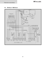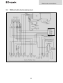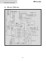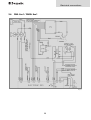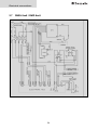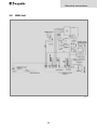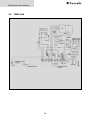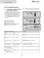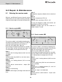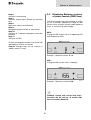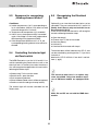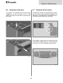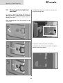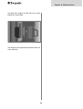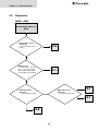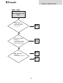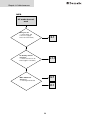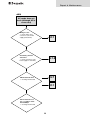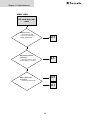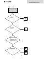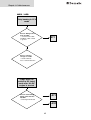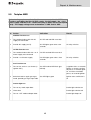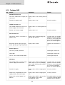
1
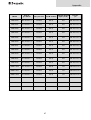
Service-Instruction
COOL
3110
Absorption Refrigerators for Leisure Vehicles
RM 8400 RM 8401 RM 8405 RM 8500 RM 8501 RM 8505 RM 8550 RM 8551 RM 8555
RMS 8400 RMS 8401 RMS 8405 RMS 8460 RMS 8461 RMS 8465 RMS 8500 RMS 8501
RMS 8505 RMS 8550 RMS 8551 RMS 8555 RML 8550 RML 8551 RML 8555 RMSL 8500
RMSL 8501 RMSL 8505 RMD 8501 RMD 8505 RMD 8551 RMD 8555
Publication No.:
599 7192-62 EN
T.B. MBA 03/2011
N 2
English
Table of contents
1.0
1.1
1.2
1.3
1.4
1.5
1.6
1.7
2.0
Description of model . . . . . . . . . . . . . . . . . . . . . . . . . . . . . . . . . . . .
4
Model identification . . . . . . . . . . . . . . . . . . . . . . . . . . . . . . . . . . . . . . . . . . . . . . . . . . . . . . . . . .
Technical data . . . . . . . . . . . . . . . . . . . . . . . . . . . . . . . . . . . . . . . . . . . . . . . . . . . . . . . . . . . . . .
Technical data . . . . . . . . . . . . . . . . . . . . . . . . . . . . . . . . . . . . . . . . . . . . . . . . . . . . . . . . . . . . . .
Description of refrigerator . . . . . . . . . . . . . . . . . . . . . . . . . . . . . . . . . . . . . . . . . . . . . . . . . . . . .
Terminal block . . . . . . . . . . . . . . . . . . . . . . . . . . . . . . . . . . . . . . . . . . . . . . . . . . . . . . . . . . . . . .
General . . . . . . . . . . . . . . . . . . . . . . . . . . . . . . . . . . . . . . . . . . . . . . . . . . . . . . . . . . . . . . . . . . . .
Explanation of operating controls . . . . . . . . . . . . . . . . . . . . . . . . . . . . . . . . . . . . . . . . . . . . . . .
4
4
5
6
9
10
11
Components . . . . . . . . . . . . . . . . . . . . . . . . . . . . . . . . . . . . . . . . . . 12
2.1
Power modules . . . . . . . . . . . . . . . . . . . . . . . . . . . . . . . . . . . . . . . . . . . . . . . . . . . . . . . . . . . . .
12
2.1.1
2.1.2
2.1.3
2.1.4
2.1.5
Power module RM 8xxx1 (MES) . . . . . . . . . . . . . . . . . . . . . . . . . . . . . . . . . . . . . . . . . . . . . . . . . . . . . . . . .
Power module RM 8xxx5 (AES) . . . . . . . . . . . . . . . . . . . . . . . . . . . . . . . . . . . . . . . . . . . . . . . . . . . . . . . . .
Power module RMD 8xxx1 (MES) . . . . . . . . . . . . . . . . . . . . . . . . . . . . . . . . . . . . . . . . . . . . . . . . . . . . . . .
Power module RMD 8xxx5 (AES) . . . . . . . . . . . . . . . . . . . . . . . . . . . . . . . . . . . . . . . . . . . . . . . . . . . . . . . .
Operating principle . . . . . . . . . . . . . . . . . . . . . . . . . . . . . . . . . . . . . . . . . . . . . . . . . . . . . . . . . . . . . . . . . .
12
12
13
13
14
2.2
2.3
2.4
2.5
2.6
Temperature sensor NTC . . . . . . . . . . . . . . . . . . . . . . . . . . . . . . . . . . . . . . . . . . . . . . . . . . . . . .
Burner Control Device t P810 . . . . . . . . . . . . . . . . . . . . . . . . . . . . . . . . . . . . . . . . . . . . . . . . . .
Gas valve GV100 . . . . . . . . . . . . . . . . . . . . . . . . . . . . . . . . . . . . . . . . . . . . . . . . . . . . . . . . . . . .
Gas burner . . . . . . . . . . . . . . . . . . . . . . . . . . . . . . . . . . . . . . . . . . . . . . . . . . . . . . . . . . . . . . . . .
Interior light and Door Lock . . . . . . . . . . . . . . . . . . . . . . . . . . . . . . . . . . . . . . . . . . . . . . . . . . . .
14
14
15
15
16
3.0
3.1
3.2
3.3
3.4
3.5
3.6
3.7
3.8
3.9
4.0
Wiring diagrams . . . . . . . . . . . . . . . . . . . . . . . . . . . . . . . . . . . . . . . . 18
RM 8xx0 / RMS 8xx0 . . . . . . . . . . . . . . . . . . . . . . . . . . . . . . . . . . . . . . . . . . . . . . . . . . . . . . . . .
RM 8xx1 / RMS 8xx1 . . . . . . . . . . . . . . . . . . . . . . . . . . . . . . . . . . . . . . . . . . . . . . . . . . . . . . . . .
RM 8xx5 / RMS 8xx5 . . . . . . . . . . . . . . . . . . . . . . . . . . . . . . . . . . . . . . . . . . . . . . . . . . . . . . . . .
RM 8xx5 with electrical door lock . . . . . . . . . . . . . . . . . . . . . . . . . . . . . . . . . . . . . . . . . . . . . . .
RML 8xx0 / RMSL 8xx0 . . . . . . . . . . . . . . . . . . . . . . . . . . . . . . . . . . . . . . . . . . . . . . . . . . . . . . .
RML 8xx1 / RMSL 8xx1 . . . . . . . . . . . . . . . . . . . . . . . . . . . . . . . . . . . . . . . . . . . . . . . . . . . . . . .
RML 8xx5 / RMSL 8xx5 . . . . . . . . . . . . . . . . . . . . . . . . . . . . . . . . . . . . . . . . . . . . . . . . . . . . . . .
RMD 8xx1 . . . . . . . . . . . . . . . . . . . . . . . . . . . . . . . . . . . . . . . . . . . . . . . . . . . . . . . . . . . . . . . . .
RMD 8xx5 . . . . . . . . . . . . . . . . . . . . . . . . . . . . . . . . . . . . . . . . . . . . . . . . . . . . . . . . . . . . . . . . .
18
19
20
21
22
23
24
25
26
Troubleshooting . . . . . . . . . . . . . . . . . . . . . . . . . . . . . . . . . . . . . . . . 28
4.1
Information on failure display and trouble-shooting . . . . . . . . . . . . . . . . . . . . . . . . . . . . . . . . .
28
4.1.1
Status messages on the display . . . . . . . . . . . . . . . . . . . . . . . . . . . . . . . . . . . . . . . . . . . . . . . . . . . . . . . .
28
5.0
Repair & Maintenance . . . . . . . . . . . . . . . . . . . . . . . . . . . . . . . . . . . 30
5.1
Entering the service mode . . . . . . . . . . . . . . . . . . . . . . . . . . . . . . . . . . . . . . . . . . . . . . . . . . . . .
30
3.1.1
3.1.2
Entering service mode MES . . . . . . . . . . . . . . . . . . . . . . . . . . . . . . . . . . . . . . . . . . . . . . . . . . . . . . . . . . . .
Entering service mode AES . . . . . . . . . . . . . . . . . . . . . . . . . . . . . . . . . . . . . . . . . . . . . . . . . . . . . . . . . . . .
30
30
5.2
5.3
5.4
5.5
5.6
5.7
5.8
5.9
5.10
Displaying Software versions of power module (RMD 8xxx) . . . . . . . . . . . . . . . . . . . . . . . . . . .
Sequence for recognizing "Heating element defect" . . . . . . . . . . . . . . . . . . . . . . . . . . . . . . . .
Controlling the interior light via door switch . . . . . . . . . . . . . . . . . . . . . . . . . . . . . . . . . . . . . . .
Recognising the electrical door lock . . . . . . . . . . . . . . . . . . . . . . . . . . . . . . . . . . . . . . . . . . . . .
Removal of the door . . . . . . . . . . . . . . . . . . . . . . . . . . . . . . . . . . . . . . . . . . . . . . . . . . . . . . . . .
Removal of the fascia . . . . . . . . . . . . . . . . . . . . . . . . . . . . . . . . . . . . . . . . . . . . . . . . . . . . . . . .
Removal of the interior light and door lock . . . . . . . . . . . . . . . . . . . . . . . . . . . . . . . . . . . . . . . .
Flowcharts . . . . . . . . . . . . . . . . . . . . . . . . . . . . . . . . . . . . . . . . . . . . . . . . . . . . . . . . . . . . . . . . .
Testplan MES . . . . . . . . . . . . . . . . . . . . . . . . . . . . . . . . . . . . . . . . . . . . . . . . . . . . . . . . . . . . . . .
31
32
32
32
33
33
34
36
43
2
5.11
Testplan AES . . . . . . . . . . . . . . . . . . . . . . . . . . . . . . . . . . . . . . . . . . . . . . . . . . . . . . . . . . . . . . .
6.0
Appendix . . . . . . . . . . . . . . . . . . . . . . . . . . . . . . . . . . . . . . . . . . . . . 46
6.1
6.2
List of gas burners and jets . . . . . . . . . . . . . . . . . . . . . . . . . . . . . . . . . . . . . . . . . . . . . . . . . . . .
Overview software changes . . . . . . . . . . . . . . . . . . . . . . . . . . . . . . . . . . . . . . . . . . . . . . . . . . . .
Dometic GmbH
In der Steinwiese 16
D-57074 Siegen
www.dometic.com
© Dometic GmbH - 2007-2011 - Subject to change without prior notice
3
44
46
48
Description of model
1.0 Description of model
1.1
1.2
Model identification
Refrigerator rating plate
The rating plate is to be found on the inside of
the refrigerator. It contains all important details
of the refrigerator. You can read off from this
the model identification, the product number
and the serial number. You will need these
details whenever you contact the customer
service centre or when ordering spare parts.
Example :
RM (S) (L) 8 4 0 0
1
(D)
5
Depth:
0 = Standard
5 = + 55mm
6 = + 65mm
1
2
3
4 = Width 486mm
5 = Width 525mm
Model range
4
„Large“
5
S= Stepped cabinet
D = double door fridge
Refrigerator Mobile /
Mobile Absorption Refrigerator
Fig. 1
0 = manual energy selection + manual ignition (battery igniter)
1
Model number
2
Product number
3
Serial number
4
Electrical rating details
5
Gas pressure
1 = manual energy selection, automatic ignition (MES)
Dometic refrigerators are equipped for a connection pressure of 30 mbar. For connection
to a 50 mbar gas system, use Truma VDR
50/30 medium pressure controller.
5 = automatic and manual energy selection,
automatic ignition (AES)
4
Description of model
1.3
Technical data
RMS 8xxx
RM 8xxx
RML 8xxx
RMD 8xxx
H
T
B
Fig. 2
Model
Fig. 3
Dimensions
Gross capacity
H x W x D (mm) with
without
Depth incl. door
freezer compartment
Fig. 5
Fig. 4
Rating details
mains/battery
Consumption *
electricity/gas
over 24hrs
Net
weight
Ignition
Piezo Automat
RMS 8400
821x486x568
80 / 8 lit.
85 lit.
125 W / 120 W
ca.2,5 KWh / 270 g
25 kg
RMS 8401
821x486x568
80 / 8 lit.
85 lit.
125 W / 120 W
ca.2,5 KWh / 270 g
25 kg
RMS 8405
821x486x568
80 / 8 lit.
85 lit.
125 W / 120 W
ca.2,5 KWh / 270 g
25 kg
RM 8400
821x486x568
90 / 8 lit.
95 lit.
135 W / 130 W
ca.2,4 KWh / 270 g
27 kg
RM 8401
821x486x568
90 / 8 lit.
95 lit.
135 W / 130 W
ca.2,4 KWh / 270 g
27 kg
RM 8405
821x486x568
90 / 8 lit.
95 lit.
135 W / 130 W
ca.2,4 KWh / 270 g
27 kg
RMS 8460
821x486x633
90 / 11 lit.
96 lit.
125 W / 120 W
ca.2,5 KWh / 270 g
26 kg
RMS 8461
821x486x633
90 / 11 lit.
96 lit.
125 W / 120 W
ca.2,5 KWh / 270 g
26 kg
RMS 8465
821x486x633
90 / 11 lit.
96 lit.
125 W / 120 W
ca.2,5 KWh / 270 g
26 kg
RMS 8500
821x523x568
90 / 9 lit.
96 lit.
125 W / 120 W
ca.2,5 KWh / 270 g
26 kg
RMS 8501
821x523x568
90 / 9 lit.
96 lit.
125 W / 120 W
ca.2,5 KWh / 270 g
26 kg
RMS 8505
821x523x568
90 / 9 lit.
96 lit.
125 W / 120 W
ca.2,5 KWh / 270 g
26 kg
RMS 8550
821x523x623
103 /12 lit.
110 lit.
125 W / 120 W
ca.2,6 KWh / 270 g
27 kg
RMS 8551
821x523x623
103 /12 lit.
110 lit.
125 W / 120 W
ca.2,6 KWh / 270 g
27 kg
RMS 8555
821x523x623
103 /12 lit.
110 lit.
125 W / 120 W
ca.2,6 KWh / 270 g
27 kg
RM 8500
821x523x568
100 / 9 lit.
106 lit.
135 W / 130 W
ca.2,4 KWh / 270 g
28 kg
RM 8501
821x523x568
100 / 9 lit.
106 lit.
135 W / 130 W
ca.2,4 KWh / 270 g
28 kg
RM 8505
821x523x568
100 / 9 lit.
106 lit.
135 W / 130 W
ca.2,4 KWh / 270 g
28 kg
RM 8550
821x523x623
115 /12 lit.
122 lit.
135 W / 130 W
ca.2,6 KWh / 270 g
30 kg
RM 8551
821x523x623
115 /12 lit.
122 lit.
135 W / 130 W
ca.2,6 KWh / 270 g
30 kg
RM 8555
821x523x623
115 /12 lit.
122 lit.
135 W / 130 W
ca.2,6 KWh / 270 g
30 kg
RML 8550
1245x525x625
179 /33 lit.
189 lit.
190 W / 170 W
ca.3,2 KWh / 380 g
45 kg
RML 8551
1245x525x625
179 /33 lit.
189 lit.
190 W / 170 W
ca.3,2 KWh / 380 g
45 kg
•
RML 8555
1245x525x625
179 /33 lit.
189 lit.
190 W / 170 W
ca.3,2 KWh / 380 g
45 kg
•
RMSL 8500
1245x525x568
145 /28 lit.
155 lit.
190 W / 170 W
ca.3,2 KWh / 380 g
40 kg
RMSL 8501
1245x525x568
145 /28 lit.
155 lit.
190 W / 170 W
ca.3,2 KWh / 380 g
40 kg
•
RMSL 8505
1245x525x568
145 /28 lit.
155 lit.
190 W / 170 W
ca.3,2 KWh / 380 g
40 kg
•
RMD 8501
1245x525x567
160 /30 lit.
-----
190 W / 170 W
ca.3,2 KWh / 380 g
40 kg
•
RMD 8505
1245x525x567
160 /30 lit.
-----
190 W / 170 W
ca.3,2 KWh / 380 g
40 kg
•
RMD 8551
1245x525x622
190 /35 lit.
-----
190 W / 170 W
ca.3,2 KWh / 380 g
41.5 kg
•
RMD 8555
1245x525x622
190 /35 lit.
-----
190 W / 170 W
ca.3,2 KWh / 380 g
41.5 kg
•
RMS = stepped cabinet
Subject to technical changes.
*Average consumption measured at an average ambient
temperature of 25°C in pursuance of ISO Standard
5
•
•
•
•
•
•
•
•
•
•
•
•
•
•
•
•
•
•
•
•
•
•
•
Description of model
1.4
Description of refrigerator
1
2
4
8
3
5
6
9
7
Fig. 6
1
Operating controls
2
Door locking button
3
Freezer compartment (removable)
4
Insertable grid shelf (available as option, to be used when freezer compartment is removed)
5
Post-evaporator for cooling compartment
6
Condensation water drain channel
7
Vegetable bin
8
Upper door shelf with flap, egg shelf available as option may be inserted
9
Lower door shelf with bottle holders
6
Description of model
Back side RM 8xxx
1
2
3
4
5
6
7
Fig. 7
1
Power module (electronics)
2
230V-connection directly to power module
3
Terminal strip for 12VDC supply
4
Burner control device
5
Gas valve
6
Main connection gas supply
7
Gas burner (behind cover)
7
Description of model
Back side RMD 8xxx
8
4
7
1
5
6
2
3
Fig. 8
1
Power module (electronics)
2
230V-connection directly to power module
3
Terminal strip for 12VDC supply
4
Burner control device
5
Gas valve
6
Main connection gas supply
7
Gas burner (behind cover)
8
Cable to operating panle (front side)
8
Description of model
1.5
Terminal block
RM 8xxx
Connections:
A = Ground heating element DC
B = Plus heating element DC
C = Ground electronics
D = Plus electronics
geräteseitig
D+ S+ –
– +
D+ = alternator signal
S+ = AES-input-control signal
(solar charge regulator)
C D
+
A B
fahrzeugseitig
Fig. 9
RMD 8xxx
on the appliance
1
2
1
B
-
A
+
on the vehicle
Fig. 11
Fig. 10
1
A = Plus heating element DC
B = Ground heating element DC
2
C = Ground electronics
D = Plus electronics
D+ = alternator signal
S+ = AES-input-control signal
(solar charge regulato
on the appliance
2
-
+
C D
D+ S+
on the vehicle
Fig. 12
9
Description of model
1.6
General
Additional features RMD 8xxx
Fridges of the 8-series with manual ignition
are provided with a battery igniter and a GasOperation-Indicator (Galvanometer ).
For using the locking button, the panel is formed asymmetric (recess on one side). I.e.
changing the door rabbet is not possible any
more. The rabbet has to be determined before the fridge is installed.
The product number controls the side of the
door rabbet. Please notify this, if the door or
the fridge is exchanged!
Failures are indicated by flashing of the red
external failure indicator LED.
Should the door be kept open for too long
(more than 2 minutes), the blue external
LED starts flashing until the door is closed.
Only with AES models RMD 8xx5 :
Should the electronic control detect any failure, an acoustic signal will sound (pulsing
whistle tone) for 30 seconds (. It is repeated
every hour, if the failure ist not resolved.
At all RM 8xxx models the door seal is
exchangeable.
Additional features MES / AES
If the door is open, the interior lighting is switched off automatically after 2 minutes.
10 seconds after the button has been pushed
for the last time, the indication (LED) switches into the dim-mode. The dim-mode is
reversed by pushing a button. The desired
function is activated by pushing the button
again.
Failures are indicated by flashing of the failure indicator LED..
Additional features AES
Should the door be kept open for too long
(more than 2 minutes), an acoustic signal is
initiated (pulsing whistle tone).
Should the electronic control detect any failure, an acoustic signal will sound (pulsing
whistle tone) for 60 seconds .
10
A description of the components of RM
8xx0 (piezo) models can be found in the
instruction 599 5175-18 EN (RM 7xxx
models).
Description of model
1.7
Explanation of operating
controls
Manual energy selection / manual ignition (RM 8xx0) battery igniter:
1
2
3
4
Fig. 13
Manual energy selection / automatic ignition (RM 8xx1) MES:
2
1
8
Mode
5
9
6
7
Fig. 14
Automatic energy selection / automatic ignition (RM 8xx5) AES:
1
2
8
Mode
5
9
6
7
Fig. 15
Manual energy selection / automatic ignition (RMD 8xx1) MES:
5
1
2
12
Mode
11
6
13
7
Indication of operating status at AES model with 7-segment display
11
2=
2
3=
3
4=
4
5=
5
6=
6
7=
7
10
Fig. 16
8 Door opening (only when equipped with
8=
electrical door lock))
9=
9 Indicator LED door lock (optional)
10 Power On switch frame heating
11 Indicator LED frame heating
12 External display Failure (red)
13 External display Apliance in operation (blue)
Power On switch / Energy selector switch
Temperature selection
PIEZO-ignition (battery igniter)
Flame indicator (galvanometer) (PIEZO-models)
Indicator LED failure
Indikator-LED / operating mode display
Temperature level display
11
Components
2.0 Components
2.1
Power modules
2.1.1 Power module RM 8xx1 ( MES)
X105
X114
X108
X110
X111
X109
X102
J4/J5
X101
J1/J2
Fuse* 1A / 250V
Connection to display
Fig. 17
X105 = 12 V Supply / - Wiring Recognition of heating element
X114 = Reed switch or alt. electr. lock
X108 = Temperature sensor (NTC)
X110 = Connection burner control device (+/-, failure)
X111 = alt. 2. electr. Lock or reed switch
X109 = Lighting
J4/J5 = Frame heating
J1 = +12 V IN for heating element
J2 = +12 V Heating element
X102 = Heating element mains power
X101 = mains power inlet
*Fuse 12V
2.1.2 Power module RM 8xx5 ( AES)
X105
X114
X108
X110
X111
X106
X102
X109
X101
X109
Fuse* 1A / 250V
J1/J2
RF Module for RMCD
remote control
Connection to display
Fig. 18
X105 = 12 V Supply / - Wiring Recognition of heating element
X114 = Reed switch or alt. electr. lock
X108 = Temperature sensor (NTC)
X110 = Connection burner control device (+/-, failure)
X111 = alt. 2. electr. Lock or reed switch
X109 = Lighting
J4/J5 = Frame heating
J1 = +12 V IN for heating element
J2 = +12 V Heating element
X102 = Heating element mains power
X101 = mains power inlet
*Fuse 12V
12
Components
2.1.3 Power module RMD 8xx1 ( MES)
X105
X115 X108
X110
X111
X109
X102
J4/J5
X101
J1/J2
Fuse* 1A / 250V
Connection to display
Fig. 19
X105 = 12 V Supply / - Wiring Recognition of heating element
X115 = 3 pin connection from display moduls to external LEDs (operating display)
X108 = Temperature sensor (NTC)
X110 = Connection to burner control device (+/-, failure)
X111 = Door switch for interior light
X109 = Interior light
J4/J5 = Frame heating
J1 = +12 V IN for heating element
J2 = +12 V Heating element
X102 = Heating element mains power
X101 = Mains power inlet
*Fuse12V
2.1.4 Power module RMD 8xx5 ( AES)
X105
X115
X108
X110
X111
X106
X109
J4/J5
X102
X101
J1/J2
Fuse* 1A / 250V
Connection to display
Fig. 20
X105 = 12 V Supply / - Wiring Recognition of heating element
X115 = 3 pin connection from display moduls to external LEDs (operating display)
X108 = Temperature sensor (NTC)
X110 = Connection to burner control device (+/-, failure)
X111 = Door switch for interior light
X106 = D+/Solar+ - connection
X109 = Interior light
J4/J5 = Frame heating
J1 = +12 V IN for heating element
J2 = +12 V Heating element
X102 = Heating element mains power
X101 = Mains power inlet
*Fuse 12V
Differences to MES/AES RM 8xxx:
X114 no electrical door lock
X115 new, connection for exteranl LED
RF function eliminated on AES board
13
Components
2.1.5 Operating principle
2.2
The electronics regulates the function of the
components according to the selected energy,
e.g. power supply for the heating elements. In
addition the AES-power module ensures the
operating with the optimal energy source according to the priority "230V AC - 12V DC - GAS".
It also controlles the low voltage operation at
230V AC (no low voltage op. at 12V DC mode),
and the "refuelling stop function" as well. The
temperature sensor and interior light are also
controlled by the electronics. The power module is protected with 1A fuse for 12 VDC.
NTC - table of resistances
No low-voltage-control during 12V mode at
RMD-models.
Temperature sensor NTC
Temperature °C
Resistance in kOhm
0
5
10
15
20
25
27.70
22.29
18.07
14.74
12.11
10.00
Measuring points:
electronics / power module
loosen contacts X108
cable white / brown
In case of a defective sensor, the fridge operates in
intervalls (45 min. ON; 14 min OFF).
Differences power module RMD 8xxx to
RM 8xxx
Controls are hidden behind the door; integrated between freezer and cooling compartment. Status is shown by blue LED (fridge
working) and red LED (error).
In Auto Mode “AES” is shown on the display
(instead of “AU”).
No electrical doorlock available.
Frame heater activation via right button.
Automatic switch off of the frame heater after
2 hours.
Acoustic alarm limited to 1 minute, but
repeated every hour (if error has not been
reseted)
Powermodul mounted on the lower back.
Access via lower ventilation grid.
2.3
Burner Control device P810
activates ignition
flame control and flame failure device
controles gas valve ( closes valve if failure oc
cure)
Power supply : ca. 1.5 V ( only measurable if no
failure exists)
Measuring points : Flat plug
between Pin 6 and Pin 7
8
7 6
1
-+
The functionality of RMD 8xxx models will
also be valid for RM 8xx1 and RM 8xx5
models probably starting with season 2010.
= 1.5 VDC
Fig. 21
14
Components
2.4
Gas valve GV 100
2.5
Gas burner
This component includes two gas valves in serial
mounting (as part of gas safety device).
voltage supply : per valve approx. 0,7V - 0,9V
(switched on gas mode)
2
inductive resistance : per valve approx. 48-50
Ohm
3
1
Measuring points: voltage and resistance
valve 1: Pin 1 – ground
valve 2: Pin 2 – ground
Fig 23
11 Ignition electrode
2=
2 Ionisation electrode
3=
3 Ground (connection to burner control device)
GND
Pin 1
Pin 2
2.5.1 Cleaning of burner
Fig 22
The burner and the chimney must be cleaned
regularly, at least one time a year.
If Autogas is used, Dometic recommends a
maintenance every half year, as the contamination risk of the burner is higher, due to the burning of the auto gas.
A listing of burners and jets can be found in
chpt. 6.1 .
15
Components
2.6
Interior light and Door Lock
Electrical door lock (option)
The Interior light and the door lock are unit,
which is exchanged completely in case of a
defect. The transparent cover is not included,
but a separate part. After removing the cover,
the lighting housing can be dismantled.
As an option an electrical door lock was available which locks the door automatically while the
engine is running. With switched off engine the
door is kept shut by a magnetic sealing, but
not locked.
Fig. 26
Fig. 24
The locking bar inside the door is fixed with two
screws, which are behind a plastic cover.
Recognising interior light and door lock
(until 2010)
Interior light and door lock are recognised by a
door switch. The door switch is mounted behind
the fascia.
Fig. 25
Fig. 27
16
Components
Recognising interior light and door lock
(starting I/2010), all models RM 8xxx and
RMD 8xxx
The door opening is recognised by a micro
switch (1)
1 in the door lock housing.
Door closed = contact open
Door open = contact closed
1
Fig. 28
Connection details LED-PCB
Sensor
LED
+
Fig. 29
17
Electrical connections
3.0 Wiring diagrams
3.1
RM 8xx0 / RMS 8xx0
Fig. 30
18
Electrical connections
3.2
RM 8xx1 / RMS 8xx1
Fig. 31
19
Electrical connections
3.3
RM 8xx5 / RMS 8xx5
Fig. 32
20
Electrical connections
3.4
RM 8xx5 with electrical door lock
Fig. 33
21
Electrical connections
3.5
RML 8xx0 / RMSL 8xx0
Fig. 34
22
Electrical connections
3.6
RML 8xx1 / RMSL 8xx1
Fig. 35
23
Electrical connections
3.7
RMSL 8xx5 / RMD 8xx5
Fig. 36
24
Electrical connections
3.8
RMD 8xx1
Fig. 37
25
Electrical connections
3.9
RMD 8xx5
Fig. 38
26
Electrical connections
27
Troubleshooting
4.0 Troubleshooting
4.1
4.1.1
Information on failure display
and trouble-shooting
Refrigerators with an electronics system
(MES, AES) indicate the occurence of a malfunction by the LED or display flashing.
Status messages on the display
1
3
2
If a malfunction occurs, the indicator LED
"Failure" (1)
1 flashes simultaneously. In the
case of AES models an acoustic alarm
sounds.
Fig. 39
11
11 = Indicator LED failure
22 = Operating mode display
33 = Temperature level display
44 = additonal Indicator LED failure RMD
55 = Operating mode display RMD
3
2
Fig. 40
RMD 8xxx
Mode
1
4
5
Fig. 41
Failure :
Display : LED (1)
1 flashes +
MES
AES
LED is flashing
"230" is flashing
230V mode: "230V" not available or voltage too
low
LED is flashing
"12" is flashing
12V mode: "12V" not available or voltage too low
LED is flashing
"GAS" is flashing
GAS/Auto mode: Flame not ignited
All temperature setting
LEDs are flashing
Temperature sensor defective, refrigerator works
on mid temperature setting
LED + all temperature setting
LEDs are flashing
"HE1" is flashing
230V - Heating element defective / or cooling unit
LED + all temperature setting
LEDs are flashing
"HE2" is flashing
12V - Heating element defective / or cooling unit
All temperature setting
LEDs are flashing
28
Troubleshooting
29
Repair & Maintenance
5.0 Repair & Maintenance
5.1
Entering the service mode
RM 8xx1 and RM 8xx5 have an internal service
mode which can be used for testing and adjusting the interior light or the electrical door lock.
Step 7:
Recognition sequence (Reed switch or electrical
lock)
Step 8:
activates temperature LEDs (4)
Step 9:
activates lock and failure LED (2) + (5)
To leave the diagnosis mode: Push button „2“
repeatedly or wait for 10 minutes.
Caution: Changes then are not saved or if
„Mode“ button is used!
5.1.1 Service mode MES
1
4
5
2
6
3
5.1.2 Service mode AES
1
2
Fig. 42
The service mode is activated by keeping pressed down the temperature button (2) on the left
side and switching on the main button (1).
After this all 3 mode-LEDs light up.
By pushing the temperature button (2), the different test-steps can be activated, test steps 1-6
are indicated by the temperature LEDs (3).
Step 1:
activates 230 V heating element (230V must be
available)
Step 2:
activates 230V relay (230V has not to be necessarily available)
Step 3:
activates 12 V heating element (12V has to be
available)
Step 4:
activates burner control device – output (Gas
operation)
Step 5:
activates frame heating
Step 6:
activates interior lights (for fridges with electrical
lock)
3
Fig. 43
The service mode is activated by keeping pressed down the temperature button (2) on the left
side and switching on the main button (1).
After this all 3 mode-LEDs light up.
By pushing the temperature button (2), the different test-steps can be activated, test steps 1-6
are indicated by the temperature LEDs (3).
Step 1:
activates 230 V heating element (230V must be
available)
Step 2:
activates 230V relay (230V has not to be necessarily available)
Step 3:
activates 12 V heating element (D+ and 12V
supply has to be available
Step 4:
Intern test step (is not indicated)
Step 5:
activates burner control device – output (Gas
operation)
30
Repair & Maintenance
5.2
Step 6:
activates frame heating
Step 7:
activates interior lights (Except for electrical
lock)
Step 8:
Intern test step (is not indicated)
Step 9:
Recognizing electrical lock or reed switch
Step 10:
activates all 7 segment-components one after
the other
Step 11:
activates all LED´s
Displaying Software versions
of power module (RMD 8xxx)
The service mode starts with showing all “LEDs
on” for 3 seconds, followed by stating the SW
version status and then service mode sequence
starts as on normal 8 series fridges.
MES :
stating the SW version status via operating LED
and temperature LEDs.
To leave the diagnosis mode: Push button „2“
repeatedly or wait for 10 minutes.
Caution: Changes then are not saved or if
„Mode“ button is used!
Fig. 44
Example : Software version V 1.2
AES :
stating the SW version status via display
Fig. 45
Example : Software version V 1.66
Probably starting with season 2010 these
functions will be valid for all models RM
8xx1 and models RM 8xx5.
31
Repair & Maintenance
5.3
Sequence for recognizing
„Heating element defect“
5.5
Conditions:
Interior temperature >18°C, corresponding relay is switched on (230V or 12V), door has to be
closed for longer than 5 minutes.
Temperature of reevaporater (a) is recorded.
After 2 hours, the temperature (b) is recorded
again, if the fridge is in the same mode and no
door openings have happened (RMD).
If the temperature difference a-b < 3 °K, the
corresponding heating element error will be indicated.
5.4
Controlling the interior light
via Reed switch
The MES-Electronics uses the X114 and X111 as
well for controlling the Reed switch as well as the
electrical lock. In the Service mode, the electronics will recognize the application of a reed switch,
following the below steps.
Choose step 7 in the service mode
Deactivate D+; open the door
Push temperature button
Close the door (Reed switch will be recognized)
Continue service mode (push temp. button)
Recognising the Electrical
door lock
Optionally, max. two electrical door locks can be
controlled. They are connected to X111 and X114
(Notify, that if there is only one lock this has to
be connected to X111)
In the service mode the electronics will recognize
the locks following the below steps.
Open the door(s)
Choose step 7 in the service mode
Close the door(s)
Activate D+
Continue Service mode with step 6
The locked door will be indicated via LED 5, and
can be unlocked by pushing button 7. If you have
2 electrical
door locks, LED 5 will flash, if one lock is not lokked. (s. pg 9)
The electrical door lock is no option anymore since 2009. Only a few number of pieces of RM 8xxx models are equipped with
it.
The interior light will now be controlled via the
Reed switch.
Items 5.4 and 5.5 are not valid for RMD 8xxx
models.
32
Repair & Maintenance
5.6
Removal of the door
5.7
Removal of the fascia
This hinges are screwed onto the housing and
snapped in as well. Unscrew at first , then
unlock the hinge and the door by pushing the
lock notch.
The operation panel can be loosened by removing two screws, when the door is opened. The
electronics at the RM(D) 8xx1 and RM(D) 8xx5 is
screwed into the panel from the inside.
Fig. 46
Fig. 48
If the fridge is demounted, the operation panel
including the holding device can be loosened
very easily. It is only attached to the housing.
Fig. 47
Fig. 49
33
Repair & Maintenance
5.8
Removing interior light and
door lock
Find behind the plastic cover two screws holding the locking hook.
In case of a defective lighting the whole unit
(doorlock device) is to be changed. The transparent cover is a separate part which does not
belong to the unit.
After removing the cover the housing can be
unscrewed.
Fig. 53
Fig. 50
Electrical doorlock (was an option)
Proceed in the same way as above to remove
electrical door lock device.
Fig. 51
Fig. 54
Fig. 52
34
Repair & Maintenance
The door lock tongue is fixed with two screws
behind the cover plate.
Fig. 55
The tongue can be adjusted if the door does not
close correctly.
35
Repair & Maintenance
5.8
Flowcharts
MES / AES
Interior light does not
work
Interior light not programmed?
-> programm via servicemode
5.5
Wiring not ok?
-> check wiring (connector
X111 or 114=door switch
input; X109= light output);
note polarity for LED light!
2.1
MES / AES board
defective?
-> exchange main board
LED light module
defective?
-> exchange light module
5.7
5.1
5.8
36
Repair & Maintenance
MES / AES
Gas mode does not
work
Wiring not ok?
-> check wiring from
main board to burner
control (X110)
2.3
Burner control P810
defective?
-> check burner control
with other AES or MES
board; exchange P810
2.4
5.7
MES / AES board
defective?
-> exchange main board
2.1
37
Repair & Maintenance
MES
AC mode does not
work
Wiring not ok?
-> check wiring and
connectors (supply
X101; AC heater X102)
2.1
AC Heating element
defective?
-> check resistance of AC
heater (approx. 350 Ohm)
5.1.1
5.7
MES / AES board
defective?
-> exchange main board
2.1
38
Repair & Maintenance
AES
AC mode does not
work (although AC is
connected)
Wiring not ok?
-> check wiring and
connectors ( DC heater
supply (X103/X104)
2.1
AC Heating element
defective?
-> check resistance of AC
heater (approx. 350 Ohm)
5.1.2
5.7
AES board defective?
-> exchange main board
2.1
AC low detection not
ok? ( on Fridges older
than 8/2008)?
-> exchange main board
39
Repair & Maintenance
MES/ AES
DC mode does not
work
Wiring not ok?
-> check wiring and
connectors ( DC heater
supply (X103/X104)
2.1
DC Heating element
defective?
-> check resistance of DC
heater (approx. 1-2 Ohm)
5.1.
5.7
MES / AES board
defective?
-> exchange main board
2.1
40
Repair & Maintenance
MES / AES
Display is black;
impossible to switch
on
Wiring not ok?
->check wiring to X105
(DC supply)
2.1
Fuse broken?
->check fuse
2.1
Microprocessor hung
up?
->Make a hardware reset
by interrupting 12 VDC
(use main DC switch in
vehicle)
Fridge older than
Oct.2007?
->exchange main board
6.2.1
6.2.2
41
Repair & Maintenance
MES / AES
Relay buzzing in 12 V
mode
Reason: Wiring before
Sept. 28, 2007
-> connect white cable
and black cable of X105
to ground
2.1
Reason: vehicle’s
voltage not stable
->check terminals,
fuse of vehicle defective
Fridge does not
switch to DC (auto)
mode after the RV
engine is started
Reason: Softwarebug;
Fridge older than Dec.
20, 2007
->exchange main board
6.2.1
6.2.2
42
Repair & Maintenance
5.9
Testplan MES
Before testing make sure, that all cables are connected to the PCB !
Provide a possibility, that the 12 VDC supply , the AC supply , the +12 V
heater supply and the D+/S+ connection (only on AES) can be interrupted
easily ! The supply voltage must be between 11 VDC and 14 VDC.
No. Action
Indication
Result
1.
230 VAC Function test
1.1
Turn rotation knob to AC with AC
supply not connected
AC LED and red LED must flash
1.2
Provide AC supply (230 V)
AC LED lights green after a few
seconds
2.
12 VDC Function test
2.1
Turn rotation knob to DC with +12 V
heater supply not connected
DC LED and red LED must flash
2.2
Provide +12 V heater supply
DC LED lights green after a view
seconds
DC relay switches
3.
Gas Function test
3.1
Turn to Gas, wait ca. 5,5 minutes (3
ignition trials)
Gas LED and red LED flash (gas
lockout)
(3 ignition trials: 30 seconds
ignition, 2 minutes ventilation pause, 30 seconds ignition, 2 minutes ventilation
pause, 30 seconds ignition.
3.2
Switch off and on again; go to gas
mode, provide gas to gas input tube
Gas LED lights green
Ignition starts until flame is
on
4.
Interior light test
4.1
Turn to any mode, open door
Interior light switches on
4.2
Close door
Interior light switches off
4.3
Turn to - OFF mode and open door
Interior light keeps off
43
AC relay switches
Repair & Maintenance
5.10 Testplan AES
No. Action
Indication
Result
230 VAC Function test
Turn to AC mode with AC supply not
connected
Display shows "230" flashing with red
LED
Provide AC supply (230 V)
Display shows "230"
AC relay switches
12 VDC Function test
Turn rotation knob to DC with +12 V
heater supply not connected
Display shows "12" flashing with red
LED
Provide +12 V heater supply
Display shows "12"
DC relay switches
Display shows "GAS" flashing with
red LED (gas lockout)
3 ignition trials: 30 seconds
ignition, 2 minutes ventilation pause, 30 seconds ignition, 2 minutes ventilation
pause, 30 seconds ignition.
Gas Function test
Turn to Gas, wait ca. 5,5 minutes (3
ignition trials)
Switch off and on again; go to gas
Display shows "GAS"
mode, provide gas to gas input tube.
Ignition starts until flame is
on
Interior light test
Turn to any mode, open door
Interior light switches on
Close door
Interior light switches off
Turn to - OFF mode and open door
Interior light keeps off
AES Mode
Turn to AES mode; +12 VDC heater
and AC supply not connected
Display shows "AES" changing with
"GAS"; after ca. 5,5 min the display
shows "AES" flashing with red LED
(gas lockout).
3 ignition trials: 30 seconds
ignition, 2 minutes ventilation pause, 30 seconds ignition, 2 minutes ventilation
pause, 30 seconds ignition.
Provide AC supply
Display shows "AES" changing with
"230"
AC relay switches
Remove AC and provide DC heater
supply and D+ (alternator input)
Display shows "AES" changing with
"12"
DC relay switches
Remove DC and wait approx. 15
Minutes
Display shows "AES" ; after 15 minu- DC mode switches off; after
15 minutes (tankstop delay)
tes the display shows "AES"
ignition starts (3 attemps)
changing with "GAS"
44
Repair & Maintenance
45
Appendix
6.0 Appendix
6.1
List of gas burners and jets
Model
Part no.
gas burner
Gas pressure
Jet ID number
Nominal thermal
input ( in W)
Part no.
jet
RM 8400
292 3430-51 / 2
30 mbar
KZ 43
252
292 2033-06 / 9
RM 8401
241 2802-81 / 7
30 mbar
KZ 43
252
292 2033-06 / 9
RM 8405
241 2802-81 / 7
30 mbar
KZ 43
252
292 2033-06 / 9
RM 8500
292 3430-51 / 2
30 mbar
KZ 43
252
292 2033-06 / 9
RM 8501
241 2802-81 / 7
30 mbar
KZ 43
252
292 2033-06 / 9
RM 8505
241 2802-81 / 7
30 mbar
KZ 43
252
292 2033-06 / 9
RM 8550
292 3430-51 / 2
30 mbar
KZ 43
252
292 2033-06 / 9
RM 8551
241 2802-81 / 7
30 mbar
KZ 43
252
292 2033-06 / 9
RM 8555
241 2802-81 / 7
30 mbar
KZ 43
252
292 2033-06 / 9
RMD 8501
241 2802-81 / 7
30 mbar
KZ 16
310
292 2033-10 /1
RMD 8505
241 2802-81 / 7
30 mbar
KZ 16
310
292 2033-10 /1
RMD 8551
241 2802-81 / 7
30 mbar
KZ 16
310
292 2033-10 /1
RMD 8555
241 2802-81 / 7
30 mbar
KZ 16
310
292 2033-10 /1
RML 8550
292 3430-51 / 2
30 mbar
KZ 16
310
292 2033-10 /1
RML 8551
241 2802-81 / 7
30 mbar
KZ 16
310
292 2033-10 /1
RML 8555
241 2802-81 / 7
30 mbar
KZ 16
310
292 2033-10 /1
46
Appendix
Model
Part no.
gas burner
Gas pressure
Jet ID number
Nominal thermal
input ( in W )
Part no.
jet
RMS 8400
292 3430-51 / 2
30 mbar
KZ 43
252
292 2033-06 / 9
RMS 8401
241 2802-81 / 7
30 mbar
KZ 43
252
292 2033-06 / 9
RMS 8460
292 3430-51 / 2
30 mbar
KZ 43
252
292 2033-06 / 9
RMS 8461
241 2802-81 / 7
30 mbar
KZ 43
252
292 2033-06 / 9
RMS 8465
241 2802-81 / 7
30 mbar
KZ 43
252
292 2033-06 / 9
RMS 8500
292 3430-51 / 2
30 mbar
KZ 43
252
292 2033-06 / 9
RMS 8501
241 2802-81 / 7
30 mbar
KZ 43
252
292 2033-06 / 9
RMS 8505
241 2802-81 / 7
30 mbar
KZ 43
252
292 2033-06 / 9
RMS 8550
292 3430-51 / 2
30 mbar
KZ 43
252
292 2033-06 / 9
RMS 8551
241 2802-81 / 7
30 mbar
KZ 43
252
292 2033-06 / 9
RMS 8555
241 2802-81 / 7
30 mbar
KZ 43
252
292 2033-06 / 9
RMSL 8500
292 3430-51 / 2
30 mbar
KZ 16
310
292 2033-10 /1
RMSL 8501
241 2802-81 / 7
30 mbar
KZ 16
310
292 2033-10 /1
RMSL 8505
241 2802-81 / 7
30 mbar
KZ 16
310
292 2033-10 /1
47
Appendix
6.2
Overview software changes
6.2.1 MES models (RM 8xx1)
No. Change
Software name
Marking
introduced since
1.
MES_Jun_27
Software: DC low voltage detection
sequence changed (changes within 1
sec, if 12 V heater DC is available)
green "geprüft"sticker on housing
week 26 / 2007
2.
MES_10_Sept
Software: DC low voltage detection
reduced to 8.5 V. Sensitivity for
ground difference increased to 1.3 V ;
white ground cable linked with black
ground cable (both of X105).
white cross on
housing
week 37, 2007
3.
Software: adjusted to longer ignition
times of burner control P810
MES_Sept_28
white circle on
housing
week 41, 2007
4.
Softwareänderung; EMC improvement for frequency1 Hz-1 Mhz
MES_Oct_15
white circle with
cross on housing or sticker
on PCB
week 45, 2007
5.
MES_1.2
Version for RMD 8XX1 models
driver for external status LED
frameheater driver via right button
automatic frame heater switch off
after 2 hours no electrical doorlock
driver no "learning" necessary
when starting the servicemode all
LEDs are lighted followed by the SW
status if the door is open longer than
2 minutes, the blue external LED will
flash no DC low voltage detection.
sticker on PCB
and shown in
servicemode
week 21, 2009
48
Appendix
6.2.2 AES models (RM 8xx5)
No. Change
Software name
Marking
1.
AES_main_V1_40. white circle on
Software: DC low voltage detection
sequence changed (changes within 1 s19 (27 July 2007) housing or stikker on PCB
sec, if 12 V heater DC is available)
2.
AC low voltage detection revised
(Threshold 195 V)
3.
V1.66.s19
Version for RMD 8XX5 models
driver for external status LED
frameheater driver via right button
automatic frame heater switch off
after 2 hours no electrical doorlock
driver no "learning" necessary
when starting the servicemode all
LEDS are lighted followed by the SW
status. If the door is open longer than
2 minutes, the blue external LED will
flash no DC low voltage detection
acoustic alarm limited to 60 sec. followed every hour, if error is not confirmed
AES_main_V1_52. sticker on PCB
s19
49
sticker on PCB
and shown in
servicemode
introduced since
since December 12, 2007
since August 15, 2008
week 21, 2009
www.dometic.com