1
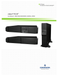
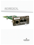
Liebert® APS™ MBC
User Manual – Rack-Mount Maintenance Bypass Cabinet
CONTACTING EMERSON NETWORK POWER FOR SUPPORT
To contact Emerson Network Power Liebert Services for information or repair service in the United
States, call 800-543-2378. Liebert Services offers a complete range of star-up services, repair services,
preventive maintenance plans and service contracts.
For repair or maintenance service outside the 48 contiguous United States, contact Liebert Services,
if available in your area. For areas not covered by Liebert Services, the authorized distributor is
responsible for providing qualified, factory-authorized service.
For Liebert Services to assist you promptly, please have the following information available:
Part numbers: _________________________________________________________________
Serial numbers:________________________________________________________________
Rating: _______________________________________________________________________
Date purchased: _______________________________________________________________
Date installed:_________________________________________________________________
Location: ______________________________________________________________________
Input voltage/frequency: ________________________________________________________
Output voltage/frequency: ______________________________________________________
DC source reserve time: ________________________________________________________
Product Warranty Registration
To register for warranty protection, visit the Service and Support section of our Web site at:
www.liebert.com
Click on Product Registration and fill out the form.
TABLE OF CONTENTS
CONTACTING EMERSON NETWORK POWER FOR SUPPORT . . . . . . . . . . . . . . . INSIDE FRONT COVER
IMPORTANT SAFETY PRECAUTIONS . . . . . . . . . . . . . . . . . . . . . . . . . . . . . . . . . . . . . . . . . . . . . . . .1
SAVE THESE INSTRUCTIONS . . . . . . . . . . . . . . . . . . . . . . . . . . . . . . . . . . . . . . . . . . . . . . . . .1
GLOSSARY OF SYMBOLS . . . . . . . . . . . . . . . . . . . . . . . . . . . . . . . . . . . . . . . . . . . . . . . . . . . . . . .3
1.0
GENERAL DESCRIPTION . . . . . . . . . . . . . . . . . . . . . . . . . . . . . . . . . . . . . . . . . . . . . . . . . . .4
1.1
System Description. . . . . . . . . . . . . . . . . . . . . . . . . . . . . . . . . . . . . . . . . . . . . . . . . . . . . . . . . . . 4
1.2
Appearance and Components . . . . . . . . . . . . . . . . . . . . . . . . . . . . . . . . . . . . . . . . . . . . . . . . . . 4
1.2.1
Bypass Indicator LED . . . . . . . . . . . . . . . . . . . . . . . . . . . . . . . . . . . . . . . . . . . . . . . . . . . . . . . . . 5
1.2.2
UPS Indicator LED. . . . . . . . . . . . . . . . . . . . . . . . . . . . . . . . . . . . . . . . . . . . . . . . . . . . . . . . . . . . 5
1.2.3
Output Indicator LED . . . . . . . . . . . . . . . . . . . . . . . . . . . . . . . . . . . . . . . . . . . . . . . . . . . . . . . . . 5
1.3
Features . . . . . . . . . . . . . . . . . . . . . . . . . . . . . . . . . . . . . . . . . . . . . . . . . . . . . . . . . . . . . . . . . . . 5
1.4
Operating Mode . . . . . . . . . . . . . . . . . . . . . . . . . . . . . . . . . . . . . . . . . . . . . . . . . . . . . . . . . . . . . 6
1.4.1
UPS Mode . . . . . . . . . . . . . . . . . . . . . . . . . . . . . . . . . . . . . . . . . . . . . . . . . . . . . . . . . . . . . . . . . . . 6
1.4.2
Maintenance Bypass mode. . . . . . . . . . . . . . . . . . . . . . . . . . . . . . . . . . . . . . . . . . . . . . . . . . . . . . 6
2.0
INSTALLATION . . . . . . . . . . . . . . . . . . . . . . . . . . . . . . . . . . . . . . . . . . . . . . . . . . . . . . . . . .7
2.1
Unpacking Inspection. . . . . . . . . . . . . . . . . . . . . . . . . . . . . . . . . . . . . . . . . . . . . . . . . . . . . . . . . 7
2.2
Installation Environment . . . . . . . . . . . . . . . . . . . . . . . . . . . . . . . . . . . . . . . . . . . . . . . . . . . . . 7
2.3
Installation Procedures . . . . . . . . . . . . . . . . . . . . . . . . . . . . . . . . . . . . . . . . . . . . . . . . . . . . . . . 7
2.4
Cable Selection And Connection . . . . . . . . . . . . . . . . . . . . . . . . . . . . . . . . . . . . . . . . . . . . . . . 10
2.4.1
Cable Selection . . . . . . . . . . . . . . . . . . . . . . . . . . . . . . . . . . . . . . . . . . . . . . . . . . . . . . . . . . . . . . 11
2.4.2
Cable Connection For Liebert APS UPS 200-240V input/output . . . . . . . . . . . . . . . . . . . . . . 12
2.4.3
Cable Connection for Liebert APS UPS 200-240V Input / 200/100-240/120V output
with integral output transformer . . . . . . . . . . . . . . . . . . . . . . . . . . . . . . . . . . . . . . . . . . . . . . . 13
2.4.4
Cable Connection for Liebert APS UPS 200/100-240/120V Input/Output . . . . . . . . . . . . . . . 15
3.0
OPERATION . . . . . . . . . . . . . . . . . . . . . . . . . . . . . . . . . . . . . . . . . . . . . . . . . . . . . . . . . . .16
3.1
Startup . . . . . . . . . . . . . . . . . . . . . . . . . . . . . . . . . . . . . . . . . . . . . . . . . . . . . . . . . . . . . . . . . . . 16
3.2
Shutdown (with Loss of All Power) . . . . . . . . . . . . . . . . . . . . . . . . . . . . . . . . . . . . . . . . . . . . . 16
3.3
Transfer of the System from UPS to Maintenance Bypass . . . . . . . . . . . . . . . . . . . . . . . . . . 16
3.4
Transfer of the System from Maintenance Bypass to UPS . . . . . . . . . . . . . . . . . . . . . . . . . . 17
4.0
TROUBLESHOOTING . . . . . . . . . . . . . . . . . . . . . . . . . . . . . . . . . . . . . . . . . . . . . . . . . . . . . 18
5.0
SPECIFICATIONS . . . . . . . . . . . . . . . . . . . . . . . . . . . . . . . . . . . . . . . . . . . . . . . . . . . . . . . .19
6.0
POD—OPTIONAL . . . . . . . . . . . . . . . . . . . . . . . . . . . . . . . . . . . . . . . . . . . . . . . . . . . . . . . 20
6.1
Introduction . . . . . . . . . . . . . . . . . . . . . . . . . . . . . . . . . . . . . . . . . . . . . . . . . . . . . . . . . . . . . . . 20
6.2
Installing the POD . . . . . . . . . . . . . . . . . . . . . . . . . . . . . . . . . . . . . . . . . . . . . . . . . . . . . . . . . . 21
i
FIGURES
Figure 1
Figure 2
Figure 3
Figure 4
Figure 5
Figure 6
Figure 7
Figure 8
Figure 9
Figure 10
Figure 11
Figure 12
Figure 13
Figure 14
Figure 15
Figure 16
Figure 17
Figure 18
Figure 19
Figure 20
Figure 21
General Liebert APS MBC appearance . . . . . . . . . . . . . . . . . . . . . . . . . . . . . . . . . . . . . . . . . . . . . . . 4
Components on the front of the Liebert APS MBC . . . . . . . . . . . . . . . . . . . . . . . . . . . . . . . . . . . . . . 4
Parts on the rear of the Liebert APS MBC . . . . . . . . . . . . . . . . . . . . . . . . . . . . . . . . . . . . . . . . . . . . 5
Operation in UPS Mode . . . . . . . . . . . . . . . . . . . . . . . . . . . . . . . . . . . . . . . . . . . . . . . . . . . . . . . . . . . 6
Operation in Maintenance Bypass Mode. . . . . . . . . . . . . . . . . . . . . . . . . . . . . . . . . . . . . . . . . . . . . . 6
Installing the cage nuts . . . . . . . . . . . . . . . . . . . . . . . . . . . . . . . . . . . . . . . . . . . . . . . . . . . . . . . . . . . 8
Attaching the rear of the rack-mount rail kit . . . . . . . . . . . . . . . . . . . . . . . . . . . . . . . . . . . . . . . . . . 8
Securing the front of the rack-mount rails . . . . . . . . . . . . . . . . . . . . . . . . . . . . . . . . . . . . . . . . . . . . 9
Installing the Liebert APS MBC . . . . . . . . . . . . . . . . . . . . . . . . . . . . . . . . . . . . . . . . . . . . . . . . . . . . 9
Completed view of the Liebert APS MBC installation . . . . . . . . . . . . . . . . . . . . . . . . . . . . . . . . . . 10
Remove the conduit boxes. . . . . . . . . . . . . . . . . . . . . . . . . . . . . . . . . . . . . . . . . . . . . . . . . . . . . . . . . 11
Connection of Liebert APS MBC’s upper terminal block (to/from UPS unit) . . . . . . . . . . . . . . . . 12
Connection of Liebert APS MBC’s lower terminal block (from main AC source/to main
distribution panel) . . . . . . . . . . . . . . . . . . . . . . . . . . . . . . . . . . . . . . . . . . . . . . . . . . . . . . . . . . . . . . 12
Connection of Liebert APS MBC’s upper terminal block (to/from UPS unit) . . . . . . . . . . . . . . . . 12
Connection of Liebert APS MBC’s lower terminal block (from main AC source/to main
distribution panel). . . . . . . . . . . . . . . . . . . . . . . . . . . . . . . . . . . . . . . . . . . . . . . . . . . . . . . . . . . . . . . 13
Connection of Liebert APS MBC’s upper terminal block (to/from UPS unit) . . . . . . . . . . . . . . . . 13
Connection of Liebert APS MBC’s lower terminal block (from main AC source / to main
distribution panel). . . . . . . . . . . . . . . . . . . . . . . . . . . . . . . . . . . . . . . . . . . . . . . . . . . . . . . . . . . . . . . 14
Connection of the upper terminal block of the Liebert APS MBC (to/from UPS unit) . . . . . . . . . 15
Connection of the lower terminal block of the Liebert APS MBC (from main AC
source / to main distribution panel) . . . . . . . . . . . . . . . . . . . . . . . . . . . . . . . . . . . . . . . . . . . . . . . . . 15
Remove the cover . . . . . . . . . . . . . . . . . . . . . . . . . . . . . . . . . . . . . . . . . . . . . . . . . . . . . . . . . . . . . . . 21
Attach the POD . . . . . . . . . . . . . . . . . . . . . . . . . . . . . . . . . . . . . . . . . . . . . . . . . . . . . . . . . . . . . . . . . 21
TABLES
Table 1
Table 2
Table 3
Table 4
Table 5
Table 6
Table 7
Table 8
Table 9
Cables and protection grade . . . . . . . . . . . . . . . . . . . . . . . . . . . . . . . . . . . . . . . . . . . . . . . . . . . . . . .
Installation reference . . . . . . . . . . . . . . . . . . . . . . . . . . . . . . . . . . . . . . . . . . . . . . . . . . . . . . . . . . . .
Connections, upper terminal block, single-phase input, L-N-PE (50Hz) or L-L-G (60Hz) . . . . . .
Connections, lower terminal block, single-phase input, L-N-PE (50Hz) or L-L-G (60Hz) . . . . . .
Troubleshooting. . . . . . . . . . . . . . . . . . . . . . . . . . . . . . . . . . . . . . . . . . . . . . . . . . . . . . . . . . . . . . . . .
Specifications. . . . . . . . . . . . . . . . . . . . . . . . . . . . . . . . . . . . . . . . . . . . . . . . . . . . . . . . . . . . . . . . . . .
Technical specifications of the POD (PD2-101 ~ PD2-105) . . . . . . . . . . . . . . . . . . . . . . . . . . . . . .
Technical specifications of the POD (PD2-106 ~ PD2-109) . . . . . . . . . . . . . . . . . . . . . . . . . . . . . .
Technical specifications of the POD (PD2-200 ~ PD2-204) . . . . . . . . . . . . . . . . . . . . . . . . . . . . . .
ii
11
11
13
14
18
19
20
20
20
Important Safety Precautions
IMPORTANT SAFETY PRECAUTIONS
SAVE THESE INSTRUCTIONS
This manual contains important safety instructions. Read all safety, installation and operating
instructions before operating the parallel UPS system. Adhere to all warnings on the unit and in this
manual. Follow all operating and user instructions. Individuals must fully understand this
equipment to install and operate it.
The Liebert APS MBC (maintenance bypass cabinet) is designed for commercial/industrial use only.
It is not intended for use with life support or other designated critical devices. Maximum load must
not exceed that shown on the rating label of the maintenance bypass cabinet (MBC). Install and
operate the Liebert APS MBC only in a clean indoor environment, free of conductive contaminants,
moisture, flammable liquids, gases and corrosive substances. The Liebert APS MBC contains no
user-serviceable parts. Refer all faults to your local dealer, local Emerson Network Power®
representative or Emerson Network Power Liebert Services.
The Liebert APS modular UPS system with MBC is designed for use on a properly earthed
(grounded), 200-240VAC, 50 or 60Hz supply. The system must be installed only by properly trained
and qualified personnel. A qualified electrician must review and approve customer-supplied wiring,
circuit breakers and intended loads and verify correct input, output and earth connections to ensure
compliance with the technical standards and local electrical codes.
! WARNING
Risk of electrical shock and high short circuit current. Can cause injury or death.
The following precautions must be observed before replacing the battery pack:
•
•
•
•
•
Wear rubber gloves and boots
Remove rings, watches and other metal objects.
Use tools with insulated handles.
Do not lay tools or other metal objects on the batteries.
If the battery kit is damaged in any way or shows signs of leakage, contact your local
Emerson representative immediately.
• Do not dispose of batteries in a fire. The batteries may explode.
• Handle, transport and recycle batteries in accordance with local regulations.
! WARNING
Risk of electrical shock, fire and high short circuit current. Can cause injury or death.
The Liebert APS MBC has been designed and manufactured to ensure personal safety, but
improper use can result in electrical shock or fire. To ensure safety, observe the following
precautions:
• Turn Off and unplug the Liebert APS MBC before cleaning it.
• Clean the unit with a dry cloth. Do not use liquid or aerosol cleaners.
• Never block or insert any objects into the ventilation holes or other openings of the Liebert
APS MBC.
• Do not place the Liebert APS MBC power cord where it might be damaged.
ELECTROMAGNETIC COMPATIBILITY—The Liebert APS MBC complies with the limits of
Category C2, pursuant to IEC/EN/AS 62040-2, and for a Class A digital device, pursuant to Part 15 of
FCC rules. Operation is subject to the following conditions:
• The output cables must be no longer than 10m (32ft).
• This device may not cause harmful interference.
• This device must accept any interference received, including interference that may cause
undesired operation. Operating this device in a residential area is likely to cause harmful
interference that users must correct at their own expense.
1
Liebert® APS™ MBC
Important Safety Precautions
The Liebert APS MBC complies with the requirements of EMC Directive 2004/108/EC and the
published technical standards. Continued compliance requires installation in accordance with these
instructions and use of accessories approved by Emerson.
NOTICE
This is a Category C2 UPS product. In a residential environment, this product may cause
radio interference, in which case the user may be required to take additional measures.
Operate the unit in an indoor environment only in an ambient temperature range of 0-40°C
(32-104°F). Install it in a clean environment, free from moisture, flammable liquids, gases and
corrosive substances.
This Liebert APS MBC contains no user-serviceable parts except the internal battery pack. The unit’s
On/Off push buttons do not electrically isolate internal parts. Under no circumstances attempt to gain
access internally, due to the risk of electric shock or burn.
Do not continue to use the Liebert APS MBC if the front panel indications are not in accordance with
these operating instructions or the performance alters in use. Refer all faults to your Emerson
representative or Liebert Services.
Servicing of batteries must be performed or supervised by properly trained and qualified personnel
knowledgeable of batteries and the required precautions. Keep unauthorized personnel away from the
batteries. Proper disposal of batteries is required. Refer to your local laws and regulations for disposal
requirements.
Never block or insert any object into the ventilation holes or other openings.
DO NOT CONNECT equipment that could overload the UPS or demand DC current from the Liebert
APS MBC, for example: electric drills, vacuum cleaners, laser printers, hair dryers or any appliance
using half-wave rectification.
Storing magnetic media on top of the Liebert APS MBC may result in data loss or corruption.
Turn Off and isolate the Liebert APS MBC before cleaning it. Use only a soft cloth, never liquid or
aerosol cleaners.
Information for the Protection of the Environment
UPS SERVICING—This unit makes use of components dangerous for the environment (electronic
cards, electronic components). The components removed must be taken to specialized collection and
disposal centers.
NOTICE TO EUROPEAN UNION CUSTOMERS: DISPOSAL OF OLD
APPLIANCES—This product has been supplied from an environmentally
aware manufacturer that complies with the Waste Electrical and Electronic
Equipment (WEEE) Directive 2002/96/CE.
The symbol at right is placed on this product to encourage recycling wherever
possible. Recycle this product through a recycling facility at the end of its
service life. Do not dispose of this product as unsorted municipal waste.
Follow local municipal waste ordinances for proper disposal provisions to
reduce the environmental impact of waste electrical and electronic equipment
(WEEE).
For information regarding the disposing of this equipment, go to www.liebert.com or contact
Emerson’s worldwide technical support. Refer to the back page of this manual for contact information.
Liebert® APS™ MBC
2
Glossary Of Symbols
GLOSSARY OF SYMBOLS
Risk of electrical shock
!
Indicates caution followed by important instructions
AC input
AC output
i
R
Consult the manual
Recycle
Equipment grounding conductor
Bonded to ground
AC voltage
WEEE
3
Liebert® APS™ MBC
General Description
1.0
GENERAL DESCRIPTION
Read this manual thoroughly to ensure proper installation and operation of this unit.
Installation must be performed by properly trained and qualified personnel. General operations can
be conducted with no need of specialized training.
This chapter describes the Liebert APS MBC, including appearance, components, features, operating
mode and specifications.
1.1
System Description
This rack-mountable MBC is intended for use with the Liebert APS, Liebert GXT3 8-10kVA or other
UPS with equivalent specifications. Typical applications include supporting workstations, servers,
network, telecommunications or other sensitive electronic equipment.
The Liebert APS MBC was designed to provide maximum system availability to business critical
equipment by allowing transfer of connected equipment to an alternate power path allowing full
isolation of the UPS for maintenance. The UPS can then be turned Off and removed from service with
no interruption of power to connected equipment.
1.2
Appearance and Components
Figure 1
General Liebert APS MBC appearance
Plastic Bezel
Figure 2
Components on the front of the Liebert APS MBC
Bezels Removed
to Reveal Components
UPS Indicator
MBC Output Breaker
UPS Input Breaker
Bypass Indicator
Maintenance Bypass Switch
Output Indicator
The front panel of the Liebert APS MBC has three LED indicators, including Bypass indicator
(amber), UPS indicator (green) and OUTPUT indicator (amber).
Liebert® APS™ MBC
4
General Description
1.2.1
Bypass Indicator LED
The amber Bypass Indicator illuminates when the maintenance bypass source is available. When the
Bypass Indicator is illuminated, it is permissible to transfer the connected equipment to Maintenance
Bypass mode by rotating the switch (see Figure 2). When the Bypass Indicator is not illuminated, the
maintenance bypass source is not ready or available and transfers should not occur.
NOTE
When the switch is in the Maintenance Bypass position, the connected equipment is not
protected by the UPS and is susceptible to any AC mains/utility anomalies and outages.
1.2.2
UPS Indicator LED
The green UPS Indicator shows when UPS output power is available. When the UPS Indicator is
illuminated, UPS output power is available to the Liebert APS MBC and it is permissible to transfer
the rotary switch to the UPS Mode (see Figure 2). When the UPS indicator is not illuminated, the
UPS output power is not ready/available and transfers should not occur.
1.2.3
Output Indicator LED
The amber Output Indicator indicates when the Liebert APS MBC main output breaker is closed and
power is available on the main output terminal block. When the Output Indicator is not illuminated,
output power is not available.
The POD ports, POD breakers and input/output terminal blocks are on the rear of the Liebert APS
MBC, as shown in Figure 3.
Figure 3
Parts on the rear of the Liebert APS MBC
POD Ports
(with Covers)
Input/Output
Terminal Blocks
POD Breaker
1.3
Features
•
•
•
•
•
•
•
Supports 8, 10, 15 or 20kVA power, depending on model
High-speed transfer switch
Compact design
Multiple power path indicators
Easily accessible terminal blocks
Rack-mountable or tower orientation
Integral output distribution options via optional PODs
5
Liebert® APS™ MBC
General Description
1.4
Operating Mode
The Liebert APS MBC permits maintaining power to all connected equipment during maintenance of
the Liebert APS. The Liebert APS MBC operates in two modes, UPS Mode and Maintenance Bypass
Mode.
1.4.1
UPS Mode
The diagram below illustrates the Liebert APS MBC operating in UPS Mode.
Figure 4
Operation in UPS Mode
AC
Input
Connected
Load
MBC
Liebert
APS
While the Liebert APS MBC is in UPS Mode, the UPS is supplying continuous, high-quality AC
power. In this operating mode, connected equipment is protected by the UPS. The maintenance
bypass switch is rotated toward the UPS indicator (green) indicates this mode.
1.4.2
Maintenance Bypass mode
The diagram below illustrates the Liebert APS MBC operating in Maintenance Bypass Mode.
Figure 5
Operation in Maintenance Bypass Mode
AC
Input
Connected
Load
MBC
Liebert
APS
While the Liebert APS MBC is in the Maintenance Bypass mode it provides an alternate path for
power to the connected equipment. Should the UPS need to be taken out of service for limited
maintenance or repair, manual activation of the bypass will immediately transfer the equipment from
the UPS inverter to the bypass source. In this mode, the connected equipment is not protected from
utility/mains power abnormalities or outages. The maintenance bypass switch is rotated toward the
Bypass Indicator (amber) in this mode.
Liebert® APS™ MBC
6
Installation
2.0
INSTALLATION
This chapter provides the steps and procedures for installing the Liebert APS MBC, including
preparation and cable selection and connection.
2.1
Unpacking Inspection
Upon receiving the Liebert APS MBC, unpack the MBC and conduct the following checks:
• Inspect the unit for shipping damage. If any shipping damage is founded, report it to the carrier.
• Check against the delivery list to verify that the types of the accessories are complete and correct.
If there is any discrepancy, contact the carrier and your Emerson representative immediately.
2.2
Installation Environment
The Liebert APS MBC environment must be free of conductive contaminants and excessive moisture
(water and condensation), flammable vapors, chemical fumes, corrosive gases and liquids.
2.3
Installation Procedures
Installation Tools
The tools required to properly set up your UPS are listed below:
• 13mm (1/2 in) wrench or socket
• #1 and #2 Phillips screwdrivers
• Torque wrench
If the Liebert APS MBC is to be installed in a rack enclosure, see the following for the installation
procedures:
NOTE
The Liebert APS MBC is rack-mountable. If the Liebert APS is to be rack mounted and there is
no UPS in the rack, please first install the UPS before installing the Liebert APS MBC. If there
is UPS in the rack and the UPS is operating, please turn off the UPS, disconnect the local
input breaker and loads, and remove the UPS Input/ Output cables according to the
corresponding UPS user manual.
1. Locate the rack-mount rails from the Liebert APS MBC packaging and review the following
procedures to install the rails onto the vertical pole of the rack:
2. Install the cage nuts in the middle square holes of the 1U and 2U height space, the upper square
holes of the 3U and 6U height spaces and in the lower square holes of the 5U and 8U height
spaces, as shown in Figure 6.
NOTE
The height space indicates the whole U height space counted from the top of the Liebert APS
UPS. The 1U and 2U height spaces are used to install the guide rails. The 3U, 6U, 5U and 8U
height spaces are used to install the securing brackets of the Liebert APS MBC.
7
Liebert® APS™ MBC
Installation
Figure 6
Installing the cage nuts
Vertical Rail
Cage Nut, 12
3. Using the hook on the rear flange of the rack-mount rail, clip it onto the rear vertical pole and use
the provided four M6 x 16 screws to secure them, as shown in Figure 7.
Figure 7
Attaching the rear of the rack-mount rail kit
Guide Rail
Rear Vertical Rail
Hook
Installation Hole,
2 Places
M6 x 16 Screws, 4
4. Using the provided four M6 x 16 screws, secure the front of the rack-mount rails onto the vertical
pole, as shown in Figure 8.
Liebert® APS™ MBC
8
Installation
Figure 8
Securing the front of the rack-mount rails
Front Vertical Rail
M6 x 16 Screws, 4
5. Remove the Liebert APS MBC from the shipping carton and install it using the following steps:
6. Lift the Liebert APS MBC and place it on the guide rails. Slide it into the rack.
NOTE
The weight of the Liebert APS MBC is 30kg (66 lb.), please be careful when lifting it. This may
require two people.
Figure 9
Installing the Liebert APS MBC
Liebert APS MBC
Rack-Mount Rail
Liebert APS
7. Using the provided eight M6 x 16 screws, securing the Liebert APS MBC to the front vertical post.
See Figure 10 for the completed assembly view.
9
Liebert® APS™ MBC
Installation
Figure 10 Completed view of the Liebert APS MBC installation
8. Refer to 2.4 - Cable Selection And Connection for wiring connections.
9. Refer to 6.0 - POD—Optional for installing any integral output distribution PODs.
2.4
Cable Selection And Connection
Installation Tools
The tools required to properly set up your UPS are listed below:
• 13mm (1/2 in) wrench or socket
• #1 and #2 Phillips screwdrivers (cross-head)
• Torque wrench
Liebert® APS™ MBC
10
Installation
2.4.1
Cable Selection
Select proper cable size/amperage based on the Liebert APS MBC model. The models have different
circuit breaker ratings. See Table 1 for the amperages for proper cable selection.
Table 1
Cables and protection grade
Model
ASMBCR2
Series
ASMBCR1
Series
ASMBCRG
Series
ASMBCRW
Series
Maximum Input Current
125A
100A
63A
50A
Input Protection
125A
100A
63A
50A
Maximum Output Current
125A
100A
63A
50A
Item
2
Maximum: 2/0 (60mm )
Minimum: 6 AWG (22mm2)
Terminal Block
Wire Size Range
90°C rated copper wire is recommended
Terminal block torque requirements are 4.52Nm (40 in-lb)
The Liebert APS unit model number determine which section to follow for the installation
instructions for the Liebert APS MBC.
Table 2
Installation reference
UPS Model Number
Digits 1-3
UPS System Voltage and Frame Type
See
Manual Section
AS1 or ASA
200-240V Input / Output; Transformer-Free
2.4.2
AS2 or ASB
200-240V input / output; transformer-free
2.4.2
AS3 or ASC
200-240 Input - 200/100-240/120 Output; Transformer-Based
2.4.3
AS4 or ASD
200-240 Input - 200/100-240/120 Output; Transformer-Based
2.4.3
AS5 or ASE
200/100-240/120 Input / Output; Transformer-Free
2.4.4
AS6 or ASF
200/100-240/120 Input / Output; Transformer-Free
2.4.4
To connect the cables:
1. Remove the conduit boxes on the rear of the Liebert APS MBC, as shown in Figure 11.
Figure 11 Remove the conduit boxes
Retaining Screws
Cover
Conduit Boxes
Upper box connects to UPS;
Lower box connects to input
power and to load
Knockouts
2. Remove the knockouts on the conduit boxes (see Figure 11) and pull the cables through them.
3. Connect the cables to the corresponding input/output terminals, and using a torque wrench, turn
the screws clockwise until tightened.
NOTE
The upper terminal block connects with the UPS; The lower terminal block connects with the
local power input and loads.
11
Liebert® APS™ MBC
Installation
2.4.2
Cable Connection For Liebert APS UPS 200-240V input/output
Refer to Figures 12 and 13 for the cable connections when the Liebert APS UPS is to be connected
and wired for single-phase input, either L-N-PE (50Hz voltages) or L-L-G (60Hz voltages).
Figure 12 Connection of Liebert APS MBC’s upper terminal block (to/from UPS unit)
Figure 13 Connection of Liebert APS MBC’s lower terminal block (from main AC source/to main
distribution panel)
Refer to Figures 14 and 15 for the cable connections when the Liebert APS UPS is to be connected
and wired for three-phase input, L1-L2-L3-N-PE (50Hz voltages only).
Figure 14 Connection of Liebert APS MBC’s upper terminal block (to/from UPS unit)
Liebert® APS™ MBC
12
Installation
Figure 15 Connection of Liebert APS MBC’s lower terminal block (from main AC source/to main
distribution panel)
2.4.3
Cable Connection for Liebert APS UPS 200-240V Input / 200/100-240/120V output with
integral output transformer
Refer to Figures 16 and 17 for the cable connections when the Liebert APS UPS is to be connected
and wired for single-phase input, either L-N-PE (50Hz voltages) or L-L-G (60Hz voltages).
Figure 16 Connection of Liebert APS MBC’s upper terminal block (to/from UPS unit)
Table 3
Connections, upper terminal block, single-phase input, L-N-PE (50Hz) or L-L-G (60Hz)
Input terminal wiring
Input Voltage
1
2
3
4
200/100
L1
Do Not Use
L2/N
Do Not Use
220/110
L1
Do Not Use
L2/N
Do Not Use
230/115
L1
Do Not Use
L2/N
Do Not Use
220/127
L1
Do Not Use
L2/N
Do Not Use
240/120
L1
Do Not Use
L2/N
Do Not Use
208/120
L1
Do Not Use
L2/N
Do Not Use
Output Voltage (Between Terminals)
Output Voltage
Needed
1-4
3-4
2-3
1-3
200/100
100
100
173 (Do Not Use)
200
220/110
110
110
190 (Do Not Use)
220
230/115
115
115
199 (Do Not Use)
230
220/127
127
127
220
254 (Do Not Use)
240/120
120
120
208
240
208/120
120
120
208
240
13
Liebert® APS™ MBC
Installation
Figure 17 Connection of Liebert APS MBC’s lower terminal block (from main AC source / to main
distribution panel)
Table 4
Connections, lower terminal block, single-phase input, L-N-PE (50Hz) or L-L-G (60Hz)
Input Voltage (Between Terminals)
Input Voltage
1-4
1-2
2-3
1-3
200/100
Do Not Use
100
100
200
220/110
Do Not Use
110
110
220
230/115
Do Not Use
115
115
230
220/127
Do Not Use
127
127
254
(Do Not Use)
240/120
Do Not Use
120
120
240
208/120
Do Not Use
120
120
240
Output Voltage (Between Terminals)
Output Voltage
Needed
1-4
3-4
2-3
1-3
200/100
100
100
173
(Do Not Use)
200
220/110
110
110
190
(Do Not Use)
220
230/115
115
115
199
(Do Not Use)
230
220/127
127
127
220
254
(Do Not Use)
240/120
120
120
208
240
208/120
120
120
208
240
Liebert® APS™ MBC
14
Installation
NOTE
• To connect a 120V load between Terminal 3 and Terminal 4 of the Liebert APS MBC
OUTPUT, make sure that there is 120V voltage between Terminal 2 and Terminal 3 of the
Liebert APS MBC input.
• To connect a 208V load between Terminal 2 and Terminal 3 of the Liebert APS MBC
output, make sure that there is 208V voltage between terminal 1 and terminal 3 of the MBC
input.
• To connect a 240V load between Terminal 1 and Terminal 3 of the Liebert APS MBC
output, make sure that there is 240V voltage between Terminal 1 and Terminal 3 of the MBC
input.
• To connect a 120V load between Terminal 3 and Terminal 4 of the Liebert APS MBC
output, simultaneity, connect a 208V load between Terminal 2 and Terminal 3 of MBC
output or a 240V load between Terminal 1 and Terminal 3 of MBC output, make sure that
there is 120V voltage between Terminal 2 and Terminal 3 of the MBC input, at the same
time, there is 208V voltage between Terminal 1 and Terminal 3 of the MBC input or 240V
voltage between Terminal 1 and Terminal 3 of the MBC input.
2.4.4
Cable Connection for Liebert APS UPS 200/100-240/120V Input/Output
Refer to Figures 18 and 19 for the cable connections when the Liebert APS UPS is to be connected
and wired for single-phase input, L-L-N-G (50/60Hz voltages).
Figure 18 Connection of the upper terminal block of the Liebert APS MBC (to/from UPS unit)
Figure 19 Connection of the lower terminal block of the Liebert APS MBC (from main AC source / to main
distribution panel)
15
Liebert® APS™ MBC
Operation
3.0
OPERATION
This chapter gives a detailed description on the Liebert APS MBC operation, including startup,
shutdown and transfer between UPS and maintenance bypass.
! CAUTION
Risk of electric shock hazard. Can cause injury or death.
This Liebert APS MBC must be installed by properly trained and qualified personnel and
connected in accordance with national and local electrical codes.
3.1
Startup
Follow these steps to startup the UPS while connected to the Maintenance Bypass.
1. Set the rotary maintenance bypass switch to the UPS position on the front of the Liebert APS
MBC.
2. Close the UPS input breaker and the MBC output breaker on the front of the Liebert APS MBC.
3. Close the input breaker located in the local AC power panel providing power to the UPS system.
4. Start the Liebert APS according to its user manual (see SL-25510, which shipped with the UPS).
5. The load is now supplied with conditioned power through the UPS.
6. Close the corresponding POD breaker, if any PODs are installed.
3.2
Shutdown (with Loss of All Power)
To power down the system.
1. Shut down the UPS according to its user manual and open the UPS’s input breaker and any
breakers on each connected external battery cabinet.
2. Open the remote input breaker in the local power panel and any POD breakers on the rear of the
Liebert APS MBC.
3. Open the UPS input breaker and the MBC output breaker on front of the Liebert APS MBC.
3.3
Transfer of the System from UPS to Maintenance Bypass
To transfer from UPS to maintenance bypass:
1. Remove the four plastic bezels from the front of the Liebert APS MBC by pulling equally on each
side of one bezel at a time.
2. Verify that the Bypass Indicator (amber) on the front of the Liebert APS MBC is illuminated. If
this indicator is not illuminated, do not proceed and refer to 4.0 - Troubleshooting.
3. If the Bypass Indicator is illuminated, refer to the Liebert APS user manual to transfer the UPS
to internal bypass.
4. Using the rotary maintenance bypass switch on the front of the Liebert APS MBC, transfer it
from UPS to Bypass.
5. Turn the UPS Off using the LCD display, then open any breakers on any connected external
battery cabinets.
6. Open the UPS input breaker on the front of the Liebert APS MBC.
7. Open both the input and output breakers on the Liebert APS.
8. The UPS is now electrically isolated and may be transferred to maintenance bypass.
Liebert® APS™ MBC
16
Operation
3.4
Transfer of the System from Maintenance Bypass to UPS
To transfer to UPS from maintenance bypass:
1.
2.
3.
4.
Close the UPS input and output breaker on the Liebert APS.
Close the UPS input breaker on the front of the Liebert APS MBC.
Start the Liebert APS according to its user manual and leave it in internal bypass mode.
Verify that the UPS Indicator (green) on the Liebert APS MBC is illuminated. If the UPS
Indicator does not illuminate, do not proceed and refer to 4.0 - Troubleshooting.
5. If the UPS Indicator is illuminated, transfer the rotary maintenance bypass switch from Bypass
to UPS.
6. Transfer the Liebert APS from internal bypass to inverter.
7. Conditioned power is now being supplied through the UPS.
17
Liebert® APS™ MBC
Troubleshooting
4.0
TROUBLESHOOTING
Table 5
Troubleshooting
Problem
Bypass Indicator (amber) not
illuminated
UPS Indicator (green) not
illuminated
Output Indicator (amber) not
illuminated
Liebert APS MBC will not
start some/all connected
loads
Liebert® APS™ MBC
Cause
Solution
Bypass not present
Call qualified service personnel to restore power
to local power
Liebert APS MBC input cable
is not connected to bypass.
Refer to 2.4.1 - Cable Selection
UPS output power not
present
Turn on UPS, refer to UPS user manual.
UPS input and/or output
cable is not connected to the
Liebert APS MBC.
Refer to 2.4.1 - Cable Selection
The output breaker is not
closed.
Close MBC output breaker (see Figure 2 for its
position)
The load cable is not
connected to the Liebert
APS MBC
Refer to 2.4.1 - Cable Selection
The MBC output breaker
and/or POD breaker is open.
Close MBC output breaker and/or POD breakers,
refer to Figure 2 and 3 for their positions
Overload on Liebert APS
MBC
Recalculate load requirement and choose a
proper version.
18
Specifications
5.0
SPECIFICATIONS
Table 6
Specifications
Item
Specification
General
ASMBCR2 Series: 125A max
ASMBCR1 Series: 100A max
Unit Rating
ASMBCRG Series: 63A max
ASMBCRW Series: 50A max
Compliant Safety Standards
UL 1778-4th Edition, CSA C22.2 No. 107.3, IEC62040-1:2008
Mechanical
Dimensions, W x D x H, mm (In)
440 × 862 × 355 (17.3 x 33.9 x 14.3)
Weight, kg (Lb)
30 (66.1)
Environmental
Operating Ambient Temperature
0°C to +40°C (32°F to 104°F)
Storage Ambient Temperature
-20°C to +60°C (-4°F to +140°F)
Humidity
0 to 95% non-condensing
Agency/standards
ISTA Procedure 1A
Input Parameters
Nominal Input Voltage
200/208/220/230/240V ~ L + N + PE
220/380V ~ 240/415V ~ L1 + L2 +L3 + N + PE
100/200V ~ 120/240V ~ L1 + L2 +N + PE
Nominal Input Frequency
50/60Hz
Input Frequency Range
40Hz ~ 70Hz
Output Parameters
Output Voltage
200/208/220/230/240V ~ L + N + PE
100/100/173/200 - 120/120/208/240V ~
100/200 110/220 115/230 120/208 120/240 127/220 ~ L1 + L2 +N + PE
Transfer Time, milliseconds
<6
Output Frequency
50/60Hz
19
Liebert® APS™ MBC
POD—Optional
6.0
POD—OPTIONAL
6.1
Introduction
Power Output Distribution (PODs) are optional, integral distribution units that may be attached on
either a UPS or a Maintenance Bypass Cabinet. PODs provide safe and reliable power distribution
function for users to directly connect equipment that is to be protected by the UPS. The POD’s
technical specifications are listed in Tables 7 through 9.
Table 7
Technical specifications of the POD (PD2-101 ~ PD2-105)
POD model
Parameter
PD2-101
PD2-102
PD2-103
PD2-104
PD2-105
Dimension, W x D x H, in (mm)
Unit
7.4 × 5.7 (188 × 145)
Shipping
11.9 × 20.6 × 8.7 (302 × 522 × 220)
Weight, lb (kg)
Unit
4.4 (2)
6.6 (3)
—
6.6 (3)
4.4 (2)
Shipping
6.6 (3)
8.8 (4)
—
8.8 (4)
6.6 (3)
5-20R (4 pcs)
L6-30R (2 pcs)
L6-20R (2 pcs)
5-20R (4 pcs)
L5-30R (2 pcs)
L5-20R (2 pcs)
Electrical Specification
Rating Amp.
Output Power
Connection
Table 8
63A 2-pole input breaker
L6-30 (2 pcs)
5-20R (8 pcs)
L6-20R (4 pcs)
5-20R (4 pcs)
—
Technical specifications of the POD (PD2-106 ~ PD2-109)
POD model
Parameter
PD2-106
PD2-107
PD2-108
PD2-109
Dimension, W x D x H, in (mm)
Unit
7.4 × 5.7 (188 × 145)
Shipping
11.9 × 20.6 × 8.7 (302 × 522 × 220)
Weight, lb (kg)
Unit
6.6 (3)
4.4 (2)
4.4 (2)
4.4 (2)
Shipping
8.8 (4)
6.6 (3)
6.6 (3)
6.6 (3)
Electrical Specification
Rating Amp.
63A 2-pole input breaker
Output Power
Connection
Table 9
L6-20R (4 pcs)
5-20R (4 pcs)
L5-20R (4 pcs)
5-20R (4 pcs)
L6-30R (2 pcs)
L6-20R (2 pcs)
L14-30R (2 pcs)
Technical specifications of the POD (PD2-200 ~ PD2-204)
POD model
Parameter
PD2-200
PD2-201
PD2-202
PD2-204
Dimensions, W x D x H, in (mm)
Unit
7.4 × 5.7 (188 × 145)
Shipping
11.9 × 20.6 × 8.7 (302 × 522 × 220)
Weight, lb (kg)
Unit
4.4 (2)
4.4 (2)
4.4 (2)
4.4 (2)
Shipping
6.6 (3)
6.6 (3)
6.6 (3)
6.6 (3)
Electrical Specification
Rating Amp.
Output Power
Connection
Liebert® APS™ MBC
63A 2-pole input breaker
IEC320-C19 (4 pcs)
IEC320-C13 (4 pcs)
IEC320-C19 (2 pcs)
IEC320-C13 (8 pcs)
20
IEC320-C13 (12 pcs)
IEC309-32 (2 pcs)
IEC320-C13 (4 pcs)
POD—Optional
6.2
Installing the POD
To connect the POD:
1. Unscrew the two screws of the cover of the POD port and remove the cover, as shown in Figure 20.
Figure 20 Remove the cover
Screws (2 Places)
POD Port Cover
2. Insert the PP75 terminals of the POD into the POD port of the Liebert APS MBC.
NOTICE
Risk of improper connections. Can cause improper operation.
When inserting, make sure that the colors of the PP75 terminals are corresponding to the
color of the POD port.
3. Align the installation holes of the POD with that on the Liebert APS MBC, and attach the POD to
the Liebert APS MBC, as shown in Figure 21.
Figure 21 Attach the POD
Screws (2 Places)
POD
PP75 Terminals
21
Liebert® APS™ MBC
POD—Optional
Liebert® APS™ MBC
22
Technical Support / Service
Web Site
www.liebert.com
Monitoring
[email protected]
800-222-5877
Outside North America: +00800 1155 4499
Single-Phase UPS & Server Cabinets
[email protected]
800-222-5877
Outside North America: +00800 1155 4499
Three-Phase UPS & Power Systems
800-543-2378
Outside North America: 614-841-6598
Environmental Systems
800-543-2778
Outside the United States: 614-888-0246
Locations
While every precaution has been taken to ensure the accuracy
and completeness of this literature, Liebert Corporation assumes no
responsibility and disclaims all liability for damages resulting from use of
this information or for any errors or omissions.
© 2013 Liebert Corporation
All rights reserved throughout the world. Specifications subject to change
without notice.
® Liebert is a registered trademark of Liebert Corporation.
All names referred to are trademarks
or registered trademarks of their respective owners.
United States
1050 Dearborn Drive
P.O. Box 29186
Columbus, OH 43229
Europe
Via Leonardo Da Vinci 8
Zona Industriale Tognana
35028 Piove Di Sacco (PD) Italy
+39 049 9719 111
Fax: +39 049 5841 257
Asia
29/F, The Orient Square Building
F. Ortigas Jr. Road, Ortigas Center
Pasig City 1605
Philippines
+63 2 687 6615
Fax: +63 2 730 9572
SL-55015_REV1_11-13
Emerson Network Power
Division: Liebert
Web: www.emerson.com
www.EmersonNetworkPower.com