1
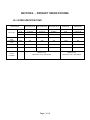
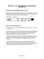
Light Tools - DC Screwdriver
Operation & Maintenance Manual
For Models:
SKD-2000L/UL/B, SKD-2200L/UL/B, SKD-2300L/UL/B
SKD-5200L/UL/B, SKD-5200P/UL/B
SKD-5300L/UL/B, SKD-5300P/UL/B
Dixon Automatic Tool Inc.
Products Group - Light Tools
2300 23rd Ave. Rockford IL 61104 U.S.A.
[email protected] • www.dixononline.com
OPERATION AND MAINTENANCE MANUAL
MODELS: SKD-2000L/UL/B, SKD-2200L/UL/B, SKD-2300L/UL/B,
SKD-5200L/UL/B, SKD-5200P/UL/B
SKD-5300L/UL/B, SKD-5300P/UL/B
FULLY AUTOMATIC
METAL ASSEMBLY SCREWDRIVERS
(UL)E16102
Metal Assembly Screwdrivers are designed for installing threaded fasteners in
light industrial and appliance manufacturing applications. Dixon Automatic Tool
Inc. is not responsible for customer modification of tools for applications on which
Dixon Automatic Tool Inc. was not consulted.
TABLE OF CONTENTS
Page
Title
Section 1 - Important Safety Instructions ........................................
1
Section 2 - Grounding Instructions ..................................................
5
Section 3 - Operator Cautions .......................................................
6
Section 4 - Product Specifications ..................................................
7
Section 5 - Bit Changing and Screwdriving Operation ...................
8
Section 6 - Torque Adjustment Operation .......................................
9
Section 7 - Product Accessories .....................................................
11
Section 8 - Servicing .......................................................................
12
Section 9 - Warranty .......................................................................
14
WARNING - READ ALL INSTRUCTIONS
Disconnect the Controller Power Cord from the receptacle before performing any
maintenance on this tool. Do not attempt to repair this tool unless you are a
Dixon authorized qualified electrician. When using electric tools, basic safety
precautions should always be followed to reduce the risk of fire, electric shock
and personal injury.
SECTION 1 - IMPORTANT SAFETY INSTRUCTIONS
1. Work Area:
1-1
Keep your work area clean and unobstructed.
- Cluttered and poorly lit work areas invite accidents.
1-2
Do not operate power tools in explosive atmospheres, such as in
the presence of flammable liquids, gases, or dust.
- Power tools create sparks which may ignite the dust or fumes.
1-3
Keep bystanders, children, and visitors away while operating a
power tool.
- Distractions can cause you to lose control of the tool.
2. Electrical Safety:
2-1
Grounded tools must be plugged into a properly installed outlet and
grounded in accordance with all codes and ordinances. Never
remove the grounding prong or modify the plug in any way. Do not
use adaptor plugs. Check with a qualified electrician if you think the
outlet may not be properly grounded.
-If the tool should electrically malfunction or break down, proper
grounding provides a low resistance path to carry electricity away
from the user.
2-2
Double insulated tools are equipped with a polarized plug (one
blade is wider than the other). This plug will only fit in a polarized
outlet one way. If the plug does not fully fit in the outlet, reverse the
plug. If the plug still does not fit, contact a qualified electrician to
install a polarized outlet. Do not change the plug in any way.
2-3
Do not expose power tools to rain or wet conditions.
- Water entering a power tool will increase the risk of electric shock.
2-4
Do not operate power tools in damp or wet locations.
- Operating tools in these conditions will increase the risk of electric
shock.
Page 1 of 14
2-5
Do not abuse the cord. Never use the cord to carry the tool or to
yank the tool from an outlet. Keep the cord away from heat, oil,
sharp edges, or moving parts. Immediately replace damaged cords.
- Damaged cords increase the risk of electric shock.
2-6
When operating a power tool outside, use an outdoor extension
cord marked "W-A" or "W".
- These cords are rated for outdoor use and reduce the risk of
electric shock.
3. Personal Safety:
3-1
Stay alert and use common sense while operating a power tool. Do
not use these tools while tired or under the influence of drugs,
alcohol, or medications.
- A moment of inattention while operating a power tool may result in
serious personal injury.
3-2
Dress properly. Do not wear loose clothing or jewelry. Tie back or
contain long hair. Keep your hair, clothing, and gloves away from
moving parts.
- Loose clothes, jewelry, or long hair can be caught in moving parts.
3-3
Avoid accidental starting. Be sure the switch is off before plugging
in the tool.
- Carrying tools, with your finger on the switch or plugging in tools
that have the switch "ON," invites accidents.
3-4
Remove adjusting keys or switches before turning the tool on.
- A wrench or a key that is left attached to a rotating part of the tool
may result in personal injury.
3-5
Do not overreach. Keep proper footing and balance at all times.
- Proper footing and balance enables better control of the tool in
unexpected situations.
3-6
Use safety equipment. Always wear eye protection.
- Dust masks, non-slip safety shoes, hard hats, or hearing
protection must be used when conditions warrant their use.
Page 2 of 14
4. Tool Use and Care:
4-1
Use clamps or other practical ways to secure and support the work
piece to a stable platform.
- Holding the work piece by hand or against your body is unstable
and may lead to loss of control and injury.
4-2
Do not force the tool. Use the correct tool for your application.
- Operate the tool within its design parameters. The correct tool will
do the job better and safer.
4-3
Do not use the tool if the power switch does not turn the tool on or
off.
- Any tool that cannot be controlled with the switch is dangerous
and must be repaired.
4-4
Disconnect the plug from the power source before making any
adjustments, changing accessories, or storing the tool.
- These preventive safety measures reduce the risk of the tool
accidentally starting.
4-5
Store idle tools out of reach of children and other untrained
persons.
- Tools are dangerous in the hands of untrained users.
4-6
Maintain tools with care and, in accordance with, standard industrial
practices.
- Properly maintain tools.
4-7
Check for misalignment or binding of moving parts, breakage of
parts, and any other condition that may affect the tool’s operation. If
the tool has any damage, have the tool serviced before using.
- Many accidents are caused by poorly maintained tools.
4-8
Use only accessories that are recommended by the manufacturer
for your model.
- Accessories that may be suitable for one tool may become
hazardous when used on another tool.
Page 3 of 14
5. Service:
5-1
Tool service must be performed only by qualified repair personnel.
- Service or maintenance performed by unqualified personnel could
result in a risk of injury.
5-2
When servicing a tool, use only factory provided replacement parts.
- Use of unauthorized parts or failure to follow maintenance
instructions may create a risk of electric shock or injury.
5-3
Check damaged parts.
- Before further use of the tool, all parts that are damaged should
be carefully checked to determine if the tool will still operate
properly and perform its intended function. Check for alignment and
binding of moving parts, for broken parts, for proper mounting, and
for any other condition that may adversely affect operation of the
tool. Any part that is damaged should be properly repaired or
replaced by an authorized service center, unless otherwise
indicated in this instruction manual. Have defective switches
replaced by an authorized service center. Do not use a tool if the
switch does not turn it on and off.
WARNING
The use of other than genuine Dixon Automatic Tool Inc. Light Tools
replacement parts may result in decreased tool performance and
increased maintenance, and may invalidate all warranties.
Page 4 of 14
SECTION 2 - GROUNDING INSTRUCTIONS
1. The tool should be grounded while in use to protect the operator from
electric shock. Notice! To ensure proper grounding, the grounding
conductor of the controller power cord must be well connected to the
grounding terminal of the power facility. The tool is equipped with a threeconductor cord and three-prong grounding-type plug to fit the proper
grounding-type receptacle. The green (or green and yellow) conductor in
the cord is the grounding wire. Never connect the green (or green and
yellow) wire to a line terminal.
Green and Yellow ----- Ground
Blue ------ Neutral
Brown ------ Line
2. Grounding of the tool is the most important precaution taken to protect
the user. Every 3-6 months use an Ohm meter to check the ground
connection. Follow these simple instructions: (a) set the Ohm meter level
to R*100 (Ohm), (b) touch the 2 testing probes ("+" & "-") together and
reset the meter to "0", and (c) use the Red ("+") probe to touch the ground
wire on the plug of tool’s cord, and the Black "-" probe to touch the end of
bit head. Grounding is normal if the meter reading is close to "0". To get a
normal indication from the meter while testing, the test probes must be
firmly pressed with both hands to the test points.
3. This tool has been tested at the factory by applying 26 amps to the
grounded metal. The ground resistance was equal to or less than 0.2
Ohms.
Page 5 of 14
SECTION 3 - OPERATOR CAUTIONS
1. When changing a bit, make certain the Forward / Reverse switch is in
the "OFF" position and the tool is unplugged.
2. Do not allow chemicals such as acetone, benzene, thinner,
trichloroethylene, ketone, or other similar chemicals to come in contact
with the screwdriver housing or damage will result.
3. Do not drop or abuse the screwdriver.
4. Do not adjust the torque setting higher than 8 on the torque scale.
5. There should be a tool rest interval of three seconds or longer. This tool
is intended for a cycle of 0.8 sec on, 3.2 sec off. Do not tighten more than
15 pieces per minute. Do not allow the motor to overload or overheat.
6. Do not tighten more than 900 self-tapping screws per hour.
7. Do not switch from Forward to Reverse while the motor is running.
8. Be sure the Forward / Reverse switch is in the "OFF" position before
connecting or disconnecting the screwdriver plug.
9. Whenever the tool is not being used or when changing accessories,
move the Forward / Reverse Switch to the "OFF" position and unplug the
screwdriver.
WARNING
Do not drop or abuse the tool.
Whenever a tool is not being used,
set the Power Switch to the "OFF"
position and unplug the power cord.
Page 6 of 14
SECTION 4 - PRODUCT SPECIFICATIONS
UL LISTED SPECIFICATIONS
SKD-2000L/UL/B
SKD-2200L/UL/B
SKD-2300L/UL/B
SKD-5200L/UL/B
5200P/UL/B
SKD-5300L/UL/B
5300P/UL/B
Kgf.cm
0.2-3.5
0.5-7
1-10
1-12
3-16
In-lb
0.18-3.08
0.44-6.16
0.88-8.8
0.88
2.64-14.08
Nm
0.02-0.34
0.05-0.69
0.1-0.98
0.1-1.18
0.29-1.57
Free Speed –
High
Free Speed –
Low
Length
Rpm
1000
1000
670
1000
1000
Rpm
700
700
470
1700
700
Mm
205
205
205
205
230
Weight
G
270
270
270
480
480
Model Number
Bit Torque
Power
Controller
SK-DU1/UL/A, SK-DU2/UL/A
Weight: 2.5 kg
Dimensions: 210 x 118 x 85mm
Page 7 of 14
SK-DU1/UL/A, SK-DU2/UL/A
Weight: 2.5 kg
Dimensions: 210 x 118 x 85mm
SECTION 5 – BIT CHANGING AND SCREWDRIVER
OPERATION
Attaching / Detaching Bits and Types of Bits:
Push the bit holder clamp up with your finger tip, and it will unlock the bit. The bit
can be freely attached and detached (single finger motion type). Select a power
drive hex bit with a shank equal to the size shown below.
Shape of Bit:
6.35mm Hex
Basic Screwdriver Operation:
Insert the power plug into a receptacle and set the direction switch to the forward
“F” position.
For a push-to-start type screwdriver, apply the bit to the screw head and push the
main body against the bit to start the motor running. The motor is turned "OFF"
when the torque level (set by the torque adjustment) is reached or when the
screwdriver is pulled back away from the screw head.
For a lever type screwdriver, apply the bit to the screw head. Then push the lever
to start the motor running. The motor is automatically turned "OFF" when the
torque level (set by the torque adjustment) is reached or when the lever is
released.
To remove a screw, (Dis-Assembly) set the Forward / Reverse switch to the
reverse "R" position, and use the method described above for your type of
screwdriver whether push-to-start or lever type. Note the torque level may need
to be increased to remove a screw once installed at its torque level.
Page 8 of 14
SECTION 6 - TORQUE ADJUSTMENT OPERATION
The screwdriver tightens a screw until the torque level set by the torque adjusting
ring is reached. When the torque level is reached, power is automatically
removed from the motor. To adjust the screwdriver's torque, follow the procedure
outlined below:
1. Increase or decrease the torque level by rotating the torque adjusting ring by
hand. Rotating the ring clockwise to a higher number increases the torque level.
Rotating the torque adjusting ring counterclockwise to a lower number decreases
the torque level.
2. Check the new torque level with a torque meter. The torque should be
checked for each job because a number of factors affect the torque output from
one job to another. The final torque level should be set using the actual job
pieces through a series of gradual torque increases. You should always start
below the desired torque level and work upward.
3. Since the torque output value is less than 9 in-lb, the torque of the SKD-2000,
SKD-2200 and SKD-2300 series screwdrivers can be measured with our KTM10/A Torque Meter. For the SKD-5200 and SKD-5300 series screwdrivers the
KTM-100/A Torque Meter is required because of the larger torque output values.
4. After using a torque meter to measure and adjust the torque of the
screwdriver, you may want to install a torque fixing ring accessory around the
torque adjusting ring. The torque fixing ring simply screws onto the housing of the
screwdriver. The torque fixing ring prevents operators from re-adjusting the
torque of the screwdriver. For further adjustments, the torque fixing ring must
first be removed.
5. Sometimes the Reverse “R” torque required to remove (Dis-Assembly) a
screw is larger than the torque that was used to tighten that screw. If the
tightened screw will not loosen easily, the clutch may skip or slip. If slipping does
occur, you must reset the screwdriver torque to a higher value to loosen the
screw.
Page 9 of 14
CAUTION
1. For reverse rotation, the clutch turns the motor off in the same manner it does
for the forward rotation. Accordingly, when a screw is tightened at a high torque,
and it cannot be backed out because the motor turns off, set the torque level to a
higher torque setting to back the screw out.
2. The numbers from zero to eight on the torque adjusting ring are reference only
numbers and not an exact indication of actual torque output.
3. The mechanical "clutch facing", or wear, of the SK series screwdrivers
depends on the torque output used on the tool, on the frequency the tool is used,
and on total usage time of the tool. The more the tool is used the more "facing"
occurs. A new tool set at a torque output level of 4, may experience a decline of
approximately 5-7% after being used for one month (a 7-10% decline may occur
if torque level is set at 8). However, the declining torque will become minor and
stabilized after about one month. To verify the torque output, the user should
check the torque output periodically with a torque meter and adjust the torque
upward 1-2 positions on the torque fixing ring scale to achieve the desired output.
To avoid arbitrary operator adjustments, the torque fixing ring accessory is
recommended when a torque adjustment is made.
Page 10 of 14
SECTION 7 - PRODUCT ACCESSORIES
The following items are included with each unit sold:
•
•
•
Two (2) Phillips 6.35mm (1/4”) Power Drive Hex Bits (length 65mm)
One (1) Spring (30cm) – used to hang up the screwdriver
Two (2) Carbon Brushes – as spare parts
Additional Accessories available for the SKD series models:
•
•
•
•
•
•
•
•
Torque Meter with Adapter
Handset Holder
Torque Fixing Ring
90 Degree Attachment (SKD-5200 & SKD-5300 Series only)
Suspend-All Hanger
Spring Balancer
Screw Setters
Idly Rotating Torque Driver
Page 11 of 14
SECTION 8 - SERVICING
Maintenance and Inspection:
1. The screwdriver must be operated in peak condition, and the working day
must not exceed more than eight hours.
2. Periodically check for wear of the motor's carbon brushes. If the brushes have
worn down by 2-3mm, replace them with a new brush assembly. Brush life
depends on the operation frequency and torque output. The greater the use and
higher the torque, the more rapidly the brushes will wear. Expect to replace the
brushes every 5-6 months.
3. When the total usage hours reach 1,000 hours or every 5-6 months: (a) clean
the tool's inner parts, (b) replace brushes with new brushes, (c) lubricate the gear
wheel, (d) inspect the cord assembly and armature, and (e) check if the ON/OFF
switch functions normally. This maintenance will extend the tool life and help
maintain torque accuracy.
4. Keep the motor dry and clean. Avoid the carbon build up that may decrease or
destroy the insulation.
5. Every 3-6 months lubricate the gear wheels with the recommended Magnalube
G grease. This will keep the gear assembly running smoothly and decrease the
facing of the clutch.
6. Please note - Do not let the motor get over heated. No more than 10 to 15
screws should be tightened each minute. The duty cycle for the tool is 1:4
(.8 seconds on and 3.2 seconds off).
Page 12 of 14
CAUTION
1. The use of other than genuine Dixon Automatic Tool Light Tools replacement
parts may result in decreased tool performance and increased maintenance, and
may invalidate all warranties.
2. All repairs of this tool must be performed by an authorized service center.
3. Dixon Automatic Tool Inc. is not responsible for customer modification of tools
for applications on which Dixon Automatic Tool Inc. was not consulted.
4. Repairs should be made only by authorized, trained personnel. Consult Dixon
Automatic Tool Inc. for service (815) 226-3000.
5. It is the responsibility of the employer to place the information in this manual
into the hands of the operator.
DO NOT ATTEMPT TO REPAIR THIS
METAL ASSEMBLY SCREWDRIVER
CAUTION
SAVE THESE INSTRUCTIONS
DO NOT DESTROY
Dixon Automatic Tool Inc.
Products Group - Light Tools
2300 23rd Avenue
Rockford, IL 61104-7370
Phone: 815-226-3000
Toll Free: 888-375-9444
www.dixonautomatic.com
Page 13 of 14
Warranty Terms & Conditions
1.
The "Company" refers to Dixon Automatic Tool, Inc. –
Light Tools free replacement of spare parts under normal usage except:
A.
B.
C.
D.
E.
F.
Bit
Spring Coil
Carbon Brush
External Case
Cord
Consumables
2.
Warranty will be voided if total usage is over 3000 hours, or which is 8 working
hours a day for a period of 1 year (whichever comes first).
3.
This warranty will be voided and null if:
A.
B.
C.
D.
E.
The product has been damaged by misuse, abnormal operation,
negligence, accident or Act of God.
It has been modified, altered and/or repaired by unauthorized person.
The serial number has been altered, effaced and/or removed.
The Company was not promptly informed of any change of address or the
ownership of the product.
Failing to use genuine parts (carbon brush, spare parts, etc.) sold or
recommended by the Company.
4.
The Company will not be liable for any loss directly or indirectly arising from
breakdown of the Product(s).
5.
Under this warranty, the Company only provides for service at Dixon Automatic
Tool during normal business hours. Should emergency service at Dixon
Automatic Tool be requested outside normal business hours, such service, if available,
will be provided and charged on a per call rate basis.
6.
The Warranty is not transferable without the consent of the Company.
7.
Contact the Company describing the function problem and obtain approval for
return of the product for final evaluation.
EXPRESS WARRANTY AND DISCLAIMERS
Any part of this equipment while in use by the buyer, which under normal operation or service proves defective in material or
workmanship as determined by seller's inspection after first returned to seller's factory, will be repaired or replaced free of charge
during a period of one year from the date of shipment from seller's factory.
Seller shall not be responsible for any change, modification, or alteration in the product after it leaves the seller. SELLER MAKES
NO EXPRESS OR IMPLIED WARRANTY OF FITNESS OR MERCHANT ABILITY OR ANY OTHER EXPRESSED OR
IMPLIED WARRANTY. THERE ARE NOT WARRANTIES WHICH EXTEND BEYOND THE FACE HEREOF. SELLER
SHALL NOT BE LIABLE FOR CONSEQUENTIAL, SPECIAL OR INDIRECT DAMAGES OF ANY NATURE, SUCH AS LOSS
OF BUSINESS OPERATION OR PROFITS FROM THE USE OR HANDLING OF THIS PRODUCT. THERE SHALL BE NO
VARIATION OR EXCEPTION FROM THIS WARRANTY UNLESS IN WRITING AND SIGNED BY OUR AUTHORIZED
REPRESENTATIVE. THE ABOVE IS IN LIEU OF ALL OTHER REMEDIES.
Page 14 of 14