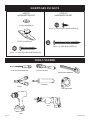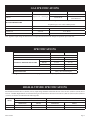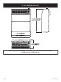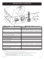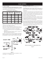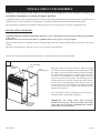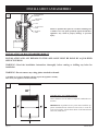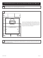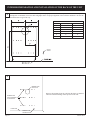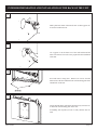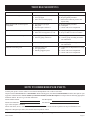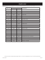
1
INSTALLATION
INSTRUCTIONS AND
OWNER'S MANUAL
DIRECT VENT
WALL FURNACE
STANDARD MODELS:
HWDV080DV(N,P)-1
HWDV181DV(N,P)-1
MODELS WITH BLOWER:
HWDV080BDV(N,P)-1
HWDV181BDV(N,P)-1
GAS-FIRED
Installer:
Leave this manual with the appliance.
Consumer: Retain this manual for future
reference.
WARNING: If the information in these instructions are not followed exactly, a fire
or explosion may result causing property
damage, personal injury or loss of life.
— Do not store or use gasoline or other flammable vapors and liquids in the vicinity of
this or any other appliance.
— WHAT TO DO IF YOU SMELL GAS
• Do not try to light any appliance.
• Do not touch any electrical switch; do
not use any phone in your building.
• Immediately call your gas supplier
from a neighbor’s phone. Follow the
gas supplier’s instructions.
• If you cannot reach your gas supplier,
call the fire department.
— Installation and service must be performed
by a qualified installer, service agency or
the gas supplier.
This appliance may be installed in an aftermarket, permanently located, manufactured
home (USA only), or mobile home, where not
prohibited by state or local codes.
This appliance is only for use with the type of
gas indicated on the rating plate. This appliance
is not convertible for use with other gases.
WARNING: If not installed, operated, and
maintained in accordance with the manufacturer's instructions, this product could expose you
to substances in fuel or from fuel combustion
which can cause death or serious illness.
DO NOT RETURN THIS PRODUCT TO
THE STORE WHERE YOU PURCHASED
IT. IF YOU ARE MISSING PARTS, OR
HAVE ANY PROBLEMS, CONTACT
EMPIRE COMFORT SYSTEMS INC. AT
(877) 459-1583.
Page 1
TABLE OF CONTENTS
SECTION
PAGE
Included in the Box .................................................................................................. 3
Hardware Packets .................................................................................................... 4
Tools Needed ............................................................................................................. 4
Gas Specifications .................................................................................................... 5
Specifications ............................................................................................................ 5
High Altitude Specifications .................................................................................... 5
Unit Dimensions ....................................................................................................... 6
Important Safety Information ................................................................................ 7
Safety Information for Users of LP-Gas ................................................................ 8
Introduction .............................................................................................................. 9
Requirements for Massachusetts .......................................................................... 10
Termination Clearances ......................................................................................... 11
Gas Supply ......................................................................................................... 12-13
Clearances ............................................................................................................... 13
Installation Instructions Overview ....................................................................... 14
Installation and Assembly ................................................................................ 15-16
Interior Preparation and Installation of the Back of the Unit ...................... 17-19
Interior Installation of the Front of the Unit ....................................................... 20
Cutting the Vent Tubes ..................................................................................... 21-22
Exterior Installation of the Venting ................................................................. 23-25
Reassembly and Resealing Vent-Air Intake System ...................................... 26-28
Installation of Optional Blower Kit HW125SCB ........................................... 29-32
Before Operating Appliance ............................................................................. 33-36
Operating Instructions .......................................................................................... 37
Lighting Instructions ............................................................................................. 38
To Turn Off Gas to Appliance ............................................................................... 38
Pilot Flame Characteristics ................................................................................... 39
Main Burner Flame Characteristics .................................................................... 39
Maintenance Instructions ...................................................................................... 40
Troubleshooting ...................................................................................................... 41
How To Order Repair Parts .................................................................................. 41
Parts List ............................................................................................................ 42-43
Parts View ............................................................................................................... 44
Service Notes ...................................................................................................... 45-47
Page 2
24632-0-0508
INCLUDED IN THE BOX
DIRECT VENT HEATER
(INSIDE WALL MOUNTING PLATE
ATTACHED ON BACK)
HEATER
HARDWARE PACKET
VENT SHIELD
24632-0-0508
INSTALLATION TEMPLATE
(TEMPLATE FOR HWDV080
ON REVERSE SIDE)
VENT KIT
HARDWARE PACKET
OUTSIDE WALL MOUNTING PLATE
& VENT CAP
INLET & OUTLET TUBES
Page 3
HARDWARE PACKETS
VENT KIT
HARDWARE PACKET
HEATER
HARDWARE PACKET
NYLON WASHER (2)
#10 X ½” PHILLIPS HEX HEAD SCREW (3)
PLASTIC TOGGLE (6)
#10 X 2 ½” HEX HEAD SCREW (4)
#10 X 1 ½” SLOTTED HEX HEAD SCREW (6)
TOOLS NEEDED
PHILLIPS SCREW DRIVER
SNIPS
5/16 NUT DRIVER
ADJUSTABLE WRENCH
CAULKING
TAPE MEASURE
SAW
DRILL
Page 4
24632-0-0508
GAS SPECIFICATIONS
MODEL
FUEL
HW080
MAXIMUM INPUT
MINIMUM INPUT
8,000 Btu/hr
Propane/LP -- Natural gas
HW181
MANIFOLD PRESSURE
5,000 Btu/hr
9,000 Btu/hr NAT
18,000 Btu/hr
9,500 Btu/hr LP
Natural gas: 4" water column pressure
Propane/LP gas: 10.0" water column pressure
3/8"
MINIMUM PRESSURE
MAXIMUM PRESSURE
5" W.C.P.
10.5" W.C.P.
11" W.C.P.
13" W.C.P.
Gas Inlet
SUPPLY
Natural Gas
LP Gas
Note: Appliance input ratings are based on sea level operation and need not be changed for operation up to 2,000 feet.
SPECIFICATIONS
MODELS
HWDV080(B)DV
COMBUSTION
STANDARD HEATING SPACE
EXTERNAL DIMENSIONS INCHES
NET WEIGHT LBS.
MAX. GAS CONSUMPTION
SAFETY DEVICES
HEIGHT
WIDTH
DEPTH
HWDV181(B)DV
ATMOSPHERIC BURNER
85 - 250 Sq. Ft.
169 - 529 Sq. Ft.
21 11/16"
25 3/16"
18 5/16"
22 5/16"
8 7/8"
9 3/8"
33.5
45.5
8,000 Btu/hr.
18,000 Btu/hr.
Safety valve (thermocouple)
Warning: This direct vent wall furnace is equipped for Natural or Propane gas. Field conversion is not permitted.
HIGH ALTITUDE SPECIFICATIONS
For altitudes/elevations above 2,000 feet (610 m), input ratings should be reduced at the rate of 4% for each 1,000 feet (305 m) above
sea level. Canadian High Altitudes for locations having an elevation above mean sea level between 2,000 feet (609.9 m) and 4,500 feet
(1,370 m), use orifices as indicated in the following table:
Model
HW080
HW181
24632-0-0508
0 - 2,000 feet (0 - 610 m)
Main Burner Orifice/Gas Pressure
Natural Gas
LP Gas
#55 (4")
#66 (10")
#49 (4")
#56 (10")
2,000 - 4,500 feet (610 - 1 370 m)
Main Burner Orifice/Gas Pressure
Natural Gas
LP Gas
#1.27 mm (4")
#67 (10")
#50 (4")
#57 (10")
Page 5
UNIT DIMENSIONS
MAKE SURE THAT APPLIANCE IS SUITABLE FOR THE GAS SUPPLY AVAILABLE:
NATURAL GAS OR PROPANE/LP.
Page 6
24632-0-0508
IMPORTANT SAFETY INFORMATION
Children and adults should be alerted to the hazards of high surface temperatures and should stay
away to avoid burns or clothing ignition.
Any safety screen or guard removed for servicing
must be replaced prior to operating the heater.
Do not use this heater if it has been under water.
Immediately call a qualified service technician to
inspect the heater and to replace any part of the
control system and any gas control which has been
under water.
Young children should be carefully supervised when
they are in the same room as the heater.
Installation and repair should be done by a qualified service person. Heater should be inspected before use and at least annually by a qualified service
person.
More frequent cleaning may be required due to excessive lint from carpeting, bedding material etc. It
is imperative that control compartments, burners,
and circulating air passageways of the appliance be
kept clean.
Follow State and Local codes for installation.
DO NOT put anything around or on top of the furnace that will obstruct the flow of combustion and
ventilation air.
DO keep the appliance area clear and free from
combustible material, gasoline and other flammable vapors and liquids.
DO examine venting system periodically and replace damaged parts.
DO make a periodic visual check of pilot and burners. Clean and replace damaged parts.
CAUTION: Pilot hole cover must be kept tightly
closed during operation.
Vent cap hot while furnace is in operation.
24632-0-0508
Page 7
SAFETY INFORMATION FOR USERS OF LP-GAS
Propane (LP-Gas) is a flammable gas which can cause fires
and explosions. In its natural state, propane is odorless and
colorless. You may not know all the following safety precautions
which can protect both you and your family from an accident.
Read them carefully now, then review them point by point
with the members of your household. Someday when there
may not be a minute to lose, everyone's safety will depend on
knowing exactly what to do. If, after reading the following
information, you feel you still need more information, please
contact your gas supplier.
LP-GAS WARNING ODOR
•
•
•
•
If a gas leak happens, you should be able to smell the gas because of the odorant put in the LP-Gas.
That's your signal to go into immediate action!
• Use your neighbor's phone and call a trained LP-Gas service
Do not operate electric switches, light matches, use your
person and the fire department. Even though you may not
phone. Do not do anything that could ignite the gas.
continue to smell gas, do not turn on the gas again. Do not
Get everyone out of the building, vehicle, trailer, or area. Do
re-enter the building, vehicle, trailer, or area.
that IMMEDIATELY.
Close all gas tank or cylinder supply valves.
• Finally, let the service man and firefighters check for escaped
LP-Gas is heavier than air and may settle in low areas such
gas. Have them air out the area before you return. Properly
as basements. When you have reason to suspect a gas leak,
trained LP-Gas service people should repair the leak, then
keep out of basements and other low areas. Stay out until
check and relight the gas appliance for you.
firefighters declare them to be safe.
NO ODOR DETECTED - ODOR FADE
Some people cannot smell well. Some people cannot smell the
odor of the chemical put into the gas. You must find out if you
can smell the odorant in propane. Smoking can decrease your
ability to smell. Being around an odor for a time can affect your
sensitivity or ability to detect that odor. Sometimes other odors
in the area mask the gas odor. People may not smell the gas odor
or their minds are on something else. Thinking about smelling a
gas odor can make it easier to smell.
The odorant in LP-gas is colorless, and it can fade under some
circumstances. For example, if there is an underground leak, the
movement of the gas through soil can filter the odorant. Odorants
in LP-Gas also are subject to oxidation. This fading can occur if
there is rust inside the storage tank or in iron gas pipes.
The odorant in escaped gas can adsorb or absorb onto or into walls,
masonry and other materials and fabrics in a room. That will take
some of the odorant out of the gas, reducing its odor intensity.
LP-Gas may stratify in a closed area, and the odor intensity could
vary at different levels. Since it is heavier than air, there may be
more odor at lower levels. Always be sensitive to the slightest gas
odor. If you detect any odor, treat it as a serious leak. Immediately
go into action as instructed earlier.
SOME POINTS TO REMEMBER
•
Learn to recognize the odor of LP-gas. Your local LP-Gas
Dealer can give you a "Scratch and Sniff" pamphlet. Use it
to find out what the propane odor smells like. If you suspect
that your LP-Gas has a weak or abnormal odor, call your
LP-Gas Dealer.
•
If you are not qualified, do not light pilot lights, perform
service, or make adjustments to appliances on the LP-Gas
system. If you are qualified, consciously think about the odor
of LP-Gas prior to and while lighting pilot lights or performing service or making adjustments.
•
Sometimes a basement or a closed-up house has a musty
smell that can cover up the LP-Gas odor. Do not try to light
pilot lights, perform service, or make adjustments in an area
where the conditions are such that you may not detect the
odor if there has been a leak of LP-Gas.
•
Odor fade, due to oxidation by rust or adsorption on walls
of new cylinders and tanks, is possible. Therefore, people
should be particularly alert and careful when new tanks or
cylinders are placed in service. Odor fade can occur in new
tanks, or reinstalled old tanks, if they are filled and allowed
Page 8
to set too long before refilling. Cylinders and tanks which
have been out of service for a time may develop internal rust
which will cause odor fade. If such conditions are suspected
to exist, a periodic sniff test of the gas is advisable. If you
have any question about the gas odor, call your LP-gas dealer.
A periodic sniff test of the LP-gas is a good safety measure
under any condition.
•
If, at any time, you do not smell the LP-Gas odorant and you
think you should, assume you have a leak. Then take the same
immediate action recommended above for the occasion when
you do detect the odorized LP-Gas.
•
If you experience a complete "gas out," (the container is under no vapor pressure), turn the tank valve off immediately.
If the container valve is left on, the container may draw in
some air through openings such as pilot light orifices. If this
occurs, some new internal rusting could occur. If the valve is
left open, then treat the container as a new tank. Always be
sure your container is under vapor pressure by turning it off
at the container before it goes completely empty or having it
refilled before it is completely empty.
24632-0-0508
INTRODUCTION
Always consult your local Building Department regarding regulations, codes or ordinances which apply to the installation of a
direct vent wall furnace.
Instructions to Installer
1. Installer must leave instruction manual with owner after installation.
2. Installer must have owner fill out and mail warranty card supplied with furnace.
3. Installer should show owner how to start and operate furnace
and thermostat.
Warning:
Any change to this furnace or its control can be dangerous. This is a heating appliance and any panel, door or
guard removed for servicing an appliance must be replaced prior to operating the appliance.
General Information
This furnace is design certified in accordance with American National Standard/CSA Standard Z21.86 and CSA 2.32 by Underwriters Laboratory as a direct vent wall furnace to be installed
according to these instructions.
Any alteration of the original design, installed other than as
shown in these instructions or use with a type of gas not shown
on the rating plate is the responsibility of the person and company making the change.
Notice: During initial firing of this unit, its paint will bake out and
smoke will occur. To prevent triggering of smoke alarms, ventilate the room in which the unit is installed.
Installation in Residential Garages
Gas utilization equipment in residential garages shall be installed
so that all burners and burner ignition devices are located not
less than 18" above the floor. Such equipment shall be located,
or protected, so it is not subject to physical damage by a moving
vehicle.
24632-0-0508
Qualified Installing Agency
Installation and replacement of gas piping, gas utilization equipment or accessories and repair and servicing of equipment shall
be performed by a qualified agency. The term “qualified agency”
means any individual, firm, corporation or company which either
in person or through a representative is engaged in and is responsible for (1) the installation or replacement of gas piping or (2) the
connection, installation, repair or servicing of equipment, who is
experienced in such work, familiar with all precautions required
and has complied with all the requirements of the authority having jurisdiction.
State of Massachusetts: The installation must be made by a
licensed plumber or gas fitter in the Commonwealth of Massachusetts. The state of Massachusetts requires that a flexible
appliance connector cannot exceed three feet in length.
The installation must conform with local codes or, in the absence
of local codes, with the National Fuel Gas Code ANSI Z223.1/
NFPA 54* Natural Gas and Propane Installation Code, CSA
B149.1.
*Available from the American National Standards Institute, Inc., 11 West 42nd St.,
New York, N.Y. 10036.
The vent terminal of a direct vent appliance, with an input of
10,000 Btu per hour (3 kW) or less shall be located at least 6"
(150 mm) from any air opening into a building, and such an appliance with an input over 10,000 Btu per hour (3 kW) but not
over 50,000 Btu per hour (14.7 kW) shall be installed with a 9"
(229 mm) vent terminal clearance and the bottom of the vent terminal and the air intake shall be located at least 12" (305 mm)
above grade.
WARNING: The nearest point of the vent cap should be a
minimum horizontal distance of six (6) feet (1.8 m) from
any pressure regulator. In case of regulator malfunction,
the six (6) feet (1.8 m) distance will reduce the chance of
gas entering the vent cap.
Page 9
REQUIREMENTS FOR MASSACHUSETTS
For all side wall horizontally vented gas fueled equipment installed
in every dwelling, building or structure used in whole or in part
for residential purposes, including those owned or operated by the
Commonwealth and where the side wall exhaust vent termination
is less than seven (7) feet above finished grade in the area of the
venting, including but not limited to decks and porches, the following requirements shall be satisfied:
1.
INSTALLATION OF CARBON MONOXIDE DETECTORS.
At the time of installation of the side wall horizontal vented
gas fueled equipment, the installing plumber or gasfitter shall
observe that a hard wired carbon monoxide detector with an
alarm and battery back-up is installed on the floor level where
the gas equipment is to be installed. In addition, the installing
plumber or gasfitter shall observe that a battery operated or
hard wired carbon monoxide detector with an alarm is installed
on each additional level of the dwelling, building or structure
served by the side wall horizontal vented gas fueled equipment.
It shall be the responsibility of the property owner to secure the
services of qualified licensed professionals for the installation
of hard wired carbon monoxide detectors.
(a) In the event that the side wall horizontally vented gas
fueled equipment is installed in a crawl space or an attic,
the hard wired carbon monoxide detector with alarm and
battery back-up may be installed on the next adjacent floor
level.
(b) In the event that the requirements of this subdivision can
not be met at the time of completion of installation, the
owner shall have a period of thirty (30) days to comply
with the above requirements; provided, however, that during said thirty (30) day period, a battery operated carbon
monoxide detector with an alarm shall be installed.
2.
APPROVED CARBON MONOXIDE DETECTORS. Each
carbon monoxide detector as required in accordance with the
above provisions shall comply with NFPA 720 and be ANSI/UL
2034 listed and IAS certified.
Page 10
3.
SIGNAGE. A metal or plastic identification plate shall be permanently mounted to the exterior of the building at a minimum
height of eight (8) feet above grade directly in line with the
exhaust vent terminal for the horizontally vented gas fueled
heating appliance or equipment. The sign shall read, in print
size no less than one-half (1/2) inch in size, “GAS VENT
DIRECTLY BELOW. KEEP CLEAR OFALL OBSTRUCTIONS”.
4.
INSPECTION. The state or local gas inspector of the side wall
horizontally vented gas fueled equipment shall not approve
the installation unless, upon inspection, the inspector observes
carbon monoxide detectors and signage installed in accordance
with the provisions of 248 CMR 5.08(2)(a) 1 through 4.
(b) EXEMPTIONS: The following equipment is exempt from
248 CMR 5.08(2)(a)1 through 4:
1. The equipment listed in Chapter 10 entitled “Equipment Not Required To Be Vented” in the most current
edition of NFPA 54 as adopted by the Board; and
2. Product Approved side wall horizontally vented gas
fueled equipment installed in a room or structure
separate from the dwelling, building or structure used
in whole or in part for residential purposes.
(c) MANUFACTURER REQUIREMENTS - GAS EQUIPMENT VENTING SYSTEM PROVIDED. When the
manufacturer of Product Approved side wall horizontally
vented gas equipment provides a venting system design
or venting system components with the equipment, the
instructions provided by the manufacturer for installation
of the equipment and the venting system shall include:
1. Detailed instructions for the installation of the venting system design or the venting system components;
and
2. A complete parts list for the venting system design
or venting system.
(e) A copy of all installation instructions for all Product Approved side wall horizontally vented gas fueled equipment,
all venting instructions, all parts lists for venting instructions, and/or all venting design instructions shall remain
with the appliance or equipment at the completion of the
installation.
24632-0-0508
TERMINATION CLEARANCES
A
B
C
D
E
F
G
H
I
J
Description
Clearance above grade, veranda, porch, deck, or balcony
Clearance to window or door that may be open
Clearance to permanently closed window
Vertical clearance to ventilated soffit located above the
terminal within a horizontal distance of 2 feet (610 mm)
from the center line of the terminal
Clearance to unventilated soffit
Clearance to outside corner
Clearance to inside corner
Clearance to each side of center line extended above meter/regulator assembly
Clearance to service regulator vent outlet
Clearance to non-mechanical air supply inlet to building
or the combustion air inlet to any other appliance.
K
L
US Installations1
12 inches (305 mm)
6 inches (152 mm) for appliance ≤ 10,000 Btuh (3 kW), 9 inches
(229 mm) for appliances > 10,000 Btuh (3 kW) and ≤ 50,000 Btuh
(15 kW), 12 inches (305 mm) for appliances > 50,000 Btuh (15 kW)
*
*
*
24"
24"
*
*
6 inches (152 mm) for appliance ≤ 10,000 Btuh (3 kW), 9 inches
(229 mm) for appliances > 10,000 Btuh (3 kW) and ≤ 50,000 Btuh
(15 kW), 12 inches (305 mm) for appliances > 50,000 Btuh (15 kW)
3 feet (914 mm) above if within 10 feet (3.04 m) horizontally
*
Clearance to a mechanical air supply inlet
Clearance above paved sidewalk or paved driveway located on public property
M Clearance under veranda, porch, deck, or balcony.
*
The minimum distance from the center of the outside vent to the nearest inside and outside corner or obstruction or overhang is 24"
(457 mm).
1
In accordance with current ANSI Z223.1/NFPA 54, National Fuel Gas Code
* For clearances not specified in ANSI Z223.1/NFPA 54 or CSA B149.1, one of the following shall be indicated:
a) A minimum clearance value determined by testing in accordance with section 2.19.6, or;
b) A reference to the following footnote:
“Clearance in accordance with local installation codes and the requirements of the gas supplier.”
24632-0-0508
Page 11
GAS SUPPLY
Locating Gas Supply
The gas line can enter the unit either through the floor or outside
wall. The gas line opening should be made at this time. Location
of the opening will be determined by the position of floor joists
and the valve and union used for servicing.
Recommended Gas Pipe Diameter
Pipe Length
Schedule 40 Pipe
Tubing, Type L
Inside Diameter
Outside Diameter
Nat.
L.P.
Nat.
L.P.
0-10 feet
1/2”
3/8”
1/2”
3/8”
0-3 meters
12.7 mm
9.5 mm
12.7 mm
9.5 mm
10-40 feet
1/2”
1/2”
5/8”
1/2”
4-12 meters 12.7 mm 12.7 mm 15.9 mm 12.7 mm
40-100 feet
1/2”
1/2”
3/4”
1/2”
13-30 meters 12.7 mm 12.7 mm
19 mm
12.7 mm
100-150 feet
3/4”
1/2”
7/8”
3/4”
31-46 meters
19 mm
12.7 mm 22.2 mm
19 mm
Note: Never use plastic pipe. Check to confirm whether your local
codes allow copper tubing or galvanized.
Note: Since some municipalities have additional local codes, it is
always best to consult your local authority and installation code.
The use of the following gas connectors is recommended:
— ANS Z21.24 Appliance Connectors of Corrugated Metal Tubing
and Fittings
— ANS Z21.45 Assembled Flexible Appliance Connectors of
Other Than All-Metal Construction
The above connectors may be used if acceptable by the authority
having jurisdiction. The state of Massachusetts requires that a
flexible appliance connector cannot exceed three feet in length.
Installing a New Main Gas Cock
Each appliance should have its own manual gas cock.
A manual main gas cock should be located in the vicinity of
the unit. Where none exists, or where its size or location is not
adequate, contact your local authorized installer for installation
or relocation.
Compounds used on threaded joints of gas piping shall be resistant
to the action of liquefied petroleum gases. The gas lines must be
checked for leaks by the installer. This should be done with a soap
solution watching for bubbles on all exposed connections, and if
unexposed, a pressure test should be made.
Never use an exposed flame to check for leaks. Appliance must be
disconnected from piping at inlet of control valve and pipe capped
or plugged for pressure test. Never pressure test with appliance
connected; control valve will sustain damage!
A gas valve and ground joint union should be installed in the gas
line upstream of the gas control to aid in servicing. It is required
by the National Fuel Gas Code that a drip line be installed near
the gas inlet. This should consist of a vertical length of pipe tee
connected into the gas line that is capped on the bottom in which
condensation and foreign particles may collect.
FLEXIBLE GAS LINE CONNECTION
GAS SUPPLY
TEE HANDLE
NPT NIPPLE
REGULATOR
FLEX TUBE
FLARE SHUT OFF VALVE
VALVE
FLARE FITTING
RIGID GAS LINE CONNECTION
CLOSE NIPPLE
3/8 NIPPLE
TEE HANDLE
SHUT OFF VALVE
NPT GAS SUPPLY
REGULATOR
VALVE
NPT UNION
Method of Installing a Tee Fitting Sediment Trap
Figure 2
Figure 1
Consult the current National Fuel Gas Code, ANSI Z223.1 CAN/
CGA-B149 (.1 or .2) installation code.
Page 12
24632-0-0508
GAS SUPPLY (continued)
Pressure Testing of the Gas Supply System
1. To check the inlet pressure to the gas valve, a 1/8" (3 mm) N.P.T.
plugged tapping, accessible for test gauge connection, must be
placed immediately upstream of the gas supply connection to
the appliance.
2. The appliance and its individual shutoff valve must be
disconnected from the gas supply piping system during any
pressure testing of that system at test pressures in excess of
1/2 psig (3.5 kPa).
3. The appliance must be isolated from the gas supply piping
system by closing its individual manual shutoff valve during
any pressure testing of the gas supply piping system at test
pressures equal to or less than 1/2 psig (3.5 kPa).
Attention! If one of the above procedures results in pressures in
excess of 1/2 psig (14" w.c.) (3.5 kPa) on the appliance gas valve,
it will result in a hazardous condition.
Checking Manifold Pressure
Both Propane and Natural have a pressure regulator attached to
the gas valve. Natural gas models will have a manifold pressure
of approximately 4.0" w.c. (.996 kPa) at the valve outlet with
the inlet pressure to the valve from a minimum of 5.0" w.c.
(1.245 kPa) for the purpose of input adjustment to a maximum of
10.5" w.c. (2.61 kPa). Propane gas models will have a manifold
pressure approximately 10.0" w.c. (2.49 kPa) at the valve
outlet with the inlet pressure to the valve from a minimum of
11.0" w.c. (2.739 kPa) for the purpose of input adjustment to a
maximum of 13.0" w.c. (3.237 kPa).
A 1/8" (3 mm) N.P.T. plugged tapping, accessible for test gauge
connection, is located on the side of the gas pressure regulator.
CLEARANCES
1. In selecting a location for installation, it is necessary to provide
adequate accessibility clearances for servicing and proper
installation.
2. Unit is supported by a wall bracket secured to the wall.
3. The minimum clearances from casing to combustible construction
is 36" (914.4 mm) on top, 6" (152 mm) on each side and
4" (102 mm) from the floor or from the top surface of carpeting,
tile or other floor covering and 0" (0 mm) to rear wall.
4. The minimum distance from the center of the vent cap to the
nearest outside corner or obstruction is 24" (610 mm).
5. The minimum wall depth is 4 1/2" (114.3 mm) and the
maximum is 12" (304.8 mm). The use of tubes not supplied
by the manufacturer results in unsatisfactory performance.
WARNING: The nearest point of the vent cap should be a
minimum horizontal distance of six (6) (1.83m) feet from
any pressure regulator. In case of regulator malfunction, the
six (6) foot (1.83m) distance will reduce the chance of gas
entering the vent cap.
The vent terminal of a direct vent appliance, with an input of
50,000 (14.6 KW) BTU per hour or less shall be located at least 9"
(229 mm) from any opening through which flue gases could enter
a building. The bottom of the vent terminal and the air intake shall
be located at least 12" (305 mm) above grade.
The vent terminal of a direct vent appliance, with an input of
10,000 Btu per hour (3 kW) or less shall be located at least 6"
(150 mm) from any air opening into a building, and such an appliance with an input over 10,000 Btu per hour (3 kW) but not
over 50,000 Btu per hour (14.7 kW) shall be installed with a 9"
(229 mm) vent terminal clearance and the bottom of the vent terminal and the air intake shall be located at least 12" (305 mm)
above grade.
24632-0-0508
Page 13
INSTALLATION INSTRUCTIONS OVERVIEW
Location - All Models
Select a location near the center of the space to be heated. Overflow
heat will circulate through doorways into adjacent rooms.
The furnace is to be located on an outside wall. Locate wall studs
so that wall opening will be located between wall studs. One wall
stud can be used for attachment of inside wall plate. The wall
opening required as shown in Figure 3 is a minimum diameter of
6 1/4" (159 mm). The inside wall plate and the outside wall plate are
large enough to permit a wall opening diameter of 8" (203 mm).
A template is provided in furnace carton for positioning furnace
on the wall. Also, refer to Figure 3 for positioning the furnace on
wall and for locating gas line connection.
For large homes or spread-out floor plans, two or more furnaces
are recommended.
Do not locate furnace where a door could swing over the outer
casing, or where circulation could be retarded by furniture or
cabinets. See Figure 4.
Do not install in a closet, alcove or small hallway where the furnace
could be isolated by closing doors to the heated space. See Figures
5 and 6.
When location is selected, check the walls to make sure there are
no obstructions such as pipes, electric wiring, etc., which would
interfere with the installation of the furnace or vent pipe.
See Page 18, Box 4 for dimensions.
Figure 3
Figure 4
Page 14
Figure 5
Figure 6
24632-0-0508
INSTALLATION AND ASSEMBLY
WARNING: Any change to this heater or its control can be dangerous. Provide adequate clearances and
accessibility for purposes of servicing and proper operation.
A manufactured home (USA only) installation must conform with the Manufactured Home Construction and Safety Standard, Title 24
CFR, Part 3280 or, when such standard is not applicable, the Standard for Manufactured Home Installations, ANSI Z225.1.
Due to high surface temperature, keep children, clothing, and furniture away. Keep burner and control compartments clean.
INSTALLATION OVERVIEW
WARNING: Improper installation, adjustments, alteration, service, or maintenance can cause property damage, personal injury
or loss of life.
Installation and service must be performed by a qualified installer, service agency, or the gas supplier.
These wall furnace models are designed for direct venting through a wall. Only venting components approved for these furnaces may
be used.
This unit is to be installed on a wall from 4 1/2" to 12" (114.3 mm to 304.8 mm) thick.
Note: All references must be considered as if the observer is standing in front of the wall and/or appliance.
1
WALL
MOUNTING
SCREWS
WALL MOUNTING
PLATE
WALL
MOUNTING TAB
Mark the venting system hole location (as indicated on page
18) and the six holes through the wall mounting plate. Drill
accordingly. Insert the four wall anchors provided and tighten
the wall mounting plate firmly. Use special anchor fasteners if
the heater is to be installed on a wooden (hollow) wall. Line
up the two (2) tabs on the top of the wall mounting plate with
the holes in the back of the unit. Slide the back of the unit onto
the tabs of the wall mounting plate. Secure the back of the unit
into place using two (2) screws. Replace casing door. The heater
is now ready to receive the venting system assembly from the
opposite side of the wall.
Note: All references must be considered as if the observer is
standing in front of the wall and/or appliance.
HEATER TO
BACK CASING
MOUNTING
SCREWS
24632-0-0508
IMPORTANT: The venting system must be properly
installed to insure proper and safe operation. The venting
system must also be properly re-installed and re-sealed to
insure proper and safe operation.
Page 15
INSTALLATION AND ASSEMBLY
2
SILICON-BASED
SEALANT
MOUNTING
PLATE
CAP
FLUE OUTLET
TUBE
AIR INLET
TUBE
Failure to position these parts in accordance with diagram
or failure to use only parts specifically approved with these
appliances may result in property damage or personal
injury.
INSTALLATION OF HOUSEWARMER PRODUCT
INSTALLATION AND ANY REPAIRS TO THIS APPLIANCE MUST BE DONE BY A QUALIFIED
SERVICE PERSON.
WARNING: Read the installation instructions thoroughly before cutting or drilling any holes for
installation.
WARNING: Do not remove any rating plates attached to the unit.
A qualified service person should be called to inspect this appliance annually.
Have all of your appliances checked annually.
3
CLEARANCES TO COMBUSTIBLES
Allow clearances (for all models) to adjacent combustible construction.
IMPORTANT: A qualified service person must install this appliance. Installation must conform to local codes, or in the absence of local codes, with the latest edition of the National Fuel
Gas Code, ANSI Z223.1.
Page 16
24632-0-0508
INTERIOR PREPARATION AND INSTALLATION OF THE BACK OF THE UNIT
1
Before installing unit, remove wall mounting plate from back of unit.
2
MOUNTING TEMPLATE FOR
Locate the wall mounting plate template included in your kit
and remove the perforated sections. Use painters tape to secure
the wall mounting plate template onto the interior wall where
the heater will be located. (Template for HWDV080 will be on
the opposite side of the shown template.)
SEE OTHER SIDE FOR HWDV080
3
Trace the template wall hole and (if applicable) the gas inlet hole onto the wall. Mark the six (6) wall mounting plate screw
holes onto the wall. The size of the gas inlet hole will depend upon the size of gas pipe coming into the unit. (See page 17,
box 2 and page 18, box 4).
24632-0-0508
Page 17
INTERIOR PREPARATION AND INSTALLATION OF THE BACK OF THE UNIT
4
Housewarmer recommends the use of the wall template to properly cut the wall holes and place the heater. If the template is
damaged or not included, refer to the table and graphic below for proper alignment of the wall holes and heater.. Be sure the
baseboard does not get in the way.
MEASUREMENTS
Model
HWDV080(B)DV
HWDV181(B)DV
C
7 3/8"
11 3/8"
D
10 7/8"
10 7/8"
E
21"
24 1/2"
F
9 1/4"
9 1/4"
G
4"
4"
I
6 1/4"
6 1/4"
5
MARKING FOR
WALL HOLE
Remove the template from the wall after the holes are marked.
The hole location markings will be present on the wall.
MARKING FOR
WALL MOUNTING
PLATE HOLES
FLOOR LINE
MARKING FOR
GAS INLET HOLE
Page 18
24632-0-0508
INTERIOR PREPARATION AND INSTALLATION OF THE BACK OF THE UNIT
6
Pilot
Hole
Drill a pilot hole inside of the traced circle so that a jigsaw can
be used to cut the holes out.
7
Use a jigsaw to cut the holes out of the wall and discard the
inner circle debris. The wall is now prepared for the installation
of the unit.
8
Pivot and remove casing door. Remove two screws from the
back inside of the unit and detach the wall mounting plate from
outside back of the unit.
9
Locate the studs in the wall and use at least four (4) wood screws
to attach the wall mounting plate to the wall.
If installing onto drywall (not into a stud), anchors must be
used.
24632-0-0508
Page 19
INTERIOR INSTALLATION OF THE FRONT OF THE UNIT
1
Line up the two (2) tabs on the top of the wall mounting plate
with the holes in the back of the unit. Slide the back of the unit
onto the tabs of the wall mounting plate.
2
Secure the back of the unit into place using two (2) screws.
Replace casing door.
3
GAS LINE
After the back of the unit is attached to the wall, bring in the
gas line as shown on page 18, or follow the installation template
indications. Following your city, local and state codes, attach the
gas line to the unit.
NOTE: The gas line runs through the wall or floor of the
house..
Page 20
24632-0-0508
CUTTING THE VENT TUBES
NOTE: Flue outlet tube and air inlet tube should be measured and cut to the proper length from the back of the unit to the outside wall
of the house. See page 22, boxes 3 and 4.
IMPORTANT: The appliance’s venting system should be inspected at least once a year and immediately cleaned if necessary.
1
FLUE OUTLET TUBE
AIR INLET TUBE
MOUNTING PLATE
CAP
LONG SCREWS (4X)
SCREWS (3X)
2
4 1/2” to 12”
THICK WALL
This unit is to be installed on wall from 4 1/2" to 12" (114.3 mm to 304.8 mm) thick.
24632-0-0508
Page 21
CUTTING THE VENT TUBES
With the furnace installed on wall the 5" (127 mm) diameter air inlet tube and 3" (76 mm) diameter flue outlet tube are to be marked
and cut using the following procedure. After cutting the tubes, each tube should be individually checked for proper length before
installing by fitting in place.
3
Attach 5" (127 mm) diameter air inlet tube onto the collar of air drop
assembly. Be sure 5" (127 mm) diameter air inlet tube is placed as
far as possible onto the collar of the air drop assembly. Mark the
5" (127 mm) diameter air inlet tube 1 7/16" (36.5 mm) beyond the
mounting surface for the outside wall plate. Remove 5" (127 mm)
diameter air inlet tube from collar of air drop assembly.
4
MARKER
FLUE OUTLET TUBE
COLLAR OF
FLUE OUTLET
Attach 3" (76 mm) diameter flue outlet tube onto flue outlet collar
on combustion chamber. Be sure 3" (76 mm) diameter flue outlet
tube is placed as far as possible onto the collar of flue outlet.
Mark the 3" (76 mm) diameter flue outlet tube 2 7/8" (73.0 mm)
beyond the mounting surface for the outside wall plate. Remove
3" (76 mm) diameter flue outlet tube from collar of flue outlet on
combustion chamber.
5
Mark or wrap tape completely around the tubes at the marked points
to help in making a true cut. Do not crimp or enlarge tubes.
Page 22
24632-0-0508
EXTERIOR INSTALLATION OF THE VENTING
NOTE: Flue outlet tube and air inlet tube should be measured and cut to the proper length from the back of the unit to the outside wall
of the house. There should be little to no venting showing on the outside of the house.
1
Place caulking (not provided) beneath the edge of the outside wall
mounting plate. Use additional caulking to correct uneven wall
surface, such as clapboard.
2
Attach 5" (127 mm) diameter air inlet tube onto the collar of air
drop assembly. Attach caulked, outside wall mounting plate into the
5" (127 mm) diameter air inlet tube. Flue outlet tube must be
tightly sealed against the heater and vent cap for safe and proper
operation.
3
(4) #10 x 2 ½”
SCREWS
Position the outside wall mounting plate so that 5" (127 mm)
diameter air inlet tube has a slight downward slope to the outside.
The downward slope is necessary to prevent the entry of rainwater.
Attach outside wall mounting plate to exterior wall with (4) #10
x 2 1/2" (63.5 mm) screws provided.
24632-0-0508
Page 23
EXTERIOR INSTALLATION OF THE VENTING
4
If installing onto vinyl, aluminum, or any type of siding that
may warp or discolor, attach vent shield using two of the
screws that attach the outside wall mounting plate.
5
3” DIA. VENT
CAP COLLAR
FURNACE CEMENT
Apply furnace cement (not provided) to 3" (76 mm) diameter flue
outlet collar on combustion chamber and to 3" (76 mm) diameter
collar on vent cap.
6
FLUE OUTLET TUBE
COLLAR OF
FLUE OUTLET
Attach 3" (76 mm) diameter flue outlet tube onto flue outlet collar
on combustion chamber.
Page 24
24632-0-0508
EXTERIOR INSTALLATION OF THE VENTING
7
(3) #10 x ½”
SCREWS
Attach vent cap into the 3" (76 mm) diameter flue outlet tube.
Attach vent cap to outside wall mounting plate with (3) #10 x
1/2" (13 mm) screws provided.
8
Installation of this Housewarmer product is complete.
24632-0-0508
Page 25
REASSEMBLY AND RESEALING VENT-AIR INTAKE SYSTEM
When vent-air intake system is removed for servicing the furnace, the following steps will assure proper reassembly and resealing of
the vent-air intake assembly.
1
Remove old furnace cement from flue outlet collar on combustion
chamber and collar of vent cap. Remove old furnace cement from
both ends of 3" (76 mm) diameter flue outlet tube.
2
Remove old caulking beneath the edge of the outside wall
mounting plate. Apply new caulking beneath the edge of the
outside wall mounting plate. Use additional caulking to correct
uneven wall surface, such as clapboard.
3
(4) #10 x 2 ½”
SCREWS
Attach 5" (127 mm) diameter air inlet tube onto the collar of air
drop assembly. Attach caulked, outside wall mounting plate into
the 5" (127 mm) diameter air inlet tube. Position the outside wall
mounting plate so that 5" (127 mm) diameter air inlet tube has
a slight downward slope to the outside. The downward slope
is necessary to prevent the entry of rainwater. Attach outside
wall mounting plate to exterior wall with (4) #10 x 1" (25 mm)
screws provided.
Page 26
24632-0-0508
REASSEMBLY AND RESEALING VENT-AIR INTAKE SYSTEM
4
If installing onto a vinyl sided exterior wall, attach vinyl siding
vent shield using two of the screws that attach the outside wall
plate.
5
3” DIA. VENT
CAP COLLAR
FURNACE CEMENT
Apply furnace cement to 3" (76 mm) diameter flue outlet collar
on combustion chamber and to 3" (76 mm) diameter collar on
vent cap.
6
FLUE OUTLET TUBE
COLLAR OF
FLUE OUTLET
Attach 3" (76 mm) diameter flue outlet tube onto flue outlet collar
on combustion chamber.
24632-0-0508
Page 27
REASSEMBLY AND RESEALING VENT-AIR INTAKE SYSTEM
7
(3) #10 x ½”
SCREWS
Attach vent cap into the 3" (76 mm) diameter flue outlet tube.
Attach vent cap to outside wall mounting plate with (3) #10 x
1/2" (13 mm) screws provided.
8
Reassembly and resealing vent-air intake system is completed.
Page 28
24632-0-0508
INSTALLATION OF OPTIONAL BLOWER KIT HW125SCB
1
Remove front panel of heater by opening, then lifting one side
out then the other.
2
Disconnect the power cord from the blower assembly.
3
Remove ground screw from blower mounting bracket.
24632-0-0508
Page 29
INSTALLATION OF OPTIONAL BLOWER KIT HW125SCB
4
Insert blower into bottom of heater and attach with four (4)
screws (provided).
5
Insert power cord through the hole in the bottom of the heater.
ROUTE CORDS
THROUGH
BOTTOM HOLE
Page 30
24632-0-0508
INSTALLATION OF OPTIONAL BLOWER KIT HW125SCB
6
Reconnect power cord to blower assembly.
7
Attach ground wires from the blower and power cord to the
blower mounting bracket.
8
Slide fan control into the tabs on the right side of the chamber
support.
24632-0-0508
Page 31
INSTALLATION OF OPTIONAL BLOWER KIT HW125SCB
9
STRAIN
RELIEF
Pull blower cord from bottom to remove any excess wire from
inside of the heater and attach strain relief to the cord on the
underside of the heater. Insert strain relief into hole in the bottom
of the heater.
10
Plug power cord into wall receptacle and reattach front panel of
heater to complete installation.
For replacement parts see Parts List on pages 42 and 43 and Parts
View on page 44.
Page 32
24632-0-0508
BEFORE OPERATING APPLIANCE
WARNING
Improper installation, adjustments, alterations, service or
maintenance can cause property damage, personal injury or
loss of life. Installation and service must be conducted by a
Qualified Service Person.
Under no circumstances should these heaters be modified.
In case of gas leaks, close gas valve and call your Qualified Service Person.
ATTENTION INSTALLER: INSTRUCT YOUR CUSTOMER ABOUT THE CORRECT
OPERATION OF THE APPLIANCE BEFORE YOU LEAVE.
Air must be purged from pipeline by depressing to pilot setting or by loosening gas inlet connection until you smell gas. Qualified
service persons must conduct this procedure only for the first time the heater is operated, in a well ventilated room, with doors and
windows open. If loosened, tighten gas inlet connection. Check gas inlet connection with a soapy water solution to assure no leaks
are present. Do not regulate primary air burner. They both have been adjusted according to corresponding gas. If burner produces a
permanent bright yellow flame when igniting or when ignited, call: (877) 459-1583.
ATTENTION INSTALLER:
The appliance must be isolated from the gas supply piping system by closing its equipment shut-off valve during any pressure testing
of the gas supply piping system at test pressures equal to or less than 1/2 psi (3.5 kPa).
The appliance and its appliance main gas valve must be disconnected from the gas supply piping system during any pressure testing
of that system at test pressures in excess of 1/2 psi (3.5 kPa).
DO NOT RECESS INTO WALLS, BOOKCASES, ETC.
CHECK THE FOLLOWING BEFORE OPERATING APPLIANCE
24632-0-0508
Page 33
BEFORE OPERATING APPLIANCE
1
Do not use gases other than those indicated on the heater’s
rating plate label.
2
Due to high temperature, the appliances should be located out of
traffic and away from furniture and draperies.
3
Do not place clothing or other flammable material on or near the
appliance. Do not dry clothes over heater. Blockage of hot air
outlet will cause overheating of appliance, and possible fire.
4
Do not spray any aerosol near heater when in operation. Do
not store these elements near appliance.
Page 34
24632-0-0508
BEFORE OPERATING APPLIANCE
5
Do not touch grill while operating. Avoid burning yourself.
6
Avoid blocking air inlet and hot air outlet.
7
Do not place flammable elements on or near the heater.
IMPORTANT: Under no circumstances should this appliance be modified. Do not operate this appliance if any parts have been
removed for service.
24632-0-0508
Page 35
BEFORE OPERATING APPLIANCE
8
WHAT TO DO IF YOU SMELL GAS
• Do not try to light any appliance.
• Do not touch any electrical switch; do not use any phone in your
building.
• Immediately call your gas supplier from a neighbor’s phone.
Follow the gas supplier’s instructions.
• If you cannot reach your gas supplier, call the fire department.
• If you smell gas, shut off control valve, open doors and
windows, and do not use any electrical device. Call our technical
department at (877) 459-1583.
9
10
Any compound used on the threaded gas piping joint shall be resistant to any
action of liquefied petroleum gas.
A shut off valve (or appliance connector valve) must be installed in the gas
line upstream to permit servicing.
After completion of gas pipe connections, all joints must be checked for gas-tightness by means of leak detector solution, soapy
water or an equivalent solution, as applicable.
CAUTION: Since some leak test solutions, including soapy water, may cause corrosion or stress cracking, all tested pipes and
joints shall be rinsed in water, unless it has been determined that the test solution is a non-corrosive type.
Page 36
24632-0-0508
OPERATING INSTRUCTIONS
FOR YOUR SAFETY READ BEFORE LIGHTING
WARNING: Improper installation, adjustment, alteration, service or maintenance can cause property damage, personal injury, or loss
of life. Installation and service must be performed by a qualified installer, service agency or the gas supplier. Keep burner and control
compartment clean.
A) This appliance has a pilot which must be lighted by hand.
When lighting the pilot, follow these instructions exactly.
B) BEFORE LIGHTING, smell all around the appliance area
for gas. Be sure to smell next to the floor because some gas is
heavier than air and will settle on the floor.
WHAT TO DO IF YOU SMELL GAS:
• Do not try to light any appliance.
• Do not touch any electrical switch; do not use any phone in
your building.
• Immediately call your gas supplier from a neighbor’s phone.
Follow the gas supplier’s instructions.
• If you cannot reach your gas supplier, call the fire department.
C) Use only your hands to push in or turn the gas control knob.
Never use tools. If the knob will not push in or turn by hand,
do not try to repair it; call a qualified service technician. Force
or attempted repair may result in a fire or explosion.
24632-0-0508
D) Do not use this appliance if it has been under water. Immediately call a qualified service technician to inspect the heater
and to replace any part of the control system and any gas
control which has been under water.
NOTE: It is normal for the new heater to give off some odor
the first time it is lit. This is due to final paint curing and to any
undetected oil remaining from the manufacturing process. It is
recommended that you operate your new wall heater for at least
two (2) hours the first time you use it.
ONCE THE UNIT IS IN OPERATION, CHECK ALL GAS
CONNECTIONS WITH A SOAPY WATER SOLUTION.
CHECK THE TEST POINT PRESSURE; IT MUST BE
4" W.C. FOR NATURAL GAS AND 10.0" W.C. FOR LP
GAS.
Page 37
LIGHTING INSTRUCTIONS
1.
2.
3.
4.
5.
6.
7.
8.
9.
STOP! Read the safety information on pages 36 and 37.
Set the thermostat (gas control knob) to lowest setting.
Turn off all electric power to the appliance (if applicable).
Push in gas control knob slightly and turn clockwise
to "OFF." Do not force.
Wait ten (10) minutes to clear out any gas. Then smell for gas,
including near floor. If you smell gas, STOP! Follow "B" in
the safety information on page 37. If you do not smell gas, go
to the next step.
Remove pilot access cover located on the combustion chamber.
Find pilot - follow metal tube from gas control.
Turn manual gas control knob counterclockwise
to
"PILOT."
Push in manual gas control knob all the way and hold in.
Repeatedly push the piezo ignitor button until pilot is lit ( or
use a match to light). Continue to hold the control knob in for
about one (1) minute after the pilot is lit. Release knob and it
will pop back up. Pilot should remain lit. If it goes out, repeat
steps 4 through 8.
• If knob does not pop up when released, stop and immediately call a qualified service technician or gas supplier.
• If the pilot will not stay lit after several tries, turn the gas
control knob to "OFF" and call a qualified service technician or gas supplier.
10. Attention! Gas control has an INTERLOCK latching device. When the pilot is initially lit and the safety magnet is
energized (pilot stays "ON") the INTERLOCK latching device becomes operative. If the gas control is turned to the
"OFF" position or gas flow to the appliance is shut off, the pilot
cannot be relighted until the safety magnet is de-energized
(approximately 60 seconds). There will be an audible "click"
when the safety magnet in the gas control is de-energized.
Pilot can now be relighted, repeat steps 4 through 8.
11. Replace pilot access cover. CAUTION: Access cover must be
kept tightly closed during operation.
12. Turn gas control knob counterclockwise
to
"HIGH."
13. Turn on all electric power to the appliance (if applicable).
14. Set thermostat (gas control knob) to desired setting from
"HIGH" to "LOW."
CONTROL KNOB
INDICATOR
GAS CONTROL KNOB
SHOWN IN “OFF”
POSITION
TO TURN OFF GAS TO APPLIANCE
1.
2.
Set thermostat (gas control knob) to lowest setting.
Turn off all electric power to the appliance if service is to be
performed (if applicable).
Page 38
3.
Push in gas control knob slightly and turn clockwise
to "OFF." Do not force.
24632-0-0508
PILOT FLAME CHARACTERISTICS
1
MAIN BURNER
BURNER
CHANNEL
PILOT
FLAME
The pilot flame is blue and goes toward the main burner
and thermocouple horizontally. A slight yellow tip on the
flame is normal. The pilot flame must surround and extend
approximately 1/4" (6 mm) beyond the thermocouple, and
must extend beyond the first row toward the second row
of main burner ports.
THERMOCOUPLE
MAIN BURNER FLAME CHARACTERISTICS
1
On the main burner, the burning gas forms a primary
flame and a secondary flame. The primary flame is blue
and about 3/16" (5 mm) high. The secondary flame is
very pale blue, 3" (76 mm) to 5" (127 mm) high. Dust in
the combustion air will produce an orange flame. Do not
mistake it for an improper yellow flame.
24632-0-0508
Page 39
MAINTENANCE INSTRUCTIONS
WARNING:
• Prior to any maintenance operation, it will be necessary to close the gas supply.
• Only qualified personnel are allowed to operate these appliances without the front cabinet installed.
OPERATION
FREQUENCY
External cleaning
As required
General cleaning of appliances
As required. It is advisable to
perform this operation annually.
Gas leakage control
Only if the equipment has been
moved or if any gas circuit element has been changed.
As required
Cleaning of pilot burner
FAULTS TO BE
PREVENTED
Dirty exterior
Recirculation of suspended
particles in surrounding air,
deposits on the appliance
Gas leakage
REMARKS
With wet rag or soft cloth. No
qualified persons required
To be performed by qualified
personnel
Check with soapy water solution.
To be performed by qualified
personnel
Clogging of same
To be performed by qualified
personnel
In case of doubt, please check with our Customer Service Department
Use soft dry cloth to wipe cabinet.
Use compressed air to remove dust from around pilot and main burner.
Use a vacuum cleaner or compressed air to clean cap and air inlet ring.
CLEANING BURNER AND PILOT
Cleaning of the burner and pilot may be performed by gently vacuuming loose particles and dust from the burner ports and cleaning the
air intake. Clean the pilot burner with compressed air, pipe cleaner or toothbrush. Do not insert any object (pin, drill bit, etc.) through
pilot orifice. This will destroy the orifice. Any service which requires disconnecting the gas supply line must be performed by a qualified
service person.
Note: It is recommended to shut off pilot in off season.
Page 40
24632-0-0508
TROUBLESHOOTING
PROBLEM
CAUSES
SOLUTION
Pilot flame does not light
A) Gas supply valve closed
B) Air in gas pipes
C) Valve does not work properly
A) Open gas supply valve
B) Repeat ignition procedure
C) Place knob on PILOT position and
depress fully
When ignition knob is released, pilot
extinguishes
A) Air remains in gas pipes
B) Dirty pilot
C) Thermocouple is defective
A) Repeat ignition procedure
B) Clean pilot
C) Check with Service Department
Burner burns abnormally
A) Gas supply valve is not fully open
B) Flame lifts when appliance is cold
A) Open gas supply valve fully
B) Keep on MIN. for about 10 minutes
Burner shuts down while in operation
A) Gas supply interrupted
B) Incorrect piping connection
A) Gas supply re-established
B) Connect piping according to installation instructions
Burner burns with yellow flames
A) Incorrect piping connection
A) Connect piping according to installation instructions
Difficulties in heating room
A) Incorrect heater size
B) Low gas pressure
C) Partially plugged injector
A) Contact Service Department for sizing
room
B) Check with Service Department
C) Check with Service Department
HOW TO ORDER REPAIR PARTS
To order parts, please visit our website at www.housewarmerproducts.com or call 877-459-1583.
All parts listed in the Parts List have a Part Number. When ordering parts, first obtain the Model Number from the name plate on your
equipment. Then determine the Part Number (not the Index Number) and the Description of each part from the following appropriate
illustration and list. Be sure to give all this information.
Furnace Model Number
Part Description
Furnace Serial Number
Part Number
Type of Gas (Propane or Natural)
Do not order bolts, screws, washers or nuts. They are standard hardware items and can be purchased at any local hardware store.
Shipments contingent upon strikes, fires and all causes beyond our control.
Empire Comfort Systems, Inc. Nine Eighteen Freeburg Ave. Belleville, IL 62222-0529
24632-0-0508
Page 41
PARTS LIST
PLEASE NOTE: When ordering parts, it is very important that part number and description of part coincide.
INDEX NO.
1
2
3
4
5
6
7
8
9
10
11
12
13
14
14
15
16
17
18
18
19
20
21
21
21
21
22
23
24
PART NO.
HWDV080
HWDV181
24622
24623
24679
24680
24606
24607
24614
24615
24577
24578
24639
24640
24584
24585
M155
M155
R1055
R1055
DV781
DV781
R1122
R1122
TH275
24644
R2256
R2256
R2893
R2893
R2890
R2890
TH335
TH335
M151
M151
TH133
TH134
24605
24605
24647
24647
R2708
R2708
TH289
TH289
P8655
P8666
P8649
P8656
P104
P104
R2423
R2423
24604
24604
DESCRIPTION
WALL MOUNTING PLATE, INSIDE
CASING ASSEMBLY (INCLUDES CASING DOOR)
CASING ASSEMBLY (INCLUDES MAGNETS)
CASING DOOR
AIR DROP
CASING BACK
COMBUSTION CHAMBER
GASKET, OBSERVATION HOLE
ELECTRODE AND WIRE
OBSERVATION HOLE COVER
WING NUT
BURNER
THERMOCOUPLE
PILOT - NAT
PILOT - LPG
PILOT SHIELD
GASKET, PILOT
CHAMBER DOOR WITH GASKET
PILOT TUBING - NAT (INCLUDES FERRULES)
PILOT TUBING - LPG (INCLUDES FERRULES)
PIEZO IGNITOR
PIEZO IGNITOR BRACKET
ORIFICE NO.55 - NAT
ORIFICE NO.66 - LPG
ORIFICE NO.49 - NAT
ORIFICE NO.56 - LPG
ORIFICE FITTING
CONNECTOR
INLET TUBING
USE ONLY MANUFACTURER'S REPLACEMENT PARTS. USE OF ANY OTHER PARTS COULD CAUSE INJURY OR DEATH.
Page 42
24632-0-0508
PARTS LIST
PLEASE NOTE: When ordering parts, it is very important that part number and description of part coincide.
INDEX NO.
25
26
27
28
29
30
30
31
32
32
33
34
34
35
36
37
38
39
40
41
NOT SHOWN
NOT SHOWN
NOT SHOWN
NOT SHOWN
NOT SHOWN
NOT SHOWN
NOT SHOWN
NOT SHOWN
PART NO.
HWDV080
HWDV181
R2882
24681
R2298
R9904
R2423
R9902
R2312
R8898
24599
24600
24603
R9893
R9882
24624
TH109
TH107
24625
24626
TH334
742158
742266
24633
24630
24670
R7649
R9923
R2099
R2882
24681
R2298
R9904
R2423
R9902
R2312
R8898
24601
24602
24603
R9894
R9882
24624
TH109
TH107
24625
24626
TH334
742158
742266
24633
24630
24670
R7649
R9923
R2099
DESCRIPTION
BULB CLIP
BLOWER WITH MOUNTING BRACKET
VALVE MOUNTING SCREWS
COTTER PIN
CONNECTOR
REGULATOR, 4.0 W.C. 3/8 NPT X 3/8 NPT - NAT
REGULATOR, 10.0 W.C. 3/8 NPT X 3/8 NPT - LPG
NIPPLE, 3/8 NPT X 1”
GAS VALVE - NAT
GAS VALVE - LPG
VALVE BRACKET
CONTROL ROD
CONTROL ROD
CONTROL KNOB
VENT KIT
FLUE OUTLET TUBE
AIR INLET TUBE
WALL MOUNTING PLATE, OUTSIDE
VENT SHIELD
VENT CAP
PILOT ORIFICE .014 - NAT
PILOT ORIFICE .009 - LPG
HARDWARE PACKAGE - HEATER
HARDWARE PACKAGE - VENT KIT
HARDWARE PACKAGE - BLOWER
FAN CONTROL SWITCH - BLOWER
FAN CONTROL WIRE - BLOWER
CORD SET - BLOWER
USE ONLY MANUFACTURER'S REPLACEMENT PARTS. USE OF ANY OTHER PARTS COULD CAUSE INJURY OR DEATH.
24632-0-0508
Page 43
PARTS VIEW
41
40
39
1
38
37
3
36
4
2
5
7
35
6
13
14
12
15
11
10
9
8
21
16
20
17
23
24
19
22
34
25
27
33
28
29
18
32
26
31
30
Page 44
24632-0-0508
SERVICE NOTES
24632-0-0508
Page 45
SERVICE NOTES
Page 46
24632-0-0508
SERVICE NOTES
24632-0-0508
Page 47
HOUSEWARMER is a registered trademark of
Empire Comfort Systems Inc.
www.housewarmerproducts.com
EMPIRE
Manufactured for:
Empire Comfort Systems Inc.
918 Freeburg Ave. Belleville, IL 62220
PH:877-459-1583
FAX: 877-459-0514
Comfort Systems
Page 48
24632-0-0508